JP5411508B2 - Imaging apparatus and control method thereof - Google Patents
Imaging apparatus and control method thereof Download PDFInfo
- Publication number
- JP5411508B2 JP5411508B2 JP2009001825A JP2009001825A JP5411508B2 JP 5411508 B2 JP5411508 B2 JP 5411508B2 JP 2009001825 A JP2009001825 A JP 2009001825A JP 2009001825 A JP2009001825 A JP 2009001825A JP 5411508 B2 JP5411508 B2 JP 5411508B2
- Authority
- JP
- Japan
- Prior art keywords
- focus
- image
- focus lens
- evaluation value
- image signal
- Prior art date
- Legal status (The legal status is an assumption and is not a legal conclusion. Google has not performed a legal analysis and makes no representation as to the accuracy of the status listed.)
- Expired - Fee Related
Links
Images


Classifications
-
- G—PHYSICS
- G03—PHOTOGRAPHY; CINEMATOGRAPHY; ANALOGOUS TECHNIQUES USING WAVES OTHER THAN OPTICAL WAVES; ELECTROGRAPHY; HOLOGRAPHY
- G03B—APPARATUS OR ARRANGEMENTS FOR TAKING PHOTOGRAPHS OR FOR PROJECTING OR VIEWING THEM; APPARATUS OR ARRANGEMENTS EMPLOYING ANALOGOUS TECHNIQUES USING WAVES OTHER THAN OPTICAL WAVES; ACCESSORIES THEREFOR
- G03B13/00—Viewfinders; Focusing aids for cameras; Means for focusing for cameras; Autofocus systems for cameras
- G03B13/32—Means for focusing
- G03B13/34—Power focusing
- G03B13/36—Autofocus systems
-
- G—PHYSICS
- G03—PHOTOGRAPHY; CINEMATOGRAPHY; ANALOGOUS TECHNIQUES USING WAVES OTHER THAN OPTICAL WAVES; ELECTROGRAPHY; HOLOGRAPHY
- G03B—APPARATUS OR ARRANGEMENTS FOR TAKING PHOTOGRAPHS OR FOR PROJECTING OR VIEWING THEM; APPARATUS OR ARRANGEMENTS EMPLOYING ANALOGOUS TECHNIQUES USING WAVES OTHER THAN OPTICAL WAVES; ACCESSORIES THEREFOR
- G03B17/00—Details of cameras or camera bodies; Accessories therefor
- G03B17/18—Signals indicating condition of a camera member or suitability of light
- G03B17/20—Signals indicating condition of a camera member or suitability of light visible in viewfinder
-
- H—ELECTRICITY
- H04—ELECTRIC COMMUNICATION TECHNIQUE
- H04N—PICTORIAL COMMUNICATION, e.g. TELEVISION
- H04N23/00—Cameras or camera modules comprising electronic image sensors; Control thereof
- H04N23/60—Control of cameras or camera modules
- H04N23/61—Control of cameras or camera modules based on recognised objects
- H04N23/611—Control of cameras or camera modules based on recognised objects where the recognised objects include parts of the human body
-
- H—ELECTRICITY
- H04—ELECTRIC COMMUNICATION TECHNIQUE
- H04N—PICTORIAL COMMUNICATION, e.g. TELEVISION
- H04N23/00—Cameras or camera modules comprising electronic image sensors; Control thereof
- H04N23/60—Control of cameras or camera modules
- H04N23/63—Control of cameras or camera modules by using electronic viewfinders
- H04N23/633—Control of cameras or camera modules by using electronic viewfinders for displaying additional information relating to control or operation of the camera
- H04N23/634—Warning indications
-
- H—ELECTRICITY
- H04—ELECTRIC COMMUNICATION TECHNIQUE
- H04N—PICTORIAL COMMUNICATION, e.g. TELEVISION
- H04N23/00—Cameras or camera modules comprising electronic image sensors; Control thereof
- H04N23/60—Control of cameras or camera modules
- H04N23/63—Control of cameras or camera modules by using electronic viewfinders
- H04N23/633—Control of cameras or camera modules by using electronic viewfinders for displaying additional information relating to control or operation of the camera
- H04N23/635—Region indicators; Field of view indicators
-
- H—ELECTRICITY
- H04—ELECTRIC COMMUNICATION TECHNIQUE
- H04N—PICTORIAL COMMUNICATION, e.g. TELEVISION
- H04N23/00—Cameras or camera modules comprising electronic image sensors; Control thereof
- H04N23/60—Control of cameras or camera modules
- H04N23/67—Focus control based on electronic image sensor signals
- H04N23/675—Focus control based on electronic image sensor signals comprising setting of focusing regions
Description
本発明は電子スチルカメラなどの撮像装置及びその制御方法に関するものである。 The present invention relates to an imaging apparatus such as an electronic still camera and a control method thereof.
従来より、電子スチルカメラやビデオカメラなどにおいて、撮影者自らの操作によりフォーカスレンズを動かすことによって被写体に合焦させる事が可能な、マニュアルフォーカス機能が使われている。この時、電子ビューファインダを利用してピントを合わせる場合、撮影者は、電子ビューファインダ上に映し出される画像のボケ具合を見ながら、最も合焦していると思われる位置にフォーカスレンズを動かす。しかし、電子ビューファインダは画面が小さく解像度も低いため、これに映し出される画像を見ながら撮影者が正確にピント合せをすることは困難であった。 2. Description of the Related Art Conventionally, an electronic still camera, a video camera, and the like have used a manual focus function that can focus on a subject by moving a focus lens by a photographer's own operation. At this time, when the electronic viewfinder is used for focusing, the photographer moves the focus lens to a position where it is most likely to be focused while observing the degree of blur of the image displayed on the electronic viewfinder. However, since the electronic viewfinder has a small screen and low resolution, it is difficult for the photographer to focus accurately while viewing the image displayed on the electronic viewfinder.
このような問題を解決するために、合焦のためのフォーカスレンズの移動方向を撮影者に報知する方法が考案されている。特許文献1に開示されたレンズ焦点状態表示装置は、自動的に被写体に対する階調比をフォーカスレンズの位置に対応させて検出し、この階調比が増加する方向にフォーカスレンズを移動するように指示表示するものである。 In order to solve such a problem, a method of informing the photographer of the moving direction of the focus lens for focusing has been devised. The lens focus state display device disclosed in Patent Document 1 automatically detects the gradation ratio with respect to the subject in correspondence with the position of the focus lens, and moves the focus lens in a direction in which the gradation ratio increases. Instruction display.
しかしフォーカスレンズの位置に対応した被写体の階調比(コントラスト)を使って、合焦のためのフォーカスレンズ移動方向を得るためには、複数のフォーカスレンズ位置におけるコントラストを取る必要がある。その結果、フォーカスレンズを大きく動かすことになるので、電子ビューファインダーに映し出される画像がぼけてしまい、見栄えが悪くなる。また、撮影者が操作していないのに自動的に電子ビューファインダー上の画像のぼけ具合が変わるため、撮影者にとっても違和感がある。 However, in order to obtain the moving direction of the focus lens for focusing using the gradation ratio (contrast) of the subject corresponding to the position of the focus lens, it is necessary to obtain contrast at a plurality of focus lens positions. As a result, since the focus lens is moved greatly, the image displayed on the electronic viewfinder is blurred, and the appearance is deteriorated. In addition, since the degree of blur of the image on the electronic viewfinder automatically changes even though the photographer is not operating, there is a sense of incongruity for the photographer.
本発明は上記問題点を鑑みてなされたものであり、電子ビューファインダーに表示する画像の焦点状態に影響を与えることなく、合焦のためのフォーカスレンズの移動方向を判断できるようにすることを目的とする。 The present invention has been made in view of the above problems, and it is possible to determine the moving direction of a focus lens for focusing without affecting the focus state of an image displayed on an electronic viewfinder. Objective.
上記目的を達成するために、本発明の撮像装置は、フォーカスレンズを介して入射する被写体の光学像を撮影して電気信号に変換する撮像素子を有し、該変換された電気信号を画像信号として順次出力する撮像手段と、前記撮像手段による撮影を制御する撮像制御手段と、前記画像信号を表示する表示手段と、前記画像信号から、画像の焦点状態を示す焦点評価値を求める取得手段と、前記画像信号の内、予め設定された数のコマおきに得られる第1の画像信号を前記表示手段により表示し、前記第1の画像信号のコマを除くコマで得られる第2の画像信号を前記取得手段による焦点評価値の取得に用いるように制御する制御手段と、前記取得手段により求められた焦点評価値に基づいて、合焦状態とするための前記フォーカスレンズの駆動方向を判定し、該判定された駆動方向を前記表示手段に表示させる判定手段と、前記フォーカスレンズをマニュアルで駆動する指示を入力する操作手段と、を有し、前記判定手段は、前記取得手段により求められた焦点評価値に基づいて、前記フォーカスレンズの合焦位置を判定し、前記撮像制御手段は、前記第2の画像信号のコマでの撮影のために、コマごとに異なるフォーカスレンズ位置に前記フォーカスレンズを駆動して前記被写体の撮影を行い、前記被写体の本撮影として、1回の撮影指示によって前記フォーカスレンズの位置が前記判定手段により判定された合焦位置で撮影された画像と、前記フォーカスレンズの位置が前記操作手段による指示に基づいて駆動された位置で撮影された画像との両方を撮影する。 In order to achieve the above object, an imaging apparatus of the present invention has an imaging device that captures an optical image of a subject incident through a focus lens and converts it into an electrical signal, and the converted electrical signal is converted into an image signal. Imaging means for sequentially outputting, imaging control means for controlling photographing by the imaging means, display means for displaying the image signal, acquisition means for obtaining a focus evaluation value indicating a focus state of the image from the image signal, A second image signal obtained by displaying the first image signal obtained every predetermined number of frames of the image signal by the display means and excluding the frames of the first image signal. Is controlled to be used for acquisition of the focus evaluation value by the acquisition unit, and the focus lens is driven to be in a focused state based on the focus evaluation value obtained by the acquisition unit. A determination means for determining a direction and displaying the determined drive direction on the display means; and an operation means for inputting an instruction to manually drive the focus lens, the determination means including the acquisition means The focus control unit determines a focus position of the focus lens based on the focus evaluation value obtained by the step, and the imaging control unit determines a focus lens position that is different for each frame in order to capture the second image signal with the frame. The focus lens is driven to photograph the subject, and as the subject's main photographing, an image photographed at the in-focus position in which the position of the focus lens is determined by the determination means by one photographing instruction Then, both the image taken at the position where the position of the focus lens is driven based on the instruction by the operation means are taken.
また、フォーカスレンズを介して入射する被写体の光学像を撮影して撮像素子により電気信号に変換し、該変換された電気信号を画像信号として順次出力する撮像手段と、前記画像信号を表示する表示手段とを有する撮像装置の本発明の制御方法は、制御手段により、前記画像信号の内、予め設定された数のコマおきに得られる第1の画像信号を前記表示手段に表示する表示工程と、取得手段が、前記画像信号の内、前記第1の画像信号のコマを除くコマで得られる第2の画像信号から、画像の焦点状態を示す焦点評価値を求める取得工程と、判定手段が、前記取得工程で求められた焦点評価値に基づいて、合焦状態とするための前記フォーカスレンズの駆動方向を判定し、該判定された駆動方向を前記表示手段に表示させる判定工程と、前記フォーカスレンズをマニュアルで駆動する指示を入力する操作工程と、を有し、前記判定工程では、前記取得工程で求められた焦点評価値に基づいて、前記フォーカスレンズの合焦位置を判定し、前記撮像手段が、前記取得工程において、前記第2の画像信号のコマでの撮影のために、コマごとに異なるフォーカスレンズ位置に前記フォーカスレンズを移動して前記被写体の撮影を行い、被写体の本撮影として、1回の撮影指示によって前記フォーカスレンズの位置が前記判定工程において判定された合焦位置で撮影された画像と、前記フォーカスレンズの位置が前記操作工程における指示に基づいて駆動された位置で撮影された画像との両方を撮影する。 Also, an image pickup unit that takes an optical image of an object incident through the focus lens, converts the image into an electric signal by an image pickup device, and sequentially outputs the converted electric signal as an image signal, and a display for displaying the image signal And a display step of displaying, on the display means, a first image signal obtained every predetermined number of frames among the image signals by the control means. An obtaining unit that obtains a focus evaluation value indicating a focus state of an image from a second image signal obtained by a frame excluding the frame of the first image signal in the image signal; A determination step of determining a driving direction of the focus lens for achieving a focused state based on the focus evaluation value obtained in the acquisition step, and displaying the determined driving direction on the display unit; An operation step of inputting an instruction to manually drive the focus lens, and in the determination step, the focus position of the focus lens is determined based on the focus evaluation value obtained in the acquisition step, In the acquisition step, the imaging means moves the focus lens to a different focus lens position for each frame to shoot the subject to shoot the subject in order to capture the second image signal in the frame. As follows: An image taken at the in-focus position where the position of the focus lens is determined in the determination step by one shooting instruction, and a position where the position of the focus lens is driven based on the instruction in the operation step Shoot both the captured image and the image.
本発明によれば、電子ビューファインダーに表示する画像の焦点状態に影響を与えることなく、合焦のためのフォーカスレンズの移動方向を判断することができる。 According to the present invention, it is possible to determine the moving direction of the focus lens for focusing without affecting the focus state of the image displayed on the electronic viewfinder.
以下、添付図面を参照して本発明を実施するための最良の形態を詳細に説明する。 The best mode for carrying out the present invention will be described below in detail with reference to the accompanying drawings.
図1は本発明の実施の形態における撮像装置の一例であるデジタルカメラの概略構成を示すブロック図である。 FIG. 1 is a block diagram showing a schematic configuration of a digital camera which is an example of an imaging apparatus according to an embodiment of the present invention.
101は後述する撮像素子112上に焦点を合わせるためのフォーカスレンズ、102はフォーカスレンズ101の初期位置を検出するフォトインタラプタである。また、103はフォーカスレンズ101を駆動するフォーカスレンズ駆動モータ、104はフォーカスレンズ駆動モータ103に駆動信号を入力してフォーカスレンズ101を動かすフォーカスレンズ駆動回路である。
105は絞り及びシャッタなどの光量制御部材(以下、「絞り・シャッタ」)、106は絞り・シャッタ105を駆動する絞り・シャッタ駆動モータである。また、107は絞り・シャッタ駆動モータ106に駆動信号を入力して絞り・シャッタ105を動かす絞り・シャッタ駆動回路である。
108は撮影レンズの焦点距離を変更するズームレンズ、109はズームレンズ108の初期位置を検出するフォトインタラプタである。また、110はズームレンズ108を駆動するズームレンズ駆動モータ、111はズームレンズ駆動モータ110に駆動信号を入力してズームレンズ108を動かすズームレンズ駆動回路である。
112は入射する被写体の光学像を電気信号に変換して順次出力する撮像素子、113は撮像素子112から出力されるアナログ信号をデジタル信号に変換するA/D変換器である。また、114は撮像素子112やA/D変換器113を動作させるために必要なタイミング信号を発生するタイミング信号発生回路(TG)である。
115はA/D変換器113から入力された画像データに所定の処理を施す画像処理プロセッサ、116は画像処理プロセッサ115で処理された画像データを一時的に記憶するバッファメモリである。117は後述する記録媒体118と接続するためのインターフェース、118はメモリカードやハードディスクなどの記録媒体である。
119はシステム全体を制御するためのマイクロコントローラ(以下「CPU」と呼ぶ。)である。
120はズーム動作の開始および停止を指示する信号をCPU119に入力するズームスイッチ(SW)である。121はAFやAE等の撮影準備を指示するためのスイッチ(図1では「SW1」と表す。)、122は撮影準備指示スイッチ121の操作後、本露光及び記録動作等の撮影処理を指示するための撮影処理指示スイッチ(図1では「SW2」と表す。)である。123はシステムに電源を投入するためのメインスイッチ(SW)、124はカメラの動作モードを設定するモードスイッチ(SW)である。
A zoom switch (SW) 120 inputs a signal for instructing the start and stop of the zoom operation to the
125はCPU119で実行されるプログラムが記憶されているプログラムメモリ、126はCPU119がプログラムメモリ125に記憶されているプログラムに従って処理を行う際に必要な各種データを一時的に記憶しておくためのワークメモリである。127はカメラの動作状態の表示や各種警告表示を行う操作表示部、128は画像を表示する電子ビューファインダ(EVF)である。129は各種設定を行う設定スイッチ(SW)である。130は操作表示部127やEVF128に表示されたメニュー項目の選択や、焦点調節領域を示す焦点検出枠(AF枠)の位置の移動指示等に使用する十字スイッチ(SW)である。131は撮像した画像信号(画像)から顔の検出を行う顔検出部である。132はオートフォーカス(以下AFと呼ぶ)とマニュアルフォーカス(以下MFと呼ぶ)の切り替えを行うフォーカスモードスイッチである。なお、本実施の形態では、MFが設定されている場合に、撮影者は十字SW130を用いてフォーカスレンズ101の駆動指示を行うものとする。例えば、十字SWの右スイッチを押下することによりフォーカスレンズ101を無限方向に駆動し、左スイッチを押下することにより至近方向に駆動するように指示することができる。なお、フォーカスレンズの駆動指示方法は上述方法に限られるものではなく、従来から用いられている方法を利用しても構わない。
125 is a program memory in which a program executed by the
<第1の実施形態>
次に図2のフローチャートを参照して、上記構成を有するデジタルカメラの本第1の実施形態における動作について説明する。
<First Embodiment>
Next, the operation of the first embodiment of the digital camera having the above configuration will be described with reference to the flowchart of FIG.
まず、ステップS201では撮像素子112の駆動モードを、撮影待機中にEVF128に画像を表示するためのEVF用駆動モードに設定する。次にステップS202では撮影準備を指示するSW1の状態を判定し、ONならばステップS208へ、そうでなければステップS203へ進む。
First, in step S201, the drive mode of the
ステップS203では顔検出処理を行う。なお、顔検出処理の詳細については図3を参照して後述する。ステップS204では絞り・シャッタ105や露光時間を制御してEVF128に表示される画像の明るさが適正になるようAE動作を行う。ステップS205では光源の色温度によらずEVF128に表示される画像が適切な色バランスになるようオートホワイトバランス(AWB)動作を行う。ステップS206では撮像素子112から読み出した画像信号に画像処理プロセッサ115を使って所定の処理を施してEVF128へ表示する。ステップS207ではMF処理を行う。このステップS207で行われるMF処理の詳細については、後述する。
In step S203, face detection processing is performed. Details of the face detection process will be described later with reference to FIG. In step S204, the aperture /
一方、SW1がONの場合には、ステップS208において本撮影用AE動作を行う。ステップS209ではフォーカスモードスイッチ132の状態を判定し、MFに設定されていたらステップS211へ進み、そうでなければステップS210へ進む。ステップS210では本撮影用AFを行う。ステップS211ではSW2の状態を判定し、ONならばステップS212へ進む。ステップS212では後述する手順に従って撮影処理を行う。
On the other hand, if SW1 is ON, the main photographing AE operation is performed in step S208. In step S209, the state of the
図3は図2のステップS203で行われる顔検出処理を説明するフローチャートである。まずステップS301では撮像素子112から画像信号を読み出す。ステップS302では、ステップS301で読み出した画像信号から、顔検出部131を使って被写体の顔を検出する。顔検出の方法としては、例えば、ニューラルネットワークに代表される学習を用いたり、目、鼻、口、および、顔の輪郭といった物理的な形状の特徴のある部位を画像情報からテンプレートマッチングを用いて識別する手法を用いることができる。他にも、肌の色や目の形といった画像情報の特徴量を検出し、統計的解析を用いる手法があげられる。ステップS303ではステップS302で検出した顔の個数をワークメモリ126に記憶する。ステップS304ではステップS302で検出した顔の、画面内での水平、垂直方向の位置をワークメモリ126に記憶する。このとき、ステップS303で記憶した顔の個数分の位置を記憶するものとする。ステップS305ではステップS302で検出した顔の中から、主被写体の顔(以下主顔という)を1つ選択する。主顔の選択方法としては、顔の位置や大きさを判定して決めるものとする。つまり、顔位置が画面中心に最も近いものや顔の大きさが最も大きいものを主顔とする。ステップS306ではステップS305で選択した主顔の位置をワークメモリ126に記憶する。
FIG. 3 is a flowchart illustrating the face detection process performed in step S203 of FIG. First, in step S301, an image signal is read from the
図4は、図2のステップS212で行われる撮影処理を説明するフローチャートである。まずステップS1701では撮像素子112への露光を行う。ステップS1702では撮像素子112に蓄積されたデータを読み出す。ステップS1703ではA/D変換器113を使って撮像素子112から読み出したアナログ信号をデジタル信号に変換する。ステップS1704では画像処理プロセッサ115を使ってA/D変換器113から出力されるデジタル信号に各種画像処理を施す。ステップS1705ではステップS1704で処理した画像をJPEGなどのフォーマットにしたがって圧縮する。ステップS1706ではステップS1705で圧縮したデータを記録媒体インターフェース117を介して電子カメラ本体に装着されたメモリカードなどの記録媒体118へ記録する。
FIG. 4 is a flowchart illustrating the photographing process performed in step S212 in FIG. First, in step S1701, the
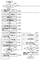
図5は図2のステップS207で行われるMF処理を説明するフローチャートである。まずステップS401ではフォーカスモードスイッチ132の状態を判定し、MFに設定されていたらステップS402へ進み、そうでなければ本MF処理を終了する。
FIG. 5 is a flowchart for explaining the MF processing performed in step S207 of FIG. First, in step S401, the state of the
ステップS402では撮像素子112の駆動モードをEVF用からMF用に切り替える。ここでMF用の駆動モードは、EVF用の駆動モードよりも毎秒あたりのコマ数が多くなるように設定されている。例えばEVF用で毎秒30コマである時、MF用では毎秒120コマになるように設定する。ステップS403では後述する手順に従って、フォーカスレンズ101の駆動判定処理を行う。ステップS404では図3で説明した手順に従って顔検出処理を行う。
In step S402, the drive mode of the
ステップS405では画像処理プロセッサ115を使って、撮像素子112から読み出した画像データにEVF128に表示するための画像処理を施す。ステップS406ではステップS405で処理した画像をEVF128に表示する。ステップS407では焦点評価値取得カウンタを所定値Nに設定し、ワークメモリ126に記憶する。ここでNは正の整数とする。ここで言う焦点評価値とは以下のようなものである。まず撮像素子112から読み出されたアナログ映像信号をA/D変換器113を使ってデジタル信号に変換する。さらに画像処理プロセッサ115において、前記デジタル信号の内の輝度信号を所定のバンドパスフィルタに通して一定の周波数帯域を抽出し、これを焦点評価値取得エリア内で積分したものである。被写体のピントが合うほど、この焦点評価値は大きくなる。ステップS408では焦点評価値の取得エリアをステップS404で検出された主顔位置に設定する。ステップS409ではフォーカスレンズ101の現在の位置を、基準位置としてワークメモリ126に記憶する。
In step S405, the
ステップS410ではフォーカスレンズ101を無限方向に所定量駆動する。このときの所定量をS1とする。ここでS1は正の整数とする。ステップS411ではフォーカスレンズ101の現在位置を取得し、ワークメモリ126に記憶する。フォーカスレンズ駆動モータ103にステッピングモータを使用する場合は、フォトインタラプタ102によって検出される初期位置からの相対駆動パルス数をもってフォーカスレンズ101の位置とする。また図示しないロータリーエンコーダ等を用いて絶対位置を測定しても良い。ステップS412では現在のフォーカスレンズ位置に対する焦点評価値を取得してワークメモリ126に記憶する。ステップS413では焦点評価値取得カウンタから1を引きワークメモリ126に記憶する。ステップS414では焦点評価値取得カウンタが0になったかどうか判定し、0であればステップS416へ、そうでなければステップS415へ進む。ステップS415ではフォーカスレンズ101を至近方向に所定量駆動する。このときの所定量をS2とする。所定量S2は、フォーカスレンズ101と絞り・シャッタ105とズームレンズ108からなる撮影光学系の結像位置が、1焦点深度分移動するのに要する駆動量であり、正の整数とする。また前述の所定量S1とは、
In step S410, the

を満たす関係となっている。
このようにステップS411からステップS415の処理を繰り返し、ステップS407で設定した所定回数N回分のフォーカスレンズ101の位置と焦点評価値をワークメモリ126に記憶する。
It is a relationship that satisfies
In this manner, the processing from step S411 to step S415 is repeated, and the position and focus evaluation value of the
ステップS416では後述する手順に従って、ピントをより鮮明に合わせるために必要なフォーカスレンズ101の駆動方向を指示するための合焦方向の判定を行う。ステップS417ではステップS416での判定の結果、ワークメモリ126に記憶された合焦方向に従って、合焦方向をEVF128に表示する。ステップS418ではステップS409で記憶した基準位置へフォーカスレンズ101を駆動する。ステップS419ではフォーカスモードスイッチ132の状態を判定し、MFに設定されていたらS403へ戻り、そうでなければステップS420へ進む。ステップS420では撮像素子112の駆動モードをMF用からEVF用に切り替える。
In step S416, the focus direction for instructing the drive direction of the
図6は図5のステップS403におけるフォーカスレンズ駆動判定を説明するフローチャートである。まずステップS501では十字SW130の右スイッチがONになっているかどうか調べ、ONであればステップS502へ、そうでなければステップS504へ進む。ステップS502ではフォーカスレンズ101を無限方向へ駆動開始する。フォーカスレンズ101は、この後駆動停止処理がなされるまで無限方向に動き続けるものとする。ステップS503ではフォーカスレンズ101が無限端に到達したかどうか調べ、到達していればステップS507へ進み、そうでなければステップS501へ戻る。なお、ここで言う無限端とは、無限遠にある被写体に合焦するフォーカスレンズ101の位置を指す。
FIG. 6 is a flowchart illustrating focus lens drive determination in step S403 in FIG. First, in step S501, it is checked whether or not the right switch of the cross switch 130 is ON. If it is ON, the process proceeds to step S502, and if not, the process proceeds to step S504. In step S502, the
ステップS504では十字SW130の左スイッチがONになっているかどうか調べ、ONであればステップS505へ、そうでなければステップS507へ進む。ステップS505ではフォーカスレンズ101を至近方向へ駆動開始する。フォーカスレンズ101は、この後駆動停止処理がなされるまで至近方向に動き続けるものとする。ステップS506ではフォーカスレンズ101が至近端に到達したかどうか調べ、到達していればステップS507へ進み、そうでなければステップS501へ戻る。なお、ここで言う至近端とは、至近距離にある被写体に合焦するフォーカスレンズ101の位置を指し、ここでは至近距離を例えば10cmとする。
In step S504, it is checked whether or not the left switch of the cross switch 130 is ON. If it is ON, the process proceeds to step S505, and if not, the process proceeds to step S507. In step S505, the
ステップS507ではフォーカスレンズ101の駆動を停止する。
In step S507, the driving of the
図7は図5のステップS416で行われる合焦方向判定処理を説明するフローチャートである。まずステップS601では図5のステップS411で記憶したN個のフォーカスレンズ101の位置においてステップS412で取得した焦点評価値の関係を調べる。そして、焦点評価値がピークを形成していればステップS602へ、形成していなければステップS603へ進む。ステップS602では図5のステップS417で表示する合焦方向を「合焦状態」としてワークメモリ126に記憶する。
FIG. 7 is a flowchart for explaining the in-focus direction determination process performed in step S416 in FIG. First, in step S601, the relationship between the focus evaluation values acquired in step S412 is examined at the positions of the N focus
また、焦点評価値が無限方向に登り止っていれば(ステップS603でYES)ステップS604へ、そうでなければステップS605へ進む。ステップS604では図5のステップS417で表示する合焦方向を「無限方向」としてワークメモリ126に記憶する。 If the focus evaluation value has stopped climbing in the infinite direction (YES in step S603), the process proceeds to step S604; otherwise, the process proceeds to step S605. In step S604, the in-focus direction displayed in step S417 of FIG.
また、焦点評価値が至近方向に登り止っていれば(ステップS605でYES)ステップS606へ、そうでなければステップS607へ進む。ステップS606では図5のステップS417で表示する合焦方向を「至近方向」としてワークメモリ126に記憶する。ステップS607では図5のステップS417で表示する合焦方向を「不明」としてワークメモリ126に記憶する。 If the focus evaluation value has stopped climbing in the closest direction (YES in step S605), the process proceeds to step S606; otherwise, the process proceeds to step S607. In step S606, the in-focus direction displayed in step S417 in FIG. In step S607, the in-focus direction displayed in step S417 in FIG.
ここで、焦点評価値と合焦方向との関係について、図8を参照して説明する。今、図5のステップS407で設定される焦点評価値取得カウンタN=3とする。すると、式(1)よりS1=S2となるので、ステップS410では、ステップS409で記憶した基準位置から所定量S2だけ無限方向にフォーカスレンズ101を駆動することになる。この位置での焦点評価値を取得した後は、ステップS415において今度はフォーカスレンズ101を至近方向に所定量S2だけ駆動する。このようにしてステップS411からステップS415を繰り返すことにより、フォーカスレンズ101の位置と焦点評価値をそれぞれ3回記憶する。このときの記憶されたフォーカスレンズ101の位置は、基準位置からS2分無限寄りの位置P1、基準位置P2、基準位置からS2分至近寄りの位置P3の3点となる。
Here, the relationship between the focus evaluation value and the in-focus direction will be described with reference to FIG. Now, it is assumed that the focus evaluation value acquisition counter N = 3 set in step S407 in FIG. Then, since S1 = S2 from the equation (1), in step S410, the
これらの位置P1〜P3における焦点評価値の関係は、図8に示すように、(a)から(d)までの4種類となる。図8において、横軸はフォーカスレンズ101の位置を示し、左側が無限方向、右側が至近方向となっている。縦軸は焦点評価値を示す。
The relationship between the focus evaluation values at these positions P1 to P3 is four types (a) to (d) as shown in FIG. In FIG. 8, the horizontal axis indicates the position of the
まず(a)では、3つの焦点評価値のうちP2の位置での焦点評価値が一番大きい。この場合は、図5のステップS409で記憶した基準位置が、最もピントが合っていると判定される。従ってこの場合の判定は合焦状態となる。 First, in (a), the focus evaluation value at the position P2 is the largest among the three focus evaluation values. In this case, it is determined that the reference position stored in step S409 in FIG. Accordingly, the determination in this case is an in-focus state.
次に(b)では、3つの焦点評価値のうちP3の位置での焦点評価値が一番大きい(至近方向に登り止り)。この場合は、P3の位置よりもさらに至近方向に合焦位置があると推測される。従ってこの場合の合焦方向の判定は至近方向となる。 Next, in (b), the focus evaluation value at the position of P3 is the largest among the three focus evaluation values (the climb stops in the closest direction). In this case, it is presumed that the in-focus position is in the closer direction than the position of P3. Therefore, the determination of the in-focus direction in this case is the close direction.
次に(c)では、3つの焦点評価値のうちP1の位置での焦点評価値が一番大きい(無限方向に登り止り)。この場合は、P1の位置よりもさらに無限方向に合焦位置があると推測される。従ってこの場合の合焦方向の判定は無限方向となる。 Next, in (c), the focus evaluation value at the position P1 is the largest among the three focus evaluation values (climbing in an infinite direction). In this case, it is estimated that the focus position is in an infinite direction further than the position of P1. Therefore, the determination of the in-focus direction in this case is an infinite direction.
次に(d)では、3つの焦点評価値のうちP2の位置での焦点評価値が一番小さい。この場合は無限方向と至近方向のどちらに合焦位置があるか分からない。従ってこの場合の合焦方向の判定は不明となる。 Next, in (d), the focus evaluation value at the position P2 is the smallest among the three focus evaluation values. In this case, it is not known whether the focusing position is in the infinite direction or the close direction. Therefore, the determination of the in-focus direction in this case is unknown.
このようにして判定された合焦方向を、図5のステップS417で説明したようにEVF128に表示する。このときの表示の仕方の一例について、図9を参照して説明する。
The in-focus direction determined in this way is displayed on the
図9には合焦表示の内容に応じて(a)から(d)まで4種類が示されている。いずれも円形のアイコンの両側に三角形のアイコンを表示している。また検出された顔位置に、合焦枠として四角形の枠が表示されている。 FIG. 9 shows four types from (a) to (d) according to the contents of the focus display. In both cases, a triangular icon is displayed on both sides of the circular icon. In addition, a square frame is displayed as a focusing frame at the detected face position.
まず(a)は合焦状態であることを示す図である。このときは中央の円形アイコンが例えば白色などで表示され、左右の三角形アイコンは例えば黒色などで表示される。また、顔位置の合焦枠は例えば緑色で表示される。 First, (a) is a diagram showing the in-focus state. At this time, the center circular icon is displayed in white, for example, and the left and right triangle icons are displayed in black, for example. The focus frame for the face position is displayed in green, for example.
次に(b)は至近方向を示す図である。このときは右側の三角形アイコンが例えば白色で表示され、中央の円形アイコンと左側の三角形アイコンは例えば黒色で表示される。また、顔位置の合焦枠は例えば黄色で表示される。 Next, (b) is a diagram showing a close direction. At this time, the right triangle icon is displayed in white, for example, and the center circular icon and the left triangle icon are displayed in black, for example. The focus frame for the face position is displayed in yellow, for example.
次に(c)は無限方向を示す図である。このときは左側の三角形アイコンが例えば白色で表示され、中央の円形アイコンと右側の三角形アイコンは例えば黒色で表示される。また、顔位置の合焦枠は例えば青色で表示される。 Next, (c) is a diagram showing an infinite direction. At this time, the left triangle icon is displayed in white, for example, and the center circular icon and the right triangle icon are displayed in black, for example. The focus frame for the face position is displayed in blue, for example.
次に(d)は不明を示す図である。このときは全てのアイコンが黒色で表示される。顔位置の合焦枠は例えば灰色で表示される。 Next, (d) is a figure which shows unknown. At this time, all icons are displayed in black. The focus frame of the face position is displayed in gray, for example.
このように、撮影者は、検出された顔の合焦状態が、撮影者が操作したフォーカスレンズ101の位置に対して至近側にあるか無限側にあるかを知ることができる。
In this way, the photographer can know whether the detected focus state of the face is on the near side or the infinite side with respect to the position of the
なお、図9に示す表示の仕方は一例であり、フォーカスレンズ101の合焦方向を撮影者に通知することができるのであれば、表示形態に特にこだわるものではない。また、表示に限らず、例えば、音声を用いても良い。
Note that the display method illustrated in FIG. 9 is an example, and the display mode is not particularly limited as long as the photographer can be notified of the in-focus direction of the
次に図5で説明したように構成した場合の、EVF128への表示用処理と焦点評価値取得のタイミングについて説明する。
Next, the display processing to the
図10は撮像素子112の駆動モードをMF用に切り替えた場合の、データ取得タイミングを表す図である。この図の中で1、2、3...の番号はコマ数を表している。
FIG. 10 is a diagram illustrating data acquisition timing when the driving mode of the
まず図5のステップS405で説明したように、1コマ目で露光された画像データ(第1の画像信号)を撮像素子112から読み出し、EVF128に表示するための画像処理を施す。このときのフォーカスレンズ101の位置は図5のステップS409で記憶する基準位置である。次に2コマ目では焦点評価値を取得する位置にフォーカスレンズ101を駆動する。そしてこのコマで露光された画像データ(第2の画像信号)を撮像素子112から読み出して焦点評価値を生成する。3コマ目と4コマ目は2コマ目と同様の処理をする。この1コマ目から4コマ目までを合計した時間は、撮像素子112の駆動モードが通常のEVF用である場合の1コマと同じ時間になっている。つまり、上述したようにEVF用で毎秒30コマ、MF用で毎秒120コマの場合、MF用の4コマでEVF用の1コマと同じ時間となるため、焦点評価値生成用に用いることのできるコマ数は3コマである。従って、焦点評価値取得カウンタNは3以下であれば良いことになる。別の例として、例えばEVF用で毎秒30コマ、MF用で毎秒150コマの場合、MF用の5コマでEVF用の1コマと同じ時間となる。この場合、焦点評価値生成用に用いることのできるコマ数は4コマであるため、焦点評価値取得カウンタNは4以下であれば良いことになる。
First, as described in step S405 in FIG. 5, image data (first image signal) exposed in the first frame is read from the
次に5コマ目では、フォーカスレンズ101を図5のステップS409で記憶した基準位置に駆動する。1コマ目と同様に、この位置で露光された画像データを撮像素子112から読み出し、EVF128に表示するための画像処理を施す。6コマ目から8コマ目は、2コマ目から4コマ目と同様の処理を行う。
Next, in the fifth frame, the
図10での各コマにおけるフォーカスレンズ101の位置は図11のようになっている。この図中で1から8の数字は図10と同様にコマ数を表している。
The position of the
まず1コマ目におけるフォーカスレンズ101の位置は、図5のステップS409で記憶する基準位置である。この位置で撮像素子112を露光し、画像データを読み出す。ここで読み出した画像データはEVF128への表示用に使用される。次に2コマ目では、フォーカスレンズ101を無限方向にS1だけ駆動する。この位置で撮像素子112を露光し、画像データを読み出す。ここで読み出した画像データは焦点評価値生成用に使用される。3コマ目では、フォーカスレンズ101を至近方向にS2だけ駆動する。この時、前述の説明のように、焦点評価値取得カウンタに設定された所定値N=3であった場合、S1=S2となる。従って3コマ目でのフォーカスレンズ101の位置は1コマ目での位置と同じになる。この位置で撮像素子112に露光し、画像データを読み出す。ここで読み出した画像データは焦点評価値生成用に使用される。4コマ目では、3コマ目と同様にフォーカスレンズ101を至近方向にS2だけ駆動する。この位置で撮像素子112に露光し、画像データを読み出す。ここで読み出した画像データは焦点評価値生成用に使用される。
First, the position of the
5コマ目では、フォーカスレンズ101を図5のステップS409で記憶した基準位置に駆動する。この位置で撮像素子112に露光し、画像データを読み出す。ここで読み出した画像データはEVF128への表示用に使用される。6コマ目から8コマ目は、2コマ目から4コマ目と同様の処理を行う。
In the fifth frame, the
このようにして、通常のEVF表示周期と同じ周期でEVF128に画像を表示しながら、合焦方向判別用に焦点評価値を取得することができる。さらにEVF128に表示する画像の毎秒当たりのコマ数が通常のEVF表示時と同じになるので、EVF128に表示する画像の更新周期が遅くならず、動きがぎこちない違和感のある表示にならない。
In this way, it is possible to acquire the focus evaluation value for determining the in-focus direction while displaying an image on the
また、EVF表示用のコマと焦点評価値取得用のコマとを区別し、焦点評価値取得用のコマの露光時のみフォーカスレンズ101を駆動する。そのため、フォーカスレンズ101が動くことによってピントが外れた画像がEVF128に表示されることがない。よってEVF128に表示される画像の焦点状態に影響を与えることがないため、見栄えが悪くならない。
Further, the EVF display frame and the focus evaluation value acquisition frame are distinguished from each other, and the
一方、MF処理を行わないときは、撮像素子112の駆動モードを通常EVF用の駆動モードにする。この駆動モードでは毎秒あたりのコマ数がMF用の駆動モードより少ないので、消費電力を抑えることができる。毎秒あたりのコマ数が少ないと撮像素子112への制御クロックの周波数を低くできるので、その分消費電力を抑えることができるからである。
On the other hand, when MF processing is not performed, the drive mode of the
<第2の実施形態>
前述した第1の実施形態では、MF処理に入った場合に撮像素子112の駆動モードをMF用の駆動モードに切り替えていた。これをEVF表示用の処理時と焦点評価値取得時とで切り替えても良い。このように構成した場合の処理について以下に説明する。
<Second Embodiment>
In the first embodiment described above, when the MF process is started, the drive mode of the
図12は第1の実施形態における図5を置き換えたものである。まずステップS1101ではフォーカスモードスイッチ132の状態を判定し、MFに設定されていたらステップS1102へ進み、そうでなければ本処理を終了する。
FIG. 12 replaces FIG. 5 in the first embodiment. First, in step S1101, the state of the
ステップS1102では撮像素子112の駆動モードをMF用からEVF用に切り替える。ステップS1103では第1の実施形態の図6で説明した手順に従って、フォーカスレンズ101の駆動判定処理を行う。ステップS1104では第1の実施形態の図3で説明した手順に従って顔検出処理を行う。ステップS1105では画像処理プロセッサ115を使って、撮像素子112から読み出した画像データにEVF128に表示するための画像処理を施す。ステップS1106ではステップS1105で処理した画像をEVF128に表示する。
In step S1102, the drive mode of the
ステップS1107では撮像素子112の駆動モードをEVF用からMF用に切り替える。ここでMF用の駆動モードは、第1の実施形態で説明したものと同様である。
In step S1107, the drive mode of the
ステップS1108からステップS1119までは、図5のステップS407からステップS418と同様の処理を行う。 From step S1108 to step S1119, processing similar to that from step S407 to step S418 in FIG. 5 is performed.
ステップS1120ではフォーカスモードスイッチ132の状態を判定し、MFに設定されていたらステップS1102へ、そうでなければステップS1121へ進む。ステップS1121では撮像素子112の駆動モードをMF用からEVF用に切り替える。
In step S1120, the state of the
上記の通り本第2の実施形態によれば、ステップS1106でEVF表示が終わってから、ステップS1107で駆動モードをEVF用からMF用に切り替えるので、図10における1コマ目と、2から4コマ目とで、1コマあたりの時間を変えることができる。従ってEVF表示用と焦点評価値生成用とで、それぞれ最適な露光時間を設定することができる。それにより様々な輝度の被写体に対して適正な露出を得ることができるので、EVF128に表示する画像の見栄えをさらに良くすることができる。
As described above, according to the second embodiment, after the EVF display is completed in step S1106, the drive mode is switched from EVF to MF in step S1107. Therefore, the first frame and the second to fourth frames in FIG. You can change the time per frame with your eyes. Accordingly, it is possible to set optimum exposure times for EVF display and focus evaluation value generation. As a result, appropriate exposure can be obtained for subjects with various luminances, so that the appearance of the image displayed on the
<第3の実施形態>
前述した第1及び第2の実施形態では、撮影者がフォーカスレンズ101を駆動し終えた後で合焦方向の判定を行うように構成したが、撮影者がフォーカスレンズ101を駆動中にも合焦方向の判定を行うようにしても良い。本第3の実施形態では、このように構成した場合の処理について以下に説明する。
<Third Embodiment>
In the above-described first and second embodiments, the focus direction is determined after the photographer finishes driving the
図13は第1の実施形態の図6のフォーカスレンズ駆動判定を置き換えたものである。まずステップS1201では十字SW130の右スイッチがONになっているかどうか調べ、ONであればステップS1202へ、そうでなければステップS1205へ進む。ステップS1202ではフォーカスレンズ101を無限方向へ駆動開始する。フォーカスレンズ101は、この後駆動停止処理がなされるまで無限方向に動き続けるものとする。ステップS1203では後述する手順に従って、合焦度変化判定を行う。ステップS1204ではフォーカスレンズ101が無限端に到達したかどうか調べ、到達していればステップS1209へ進み、そうでなければステップS1201へ戻る。
FIG. 13 replaces the focus lens drive determination of FIG. 6 of the first embodiment. First, in step S1201, it is checked whether or not the right switch of the cross switch 130 is ON. If it is ON, the process proceeds to step S1202, and if not, the process proceeds to step S1205. In step S1202, the
ステップS1205では十字SW130の左スイッチがONになっているかどうか調べ、ONであればステップS1206へ、そうでなければステップS1209へ進む。ステップS1206ではフォーカスレンズ101を至近方向へ駆動開始する。フォーカスレンズ101は、この後駆動停止処理がなされるまで至近方向に動き続けるものとする。ステップS1207では後述する手順に従って、合焦度変化判定を行う。ステップS1208ではフォーカスレンズ101が至近端に到達したかどうか調べ、到達していればステップS1209へ進み、そうでなければステップS1201へ戻る。
In step S1205, it is checked whether or not the left switch of the cross switch 130 is ON. If it is ON, the process proceeds to step S1206, and if not, the process proceeds to step S1209. In step S1206, the
ステップS1209ではフォーカスレンズ101の駆動を停止する。
In step S1209, the drive of the
図14は図13のステップS1203及びステップS1207における合焦度変化判定を説明するフローチャートである。まずステップS1301では第1の実施形態の図3で説明した手順に従って顔検出処理を行う。ステップS1302では焦点評価値の取得エリアをステップS1301で検出された主顔位置に設定する。 FIG. 14 is a flowchart for explaining the focus degree change determination in steps S1203 and S1207 in FIG. First, in step S1301, face detection processing is performed according to the procedure described in FIG. 3 of the first embodiment. In step S1302, the focus evaluation value acquisition area is set to the main face position detected in step S1301.
ステップS1303では焦点評価値取得カウンタを所定値Mに設定し、ワークメモリ126に記憶する。ここでMは正の整数とする。ここでの焦点評価値取得カウンタは、第1の実施形態の図5のステップS407で設定した焦点評価値取得カウンタとは別にワークメモリ126に記憶するものとする。
In step S1303, the focus evaluation value acquisition counter is set to a predetermined value M and stored in the
ステップS1304ではフォーカスレンズ101の現在位置を取得し、ワークメモリ126に記憶する。ステップS1305では現在のフォーカスレンズ位置に対する焦点評価値を取得してワークメモリ126に記憶する。ステップS1306ではステップS1303で設定した焦点評価値取得カウンタから1を引き、ワークメモリ126に記憶する。ステップS1307では焦点評価値取得カウンタが0になったかどうか判定し、0であればステップS1308へ進み、そうでなければステップS1304へ戻る。
In step S1304, the current position of the
ステップS1308では後述する手順に従って、合焦位置接近判定を行う。ステップS1309ではステップS1308での判定の結果、ワークメモリ126に記憶された合焦位置接近判定情報に従ってEVF128に表示する。
In step S1308, in-focus position approach determination is performed according to the procedure described later. In step S1309, as a result of the determination in step S1308, the image is displayed on the
図15は図14のステップS1308における合焦位置接近判定を説明するフローチャートである。まずステップS1401では図14のステップS1304で記憶したフォーカスレンズ101の位置においてステップS1305で取得した焦点評価値の関係を調べる。そして、焦点評価値にピークを形成していればステップS1402へ、形成していなければステップS1403へ進む。ステップS1402では図14のステップS1309で表示する合焦位置接近判定情報を「合焦状態」としてワークメモリ126に記憶する。
FIG. 15 is a flowchart for explaining the in-focus position approach determination in step S1308 of FIG. First that relationship downy the key of the focus evaluation value acquired in step S1305 at the position of the
また、焦点評価値がフォーカスレンズ101の駆動方向に登り止っていれば(ステップS1403でYES)ステップS1404へ、そうでなければステップS1405へ進む。ステップS1404では図14のステップS1309で表示する合焦位置接近判定情報を「合焦位置に近づいている」としてワークメモリ126に記憶する。
If the focus evaluation value has stopped climbing in the drive direction of the focus lens 101 (YES in step S1403), the process proceeds to step S1404; otherwise, the process proceeds to step S1405. In step S1404, the in-focus position approach determination information displayed in step S1309 in FIG. 14 is stored in the
また、焦点評価値がフォーカスレンズ101の駆動方向に下がり止っていれば(ステップS1405でYES)ステップS1406へ、そうでなければステップS1407へ進む。ステップS1406では図14のステップS1309で表示する合焦位置接近判定情報を「合焦位置から遠ざかっている」としてワークメモリ126に記憶する。ステップS1407では図14のステップS1309で表示する合焦位置接近判定情報を「不明」としてワークメモリ126に記憶する。
If the focus evaluation value has stopped decreasing in the driving direction of the focus lens 101 (YES in step S1405), the process proceeds to step S1406; otherwise, the process proceeds to step S1407. In step S1406, the in-focus position approach determination information displayed in step S1309 in FIG. 14 is stored in the
ここで、焦点評価値と合焦位置接近判定情報との関係について、図16を参照して説明する。今、図14のステップS1303での焦点評価値取得カウンタM=3とする。するとステップS1304からステップS1307までの処理の繰り返しで、焦点評価値が3つ取得される。この3つの焦点評価値を取得した際のフォーカスレンズ101の位置を、取得した順番にP4、P5、P6とする。
Here, the relationship between the focus evaluation value and the in-focus position approach determination information will be described with reference to FIG. Now, assume that the focus evaluation value acquisition counter M = 3 in step S1303 of FIG. Then, three focus evaluation values are acquired by repeating the processing from step S1304 to step S1307. The positions of the
これらの位置P4〜P6における焦点評価値の関係は、図16に示すように、(a)から(d)まで4種類となる。図16において、横軸はフォーカスレンズ101の駆動方向の位置順を示す。縦軸は焦点評価値を示す。
The relationship between the focus evaluation values at these positions P4 to P6 is four types (a) to (d) as shown in FIG. In FIG. 16, the horizontal axis indicates the position order of the driving direction of the
まず(a)では、3つの焦点評価値のうちP5の位置での焦点評価値が一番大きい。この場合は、フォーカスレンズ101がすでに合焦位置に来ていると判定される。従ってこの場合の合焦位置接近判定は合焦状態となる。
First, in (a), the focus evaluation value at the position P5 is the largest among the three focus evaluation values. In this case, it is determined that the
次に(b)では、3つの焦点評価値のうちP6の位置での焦点評価値が一番大きい。この場合は、P6の位置よりもさらにフォーカスレンズ101を駆動している方向に合焦位置があると推測される。従ってこの場合の合焦位置接近判定は合焦位置に近づいている、となる。
Next, in (b), the focus evaluation value at the position P6 is the largest among the three focus evaluation values. In this case, it is estimated that the in-focus position is in the direction in which the
次に(c)では、3つの焦点評価値のうちP4の位置での焦点評価値が一番大きい。この場合は、P4の位置よりもさらにフォーカスレンズ101を駆動している方向とは反対の方向に合焦位置があると推測される。従ってこの場合の合焦位置接近判定は合焦位置から遠ざかっている、となる。
Next, in (c), the focus evaluation value at the position P4 is the largest among the three focus evaluation values. In this case, it is estimated that the in-focus position is in a direction opposite to the direction in which the
次に(d)では、3つの焦点評価値のうちP5の位置での焦点評価値が一番小さい。この場合は無限方向と至近方向のどちらに合焦位置があるか分からない。従ってこの場合の合焦位置接近判定は不明となる。 Next, in (d), the focus evaluation value at the position P5 is the smallest among the three focus evaluation values. In this case, it is not known whether the focusing position is in the infinite direction or the close direction. Accordingly, the focus position approach determination in this case is unknown.
このようにして判定された合焦方向を、図14のステップS1309で説明したようにEVF128に表示する。このときの表示の仕方の一例について、図17を参照して説明する。
The in-focus direction thus determined is displayed on the
図17には合焦位置接近判定表示の内容に応じて(a)から(d)まで4種類の図が示されている。いずれも合焦位置接近判定の結果に応じて円形のアイコンと三角形のアイコンの両方、またはどちらか一方が表示される。また検出された顔位置に、合焦枠として四角形の枠が表示される。 FIG. 17 shows four types of diagrams from (a) to (d) according to the contents of the focus position approach determination display. In either case, a circular icon and / or a triangular icon are displayed according to the result of the in-focus position approach determination. In addition, a square frame is displayed as a focusing frame at the detected face position.
まず(a)は合焦状態であることを示す図である。このときは中央の円形アイコンが例えば白色に表示され、左右の三角形アイコンは表示されない。顔位置の合焦枠は例えば緑色で表示される。 First, (a) is a diagram showing the in-focus state. At this time, the center circular icon is displayed in white, for example, and the left and right triangle icons are not displayed. The focus frame of the face position is displayed in green, for example.
次に(b)は合焦位置に近づいている場合を示す図である。このときは左右の三角形アイコンが中央の円形アイコン側に向き、例えば白色に表示され、中央の円形アイコンは例えば黒色に表示される。顔位置の合焦枠は例えば青色で表示される。 Next, (b) is a diagram illustrating a case where the in-focus position is approaching. At this time, the left and right triangle icons are directed toward the center circular icon and displayed, for example, in white, and the center circular icon is displayed in black, for example. The focus frame of the face position is displayed in blue, for example.
次に(c)は合焦位置から遠ざかっている場合を示す図である。このときは左右の三角形アイコンが中央の円形アイコンに対して外側を向き、例えば白色に表示され、中央の円形アイコンは例えば黒色に表示される。顔位置の合焦枠は例えば黄色で表示される。 Next, (c) is a diagram showing a case where the object is away from the in-focus position. At this time, the left and right triangle icons face outward with respect to the central circular icon, for example, are displayed in white, and the central circular icon is displayed in, for example, black. The focus frame of the face position is displayed in yellow, for example.
次に(d)は不明を示す図である。このときは中央の円形アイコンが例えば黒色に表示される。左右の三角形アイコンは表示されない。顔位置の合焦枠は例えば灰色で表示される。 Next, (d) is a figure which shows unknown. At this time, the center circular icon is displayed in black, for example. The left and right triangle icons are not displayed. The focus frame of the face position is displayed in gray, for example.
このように、撮影者は、操作したフォーカスレンズ101の駆動方向に対して、検出された顔の合焦位置が、近づいているのか遠ざかっているのかを知ることができる。従って撮影者がMF操作を行いながら、合焦に近づくフォーカスレンズ101の駆動方向を知ることができる。よって仮に合焦方向とは反対方向にフォーカスレンズ101を駆動している場合でも、すぐに駆動方向を修正することができる。
Thus, the photographer can know whether the detected focus position of the face is approaching or moving away from the operated driving direction of the
<第4の実施形態>
前述したように合焦方向を判定するように構成した場合、撮影者がフォーカスレンズ101を駆動した位置と、実際の合焦位置との差異が分かる。これを利用して撮影時のフォーカスレンズ101の位置を制御することができる。この方法について以下に説明する。
<Fourth Embodiment>
When the focus direction is determined as described above, the difference between the position where the photographer drives the
図18は第1の実施形態で説明した図5のステップS407で、設定する焦点評価値取得カウンタN=5とした場合の、フォーカスレンズ101の位置と焦点評価値との関係を示す図である。このときの焦点評価値の取得位置を無限から至近方向に向かってP7からP11とする。これらの位置に対して図18のような焦点評価値が得られたとする。
FIG. 18 is a diagram illustrating the relationship between the position of the
撮影者によって駆動されたフォーカスレンズ101の位置はP9である。これに対して焦点評価値の最大値を示すフォーカスレンズ101の位置はP10である。従ってP10が合焦位置であると推測される。したがって、このP9とP10にあたる位置にフォーカスレンズ101を駆動して撮影を行う。この際の撮影手順を以下で説明する。
The position of the
図19は第1の実施形態における図4の撮影処理をMF時撮影処理として置き換えたものである。まずステップS1901では両位置撮影モードに設定されているかどうか判定し、設定されていればステップS1902へ、そうでなければステップS1906へ進む。この両位置撮影モードとは、撮影者の操作によって駆動されたフォーカスレンズ101の位置と、図18を使って説明した実際の合焦位置との両方の位置で撮影を行うモードである。これはモードスイッチ124に両位置撮影モードを割り当て、これを操作することにより設定することができる。ステップS1902では撮影者の操作によって駆動された位置へフォーカスレンズ101を駆動する。これは図18のP9にあたる。ステップS1903では図4で説明した撮影処理を行う。ステップS1904では実際の合焦位置へフォーカスレンズ101を駆動する。これは図18のP10にあたる。ステップS1905では図4で説明した撮影処理を行う。
FIG. 19 is obtained by replacing the shooting process of FIG. 4 in the first embodiment with a shooting process during MF. First, in step S1901, it is determined whether or not the dual-position shooting mode is set. If it is set, the process proceeds to step S1902, and if not, the process proceeds to step S1906. The both-position shooting mode is a mode in which shooting is performed at both the position of the
ステップS1906では撮影の際のフォーカスレンズ101の位置として、実際の合焦位置が選択されているかどうか判定し、選択されていればステップS1907へ、そうでなければステップS1909へ進む。これは設定スイッチ129を操作することによって設定される。ステップS1907では実際の合焦位置へフォーカスレンズ101を駆動する。これは図18のP10にあたる。ステップS1908では図4で説明した撮影処理を行う。ステップS1909では撮影者の操作によって駆動された位置へフォーカスレンズ101を駆動する。これは図18のP9にあたる。ステップS1910では図4で説明した撮影処理を行う。
In step S1906, it is determined whether or not the actual focus position is selected as the position of the
このようにして撮影時のフォーカスレンズ101の位置を、撮影者が駆動した位置と実際の合焦位置との両方にするか、またはどちらか一方にするか選ぶ事ができる。従ってフォーカスレンズ101の位置として、撮影者自身の操作による、撮影者の意図を反映した位置と、カメラが検出した焦点評価値に基づく位置の両方またはどちらか一方を選ぶことができる。これにより撮影時の選択肢が増え、多彩な表現による撮影を行うことができる。
In this way, the position of the
101 フォーカスレンズ
103 フォーカスレンズ駆動モータ
104 フォーカスレンズ駆動回路
112 撮像素子
119 CPU
130 十字スイッチ
132 フォーカスモードスイッチ
DESCRIPTION OF
130
Claims (7)
前記撮像手段による撮影を制御する撮像制御手段と、
前記画像信号を表示する表示手段と、
前記画像信号から、画像の焦点状態を示す焦点評価値を求める取得手段と、
前記画像信号の内、予め設定された数のコマおきに得られる第1の画像信号を前記表示手段により表示し、前記第1の画像信号のコマを除くコマで得られる第2の画像信号を前記取得手段による焦点評価値の取得に用いるように制御する制御手段と、
前記取得手段により求められた焦点評価値に基づいて、合焦状態とするための前記フォーカスレンズの駆動方向を判定し、該判定された駆動方向を前記表示手段に表示させる判定手段と、
前記フォーカスレンズをマニュアルで駆動する指示を入力する操作手段と、を有し、
前記判定手段は、前記取得手段により求められた焦点評価値に基づいて、前記フォーカスレンズの合焦位置を判定し、
前記撮像制御手段は、前記第2の画像信号のコマでの撮影のために、コマごとに異なるフォーカスレンズ位置に前記フォーカスレンズを駆動して前記被写体の撮影を行い、前記被写体の本撮影として、1回の撮影指示によって前記フォーカスレンズの位置が前記判定手段により判定された合焦位置で撮影された画像と、前記フォーカスレンズの位置が前記操作手段による指示に基づいて駆動された位置で撮影された画像との両方を撮影することを特徴とする撮像装置。 An image pickup unit that has an image pickup device that picks up an optical image of a subject incident through a focus lens and converts the image into an electric signal, and sequentially outputs the converted electric signal as an image signal;
Imaging control means for controlling imaging by the imaging means;
Display means for displaying the image signal;
Obtaining means for obtaining a focus evaluation value indicating a focus state of an image from the image signal;
Of the image signals, a first image signal obtained every preset number of frames is displayed by the display means, and a second image signal obtained by frames other than the frames of the first image signal is displayed. Control means for controlling to use for obtaining the focus evaluation value by the obtaining means;
A determination unit that determines a drive direction of the focus lens for achieving a focused state based on the focus evaluation value obtained by the acquisition unit, and causes the display unit to display the determined drive direction;
Operation means for inputting an instruction to manually drive the focus lens,
The determination unit determines a focus position of the focus lens based on the focus evaluation value obtained by the acquisition unit,
The imaging control unit performs imaging of the subject by driving the focus lens to a different focus lens position for each frame for imaging with the frame of the second image signal. An image taken at the in-focus position where the position of the focus lens is determined by the determination unit by one shooting instruction, and a position where the position of the focus lens is driven based on an instruction from the operation unit An image pickup apparatus that takes both images.
前記撮像装置は、前記各コマの画像信号から得られた前記焦点評価値に基づいて、前記フォーカスレンズの駆動方向が合焦状態に接近する方向であるかどうかを判定し、該判定の結果を前記表示手段に表示させる手段を更に有することを特徴とする請求項5に記載の撮像装置。 The control means further controls to obtain a focus evaluation value by the acquisition means from an image signal of each frame obtained from the imaging means during driving of the focus lens based on an instruction from the operation means,
The imaging device determines whether the driving direction of the focus lens is a direction approaching a focused state based on the focus evaluation value obtained from the image signal of each frame, and the result of the determination 6. The imaging apparatus according to claim 5, further comprising means for displaying on the display means.
制御手段により、前記画像信号の内、予め設定された数のコマおきに得られる第1の画像信号を前記表示手段に表示する表示工程と、
取得手段が、前記画像信号の内、前記第1の画像信号のコマを除くコマで得られる第2の画像信号から、画像の焦点状態を示す焦点評価値を求める取得工程と、
判定手段が、前記取得工程で求められた焦点評価値に基づいて、合焦状態とするための前記フォーカスレンズの駆動方向を判定し、該判定された駆動方向を前記表示手段に表示させる判定工程と、
前記フォーカスレンズをマニュアルで駆動する指示を入力する操作工程と、を有し、
前記判定工程では、前記取得工程で求められた焦点評価値に基づいて、前記フォーカスレンズの合焦位置を判定し、
前記撮像手段が、前記取得工程において、前記第2の画像信号のコマでの撮影のために、コマごとに異なるフォーカスレンズ位置に前記フォーカスレンズを移動して前記被写体の撮影を行い、被写体の本撮影として、1回の撮影指示によって前記フォーカスレンズの位置が前記判定工程において判定された合焦位置で撮影された画像と、前記フォーカスレンズの位置が前記操作工程における指示に基づいて駆動された位置で撮影された画像との両方を撮影することを特徴とする撮像装置の制御方法。 An imaging unit that captures an optical image of a subject incident through the focus lens, converts the optical image into an electrical signal by an imaging device, and sequentially outputs the converted electrical signal as an image signal; and a display unit that displays the image signal A method for controlling an imaging apparatus having:
A display step of displaying, on the display means, a first image signal obtained every predetermined number of frames of the image signal by the control means;
An obtaining step for obtaining a focus evaluation value indicating a focus state of an image from a second image signal obtained by a frame excluding the frame of the first image signal in the image signal;
A determining step that determines a driving direction of the focus lens for achieving the in-focus state based on the focus evaluation value obtained in the obtaining step, and causes the display unit to display the determined driving direction. When,
An operation step of inputting an instruction to manually drive the focus lens,
In the determination step, the focus position of the focus lens is determined based on the focus evaluation value obtained in the acquisition step,
In the acquisition step, the imaging means moves the focus lens to a different focus lens position for each frame and shoots the subject in order to capture the second image signal with the frame, As shooting, an image shot at the in-focus position where the position of the focus lens is determined in the determination step by a single shooting instruction, and a position where the position of the focus lens is driven based on the instruction in the operation step A method for controlling an image pickup apparatus, characterized in that both an image taken with a camera and an image taken with a camera are photographed.
Priority Applications (2)
| Application Number | Priority Date | Filing Date | Title |
|---|---|---|---|
| JP2009001825A JP5411508B2 (en) | 2009-01-07 | 2009-01-07 | Imaging apparatus and control method thereof |
| US12/651,904 US8300137B2 (en) | 2009-01-07 | 2010-01-04 | Image sensing apparatus providing driving direction of focus lens for attaining in-focus state and control method therefor |
Applications Claiming Priority (1)
| Application Number | Priority Date | Filing Date | Title |
|---|---|---|---|
| JP2009001825A JP5411508B2 (en) | 2009-01-07 | 2009-01-07 | Imaging apparatus and control method thereof |
Publications (3)
| Publication Number | Publication Date |
|---|---|
| JP2010160269A JP2010160269A (en) | 2010-07-22 |
| JP2010160269A5 JP2010160269A5 (en) | 2011-12-01 |
| JP5411508B2 true JP5411508B2 (en) | 2014-02-12 |
Family
ID=42311447
Family Applications (1)
| Application Number | Title | Priority Date | Filing Date |
|---|---|---|---|
| JP2009001825A Expired - Fee Related JP5411508B2 (en) | 2009-01-07 | 2009-01-07 | Imaging apparatus and control method thereof |
Country Status (2)
| Country | Link |
|---|---|
| US (1) | US8300137B2 (en) |
| JP (1) | JP5411508B2 (en) |
Families Citing this family (15)
| Publication number | Priority date | Publication date | Assignee | Title |
|---|---|---|---|---|
| US8600226B2 (en) * | 2010-08-30 | 2013-12-03 | Samsung Electronics Co., Ltd. | Focusing methods and apparatus, and recording media for recording the methods |
| US8525923B2 (en) * | 2010-08-30 | 2013-09-03 | Samsung Electronics Co., Ltd. | Focusing method and apparatus, and recording medium for recording the method |
| KR101720776B1 (en) | 2010-12-27 | 2017-03-28 | 삼성전자주식회사 | Digital image photographing apparatus and method for controlling the same |
| TWI440951B (en) * | 2011-11-09 | 2014-06-11 | Altek Corp | Lens actuating device and lens actuating method thereof |
| CN103124329B (en) * | 2011-11-18 | 2018-08-14 | 三星电子株式会社 | Image pick up equipment, drive control method |
| US9122129B2 (en) | 2011-11-18 | 2015-09-01 | Samsung Electronics Co., Ltd. | Image pickup apparatus, driving control method thereof, and computer-readable recording medium |
| JP6172901B2 (en) * | 2012-08-06 | 2017-08-02 | オリンパス株式会社 | Imaging device |
| KR20140091959A (en) * | 2013-01-14 | 2014-07-23 | 삼성전자주식회사 | A focus Aid System |
| US9124823B2 (en) * | 2013-05-20 | 2015-09-01 | Omnivision Technologies, Inc. | Image sensor with fast intra-frame focus |
| US9462179B2 (en) | 2013-05-20 | 2016-10-04 | Omnivision Technologies, Inc. | Image sensor with fast intra-frame focus |
| JP6102558B2 (en) * | 2013-06-20 | 2017-03-29 | ソニー株式会社 | Imaging apparatus, information display method, and information processing apparatus |
| JP6296887B2 (en) * | 2014-05-07 | 2018-03-20 | キヤノン株式会社 | Focus adjustment apparatus and control method thereof |
| US20160295122A1 (en) * | 2015-04-03 | 2016-10-06 | Canon Kabushiki Kaisha | Display control apparatus, display control method, and image capturing apparatus |
| JP6548436B2 (en) * | 2015-04-03 | 2019-07-24 | キヤノン株式会社 | Focus detection apparatus and control method thereof |
| CN106060373B (en) | 2015-04-03 | 2019-12-20 | 佳能株式会社 | Focus detection apparatus and control method thereof |
Family Cites Families (15)
| Publication number | Priority date | Publication date | Assignee | Title |
|---|---|---|---|---|
| KR0157459B1 (en) | 1993-02-04 | 1998-11-16 | 김광호 | Apparatus for lens focus control |
| US6377305B2 (en) * | 1997-10-13 | 2002-04-23 | Canon Kabushiki Kaisha | Image sensing apparatus |
| JP4355847B2 (en) * | 2000-09-04 | 2009-11-04 | 富士フイルム株式会社 | Camera focus information display apparatus and method |
| JP3728241B2 (en) * | 2001-12-20 | 2005-12-21 | キヤノン株式会社 | Focus adjustment apparatus, imaging apparatus, focusing method, program, and storage medium |
| JP3956284B2 (en) * | 2002-03-12 | 2007-08-08 | コニカミノルタフォトイメージング株式会社 | Imaging device |
| JP2004023747A (en) * | 2002-06-20 | 2004-01-22 | Minolta Co Ltd | Electronic camera |
| US20040036792A1 (en) * | 2002-08-23 | 2004-02-26 | Chikatsu Moriya | Camera system and focus information display apparatus |
| JP2004254256A (en) * | 2003-02-24 | 2004-09-09 | Casio Comput Co Ltd | Camera apparatus, display method, and program |
| JP2005084632A (en) * | 2003-09-11 | 2005-03-31 | Toshiba Corp | Electronic camera and electronic camera control method |
| JP2005140943A (en) * | 2003-11-06 | 2005-06-02 | Canon Inc | Focusing-assisting device, drive unit, photographic lens, and photographic system |
| JP2005037963A (en) * | 2004-09-13 | 2005-02-10 | Konica Minolta Photo Imaging Inc | Digital camera |
| JP5247003B2 (en) * | 2006-02-20 | 2013-07-24 | キヤノン株式会社 | Imaging device |
| JP2008216503A (en) * | 2007-03-01 | 2008-09-18 | Canon Inc | Imaging apparatus |
| JP2009103912A (en) * | 2007-10-23 | 2009-05-14 | Olympus Corp | Image pickup apparatus |
| JP2009229927A (en) * | 2008-03-24 | 2009-10-08 | Olympus Corp | Autofocus adjustment device and imaging apparatus |
-
2009
- 2009-01-07 JP JP2009001825A patent/JP5411508B2/en not_active Expired - Fee Related
-
2010
- 2010-01-04 US US12/651,904 patent/US8300137B2/en not_active Expired - Fee Related
Also Published As
| Publication number | Publication date |
|---|---|
| US8300137B2 (en) | 2012-10-30 |
| JP2010160269A (en) | 2010-07-22 |
| US20100171871A1 (en) | 2010-07-08 |
Similar Documents
| Publication | Publication Date | Title |
|---|---|---|
| JP5411508B2 (en) | Imaging apparatus and control method thereof | |
| JP6512810B2 (en) | Image pickup apparatus, control method and program | |
| JP5159515B2 (en) | Image processing apparatus and control method thereof | |
| JP4582212B2 (en) | Imaging apparatus and program | |
| JP4843002B2 (en) | IMAGING DEVICE, IMAGING DEVICE CONTROL METHOD, AND COMPUTER PROGRAM | |
| US8786749B2 (en) | Digital photographing apparatus for displaying an icon corresponding to a subject feature and method of controlling the same | |
| JP2010093422A (en) | Imaging apparatus | |
| JP4730478B2 (en) | IMAGING DEVICE, IMAGING DEVICE CONTROL METHOD, AND PROGRAM | |
| KR20070088586A (en) | Image processing apparatus and image processing method | |
| US8648960B2 (en) | Digital photographing apparatus and control method thereof | |
| JP2009089174A (en) | Digital camera and photographing method thereof | |
| EP2461570A1 (en) | Control device, image-capturing system, control method, and program | |
| JP2010226694A (en) | Image processor and method of image processing | |
| JP2008118387A (en) | Imaging device | |
| JP2008176152A (en) | Imaging apparatus | |
| CN111107276A (en) | Information processing apparatus, control method thereof, storage medium, and imaging system | |
| KR101567814B1 (en) | A method a device and a computer-readable storage medium of providing slide show | |
| EP2597612A1 (en) | Digital photographing apparatus and control method thereof | |
| JP6431429B2 (en) | IMAGING DEVICE, ITS CONTROL METHOD, PROGRAM, AND STORAGE MEDIUM | |
| JP5125774B2 (en) | camera | |
| JP2008139658A (en) | Focusing device, imaging apparatus, and control method thereof | |
| KR20130052372A (en) | Digital photographing apparatus and method thereof | |
| JP5911300B2 (en) | Imaging apparatus and control method thereof | |
| KR101635102B1 (en) | Digital photographing apparatus and controlling method thereof | |
| JP2008098739A (en) | Imaging apparatus, image processing method used for imaging apparatus and program making computer execute same image processing method |
Legal Events
| Date | Code | Title | Description |
|---|---|---|---|
| A521 | Request for written amendment filed |
Free format text: JAPANESE INTERMEDIATE CODE: A523 Effective date: 20111012 |
|
| A621 | Written request for application examination |
Free format text: JAPANESE INTERMEDIATE CODE: A621 Effective date: 20111012 |
|
| A977 | Report on retrieval |
Free format text: JAPANESE INTERMEDIATE CODE: A971007 Effective date: 20120518 |
|
| A131 | Notification of reasons for refusal |
Free format text: JAPANESE INTERMEDIATE CODE: A131 Effective date: 20120604 |
|
| A521 | Request for written amendment filed |
Free format text: JAPANESE INTERMEDIATE CODE: A523 Effective date: 20120803 |
|
| A131 | Notification of reasons for refusal |
Free format text: JAPANESE INTERMEDIATE CODE: A131 Effective date: 20130204 |
|
| A521 | Request for written amendment filed |
Free format text: JAPANESE INTERMEDIATE CODE: A523 Effective date: 20130404 |
|
| TRDD | Decision of grant or rejection written | ||
| A01 | Written decision to grant a patent or to grant a registration (utility model) |
Free format text: JAPANESE INTERMEDIATE CODE: A01 Effective date: 20131011 |
|
| A61 | First payment of annual fees (during grant procedure) |
Free format text: JAPANESE INTERMEDIATE CODE: A61 Effective date: 20131108 |
|
| R151 | Written notification of patent or utility model registration |
Ref document number: 5411508 Country of ref document: JP Free format text: JAPANESE INTERMEDIATE CODE: R151 |
|
| LAPS | Cancellation because of no payment of annual fees |