JP5410675B2 - Water treatment system - Google Patents
Water treatment system Download PDFInfo
- Publication number
- JP5410675B2 JP5410675B2 JP2007516080A JP2007516080A JP5410675B2 JP 5410675 B2 JP5410675 B2 JP 5410675B2 JP 2007516080 A JP2007516080 A JP 2007516080A JP 2007516080 A JP2007516080 A JP 2007516080A JP 5410675 B2 JP5410675 B2 JP 5410675B2
- Authority
- JP
- Japan
- Prior art keywords
- water treatment
- treatment system
- battery
- lamp
- controller
- Prior art date
- Legal status (The legal status is an assumption and is not a legal conclusion. Google has not performed a legal analysis and makes no representation as to the accuracy of the status listed.)
- Expired - Fee Related
Links
- XLYOFNOQVPJJNP-UHFFFAOYSA-N water Substances O XLYOFNOQVPJJNP-UHFFFAOYSA-N 0.000 title claims abstract description 132
- 230000005611 electricity Effects 0.000 claims description 23
- 230000005540 biological transmission Effects 0.000 claims description 10
- 238000012545 processing Methods 0.000 claims description 3
- 238000012544 monitoring process Methods 0.000 claims 8
- 230000001678 irradiating effect Effects 0.000 claims 1
- 239000000356 contaminant Substances 0.000 description 5
- 238000000034 method Methods 0.000 description 5
- 238000013461 design Methods 0.000 description 3
- 230000006870 function Effects 0.000 description 3
- 230000003287 optical effect Effects 0.000 description 3
- OKTJSMMVPCPJKN-UHFFFAOYSA-N Carbon Chemical compound [C] OKTJSMMVPCPJKN-UHFFFAOYSA-N 0.000 description 2
- 239000003990 capacitor Substances 0.000 description 2
- 229910052799 carbon Inorganic materials 0.000 description 2
- 238000010586 diagram Methods 0.000 description 2
- 244000052769 pathogen Species 0.000 description 2
- 239000000126 substance Substances 0.000 description 2
- 238000009281 ultraviolet germicidal irradiation Methods 0.000 description 2
- 241000894006 Bacteria Species 0.000 description 1
- WHXSMMKQMYFTQS-UHFFFAOYSA-N Lithium Chemical compound [Li] WHXSMMKQMYFTQS-UHFFFAOYSA-N 0.000 description 1
- 239000004809 Teflon Substances 0.000 description 1
- 229920006362 Teflon® Polymers 0.000 description 1
- 230000004913 activation Effects 0.000 description 1
- 239000003344 environmental pollutant Substances 0.000 description 1
- 239000011521 glass Substances 0.000 description 1
- 239000004973 liquid crystal related substance Substances 0.000 description 1
- 229910052744 lithium Inorganic materials 0.000 description 1
- 239000000463 material Substances 0.000 description 1
- 244000005700 microbiome Species 0.000 description 1
- 238000012986 modification Methods 0.000 description 1
- 230000004048 modification Effects 0.000 description 1
- 239000004033 plastic Substances 0.000 description 1
- 231100000719 pollutant Toxicity 0.000 description 1
- -1 polytetrafluoroethylene Polymers 0.000 description 1
- 229920001343 polytetrafluoroethylene Polymers 0.000 description 1
- 239000004810 polytetrafluoroethylene Substances 0.000 description 1
- 238000000746 purification Methods 0.000 description 1
- 239000010453 quartz Substances 0.000 description 1
- 230000005855 radiation Effects 0.000 description 1
- VYPSYNLAJGMNEJ-UHFFFAOYSA-N silicon dioxide Inorganic materials O=[Si]=O VYPSYNLAJGMNEJ-UHFFFAOYSA-N 0.000 description 1
Images


Classifications
-
- C—CHEMISTRY; METALLURGY
- C02—TREATMENT OF WATER, WASTE WATER, SEWAGE, OR SLUDGE
- C02F—TREATMENT OF WATER, WASTE WATER, SEWAGE, OR SLUDGE
- C02F1/00—Treatment of water, waste water, or sewage
- C02F1/30—Treatment of water, waste water, or sewage by irradiation
- C02F1/32—Treatment of water, waste water, or sewage by irradiation with ultraviolet light
- C02F1/325—Irradiation devices or lamp constructions
-
- B—PERFORMING OPERATIONS; TRANSPORTING
- B01—PHYSICAL OR CHEMICAL PROCESSES OR APPARATUS IN GENERAL
- B01D—SEPARATION
- B01D35/00—Filtering devices having features not specifically covered by groups B01D24/00 - B01D33/00, or for applications not specifically covered by groups B01D24/00 - B01D33/00; Auxiliary devices for filtration; Filter housing constructions
-
- B—PERFORMING OPERATIONS; TRANSPORTING
- B01—PHYSICAL OR CHEMICAL PROCESSES OR APPARATUS IN GENERAL
- B01J—CHEMICAL OR PHYSICAL PROCESSES, e.g. CATALYSIS OR COLLOID CHEMISTRY; THEIR RELEVANT APPARATUS
- B01J19/00—Chemical, physical or physico-chemical processes in general; Their relevant apparatus
- B01J19/08—Processes employing the direct application of electric or wave energy, or particle radiation; Apparatus therefor
- B01J19/12—Processes employing the direct application of electric or wave energy, or particle radiation; Apparatus therefor employing electromagnetic waves
- B01J19/122—Incoherent waves
- B01J19/123—Ultra-violet light
-
- B—PERFORMING OPERATIONS; TRANSPORTING
- B01—PHYSICAL OR CHEMICAL PROCESSES OR APPARATUS IN GENERAL
- B01J—CHEMICAL OR PHYSICAL PROCESSES, e.g. CATALYSIS OR COLLOID CHEMISTRY; THEIR RELEVANT APPARATUS
- B01J2219/00—Chemical, physical or physico-chemical processes in general; Their relevant apparatus
- B01J2219/08—Processes employing the direct application of electric or wave energy, or particle radiation; Apparatus therefor
- B01J2219/0873—Materials to be treated
- B01J2219/0877—Liquid
-
- C—CHEMISTRY; METALLURGY
- C02—TREATMENT OF WATER, WASTE WATER, SEWAGE, OR SLUDGE
- C02F—TREATMENT OF WATER, WASTE WATER, SEWAGE, OR SLUDGE
- C02F1/00—Treatment of water, waste water, or sewage
- C02F1/001—Processes for the treatment of water whereby the filtration technique is of importance
-
- C—CHEMISTRY; METALLURGY
- C02—TREATMENT OF WATER, WASTE WATER, SEWAGE, OR SLUDGE
- C02F—TREATMENT OF WATER, WASTE WATER, SEWAGE, OR SLUDGE
- C02F1/00—Treatment of water, waste water, or sewage
- C02F1/28—Treatment of water, waste water, or sewage by sorption
- C02F1/283—Treatment of water, waste water, or sewage by sorption using coal, charred products, or inorganic mixtures containing them
-
- C—CHEMISTRY; METALLURGY
- C02—TREATMENT OF WATER, WASTE WATER, SEWAGE, OR SLUDGE
- C02F—TREATMENT OF WATER, WASTE WATER, SEWAGE, OR SLUDGE
- C02F2201/00—Apparatus for treatment of water, waste water or sewage
- C02F2201/008—Mobile apparatus and plants, e.g. mounted on a vehicle
-
- C—CHEMISTRY; METALLURGY
- C02—TREATMENT OF WATER, WASTE WATER, SEWAGE, OR SLUDGE
- C02F—TREATMENT OF WATER, WASTE WATER, SEWAGE, OR SLUDGE
- C02F2201/00—Apparatus for treatment of water, waste water or sewage
- C02F2201/009—Apparatus with independent power supply, e.g. solar cells, windpower, fuel cells
-
- C—CHEMISTRY; METALLURGY
- C02—TREATMENT OF WATER, WASTE WATER, SEWAGE, OR SLUDGE
- C02F—TREATMENT OF WATER, WASTE WATER, SEWAGE, OR SLUDGE
- C02F2201/00—Apparatus for treatment of water, waste water or sewage
- C02F2201/32—Details relating to UV-irradiation devices
- C02F2201/326—Lamp control systems
-
- Y—GENERAL TAGGING OF NEW TECHNOLOGICAL DEVELOPMENTS; GENERAL TAGGING OF CROSS-SECTIONAL TECHNOLOGIES SPANNING OVER SEVERAL SECTIONS OF THE IPC; TECHNICAL SUBJECTS COVERED BY FORMER USPC CROSS-REFERENCE ART COLLECTIONS [XRACs] AND DIGESTS
- Y02—TECHNOLOGIES OR APPLICATIONS FOR MITIGATION OR ADAPTATION AGAINST CLIMATE CHANGE
- Y02A—TECHNOLOGIES FOR ADAPTATION TO CLIMATE CHANGE
- Y02A20/00—Water conservation; Efficient water supply; Efficient water use
- Y02A20/20—Controlling water pollution; Waste water treatment
- Y02A20/208—Off-grid powered water treatment
- Y02A20/212—Solar-powered wastewater sewage treatment, e.g. spray evaporation
-
- Y—GENERAL TAGGING OF NEW TECHNOLOGICAL DEVELOPMENTS; GENERAL TAGGING OF CROSS-SECTIONAL TECHNOLOGIES SPANNING OVER SEVERAL SECTIONS OF THE IPC; TECHNICAL SUBJECTS COVERED BY FORMER USPC CROSS-REFERENCE ART COLLECTIONS [XRACs] AND DIGESTS
- Y02—TECHNOLOGIES OR APPLICATIONS FOR MITIGATION OR ADAPTATION AGAINST CLIMATE CHANGE
- Y02W—CLIMATE CHANGE MITIGATION TECHNOLOGIES RELATED TO WASTEWATER TREATMENT OR WASTE MANAGEMENT
- Y02W10/00—Technologies for wastewater treatment
- Y02W10/30—Wastewater or sewage treatment systems using renewable energies
- Y02W10/37—Wastewater or sewage treatment systems using renewable energies using solar energy
Abstract
Description
本発明は、水処理システムに関し、特に、ポータブル水処理システムに関する。 The present invention relates to a water treatment system, and more particularly to a portable water treatment system.
水処理システムは、病原体、化学汚染物質、濁度を自ら取り除くものである。ある水処理システムでは、汚染物質を取り除くためにフィルタが使用され、水に放射線を照射するために紫外線(UV)ランプが使用される。ポンプは、そのシステムに水を通すために使用される。 The water treatment system removes pathogens, chemical pollutants and turbidity by itself. In some water treatment systems, filters are used to remove contaminants, and ultraviolet (UV) lamps are used to irradiate the water with radiation. The pump is used to pass water through the system.
ランプを用いた上記の様な水処理システムの操作は、電気が必要となる。しかし、水処理システムは、電気が提供されない場所で、よく必要とされる。電気が利用できない場所での仕様のための、水処理システムを開発する必要がある。 The operation of the water treatment system as described above using a lamp requires electricity. However, water treatment systems are often needed where no electricity is provided. There is a need to develop water treatment systems for specifications where electricity is not available.
そのような水処理システムの1つは、パパンドリアによって権利付与された米国特許番号4,849,100の「ポータブル水処理システム」に示される。その水処理システムは、微粒子フィルタ、UVリアクター、脱石灰ユニットを含む。そのシステムは、AC出力及び12VDC電源のどちらかの電気を受電する。そのシステムは、相対的に小さいが、そのシステムは、組み立て前の状態で輸送され、使用時に組み立てられる。さらに、そのシステムは、別個の電源が必要となる。 One such water treatment system is shown in “Portable Water Treatment System” in US Pat. No. 4,849,100, granted by Papandaria. The water treatment system includes a particulate filter, a UV reactor, and a decalcification unit. The system receives either AC output or 12 VDC power. Although the system is relatively small, the system is shipped in a pre-assembled state and assembled at the time of use. In addition, the system requires a separate power source.
別の水処理システムが、メイデン等によって権利付与された米国特許番号5,900,212の「ハンドヘルド紫外光水浄化システム」に示される。メイデン・システムは、水処理用のUVランプを有する水処理システムを対象とする。そのシステムは、電源として機能する3.4ボルトのリチウム・バッテリを含む。メイデンシステムは、淀んだ水に対して、例えば、水筒やバケツの状態で沈められるランプを提供する。 Another water treatment system is shown in US Pat. No. 5,900,212 “Handheld Ultraviolet Light Water Purification System” granted by Maiden et al. The Maiden system is intended for water treatment systems that have UV lamps for water treatment. The system includes a 3.4 volt lithium battery that functions as a power source. The Maiden system provides lamps that can be submerged in stagnant water, for example in a water bottle or bucket.
通常のポータブル水処理システムは、無用の化学物資、病原体、又は他の汚染物質を、水から除去することが可能であるが、それらは、欠点がある。第1に、通常の水処理システムは、UVランプに電気を供給する電源に接続されなければならない。そのシステムが電池を有する場合、その電池は、再充電又は新電池が獲得されるまで、使用できない。第2に、装置が、相対的に大きいことである。これらのシステムは、たいてい非常に大きく、通常のバックパック又はハンドバックに入れることはできない。ユーザが、そのシステムを、かなり遠い距離に運ばなければならない場合、これは重大な問題になり得る。最後に、水処理システムは、電池に接続される場合、電池は、その水が十分に照射されるように、UVランプに、電源を供給できないかもしれない。 Although conventional portable water treatment systems can remove unwanted chemicals, pathogens, or other contaminants from water, they have drawbacks. First, a typical water treatment system must be connected to a power source that supplies electricity to the UV lamp. If the system has a battery, the battery cannot be used until recharging or a new battery is acquired. Second, the device is relatively large. These systems are usually very large and cannot be placed in a regular backpack or handbag. This can be a serious problem if the user has to carry the system far away. Finally, if the water treatment system is connected to a battery, the battery may not be able to supply power to the UV lamp so that its water is well illuminated.
それゆえ、これらの欠点を克服する改良された水処理システムが、高く望まれる。 Therefore, an improved water treatment system that overcomes these drawbacks is highly desirable.
図1は、水処理システム5の機能ブロック図である。フィルタ10、UV透過リアクタ14、及びUVランプ16は、水処理システム5のための処理サブシステムを形成する。まず最初に、水は、そのシステムに入り、フイルタ10を通過する。フィルタ10は、カーボンフィルタのように、水から汚染物質を取り除くことができる。ポンプ12は、直流(DC)ポンプが望ましい。ポンプ12は、ハウジング又は入口アセンブリ内に含められる。水は、ポンプ12を出た後、UV透過リアクタ14を通過する。UVランプ16からの光は、UV透過リアクタ14の中の水を浄化する。その後、水は、水処理システムを出る。
FIG. 1 is a functional block diagram of the water treatment system 5. The
コントローラ18は、水処理システム5の運転を管理する。コントローラ18は、マイクロコントローラ、又は、マイクロプロセッサでも良い。コントローラ18が、マイクロコントローラの場合、外部メモリ及び他の必要な回路が提供される。
The
コントローラ18は、水が、UV透過リアクタ14の中で十分な照射時間滞留するように、ポンプ14を制御する。ランプセンサ20は、コントローラ18に、UVランプ16の運転特性に関する情報を提供する。UVランプ16が十分な強度で作動しないことを、ランプセンサ20が検出する場合、コントローラ18が、さらに水を処理しようとしないように、ポンプ12を止める。ある応用例では、水処理システム5は、ユーザに濾過された水を提供しながら、UVランプ16を機能させずに、操作的に運転することができる。
The
再充電可能な蓄電デバイス22は、水処理システム5に電気を供給する。蓄電デバイス22は、乾電池、湿電池、コンデンサ、スーパーコンデンサ、他の蓄電装置を有する。充電制御回路24は、電源26はもちろんのこと蓄電デバイス22も監視する。充電制御回路24は、蓄電デバイス22の状況及びタイプに関する情報を、コントローラ18に提供する。
The rechargeable
充電制御回路24は、電源26の状況も監視する。電源26は、ダイナモ、スプリング・ジェネレータ、太陽電池、DC電源、又は、AC電源を有する手回しクランク発電機とすることができる。過剰な電力が、電源26から利用可能な場合、充電制御回路24は、蓄電デバイス22がさらに充電できるかどうか判断する。もし可能なら、充電制御回路24は、蓄電デバイス22の充電を可能にする。
The
この機能を実行するために、内部メモリ、又は、コントローラ18に接続されたメモリは、UVランプ16及びポンプ12を運転するための電源要求を有する。電源26によって提供される電力を比較することによって、コントローラ18は、十分な電力が、UVランプ16及びポンプ12を操作するためにあるかどうか判断し、そして同時に、蓄電デバイス22を再充電する。
In order to perform this function, the internal memory or memory connected to the
コントローラ18は、フラッシュライト制御回路28にも接続される。フラッシュライト制御回路28は、フラッシュライト30に接続される。コントローラ18は、例えば、(後述される)フラッシュライト30に電圧をかけるためのスイッチ32の1つから、ある信号を受信する場合、コントローラ18は、十分な電気が、蓄電デバイス22から利用可能かどうかを判断する。十分な電気が利用可能な場合、コントローラ18は、フラッシュライト制御回路28が、フラッシュライト30に電圧を加えることを可能にする。もし、十分な電気が無いなら、フラッシュライト30は、電圧が加えられない。
The
ディスプレイ34は、水処理システム5の運転についての情報を提供する。ディスプレイは、液晶ディスプレイ(LCD)、一組の発光ダイオード、又は、ユーザに情報を提供可能な他のデバイスであっても良い。ディスプレイ34は、オプションであり、ある応用例においては、削除される。スイッチ32は、「フラッシュライト電源オン」又は「水を浄化せよ」のような様々なコマンドを、コントローラ18にユーザが送ることを可能にする。コントローラは、投薬に対するUV照射時間に関するプリセットタイミングを有することもでき、マイクロコントローラは、水を加圧する前の適切なUV照射時間を可能にする。UV強度は、ランプが暖かくなるにつれて増加することは知られており、マイクロプロセッサは、光センサ有りで、又は、光センサ無しでこのカーブ上に適切なポイントを仮定することができる。
The
コントローラ18は、ランプ許可回路36にも接続されている。ランプ許可回路36は、安定器回路38を制御する。安定器回路38は、UVランプに電圧を加えるための良く知られた回路の1つである。
The
図2は、水処理システムを運転する方法を示す。ステップ40では、システムが、ユーザ起動スイッチ32によって開始された後で、コントローラ18は、十分な電力が、UVランプ16に電圧を加えるだけ存在するか、及び、ポンプ12及び他の現状動作中のデバイスを操作するだけ存在するかどうかを判断する。ステップ42では、十分な電力が無い場合、ユーザに、電力不足を通知し、その処理は終了する。ステップ56では、その処理が終了すると、ディスプレイは、そのことをユーザに示す。
FIG. 2 illustrates a method for operating a water treatment system. In step 40, after the system is initiated by the
ステップ44では、十分な電力がある場合、ランプに電気が充電される。ステップ48では、それから、UVランプ出力が、ランプセンサ20によってテストされる。センサが使用されてない場合、その設計は、ランプが電流センサを介してオンになることを仮定する適切な設計マージン、及び、強度レベルを確実にするための暖機時間を待つための適切な設計マージンを有するだろう。ステップ50では、UVランプ出力又はランプ電流が十分でないなら、ユーザにランプ故障を通知する。ステップ56では、代替的に、ユーザが手動で、ランプ故障を無効にし、システムの運転を可能にする。
In
他方、ステップ52では、UVランプ出力が十分である場合、ポンプ流量が、UVランプ出力に基づいて計算される。ステップ54では、ポンプが、適当な流量で運転するように電圧が加えられる。ある実施例として、ステップ54では、約8ワット電力が、8ガロン/分の流量で36ミリリッタリアクタのための250mAを流し、又は、ランプに電圧を加えるために要求される。低流量及び低電流は、電気を保存し、かつ、使用時間を延長のために使用される。
On the other hand, at
図3は、フラッシュライト30の運転を示す。ステップ60で、利用可能電力がチェックされる。十分な電力は、フラッシュライト及び現状運転中の他のデバイスに電気を流すために利用可能な場合、フラッシュライトは、充電される。ステップ62では、もし十分な電力が無い場合、ユーザは、電力が不十分であることを通知される。ステップ66では、その処理は、終了する。
FIG. 3 shows the operation of the
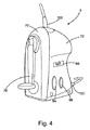
図4は、水処理システム5を示す。図解された実施例では、水処理システム5は、そのシステムに水を供給する吸入口101、システムから水を分配するための排水口103、及び、水処理システム5に電気を供給するための充電クランク76を有する。ケース70、及び、正面72は、水処理システム5を収納するためのハウジングを形成する。本発明の水処理システム5は、手動で充電可能であり、そのシステムに充電するための外部電源を必要としない。
水制御スイッチ94は、システム10を介した水の加圧を制御する。
FIG. 4 shows the water treatment system 5. In the illustrated embodiment, the water treatment system 5 has an
Water control switch 94 controls the pressurization of water through
図5は、水処理システム5の分解組立図である。フラッシュライト72は、水処理システム5の他の要素に独立して使用可能である。ケース70は、耐水性プラスチックで構成される。正面72は、空洞74を含む。クランク76は、使用しない場合、クランク空洞74の中に収納されるのが好ましい。クランク76は、歯車80を係合するためのポート78を介してはめ込まれる。反射体88は、UVランプ83の出力に対するUV透過リアクタの露出を増加させるために、UVランプ83の周りにはめ込まれる。
FIG. 5 is an exploded view of the water treatment system 5. The
充電器82は、発電機84に接続される。充電器82は、壁コンセント、太陽電池、又は、バッテリのような、外部AC又はDC電源に対して接続可能である。発電機84は、手動で発電可能な発電機である。クランク76は、発電機84に操作的に、係合される。発電機84は、ハチンソンのUS特許番号6,133,642、及び、ハチンソン等のUS特許番号6,472,846で開示されるような、通常の手動充電器で良く、それらは、ここでの参照により全体として同一のものとされる。あるいは、発電機は、手動クランクはもちろんのこと、足を使って動かすものであっても良い。
The
クランク76をまわせば、クランク76は、発電機84に動力を伝える。ある実施例では、発電機84は、充電器82に電荷を移動させ、次に、充電器82は、バッテリ86を充電する。別な実施例では、発電機84は、そのシステムに直接的に電気を供給するために使用される。クランク76は、使用後、クランク空洞74に戻される。あるいは、これらの電源システムの各々は、水処理システムから離れて使用される。別な実施例では、クランク76は、動力ポンプ104に機械的に使用される。
If the
図6を参照すると、ケース70は、フィルタ102、ポンプ104、コイル92、及びUVランプ83を含む。フィルタ102は、カーボンフィルタのような、水から汚染物質を取り除くことも可能である。水は、フィルタ102から、ポンプ104へ、パイプ105を経由して移動する。ポンプ104は、異なる操作流量速度を有する。
Referring to FIG. 6, the
コイル92は、ポンプ104に直接接続され、又は、増設チューブによりポンプ104に接続しても良い。コイル92は、UVランプ83の周辺に配置されるのが好ましい。コイル92は、ソフトグラス、クウォーツ、又は、(テフロン(登録商標)として良く知られている)ポリテトラフルオロエチレンのようなUV透過材料で構成される。図5に示される反射体88は、コイル92の中で、UVランプ83からの光に対する水の露出を増加するために使用される。
The
UVランプ83は、バラスト90に接続される。コントローラ108は、バラスト90に接続され、かつ、UVランプ83への給電を制御する。システムを介して通る水を制御するために、コントローラ108は、ポンプ104にも接続される。コントローラ108は、フラッシュライト72に接続しても良い。
The
コントローラ108は、ケース70に配置される水制御スイッチ94及び光スイッチ96に接続されるのが好ましい。スイッチ94、96は、ユーザによる2つ以上の操作モード間の選択を可能にする。スイッチ94、96は、複数の操作モード間で切り替えられる。
例えば、システム5は、夜間照明、又は、緊急点滅装置としても付加的に操作可能である。
The
For example, the system 5 can additionally be operated as night lighting or an emergency flashing device.
コントローラ108は、フラッシュライト72、ポンプ104、充電器82、及び、UVランプ83間に、適切に電気を分配するようにプログラムされるのが好ましい。コントローラ108は、全てのデバイスに必要な電気を分配することが可能であり、それらの優先順位に基づいて上記のデバイスに給電可能である。
水制御スイッチ94は、コントローラ108に信号を送り、そして、次に、コントローラ108は、水を加圧するために、ポンプ104に信号を送る。同様に、光スイッチ96は、少なくとも「オン」ポジション及び「オフ」ポジションを有する。フラッシュライト72は、複数の光、又は、フラッシュモードのようなモードを含む場合、光スイッチ96は、これらの代替機能を作動させるポジションを有する。
The water control switch 94 sends a signal to the
フラッシュライト72は、光制御回路に接続される。光制御回路は、フラッシュモードのような、複数のモードで光110に電気を供給するようにプログラムされている。あるいは、光制御回路は、複数の光に電気を供給する。
吸入口チューブ101は、嵐、沼、湖、川、又は、水を含んだシンクやバスタブのような他のいかなる水源にも配置される。ポンプ104は、吸入口チューブ101を介してフィルタ102に水を引き込む。ポンプは、吸入口チューブの中、又は、末端に配置しても良い。フィルタ102は、水から汚染物質を取り除く。それから、水は、UVランプ83からUV光に対して露出しながら、コイル92を通って加圧される。UVランプは、水の中のバクテリア及び微生物を殺傷する。
The
The
ポンプ104が、可変速度である場合、ユーザは、水制御スイッチ94を用いてポンプ流量を選択する。水は、排水口チューブ103を介して、排出される。
If the
上記は、好ましい実施例である。様々な代替案及び変更は、添付の請求項で定義される発明の精神及びより広げた形態から離れることなく行うことが可能である。そしてそれは、均等論を含む特許法の原則にしたがって同一のものとされる。例えば、「ある(a)」、「ある(an)」、「前記(the)」、「前記(said)」という記載を用いた単数形における請求項の構成は、その単数形に関する構成に制限するものではないことを考慮するべきである。
また、排他権又は特権が請求される本発明の実施例は、特許請求の範囲で定義される。
The above is a preferred embodiment. Various alternatives and modifications can be made without departing from the spirit and broader forms of the invention as defined in the appended claims. And it will be the same according to the principles of patent law including the doctrine of equivalents. For example, the configuration of a claim in the singular using the phrases “a”, “an”, “the”, “said” is limited to configurations related to the singular You should consider what you do not do.
Also, embodiments of the invention in which an exclusive right or privilege is claimed are defined in the claims.
Claims (32)
前記水処理システムを通して水を移送するポンプと、
紫外光透過リアクタと、
前記水に照射するための紫外光ランプと、
前記ポンプ及び前記紫外光ランプに給電するバッテリと、
前記バッテリを充電するための手動発電機と、
前記ポンプ、前記バッテリ、及びバッテリ充電監視回路に接続されるコントローラと、を有し、
前記コントローラが前記バッテリ充電監視回路から情報を受信することによって、前記バッテリが前記紫外光ランプを所望の強度にするための十分な電力を有しない場合、前記コントローラは、前記ポンプに給電することを禁止する水処理システム。 A water treatment system,
A pump for transferring water through the water treatment system;
An ultraviolet light transmission reactor,
An ultraviolet lamp for irradiating the water;
A battery for supplying power to the pump and the ultraviolet lamp;
A manual generator for charging the battery;
A controller connected to the pump, the battery, and a battery charge monitoring circuit;
When the controller receives information from the battery charge monitoring circuit, the controller powers the pump if the battery does not have sufficient power to bring the ultraviolet lamp to the desired intensity. Prohibit water treatment system.
UVランプと、
前記処理サブシステム処理部に給電するバッテリと、
前記ハウジング内に収容され、かつ、前記バッテリに接続される充電器と、
前記バッテリに接続されるバッテリ充電監視回路と、
前記バッテリを充電するために前記充電器に接続される手動発電機と、
前記充電器に接続され、かつ、前記水処理システムの運転を管理するコントローラと、
前記コントローラに接続され、かつ、前記UVランプを監視するためのランプセンサと、
前記コントローラに接続され、かつ、前記水処理システムを通して水を移送するポンプと、を有し、
前記コントローラは、前記バッテリ充電監視回路から受信した情報に応答して、前記充電器から前記バッテリに電気を選択的に供給する水処理システム。 A water treatment system having a housing and a treatment subsystem treatment part included in the housing, wherein the treatment subsystem treatment part comprises:
A UV lamp,
A battery for supplying power to the processing subsystem processing unit;
A charger housed in the housing and connected to the battery;
A battery charge monitoring circuit connected to the battery;
A manual generator connected to the charger to charge the battery ;
A controller connected to the charger and managing the operation of the water treatment system;
A lamp sensor connected to the controller and for monitoring the UV lamp;
It is connected to the controller, and has a pump for transferring water through the water treatment system,
The controller is a water treatment system that selectively supplies electricity from the charger to the battery in response to information received from the battery charge monitoring circuit.
前記水処理システムを通して水を移送する電気ポンプと、
フィルタ、UVランプ、及び、UV透過リアクタを含み、前記UVランプによって水を処理することができる電気水処理サブシステムと、
前記電気ポンプ及び前記電気水処理サブシステムに電気的に接続される蓄電デバイスと、
前記蓄電デバイスを充電するための手動発電機と、
前記電気水処理サブシステム、前記電気ポンプ、及び前記蓄電デバイスに接続されるコントローラであって、前記蓄電デバイスを介して前記電気ポンプ及び前記電気水処理サブシステムを選択的に給電するコントローラと、
を有する水処理システム。 A water treatment system,
An electric pump for transferring water through the water treatment system;
An electrical water treatment subsystem that includes a filter, a UV lamp, and a UV transmission reactor, and is capable of treating water with the UV lamp;
An electricity storage device electrically connected to the electric pump and the electric water treatment subsystem;
A manual generator for charging the electricity storage device;
A controller connected to the electric water treatment subsystem, the electric pump, and the electricity storage device, wherein the controller selectively supplies power to the electric pump and the electric water treatment subsystem via the electricity storage device;
Having a water treatment system.
前記ハウジング内にあり、かつ、UVランプを含むUV透過リアクタと、
前記UV透過リアクタを通して水を加圧することが可能であり、かつ、前記UV透過リアクタに接続される電気ポンプと、
前記電気ポンプ及び前記UVランプに接続されるバッテリと、
前記ハウジング内に収納され、前記バッテリに接続され、かつ、手動操作によって前記バッテリに電圧を加える手動発電機と、
前記バッテリから前記UVランプ及び前記ポンプに選択的に給電することによって、水処理システムの運転を調整するコントローラと、
を有する水処理システム。 A housing;
A UV transmission reactor in the housing and including a UV lamp;
An electric pump capable of pressurizing water through the UV transmission reactor and connected to the UV transmission reactor;
A battery connected to the electric pump and the UV lamp;
A manual generator housed in the housing, connected to the battery and applying a voltage to the battery by manual operation;
A controller that regulates the operation of the water treatment system by selectively powering the UV lamp and the pump from the battery;
Having a water treatment system.
前記ランプセンサは、前記コントローラに接続される請求項28に記載の水処理システム。 A lamp sensor for monitoring the UV lamp;
The water treatment system according to claim 28, wherein the lamp sensor is connected to the controller.
前記コントローラは、前記UVランプの前記運転特性に応じて、前記ポンプを運転するようにプログラムされている請求項31に記載の水処理システム。 The lamp sensor provides information to the controller regarding the operating characteristics of the UV lamp;
32. The water treatment system of claim 31, wherein the controller is programmed to operate the pump according to the operating characteristics of the UV lamp.
Applications Claiming Priority (3)
| Application Number | Priority Date | Filing Date | Title |
|---|---|---|---|
| US10/869,515 | 2004-06-16 | ||
| US10/869,515 US7306716B2 (en) | 2004-06-16 | 2004-06-16 | Water treatment system |
| PCT/IB2005/051584 WO2005123601A1 (en) | 2004-06-16 | 2005-05-16 | A water treatment system |
Publications (3)
| Publication Number | Publication Date |
|---|---|
| JP2008502471A JP2008502471A (en) | 2008-01-31 |
| JP2008502471A5 JP2008502471A5 (en) | 2008-07-03 |
| JP5410675B2 true JP5410675B2 (en) | 2014-02-05 |
Family
ID=34972670
Family Applications (1)
| Application Number | Title | Priority Date | Filing Date |
|---|---|---|---|
| JP2007516080A Expired - Fee Related JP5410675B2 (en) | 2004-06-16 | 2005-05-16 | Water treatment system |
Country Status (12)
| Country | Link |
|---|---|
| US (2) | US7306716B2 (en) |
| EP (1) | EP1756009B1 (en) |
| JP (1) | JP5410675B2 (en) |
| KR (1) | KR101268164B1 (en) |
| CN (1) | CN1968896B (en) |
| AT (1) | ATE450477T1 (en) |
| CA (1) | CA2564828C (en) |
| DE (1) | DE602005018052D1 (en) |
| ES (1) | ES2335423T3 (en) |
| PL (1) | PL1756009T3 (en) |
| RU (1) | RU2385295C2 (en) |
| WO (1) | WO2005123601A1 (en) |
Families Citing this family (28)
| Publication number | Priority date | Publication date | Assignee | Title |
|---|---|---|---|---|
| SE526093C2 (en) * | 2002-11-22 | 2005-07-05 | Dometic Ab | Liquid supply system |
| US7306716B2 (en) * | 2004-06-16 | 2007-12-11 | Access Business Group International Llc | Water treatment system |
| US7490516B2 (en) * | 2006-01-26 | 2009-02-17 | Rosemount Inc. | Manual powered process transmitter |
| RU2433086C2 (en) * | 2006-05-01 | 2011-11-10 | Конинклейке Филипс Электроникс Н.В. | Self-contained water treatment device |
| WO2008064180A1 (en) * | 2006-11-17 | 2008-05-29 | Miox Corporation | Water purification system |
| RU2352625C1 (en) * | 2007-07-04 | 2009-04-20 | Общество С Ограниченной Ответственностью "Евростандарт" | Device for processing and distillation of liquid product |
| US7862728B2 (en) * | 2007-09-27 | 2011-01-04 | Water Of Life, Llc. | Ultraviolet water purification system |
| US8529770B2 (en) * | 2007-09-27 | 2013-09-10 | Water Of Life, Llc. | Self-contained UV-C purification system |
| US20090208386A1 (en) * | 2007-10-23 | 2009-08-20 | Barsky Barry E | Germicidal water purification unit |
| US7883619B2 (en) * | 2007-11-13 | 2011-02-08 | Access Business Group International Llc | Water treatment system with moisture detector |
| KR20170072356A (en) * | 2009-01-12 | 2017-06-26 | 액세스 비지니스 그룹 인터내셔날 엘엘씨 | Point-of-use water treatment system |
| NZ594012A (en) | 2009-01-13 | 2013-01-25 | Access Business Group Int Llc | A gravity fed water treatment system comprising a foam filter element, a biological layer and a restriction orifice to limit the flow of water through the system |
| US20100314551A1 (en) * | 2009-06-11 | 2010-12-16 | Bettles Timothy J | In-line Fluid Treatment by UV Radiation |
| US8282880B2 (en) * | 2009-08-12 | 2012-10-09 | Neverest Travel Solutions | Bottle, system and method for sterilizing a liquid |
| WO2011084892A1 (en) | 2010-01-08 | 2011-07-14 | Hydro-Photon, Inc. | Dynamo powered ultraviolet water purification system |
| US20110174993A1 (en) * | 2010-01-18 | 2011-07-21 | Camelbak Products, Llc | Water purifying drink containers |
| US8872130B1 (en) * | 2012-03-19 | 2014-10-28 | Meridian Design, Inc. | UVC water purifier system and method |
| US9084949B2 (en) * | 2011-02-24 | 2015-07-21 | Western New England University | Water purification system |
| USD707124S1 (en) | 2012-04-02 | 2014-06-17 | Camelbak Products, Llc | Bottle cap |
| WO2013181455A1 (en) | 2012-05-30 | 2013-12-05 | Robert Gellibolian | Water bottle with flow meter |
| JP5969824B2 (en) * | 2012-06-01 | 2016-08-17 | ホーチキ株式会社 | Smoke testing machine |
| US8975596B1 (en) * | 2012-07-20 | 2015-03-10 | Meridian Design, Inc. | Water purifying drink containers |
| WO2015008289A1 (en) * | 2013-07-17 | 2015-01-22 | Advant-Hatch Ltd. | Water purification system |
| CN107922229A (en) | 2015-05-22 | 2018-04-17 | 捷通国际有限公司 | Place to use formula water treatment system |
| WO2020055780A1 (en) | 2018-09-11 | 2020-03-19 | Access Business Group International Llc | Water treatment system with vacuum filtration |
| CN112919699A (en) | 2019-12-06 | 2021-06-08 | 捷通国际有限公司 | Water treatment system |
| US11667550B2 (en) * | 2020-04-30 | 2023-06-06 | Arizona Board Of Regents On Behalf Of Arizona State University | Photoelectrocatalytic device for water disinfection |
| RU204740U1 (en) * | 2020-10-27 | 2021-06-08 | федеральное государственное бюджетное образовательное учреждение высшего образования «Томский государственный университет систем управления и радиоэлектроники» | DEVICE FOR WATER DISINFECTION BY UV RADIATION |
Family Cites Families (57)
| Publication number | Priority date | Publication date | Assignee | Title |
|---|---|---|---|---|
| GB1421804A (en) * | 1973-08-29 | 1976-01-21 | Te Hsiung Wu | Portable electrically operated devices |
| US4017735A (en) | 1975-10-24 | 1977-04-12 | Siegel Arthur D | Ultraviolet liquid sterilizer |
| US4274970A (en) * | 1979-10-29 | 1981-06-23 | Beitzel Stuart W | Method and apparatus for treating water |
| US4625119A (en) | 1985-04-10 | 1986-11-25 | Murdock Iii James O | Sanitizer for bathroom articles |
| US4740706A (en) | 1985-04-10 | 1988-04-26 | Murdock Laboratories, Inc. | Sanitizer for bathroom articles |
| US4849100A (en) | 1986-03-07 | 1989-07-18 | North American Aqua | Portable water purifier |
| US4755292A (en) | 1986-08-11 | 1988-07-05 | Merriam Theodore D | Portable ultraviolet water sterilizer |
| US4909931A (en) | 1987-12-17 | 1990-03-20 | Tana - Netiv Halamed-He Industries | Water-purifier device |
| US5008548A (en) | 1989-08-01 | 1991-04-16 | Nahum Gat | Personal UV radiometer |
| US4969991A (en) | 1989-08-30 | 1990-11-13 | Valadez Gerardo M | Water purifying and dispensing system |
| US5585112A (en) | 1989-12-22 | 1996-12-17 | Imarx Pharmaceutical Corp. | Method of preparing gas and gaseous precursor-filled microspheres |
| US5147532A (en) | 1991-02-21 | 1992-09-15 | Leek Jr Kenneth F | Domestic grey water purifier using diverter and UV filter treater with preheater |
| US5106495A (en) | 1991-07-12 | 1992-04-21 | Harold Hughes | Portable water purification device |
| US5618662A (en) | 1992-03-02 | 1997-04-08 | Cerus Corporation | Intravenous administration of psoralen |
| US5459030A (en) | 1992-03-02 | 1995-10-17 | Steritech, Inc. | Synthetic media compositions for inactivating bacteria and viruses in blood preparations with 8-methoxypsoralen |
| US5709991A (en) | 1992-03-02 | 1998-01-20 | Cerus Corporation | Proralen inactivation of microorganisms and psoralen removal |
| US5653877A (en) | 1992-12-09 | 1997-08-05 | Fm Mark Electronics Incorporated | Water purification system having multi-pass ultraviolet radiation and reverse osmosis chambers |
| US5393419A (en) | 1993-02-10 | 1995-02-28 | Amway Corporation | Ultraviolet lamp assembly for water purification |
| US5324423A (en) | 1993-02-11 | 1994-06-28 | Amway Corporation | UV bulb intensity control for water treatment system |
| US5536395A (en) | 1993-03-22 | 1996-07-16 | Amway Corporation | Home water purification system with automatic disconnecting of radiant energy source |
| US5266215A (en) | 1993-04-27 | 1993-11-30 | Rolf Engelhard | Water purification unit |
| US5366705A (en) | 1993-06-08 | 1994-11-22 | James J. Reidy | Gravity feed ultraviolet liquid sterilization system |
| US5484538A (en) | 1993-09-14 | 1996-01-16 | Texavia International, Inc. | Multiple service water purifier and dispenser and process of purifying water |
| US5445729A (en) | 1993-10-07 | 1995-08-29 | Premier Manufactured Systems, Inc. | Counter top reverse osmosis system |
| US5466425A (en) | 1994-07-08 | 1995-11-14 | Amphion International, Limited | Biological decontamination system |
| US5591978A (en) | 1994-07-27 | 1997-01-07 | Alvin Kovalsky | All wavelength ultraviolet intensity monitor |
| WO1996009776A1 (en) | 1994-09-27 | 1996-04-04 | Purepulse Technologies, Inc. | Photocatalyst and pulsed light synergism in deactivation of contaminants |
| US5676824A (en) | 1994-09-30 | 1997-10-14 | Samsung Electronics Co., Ltd. | Water purifier with means for indicating when filter replacement is due and for automatically initiating a membrane washing step |
| US5567311A (en) | 1994-11-14 | 1996-10-22 | Samsung Electronics Co., Ltd. | Water purifier with electrical components isolated from leaked water |
| US5628895A (en) | 1995-03-08 | 1997-05-13 | Zucholl; Klaus | Closed circuit for treating drinking water with UV treatment and filtering |
| US5611918A (en) | 1995-08-02 | 1997-03-18 | Amway Corporation | Electronic driver for water treatment system UV bulb |
| JPH09122654A (en) * | 1995-09-01 | 1997-05-13 | Toray Ind Inc | Drinking water production apparatus |
| US5874741A (en) | 1995-10-03 | 1999-02-23 | Matschke; Arthur L. | Apparatus for germicidal cleansing of water |
| US5843309A (en) | 1995-10-13 | 1998-12-01 | Puragua, Inc. | Water purification system |
| US5785845A (en) | 1995-11-09 | 1998-07-28 | Colaiano; Robert | Water purifying system |
| US5837197A (en) | 1995-12-22 | 1998-11-17 | Personal Fertility Technologies, Inc. | Positive fertility testing and reproductive health system |
| JPH09220558A (en) * | 1996-02-16 | 1997-08-26 | Kurashino Joho Center:Kk | Water purifier |
| US5720304A (en) | 1996-03-01 | 1998-02-24 | Omura; Yoshiaki | Method of treatment of some resistant infections, cancer and other diseases which have infection and localized metal deposits in pathological areas |
| US5814212A (en) | 1996-03-11 | 1998-09-29 | Hsu; Chao Fou | Monitoring process and device for an activated carbon filtration system of drinking water |
| US6182453B1 (en) | 1996-04-08 | 2001-02-06 | Worldwide Water, Inc. | Portable, potable water recovery and dispensing apparatus |
| GB2312175B (en) | 1996-04-17 | 2000-03-01 | Keith Raymond Dalton | A portable container for purifying drinking water |
| US5776339A (en) | 1996-07-29 | 1998-07-07 | Samsung Electronics Co., Ltd. | Water purifier having purified water storage tank and valve for discharging purified water before reaching the tank |
| US5900212A (en) | 1997-01-27 | 1999-05-04 | Hydro-Photon, Inc. | Hand-held ultraviolet water purification system |
| FR2780718B1 (en) * | 1998-05-22 | 2000-09-01 | Cythelia | DEVICE FOR CONTROLLING WATER POTABILIZATION SYSTEMS WITHOUT CHEMICAL ADDITION |
| US6099735A (en) * | 1998-06-04 | 2000-08-08 | Kelada; Maher I. | Counter top reverse osmosis water purification system |
| GB9824773D0 (en) * | 1998-11-11 | 1999-01-06 | Baygen Power Ind Limited | Power source |
| US6139726A (en) | 1998-12-29 | 2000-10-31 | Uv Cooling Technologies | Treated water dispensing system |
| FR2790818B3 (en) | 1999-03-09 | 2001-02-23 | Pui Hing Tsui | LUMINOUS RIBBON-LIKE DECORATIVE STRUCTURE |
| WO2000071227A1 (en) * | 1999-05-21 | 2000-11-30 | Life Spring Limited Partnership | User-activated ultra-violet water treatment unit |
| US6451202B1 (en) | 1999-06-21 | 2002-09-17 | Access Business Group International Llc | Point-of-use water treatment system |
| US6380711B2 (en) * | 1999-06-30 | 2002-04-30 | Research In Motion Limited | Battery recharging device and method and an automatic battery detection system and method therefor |
| GB9916292D0 (en) | 1999-07-13 | 1999-09-15 | Hozelock Ltd | Filter assemblies |
| US6264836B1 (en) * | 1999-10-21 | 2001-07-24 | Robert M. Lantis | Method and apparatus for decontaminating fluids using ultraviolet radiation |
| CA2499683C (en) * | 2002-09-26 | 2012-06-19 | Hydro-Photon, Inc. | Uv led based water purification module for intermittantly operable flow-through hydration systems |
| US6863827B2 (en) * | 2002-12-09 | 2005-03-08 | Daniel Saraceno | Solar powered portable water purifier |
| WO2005040046A2 (en) * | 2003-10-20 | 2005-05-06 | Lawrence Allen Bernstein | A manually operable water purifying device |
| US7306716B2 (en) * | 2004-06-16 | 2007-12-11 | Access Business Group International Llc | Water treatment system |
-
2004
- 2004-06-16 US US10/869,515 patent/US7306716B2/en not_active Expired - Fee Related
-
2005
- 2005-05-16 KR KR1020127009534A patent/KR101268164B1/en not_active IP Right Cessation
- 2005-05-16 WO PCT/IB2005/051584 patent/WO2005123601A1/en active Application Filing
- 2005-05-16 EP EP20050747366 patent/EP1756009B1/en not_active Not-in-force
- 2005-05-16 DE DE200560018052 patent/DE602005018052D1/en active Active
- 2005-05-16 JP JP2007516080A patent/JP5410675B2/en not_active Expired - Fee Related
- 2005-05-16 PL PL05747366T patent/PL1756009T3/en unknown
- 2005-05-16 RU RU2007100936A patent/RU2385295C2/en not_active IP Right Cessation
- 2005-05-16 AT AT05747366T patent/ATE450477T1/en active
- 2005-05-16 CA CA 2564828 patent/CA2564828C/en not_active Expired - Fee Related
- 2005-05-16 CN CN2005800199781A patent/CN1968896B/en not_active Expired - Fee Related
- 2005-05-16 ES ES05747366T patent/ES2335423T3/en active Active
-
2007
- 2007-10-26 US US11/924,885 patent/US20080041775A1/en not_active Abandoned
Also Published As
| Publication number | Publication date |
|---|---|
| RU2007100936A (en) | 2008-07-27 |
| JP2008502471A (en) | 2008-01-31 |
| US20080041775A1 (en) | 2008-02-21 |
| ES2335423T3 (en) | 2010-03-26 |
| PL1756009T3 (en) | 2010-05-31 |
| CN1968896A (en) | 2007-05-23 |
| EP1756009A1 (en) | 2007-02-28 |
| CA2564828A1 (en) | 2005-12-29 |
| KR101268164B1 (en) | 2013-05-27 |
| CN1968896B (en) | 2012-01-18 |
| US20050279679A1 (en) | 2005-12-22 |
| KR20120057648A (en) | 2012-06-05 |
| EP1756009B1 (en) | 2009-12-02 |
| DE602005018052D1 (en) | 2010-01-14 |
| RU2385295C2 (en) | 2010-03-27 |
| CA2564828C (en) | 2011-08-30 |
| WO2005123601A1 (en) | 2005-12-29 |
| US7306716B2 (en) | 2007-12-11 |
| ATE450477T1 (en) | 2009-12-15 |
Similar Documents
| Publication | Publication Date | Title |
|---|---|---|
| JP5410675B2 (en) | Water treatment system | |
| US6579495B1 (en) | Hand-held ultraviolet water purification system using solid state devices | |
| AU2003275209B2 (en) | UV led based water purification module for intermittantly operable flow-through hydration systems | |
| JP2008502471A5 (en) | ||
| US20150053624A1 (en) | Portable water purification system using one or more low output power uv light sources | |
| JP3238818B2 (en) | Water purifier and electric circuit used for same | |
| JP5384328B2 (en) | Water purification device that functions autonomously | |
| ATE548330T1 (en) | MINIATURIZED FLUID TREATMENT SYSTEM WITH OWN POWER SUPPLY | |
| JP2012081427A (en) | Sterilizer and water purifier equipped therewith | |
| KR20070022095A (en) | A water treatment system | |
| US20170291831A1 (en) | Uv reflective system including a thin plastic coated aluminum reflector or a thin plastic removable bladder | |
| US20110168642A1 (en) | Dynamo powered ultraviolet water purification system | |
| CN107188349A (en) | Water purifier | |
| KR200295117Y1 (en) | Silver-ion water apparatus for public bath | |
| JP2003190952A (en) | System for producing electrolytic water |
Legal Events
| Date | Code | Title | Description |
|---|---|---|---|
| A521 | Request for written amendment filed |
Free format text: JAPANESE INTERMEDIATE CODE: A523 Effective date: 20080515 |
|
| A621 | Written request for application examination |
Free format text: JAPANESE INTERMEDIATE CODE: A621 Effective date: 20080515 |
|
| A131 | Notification of reasons for refusal |
Free format text: JAPANESE INTERMEDIATE CODE: A131 Effective date: 20110830 |
|
| A521 | Request for written amendment filed |
Free format text: JAPANESE INTERMEDIATE CODE: A523 Effective date: 20111028 |
|
| A131 | Notification of reasons for refusal |
Free format text: JAPANESE INTERMEDIATE CODE: A131 Effective date: 20120724 |
|
| A521 | Request for written amendment filed |
Free format text: JAPANESE INTERMEDIATE CODE: A523 Effective date: 20120820 |
|
| A131 | Notification of reasons for refusal |
Free format text: JAPANESE INTERMEDIATE CODE: A131 Effective date: 20130319 |
|
| A601 | Written request for extension of time |
Free format text: JAPANESE INTERMEDIATE CODE: A601 Effective date: 20130618 |
|
| A602 | Written permission of extension of time |
Free format text: JAPANESE INTERMEDIATE CODE: A602 Effective date: 20130625 |
|
| A521 | Request for written amendment filed |
Free format text: JAPANESE INTERMEDIATE CODE: A523 Effective date: 20130912 |
|
| A01 | Written decision to grant a patent or to grant a registration (utility model) |
Free format text: JAPANESE INTERMEDIATE CODE: A01 Effective date: 20131008 |
|
| A61 | First payment of annual fees (during grant procedure) |
Free format text: JAPANESE INTERMEDIATE CODE: A61 Effective date: 20131107 |
|
| LAPS | Cancellation because of no payment of annual fees |