JP5410097B2 - Optical fiber cable having dry insert and method of manufacturing the same - Google Patents
Optical fiber cable having dry insert and method of manufacturing the same Download PDFInfo
- Publication number
- JP5410097B2 JP5410097B2 JP2008554220A JP2008554220A JP5410097B2 JP 5410097 B2 JP5410097 B2 JP 5410097B2 JP 2008554220 A JP2008554220 A JP 2008554220A JP 2008554220 A JP2008554220 A JP 2008554220A JP 5410097 B2 JP5410097 B2 JP 5410097B2
- Authority
- JP
- Japan
- Prior art keywords
- cable
- ribbon
- dry insert
- optical fiber
- cavity
- Prior art date
- Legal status (The legal status is an assumption and is not a legal conclusion. Google has not performed a legal analysis and makes no representation as to the accuracy of the status listed.)
- Expired - Fee Related
Links
Images


Classifications
-
- G—PHYSICS
- G02—OPTICS
- G02B—OPTICAL ELEMENTS, SYSTEMS OR APPARATUS
- G02B6/00—Light guides; Structural details of arrangements comprising light guides and other optical elements, e.g. couplings
- G02B6/44—Mechanical structures for providing tensile strength and external protection for fibres, e.g. optical transmission cables
- G02B6/4479—Manufacturing methods of optical cables
- G02B6/4483—Injection or filling devices
-
- G—PHYSICS
- G02—OPTICS
- G02B—OPTICAL ELEMENTS, SYSTEMS OR APPARATUS
- G02B6/00—Light guides; Structural details of arrangements comprising light guides and other optical elements, e.g. couplings
- G02B6/44—Mechanical structures for providing tensile strength and external protection for fibres, e.g. optical transmission cables
- G02B6/4401—Optical cables
- G02B6/4429—Means specially adapted for strengthening or protecting the cables
- G02B6/443—Protective covering
- G02B6/4432—Protective covering with fibre reinforcements
- G02B6/4433—Double reinforcement laying in straight line with optical transmission element
-
- G—PHYSICS
- G02—OPTICS
- G02B—OPTICAL ELEMENTS, SYSTEMS OR APPARATUS
- G02B6/00—Light guides; Structural details of arrangements comprising light guides and other optical elements, e.g. couplings
- G02B6/44—Mechanical structures for providing tensile strength and external protection for fibres, e.g. optical transmission cables
- G02B6/4401—Optical cables
- G02B6/4429—Means specially adapted for strengthening or protecting the cables
- G02B6/44384—Means specially adapted for strengthening or protecting the cables the means comprising water blocking or hydrophobic materials
-
- G—PHYSICS
- G02—OPTICS
- G02B—OPTICAL ELEMENTS, SYSTEMS OR APPARATUS
- G02B6/00—Light guides; Structural details of arrangements comprising light guides and other optical elements, e.g. couplings
- G02B6/44—Mechanical structures for providing tensile strength and external protection for fibres, e.g. optical transmission cables
- G02B6/4401—Optical cables
- G02B6/4403—Optical cables with ribbon structure
Description
本発明は、概略的には、光導波路の乾式包装(ドライパッケージング)に関する。本発明は、詳細には、少なくとも1本の光導波路を保護するための少なくとも1本のドライインサート(dry insert)を有する通信システム用オプティカルアセンブリに関する。 The present invention generally relates to dry packaging of optical waveguides. More particularly, the present invention relates to an optical assembly for a communication system having at least one dry insert for protecting at least one optical waveguide.
光ファイバケーブルは、光信号、例えば音声、映像及び(又は)データ情報を伝送する光導波路、例えば光ファイバを有する。光ファイバケーブルの形態の一タイプは、チューブ内に納められた光導波路を有し、それにより、チューブ組立体が形成される。一般的に言って、チューブは、光導波路を保護するが、光導波路は、チューブ内で一段と保護されなければならない。例えば、光導波路は、ベンディング(曲げ)に順応するようチューブとの間で或る程度の相対運動を生じる必要がある。他方、光導波路は、チューブに適切に結合されるべきであり、それにより、例えば引張力を及ぼしてケーブルを布設する際に光導波路がチューブ内で変位するのが阻止される。さらに、チューブ組立体は、この中への水の侵入を阻止する必要がある。さらに、チューブ組立体は、過度の光学性能の劣化を生じさせないで、或る温度範囲にわたって動作できることが必要である。 Optical fiber cables have optical waveguides, such as optical fibers, that transmit optical signals, such as audio, video, and / or data information. One type of fiber optic cable form has an optical waveguide housed in a tube, thereby forming a tube assembly. Generally speaking, the tube protects the optical waveguide, but the optical waveguide must be further protected within the tube. For example, the optical waveguide needs to produce some relative motion with the tube to accommodate bending. On the other hand, the optical waveguide should be properly coupled to the tube, thereby preventing the optical waveguide from being displaced within the tube, for example when laying the cable by applying a tensile force. In addition, the tube assembly needs to prevent water from penetrating into it. In addition, the tube assembly needs to be able to operate over a range of temperatures without causing excessive optical performance degradation.
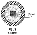
従来型光チューブ組立体は、チューブをチキソトロープ物質、例えばグリースで満たすことによりこれら要件を満足させている。チキソトロープ物質は一般に、光導波路とチューブとの間の適度の運動、緩衝及び光導波路の結合を可能にする。さらに、チキソトロープ物質は、チューブ内への水の流入を止めるのに有効である。しかしながら、光導波路のコネクタ接続前に、チキソトロープ物質を光導波路からきれいに取り除かなければならない。チキソトロープ物質を光導波路から取り除くことは、厄介で時間のかかるプロセスである。さらに、チキソトロープ物質の粘度は一般に、温度依存性である。粘度の変化により、チキソトロープ物質は、比較的高温でチューブの端からしたたり落ちる場合があり、又、チキソトロープ物質は、比較的低温で光減衰を引き起こす場合がある。 Conventional light tube assemblies meet these requirements by filling the tube with a thixotropic material, such as grease. Thixotropic materials generally allow moderate motion between the optical waveguide and the tube, buffering and coupling of the optical waveguide. In addition, thixotropic substances are effective in stopping the inflow of water into the tube. However, the thixotropic material must be cleanly removed from the optical waveguide before connecting the optical waveguide connector. Removing thixotropic material from an optical waveguide is a cumbersome and time consuming process. Furthermore, the viscosity of thixotropic materials is generally temperature dependent. Due to the change in viscosity, the thixotropic material may drip off the end of the tube at a relatively high temperature, and the thixotropic material may cause light attenuation at a relatively low temperature.
ケーブルの設計において、チキソトロープ物質をチューブから無くすことが試みられたが、この設計は、これら設計が上述の要件の全てを満たしてはいないので、全体として不適切であると共に(或いは)製造費が高くつく。チキソトロープ物質をチューブから無くした1つの例は、米国特許第4,909,592号明細書に開示された発明であり、この米国特許明細書は、従来型吸水膨張性テープ及び(又は)収納状態のヤーンを有するチューブを開示している。例えば、従来型吸水膨張性テープは、典型的には、吸水膨張性粉末をサンドイッチした2つの薄手の不織層から形成され、それにより、バッファチューブ内部の空間を充填することはない比較的薄手のテープが形成される。その結果、従来型吸水膨張性テープは、非充填空間があるので、光導波路にとって適切な結合をもたらしていない。さらに、この空間により、チューブ内の水が、従来型吸水膨張性テープによって閉じこめられないで、チューブに沿って移動しうる。このため、この設計では、チューブ内に、光ファイバとチューブを適切に結合するための多数の吸水膨張性コンポーネントが必要である。さらに、バッファチューブ内に多数の吸水膨張性コンポーネントを用いることは、そのことによりケーブルのコストと共に製造上の複雑さが増大するので、経済的ではない。 In cable designs, attempts have been made to eliminate thixotropic material from the tube, but this design is inadequate and / or costly to manufacture as these designs do not meet all of the above requirements. It is expensive. One example of thixotropic material being removed from the tube is the invention disclosed in US Pat. No. 4,909,592, which is a conventional water-swellable tape and / or storage condition. A tube having the following yarns is disclosed. For example, a conventional water-swellable tape is typically formed from two thin nonwoven layers sandwiched with water-swellable powders, thereby relatively thin without filling the space inside the buffer tube. The tape is formed. As a result, conventional water-absorbable expandable tape does not provide adequate coupling for the optical waveguide due to the unfilled space. Furthermore, this space allows the water in the tube to move along the tube without being confined by the conventional water-absorbing expandable tape. For this reason, this design requires a number of water-swellable components in the tube to properly couple the optical fiber and the tube. Furthermore, using a large number of water-swellable components in the buffer tube is not economical because it increases the manufacturing complexity with the cost of the cable.
チキソトロープ物質を光ファイバケーブルから無くした別の例は、米国特許第6,278,826号明細書に開示された発明であり、この米国特許は、ゼロよりも多い含水量又は率を有し、超吸収性ポリマーが装填されたフォームを開示している。フォームの含水量は、フォームの難燃性を向上させるものとして説明されている。これと同様に、この設計のフォームは、比較的高価であり、ケーブルのコストを増大させる。 Another example of eliminating thixotropic material from a fiber optic cable is the invention disclosed in US Pat. No. 6,278,826, which has a water content or rate greater than zero, Disclosed is a foam loaded with a superabsorbent polymer. The water content of the foam is described as improving the flame retardancy of the foam. Similarly, this form of design is relatively expensive and increases the cost of the cable.
次に、本発明の好ましい実施形態を示す添付の図面を参照して本発明を以下に詳細に説明する。しかしながら、本発明は、多くの種々の形態で実施でき、本明細書に記載する実施形態に限定されるものと解釈されてはならず、それどころか、これら実施形態は、開示により本発明の範囲が当業者に十分に理解されるように提供されている。図面は、必ずしも縮尺通りではなく、本発明を明確に示すよう作成されている。 The present invention will now be described in detail with reference to the accompanying drawings, which illustrate preferred embodiments of the invention. This invention may, however, be embodied in many different forms and should not be construed as limited to the embodiments set forth herein; rather, these embodiments will fall within the scope of the invention by disclosure. It is provided so that it can be fully understood by those skilled in the art. The drawings are not necessarily to scale, but are drawn to clearly illustrate the present invention.
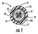
本発明の一特徴による例示のチューブ組立体10が図1に示されている。チューブ組立体10は、少なくとも1本の光導波路12、例えば光ファイバと、少なくとも1つのドライインサート14と、チューブ18とを有する。この場合、少なくとも1本の光導波路12は、リボン13のスタックの形態をしており、このスタックは、スタックのコーナー部相互間のさしわたりの対角線寸法Dを有している。ドライインサート14は、少なくとも1本の光導波路12を全体的に包囲していて、このドライインサートは、チューブ18内に納められたコア15を形成している。ドライインサート14は、例えば、緩衝、結合、水の流入の阻止(止水)のような機能を実行し、曲げに順応する。ドライインサート14は、コネクタ接続前に取り除き又はクリーニングを必要とする残滓又はフィルムを後に残さないで光導波路をドライインサートから容易に取り外すことができるので有利である。さらに、従来型チキソトロープ物質とは異なり、ドライインサート14は、温度が変化しても粘性が変わらず又は高温でチューブの端からしたたり落ちる又は滴下する傾向がない。さらに、チューブ組立体10は、ドライインサート14を光導波路12周りに保持する他の適当なコンポーネント、例えばバインダポリエステル糸17を有するのが良い。これと同様に、ドライインサート14をこれらの周りにチューブ18を押出し成形する前に互いに保持するために2本又は3本以上の糸を互いに縫い合わせるのが良い。図1aは、チューブ組立体10の変形例であるチューブ組立体10′を示している。具体的に説明すると、チューブ組立体10′は、対角線寸法Dを備えた24本のルース光導波路12を含むが、任意適当な本数の光導波路を使用できる。さらに、光導波路12をバインダ、吸水膨張性糸、テープ、包装材又は他の適当な材料を用いて1つ又は2つ以上のグループの状態に束ねるのが良い。さらに、チューブ組立体10又は10′は、図5に示すようなケーブルの一部であっても良い。さらに、本発明のドライインサート14をチューブレス設計のケーブルに用いることができる。
An
図示のように、光導波路12は、光ファイバリボンの一部をなす光ファイバである。この場合、光導波路は、リボンスタック13を形成するリボンフォーマットの複数本のシングルモード光ファイバである。リボンスタック13は、螺旋撚り又はS−Z撚りを有するのが良い。さらに、他形式又は他形態の光導波路を用いても良い。例えば、光導波路12は、マルチモードファイバ、ピュアモードファイバ、エルビウムドープファイバ、偏波面維持ファイバ、他の適当なタイプの光導波路及び(又は)これらの組合せであって良い。さらに、光導波路12は、ルース型であっても良く、バンドル型であっても良い。各光導波路12は、シリカ又は石英を主成分とするコアを有するのが良く、このコアは、光信号を伝えることができ、コアよりも屈折率の低いシリカを主成分とする被覆材によって包囲されている。さらに、1つ又は2つ以上の被膜を光導波路12に被着させるのが良い。例えば、軟質の一次被膜が、被覆材を包囲し、比較的硬質の二次被膜が、一次被膜を包囲する。一実施形態では、1本又は2本以上の光導波路12は、2003年7月18日に出願された米国特許出願第10/632,219号明細書に開示されている被覆システムを有し、この米国特許出願を参照により引用し、その開示内容を本明細書の一部とする。光導波路12は、識別手段、例えばインキ又は識別のための他の適当な標識を更に有するのが良い。当然のことながら、光導波路は、タイトバッファ層を更に有するのが良い。適当な光ファイバは、ニューヨーク州コーニング所在のコーニング・インコーポレイテッド(Corning Incorporated)から市販されている。
As illustrated, the
他の実施形態では、リボンスタック13は、所定のMAC数を備えたコーナー光導波路12aを有するのが良く、それにより、圧縮力を受けたときのコーナー光導波路の光減衰が阻止される。換言すると、所定のMAC数を備えたコーナー光導波路を選択することにより、圧縮力に起因する光減衰の影響を受けにくい光導波路が、比較的高いレベルの圧縮を受けるリボンスタック場所に配置される。他の実施形態では、リボンの光導波路12の全ては、所定のMAC数を有するのが良い。本明細書において用いる「MAC数」は、モードフィールズ直径(MFD)を所与の光導波路12aに関するカットオフ波長で割って算出したものであり、この場合、両方の量は、マイクロメートルで表され、したがってMAC数は、無次元である。換言すると、MFDは一般に、マイクロメートルで表され、カットオフ波長は、一般に、ナノメートルで表され、したがって、カットオフ波長を1000で割ってこれをマイクロメートルに変換しなければならず、それにより、無次元の数が得られる。
In other embodiments, the
一例を挙げると、MAC数は、約7.35以下、より好ましくは約7.00以下、最も好ましくは約6.85以下であるが、MAC数には、下限がある。一例を挙げると、コーナー光導波路12aは、MFDが9.11μm以下、カットオフ波長が1240nm以上であり、それにより得られるMAC数が7.35以下となるように選択されている。一般的に言って、MAC数は、MFDに正比例し、カットオフ波長に反比例する。リボンスタック13は、4本のコーナー光導波路12aを有するが、他の形態のリボンスタックは、これ以上のコーナー位置を有しても良い。例えば、全体として符号がプラスの形状を持つリボンスタックは、8つの外側コーナーを有する。これと同様に、他の形態のリボンスタックは、これとは異なる数のコーナー位置を有しても良い。
In one example, the MAC number is about 7.35 or less, more preferably about 7.00 or less, and most preferably about 6.85 or less, but the MAC number has a lower limit. As an example, the corner optical waveguide 12a is selected so that the MFD is 9.11 μm or less, the cutoff wavelength is 1240 nm or more, and the resulting MAC number is 7.35 or less. Generally speaking, the number of MACs is directly proportional to the MFD and inversely proportional to the cutoff wavelength. The
さらに、本発明のリボン実施形態は、正のリボン余長(ERL)を有するのが良い。ただし、或るケーブル設計では、負のERLが可能であるが、一般的に言えば、性能に悪影響が生じる。本明細書で用いる“ERL”は、特定のリボンの長さからリボンを収容したチューブ又はケーブルの長さを引いてリボンを収納したチューブ又はケーブルの長さで除算したものとして定義され、これは、100を乗算することにより百分率として表現できる。チューブ長を用いてERLを計算するか、ケーブル長を用いてERLを計算するかは、特定の形態で決まる。さらに、ケーブルの個々のリボンは、互いに異なる値のERLを有していても良い。一例を挙げると、ケーブルのリボンは、正のERL、好ましくは、約0.0%〜約0.4%以上の正のERLを有するが、他の適当な値が可能な場合がある。同様に、ルース型又はバンドル型光ファイバを有する実施形態は、ケーブルの形態に取って適当な範囲内に収まる正のファイバ余長(EFL)を有するのが良い。 Further, the ribbon embodiments of the present invention may have a positive ribbon surplus length (ERL). However, some cable designs allow negative ERLs, but generally speaking, performance is adversely affected. As used herein, “ERL” is defined as the length of a particular ribbon, minus the length of the tube or cable containing the ribbon, divided by the length of the tube or cable containing the ribbon, , 100 and can be expressed as a percentage. Whether the ERL is calculated using the tube length or the ERL using the cable length depends on the specific form. Furthermore, the individual ribbons of the cable may have different values of ERL. By way of example, cable ribbons have a positive ERL, preferably from about 0.0% to about 0.4% or more, although other suitable values may be possible. Similarly, embodiments having loose or bundled optical fibers may have a positive fiber surplus length (EFL) that falls within the appropriate range for cable configuration.
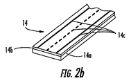
図2は、例示のドライインサート14の断面図である。ドライインサート14は、製造中、連続用途のためにリールから繰出し可能な1つ又は2つ以上の細長い材料で形成されている。ドライインサート14を互いに異なる機能を実行できる複数の層で形成しても良いが、ドライインサートは、圧縮可能な単一の層、例えばフェルト材料であるのが良く、また、オプションとして、止水/吸水膨張性特徴を備えるのが良い。ドライインサート14は、光導波路12をチューブ18から緩衝し、それにより、光導波路12の光減衰度を1310nmの基準波長では約0.4dB/km以下に、1550nm及び1625nmの基準波長では0.3dB/km以下に維持する。しかしながら、1550nm及び1625nmの基準波長についてはそれぞれ例えば0.35/0.25の他の適当な光減衰度が可能である。一実施形態では、ドライインサート14は、2つの別々の層で作られる。例えば、図2は、圧縮可能な層であるドライインサート14の第1の層14a及び吸水膨張性層である第2の層14bを示している。この場合、第1の層14aは、適度の結合特性をもたらす所定のばね定数を持つ圧縮可能な材料で作られる。一例を挙げると、第1の層は、フォームテープ、好ましくは連続気泡フォームテープであるが、任意適当な圧縮可能な材料、例えば独立気泡フォームテープを使用しても良い。図2に示すように、第2の層14bは、任意適当な構造のものであって良く、好ましい実施形態では、1つ又は2つ以上のコンポーネントを有する適当な吸水膨張性テープである。例えば、吸水膨張性テープは、図2の2つの互いに異なる細部を示す引出し円によって示されているように、互いに異なる構造を有しても良いが、一般に、少なくとも1つのテープ、例えば、複数個の吸水膨張性粒子14eを有する不織テープ14fを有する。しかしながら、ドライインサート14は、1種類又は2種類以上の材料で作られた他形式の粒子を有しても良い。
FIG. 2 is a cross-sectional view of an exemplary
第1の層14aと第2の層14bは好ましくは、接着剤14dによって互いに取り付けられ、これら層を分離するには約5ニュートン以上の力が必要であるようになっている。接着剤14dを製造中、層のうち一方又は両方に吹き付けるのが良く、それにより接着剤のクラスタが生じるのを阻止する微細なミストが作られるようにするのが良いが、他の適当な塗布方法も又可能である。しかしながら、接着剤は、1つ又は2つ以上の層に塗布される他の形態、例えば粉末のものであっても良い。用いられる接着剤の形態がどのようなものであれ、ドライインサートが光導波路の周りに配置されたときに、これが減衰レベルの増大を生じさせてはならない。同様に、吸水膨張性粒子又は団塊状粒子、例えば接着剤及び(又は)吸水膨張性粒子は、マイクロベンディングを引き起こしてはならない。換言すると、接着剤14d又は他の団塊状材料、例えば接着剤と吸水膨張性粉末の平均粒径は、比較的小さいもの、例えば、600ミクロン以下、好ましくは約450ミクロン以下、最も好ましくは約300ミクロン以下であるべきであり、したがって、粒子がドライインサート14の一部を通って光導波路に当たった場合でも、これら粒子は、マイクロベンディングレベルを増大させないようになっている。本明細書で用いる「平均粒径」という用語は、ドライインサート14に用いられる1種類又は2種類以上の物質の粒子を意味している。
The
図2の右側の細部を示す引出し円内に示すように、第2の層14bは、2つの不織テープ状材料14f相互間に設けられた吸水膨張性粒子14eを有する吸水膨張性テープであり、この第2の層14bは、接着剤14dにより第1の層14aに取り付けられている。この構造は、粒子がマイクロベンディングを生じさせるのを阻止する。というのは、不織テープが第1の層14aと吸水膨張性粒子14eとの間でバッファとして働くからである。吸水膨張性粉末の平均粒径は、比較的小さく、例えば、600ミクロン以下、好ましくは約450ミクロン以下、最も好ましくは約300ミクロン以下であるべきであり、したがって、粒子がドライインサート14の一部を通って光導波路に当たった場合でも、これら粒子は、マイクロベンディングレベルを増大させないようになっている。第2の層14bは、例えば図2の左側の詳細を示す引出し円内に示すような他の構造を有しても良い。具体的に説明すると、この実施形態は、単一の不織テープ14fの片面に取り付けられた吸水膨張性粒子14eを示しており、次に、この単一の不織テープ14fは、圧縮可能な第1の層14aに取り付けられて吸水膨張性粒子14eがバッファ層無しで第1の層と第2の層との間に配置されるようにする。この構造では、接着剤14fは、吸水膨張性粒子14eを取り付けると共にドライインサート14の第1の層14aと第2の層14bを互いに取り付けるよう機能する。しかしながら、ドライインサート14のこの構造により、一般に、接着剤及び吸水膨張性粒子で形成された団塊状材料の平均粒径が大きくなる。換言すると、全てが等しいとすれば、このドライインサート構造の平均粒径は、一般的に大きい。というのは、これにより、吸水膨張性粒子それだけと比較して、団塊状粒子が生じるからである。その結果、これにより、平均粒径が大きすぎるようになった場合、マイクロベンディングの増大が生じる場合がある。そこで、この構造では、団塊状粒子又は複合粒子の平均粒径は、マイクロベンディングを阻止する上では上述したのと同一の範囲にあるべきである。
As shown in the drawing circle showing the details on the right side of FIG. 2, the
同様に、ドライインサート14の内面は、マイクロベンディングレベルを増大させてはならない。この結果、好ましい実施形態では、光導波路に接触可能な層の表面は、比較的滑らかな表面であるべきである。例えば、フォームがドライインサート14の第1の層14aとして用いられる場合、フォームの平均的な気泡サイズは、約1000ミクロン以下、より好ましくは約700ミクロン以下であり、それにより、比較的滑らかな表面が得られる。さらに、フォームは、サイズが互いに異なる気泡、例えば、光導波路から見て遠くに位置する気泡が大きく、光導波路に接触することができるフォームの表面の近くの気泡が小さい層を有するのが良い。他の変形例は、フォーム層の表面を平滑化するための表面処理が施される。表面処理としては、表面を平滑化するための加熱又は気泡を適当な材料で充填することが挙げられる。さらに、第1の層14a、例えばフォームは、ドライインサート14の吸水膨張性粒子及び(又は)接着剤がマイクロベンディングを生じさせないよう緩衝作用をもたらす。
Similarly, the inner surface of the
一実施形態では、第1の層は、連続気泡ポリウレタン(PU)フォームテープである。PUフォームテープは、エーテル系PUかエステル系PUかのいずれかであるのが良いが、他の適当なフォームテープでは、圧縮可能な層、例えばポリエチレンフォーム、ポリプロピレンフォーム又はEVAフォームを用いても良い。しかしながら、好ましい実施形態では、エーテル系フォームテープが用いられる。というのは、このエーテル系フォームテープは、湿気を受けたときにエステル系PUフォームよりも良好に働くからである。換言すると、エステル系PUフォームは、水分で分解する場合があり、これに対し、エーテル系PUフォームは、一般的に、水分に対して強い。さらに、フォーム層は、約1lb/ft3〜約3lb/ft3(1.1kg/m3〜3.3kg/m3)の所定の密度を有するが、好ましい実施形態では、この密度は、約2lb/ft3(2.2kg/m3)である。ドライインサート14は、製造中の破断を阻止するよう所定の極限引張強度を更に有する。一般的に言って、ドライインサートが圧縮可能な層と吸水膨張性層の両方を有している状態では、引張強度の大部分は、吸水膨張性層によって提供される。ドライインサートの極限引張強度は好ましくは、ドライインサート14の1cm幅W当たり約20ニュートン以上であり、より好ましくは、ドライインサート14の1cm幅W当たり約30ニュートン以上である。
In one embodiment, the first layer is an open cell polyurethane (PU) foam tape. The PU foam tape may be either ether-based PU or ester-based PU, but other suitable foam tapes may use compressible layers, such as polyethylene foam, polypropylene foam or EVA foam. . However, in a preferred embodiment, ether-based foam tape is used. This is because this ether-based foam tape works better than ester-based PU foam when subjected to moisture. In other words, ester-based PU foam may decompose with moisture, whereas ether-based PU foam is generally resistant to moisture. Furthermore, the foam layer has a predetermined density of about 1 lb / ft 3 ~ about 3lb / ft 3 (1.1kg / m 3 ~3.3kg / m 3), in a preferred embodiment, the density is about 2 lb / ft 3 (2.2 kg / m 3 ). The
ドライインサート14は好ましくは、吸水膨張性物質の膨張高さの大部分が水にさらされて約120秒以内に、より好ましくは約90秒以内に生じるような吸水膨張速度を有する。一例を挙げると、ドライインサート14は、非制限的膨張状態では、蒸留水に関し、約18mm、5%イオン性水溶液、即ち塩水に関し約8mmの最大膨張高さを有するが、他の適当な最大膨張高さを有するドライインサートを使用しても良い。チューブ組立体は、吸水膨張比が約3以上、より好ましくは約5以上、最も好ましくは約7以上の状態に構成される。吸水膨張比は、ドライインサートの非制限的膨張状態の断面積をチューブ組立体中の自由空間で除算したものと定義される。丸形ケーブルの場合、チューブ組立体の自由空間は、チューブの内径の領域から光導波路が占める領域を引いたものとして定義される。例えば、ドライインサートが50mm2の非制限的膨張状態断面積を有し、チューブが10mm2の自由空間を有している場合、吸水膨張比は、5である。
The
ドライインサート14を組立ての際に圧縮して、光導波路12かチューブ18に沿って長手方向に容易にずらされるのを阻止する所定の通常の力がこのドライインサートによって生じるようにするのが良い。ドライインサート14は、好ましくは、チューブ直径及び(又は)ケーブル直径を最小限に抑えるために約5mm以下の非圧縮高さhを有するが、ドライインサート14について任意適当な高さhを用いても良い。さらに、ドライインサート14の高さhは、幅全体にわたり一定である必要はなくて様々であって良く、それにより、光導波路の断面形状への形状適合が行われて緩衝作用が向上し、それにより光学性能が向上する(図10)。第2の層14bは、チューブ18内への水の侵入を阻止する吸水膨張性層、例えばテープである。
The
ドライインサート14の圧縮は、実際には、ドライインサート14の局所最大圧縮である。図1の場合、ドライインサート14の局所最大圧縮は、直径を横切ってリボンスタックの隅又はコーナー部のところで生じる。図18に示されているような他のケーブル設計では、以下に説明するように、ドライインサートの局所最大圧縮は、一般に、波状に起伏したリボンスタックの最大振幅度のところで生じる。図1のドライインサート14の圧縮度の割合を計算するには、チューブ18の内径、リボンスタックの対角線寸法D及びドライインサート14の非圧縮高さhを知る必要がある。一例を挙げると、チューブ18の内径は、7.1mmであり、リボンスタックの対角線寸法Dは、5.1mmであり、直径を横切るドライインサート14の非圧縮高さhは、3.0mm(2×1.5mm)である。対角線寸法D(5.1mm)及び直径を横切るドライインサート14の非圧縮高さh(3.0mm)を加えることにより、8.1mmの非圧縮寸法が得られる。リボンスタック及びドライインサート14を内径が7.1mmのチューブ18内に配置すると、ドライインサートは、全部で1mm(8.1mm−7.1mm)圧縮される。この結果、ドライインサート14は、チューブ18の直径を横切って約30%圧縮される。
The compression of the
図2aは、3つの互いに異なるドライインサート14に関する例示の圧縮曲線200,202,204を示すグラフ図である。具体的に説明すると、曲線200,202は、各々が圧縮可能な連続気泡エーテル系PUフォーム層及び吸水膨張性層を有する2つの互いに異なるドライインサートを表している。曲線200,202はそれぞれ、高さhが約1.5mm、約1.8mmのドライインサートを表している。他方、曲線204は、圧縮可能な連続気泡エステル系PUフォーム層及び吸水膨張性層を有し、高さが約1.8mmのドライインサートを表している。圧縮曲線を得るのに、インストロン(Instron)機を用いてドライインサートサンプルを圧縮するのに必要な力を測定しながらドライインサートサンプルを直径が約2.2インチ(5.6mm)の2枚の円形のプレート相互間に配置した。
FIG. 2 a is a graphical diagram illustrating exemplary compression curves 200, 202, 204 for three different
図示のように、3つ全てのドライインサート14に関する圧縮曲線は、圧縮範囲全体として非直線状である。しかしながら一般的に言って、圧縮曲線200,202,204は、最大約0.70mmまでの全体として直線圧縮状態を有する。一実施形態では、ドライインサート14は、約10ニュートンの力で約10.0mm以下の圧縮度を有する。一般的に言って、フォーム層は、吸水膨張性層が比較的非圧縮性である間、圧縮されている。 他の実施形態では、ドライインサート14の第1の層14aは、チューブ組立体10内では非圧縮状態であるが、光導波路の運動が開始された場合に圧縮を開始する。他の変形例としては、ドライインサート14の一部をチューブ18に取り付け又は結合することが挙げられる。例えば、接着剤、グルー、エラストマー及び(又は)ポリマー14cは、ドライインサート14をチューブ18に取り付けるためにチューブ18に接触しているドライインサート14の表面の一部に施される。例えば、層14cは、チューブ18の押出し成形中、少なくとも部分的に溶けるポリマー層であり、それにより層14cとチューブ18との間に結合部が作られる。さらに、ドライインサート14を、長手方向に配置するのではなく、光導波路12に螺旋に巻き付けることが可能である。さらに別の実施形態では、2つ又は3つ以上のドライインサートを1本又は2本以上の光導波路12の周りに形成しても良く、例えば、2つの半部がチューブ18内に配置される。
As shown, the compression curves for all three
他の実施形態は、ケーブルコア15及び(又は)ドライインサート14をチューブ18内に結合するのに用いられる一過性グルー/接着剤を含むのが良い。グルー/接着剤等は、例えば製造プロセス中、ドライインサート14の半径方向外向きの表面に塗布される。一過性グルー/接着剤は、高温状態にある間にドライインサート14の外面に塗布され又はこの外面に融着され、そしてケーブルが急冷され又は冷えたときに冷却され又は凍らされる。一例を挙げると、適当な一過性グルーは、ニュージャージー州ブリッジウォータ所在のナショナル・スターチ・アンド・ケミカル・カンパニー(National Starch and Chemical Company)からLITE−LOK(登録商標)70−003Aという商品名で入手できる。一過性グルー又は他の適当な接着剤/物質を図2b〜図2dに示すような連続又は間欠的形態を有するビードの状態で塗布するのが良い。例えば、1つ又は2つ以上の接着剤/グルービードをドライインサートに沿って長手方向に塗布し、長手方向に間隔を置いたビードの状態で塗布し、ドライインサートの長手方向軸線に沿ってジグザグのビードの状態で塗布し、又は任意他の適当な形態で塗布しても良い。
Other embodiments may include a temporary glue / adhesive used to bond the
一用途では、一過性グルー/接着剤等の複数個のビードが、ドライインサート14に塗布される。例えば、3つの連続した又は非連続的なビードを、ドライインサートがリボンスタックの周りに形成されたときに、これらビードが約120°の間隔を置くような場所に設けるのが良い。これと同様に、4つのビードを、ドライインサートが光導波路周りに形成されたときに、これらが約90°の間隔を置くような場所に設けるのが良い。長手方向軸線に沿って互いに間隔を置いて設けられたビードを有する実施形態では、ビードは、約20mm〜約800mm以上の長手方向間隔Sを有するのが良いが、他の適当な間隔を使用しても良い。さらに、必要な材料の量を最小限に抑えるためにビードを間欠的に塗布するのが良く、それにより、製造費が減少する一方で、依然として十分な結合/付着が得られる。
In one application, a plurality of beads such as temporary glue / adhesive are applied to the
チューブ組立体10は、チキソトロープ物質で満たされていないので、チューブは、変形し又は潰れる場合があり、それにより、丸形のチューブではなく、楕円形の形をしたチューブが形成される。2003年5月30日に出願された米国特許出願第10/448,509号明細書は、チューブが所定の平均楕円度(長円度)を有するバイモーダルポリマー材料(bimodal polymeric material)から作られたドライチューブ組立体を記載しており、この米国特許出願を参照により引用し、その開示内容を本明細書の一部とする。本明細書で用いる「楕円度」という用語は、チューブ18の長軸直径D1と短軸直径D2の差を長軸直径D1で除算してから100倍した値であり、それにより、楕円度が百分率として表される。バイモーダルポリマー材料は、少なくとも比較的高分子量の第1のポリマー材料及び比較的低分子材料の第2のポリマー材料を含む材料をデュアルリアクタ(dual reactor)法で製造したものを含む。このデュアルリアクタ法は、所望の材料特性をもたらし、このデュアルリアクタ法は、単純ポストリアクタ法(simple post reactor )と混同されるべきではなく、この単純ポストリアクタ法は、ポリマー配合物中の両方の樹脂の特性を損なう。一実施形態では、チューブの平均楕円度は、約10%以下である。一例を挙げると、チューブ18は、ミシガン州ミッドランド所在のダウ・ケミカル・カンパニー(Dow Chemical Company)からDGDA−2490NTという商品名で入手できるHDPEから形成される。
Since the
図3は、種々の形態のチューブ及びケーブルについて標準化された光リボン引抜き力(N/m)を示す棒グラフ図である。リボン引抜き力試験により、長さ10メートルのケーブルからリボンスタックの動きを開始させるのに必要な力を測定した。当然のことながら、この引抜き力試験は、同じようにルース又はバンドル型光導波路に当てはまる。具体的に説明すると、リボンのスタックをチューブから引き抜き、動きを開始させるのに必要な力をケーブルの長さで除算し、それにより光リボン引抜き力を標準化した。比較のためのベースラインとして、棒30は、従来型グリース(チキソトロープ物質)充填チューブ(図11)内に納められた120本のファイバ(120心)から成るリボンスタックに関して約4.8N/mのリボン引抜き力を示している。棒31は、チューブ内にルースに納められた144心のリボンスタック(図12)周りに吸水膨張性テープを有するだけの従来型ドライチューブ設計に関するリボン引抜き力を示している。具体的に説明すると、棒31は、144心リボンスタックに関して約0.6N/mのリボン引抜き力を示している。この結果、従来設計のドライチューブ(図12)は、従来型グリース充填チューブ(図11)のリボン引抜き力の約12%のリボン引抜き力を有し、これは、適切なケーブル性能を得るには不適切である。 FIG. 3 is a bar graph showing optical ribbon pull-out force (N / m) standardized for various forms of tubes and cables. The ribbon pull-out force test measured the force required to initiate ribbon stack movement from a 10 meter long cable. Of course, this pull-out force test applies equally to loose or bundled optical waveguides. Specifically, the ribbon stack was pulled from the tube and the force required to initiate movement was divided by the length of the cable, thereby standardizing the optical ribbon pulling force. As a baseline for comparison, rod 30 is about 4.8 N / m for a ribbon stack of 120 fibers (120 cores) housed in a conventional grease (thixotropic material) filled tube (FIG. 11). The ribbon pull-out force is shown. Bar 31 shows the ribbon pulling force for a conventional dry tube design that only has a water-swellable tape around a 144 core ribbon stack (FIG. 12) housed loosely in the tube. Specifically, bar 31 exhibits a ribbon pulling force of about 0.6 N / m for a 144 core ribbon stack. As a result, the conventionally designed dry tube (FIG. 12) has a ribbon pulling force that is about 12% of the ribbon pulling force of the conventional grease filled tube (FIG. 11), which is necessary for proper cable performance. It is inappropriate.
棒32,34,36,38は、本発明のチューブ組立体を示し、棒39は、図18に示すケーブル180を示している。具体的に説明すると、棒32は、ドライインサート14の圧縮率が約0%の状態で、非圧縮高さhが約1.5mmのドライインサート14を有するチューブ組立体10からの144心スタックのリボン引抜き力を示している。この実施形態では、棒32は、約1.0N/mのリボン引抜き力を示しており、これは、従来型ドライチューブと比較して驚くべき改良結果である。棒34,36は、ドライインサート14がチューブ組立体10内でその元の高さから平均圧縮高さまで1%だけ圧縮された形態を示している。具体的に説明すると、棒34は、この実施形態では、ドライインサート14が約30%圧縮されていることを除き、棒32とほぼ同じチューブ組立体のリボン引抜き力を示している。この実施形態では、棒34は、約2.7N/mのリボン引抜き力を示している。棒36は、非圧縮高さhが約3mmのドライインサート14を含むチューブ組立体からの144心リボンスタックのリボン引抜き力を示しており、このドライインサートは、チューブ内で約30%だけ圧縮されている。この実施形態では、棒36は、約0.5N/mのリボン引抜き力を示している。棒38は、ドライインサート14及びグルービードの圧縮率が約17%の状態で、非圧縮高さhが約1.5mmのドライインサート14を含むチューブ組立体10からの144心スタックのリボン引抜き力を示している。この場合、4つのグルービードをドライインサートに沿って長手方向に連続して塗布してこれらが約90°の間隔を置いて位置するようにした。この実施形態に関するリボン引抜き力は、約4.0N/mであった。図示のように、接着剤/グルービードの塗布により、ドライインサートの圧縮率が低い状態でリボン引抜き力が増大した。この結果、本発明の技術的思想によれば、ドライインサート14の圧縮率は、約10%〜約90%であるのが良いが、圧縮率が他の適当な範囲であっても又は圧縮率がゼロであっても、所望の性能をもたらすことができる。それにもかかわらず、ドライインサート14の圧縮率は、光導波路のうちのどれについても過度の光減衰を生じさせるほど大きいものであってはならず、接着剤/グルービードの使用により最適化できる。棒39は、以下に詳細に説明するように、ケーブル180のケーブルジャケット188からの4つの96心リボンスタックについて約1.5N/mのリボン引抜き力を示している。好ましくは、リボン引抜き力又は他の形態の光導波路に関する引抜き力は、約0.5N/m〜約5.0N/mであり、より好ましくは約1N/m〜約4N/mである。
Bars 32, 34, 36, and 38 show the tube assembly of the present invention, and bar 39 shows the
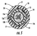
図4は、本発明のチューブ組立体10の例示の製造ライン40を概略的に示しているが、本発明の技術的思想の他の変形例を用いても本発明の技術的思想の他の組立体及び(又は)ケーブルを製造することができる。製造ライン40は、少なくとも1つの光導波路繰出しリール41と、ドライインサート繰出しリール42と、オプションとしての圧縮ステーション43と、グルー/接着剤ステーション43aと、結合ステーション44と、クロスヘッド押出機45と、水トラフ46と、巻取りリール49とを有している。さらに、チューブ組立体10の周りにはシース20が施されているのが良く、それにより、図5に示すようなケーブル50が形成される。シース20は、抗張力体(抗張力部材)19a及びジャケット19bを有するのが良く、これらは、チューブ組立体10と同一のラインで又は別の製造ラインで製造できる。例示の製造法は、少なくとも1本の光導波路12及びドライインサート14をそれぞれのリール41,42から繰り出すステップを有する。分かりやすくするために、光導波路12及びドライインサート14について繰出しリールが1つしか示されていないが、製造ラインは、本発明のチューブ組立体及びケーブルを製造するのに任意適当な数の繰出しリールを有することができる。次に、ドライインサート14を圧縮ステーション43で所定の高さhに圧縮し、オプションとしての接着剤/グルーをステーション43aでドライインサート14の外面に塗布する。次に、ドライインサート14を全体として光導波路12周りに位置決めし、所望ならば、結合ステーションにおいて、1本又は2本以上の結合糸をドライインサート14に巻き付け又はこの周りに縫い付け、それによりコア15を形成する。しかる後、コア15をクロスヘッド押出機45内に送り込み、ここで、チューブ18をコア15周りに押し出し、それによりチューブ組立体10を形成する。次に、チューブ18を水トラフ46内で急冷し、次にチューブ組立体10を巻取りリール49に巻き付ける。ボックスで示すように、一製造ラインがケーブル50を作るよう構成されている場合、抗張力体19aをリール47から繰り出し、チューブ18に隣接して位置決めし、クロスヘッド押出機48を用いてジャケット19bを抗張力体19a及びチューブ18の周りに押し出す。しかる後、ケーブル50を第2の水トラフ46に入れ、その後巻取りリール49に巻き付ける。さらに、本発明の技術的思想に従って他のケーブル及び(又は)製造ラインが可能である。例えば、ケーブル及び(又は)製造ラインは、チューブ18と抗張力体19aとの間に吸水膨張性テープ19c及び(又は)外装を有するのが良いが、他の適当なケーブルコンポーネントを使用することが可能である。
FIG. 4 schematically shows an
図6は、図3に用いたのとほぼ同じチューブ組立体を有するケーブルに関するリボン結合力の結果を示すグラフ図である。リボン結合力試験は、ケーブルに例えばケーブルの布設中引張作用を加えたときに光導波路に加えられる力をモデル化するために用いられる。リボン引抜き力とリボン結合力との間の結果は、同一の一般的範囲にある力を有する場合があるが、リボン結合力は一般に、実際のケーブル性能の良好な指標である。
この場合、リボン結合試験は、引張溝車をケーブル端部のそれぞれのシース上に配置することにより600ポンド(272kg)の引張力をケーブルの250m長さ分に加えることによりダクトに納めた状態の地下ケーブル布設をシミュレートしている。しかしながら、他のシミュレーションにおいてリボン結合状態を特徴付けるために、他の適当な荷重、長さ及び(又は)布設形態を使用することができる。次に、光導波路の長さに沿って光導波路に加わる力をケーブルの端から測定する。ブリルアン・オプティカル・タイム−ドメイン・レフレクトメータ(Brillouin Optical Time-Domain Reflectometer:BOTDR)を用いて光導波路に加わる力を測定する。曲線の最良適合勾配を求めることにより、リボン結合力が標準化される。
FIG. 6 is a graph showing the ribbon binding force results for a cable having substantially the same tube assembly used in FIG. The ribbon bonding force test is used to model the force applied to the optical waveguide when the cable is tensioned, for example, during cable laying. The result between the ribbon pull-out force and the ribbon bond force may have forces in the same general range, but the ribbon bond force is generally a good indicator of actual cable performance.
In this case, the ribbon bond test was performed by placing a tensioning groove on each sheath at the end of the cable and applying 600 pounds (272 kg) of tensile force to the 250 m length of the cable in the duct. Simulates underground cable installation. However, other suitable loads, lengths and / or laying configurations can be used to characterize ribbon bonding in other simulations. Next, the force applied to the optical waveguide along the length of the optical waveguide is measured from the end of the cable. The force applied to the optical waveguide is measured using a Brillouin Optical Time-Domain Reflectometer (BOTDR). By determining the best fit slope of the curve, the ribbon binding force is normalized.
比較のためのベースラインとして、曲線60は、従来型グリース充填チューブ(図11)内に納められた120本のファイバから成るリボンスタックを有するケーブルに関して約1.75N/mの標準化リボン結合力を示している。曲線62は、チューブ内にルースに納められた144本のファイバから成るリボンスタック周りに吸水膨張性テープを有する従来型ドライチューブ設計のケーブルに関するリボン引抜き力を示している。具体的に説明すると、曲線62は、144心リボンスタックに関して約0.15N/mの標準化リボン結合力を示している。この結果、従来設計のドライチューブ(図12)は、従来型グリース充填チューブ(図11)の標準化リボン結合力の約9%の標準化リボン結合力を有し、これは、適切なケーブル性能を得るには不適切である。換言すると、従来型ドライチューブケーブルのリボンスタックは、ケーブルシースの延伸中、例えば、架空雪、加重、架空ギャッロッピング、ケーブル掘り返し中やケーブル布設中の引張の際、変位しやすい。
As a baseline for comparison,
曲線64,66,68,69は、本発明のケーブルを示している。具体的に説明すると、曲線64は、ドライインサート14の圧縮率が約0%の状態で、非圧縮高さhが約1.5mmのドライインサート14を有するチューブ組立体10と、144心スタックを有するケーブルのリボン結合力を示している。この実施形態では、曲線64は、約0.80N/mのリボン結合力を示しており、これは、図12の従来型ドライケーブルと比較して改良結果を示している。曲線66,68は、ドライインサート14がチューブ組立体10内でその元の高さから平均圧縮高さまで1%だけ圧縮された形態を示している。具体的に説明すると、曲線66は、この実施形態では、ドライインサート14が約30%圧縮されていることを除き、曲線64とほぼ同じケーブルのリボン結合力を示している。この実施形態では、曲線66は、約2.80N/mのリボン結合力を示している。曲線68は、非圧縮高さhが約3mmのドライインサート14を含むチューブ組立体を有するケーブルと、144心リボンスタックを有するケーブルのリボン結合力を示しており、このドライインサートは、チューブ内で約30%だけ圧縮されている。この実施形態では、曲線68は、約0.75N/mのリボン結合力を示している。曲線69は、チューブ内で約17%圧縮され、接着剤/グルービードを有する非圧縮高さhが約1.5mmのドライインサート14を含むチューブ組立体10を有するケーブルと、144心スタックを有するケーブルのリボン結合力を示している。この場合、4つのグルービードをドライインサートに沿って長手方向に連続して塗布してこれらが約90°の間隔を置いて位置するようにした。図示のように、曲線69は、ドライインサートの圧縮率を少なくした状態で曲線66とほぼ同じリボン結合力、即ち、約2.80N/mを示している。このため、本発明の技術的思想によれば、リボン決抗力は、約0.5N/m〜約5.0N/mであり、より好ましくは約1N/m〜約4N/mである。しかしながら、他の適当な範囲のリボン結合力は、所望の性能をもたらすことができる。
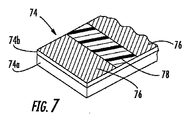
さらに、本発明の技術的思想は、ドライインサートの他の形態に利用できる。図7に示すように、ドライインサート74は、第1の層74a及び種々の適当な種類の吸水膨張性物質を含む第2の層74bを有している。一実施形態では、2つの互いに異なる吸水膨張性物質が、第2の層14内又はこの上に設けられ、チューブ組立体10が、多くの環境に関して有用であると共に向上した止水性能を有するようになっている。例えば、第2の層14bは、イオン化液、例えば塩水に有効な第1の吸水膨張性コンポーネント76及び非イオン化液に効果的な第2の吸水膨張性コンポーネント78を有するのが良い。一例を挙げると、第1の吸水膨張性材料は、ポリアクリルアミドであり、第2の吸水膨張性物質は、高吸水性ポリアクリレートである。さらに、第1及び第2の吸水膨張性コンポーネント76,78は、吸水膨張性テープの所定の部分を占めるのが良い。吸水膨張性材料を交互に配置することにより、テープは、標準的用途、塩水用途又はこれら両方に有用である。互いに異なる吸水膨張性物質の他の変形例としては、吸水膨張性物質に種々の膨張速度、ゲル強度及び(又は)テープとの付着性を与えることが挙げられる。
Furthermore, the technical idea of the present invention can be applied to other forms of dry inserts. As shown in FIG. 7, the
図8は、ドライインサートの別の実施形態を示している。ドライインサート84は、3つの層で作られる。層84a,84cは、結合力を少なくとも1本の光導波路に与えるよう圧縮可能である層84bをサンドイッチした吸水膨張性層である。これと同様に、ドライインサートの他の実施形態としては、例えば吸水膨張性層をサンドイッチした少なくとも2つの圧縮性層のような他の変形例が挙げられる。2つの圧縮可能な層は、少なくとも1本の光導波路に加えられる通常の力を個別調整するために互いに異なるばね定数を有するのが良い。
FIG. 8 shows another embodiment of the dry insert. The
図9は、本発明の別の実施形態の層94a,94bを有するドライインサート94を示している。層94aは、少なくとも1つの孔95が貫通して形成された独立気泡フォームで形成され、層94bは、少なくとも1つの吸水膨張性物質を含むが、圧縮可能な層に他の適当な材料を用いることができる。独立気泡フォームは、受動的な止水材料として働き、この受動的な止水材料は、水がこれに沿って侵入するのを阻止し、孔95により、層94bの活性化された吸水膨張性物質が、光導波路に向かって半径方向内方に移動することができる。活性化された吸水膨張性物質が半径方向内方に移動して溝を効果的に止めることができるようにする孔95の任意適当な寸法形状及び(又は)パターンが、許容可能である。孔の寸法形状及び(又は)パターンを選択してこれら穴をスタックのコーナー光導波路の周りに配置し、それにより、コーナー光導波路の性能を向上させることができる。例えば、孔95は、ドライインサートの圧縮性に変化を与えることができ、それにより、光学性能を維持するために光導波路に加えられる通常の力を個別調整できる。
FIG. 9 shows a
図10は、本発明の他の技術的思想を示したドライインサート104を示している。ドライインサート104は、層104a,104bを示している。層104aは、層104b上に設けられた複数個の非連続圧縮性要素で形成され、この層104bは、連続した吸水膨張性層である。一実施形態では、層104の要素は、リボンスタックの布設長さと全体として相関関係にある一定の間隔で配置される。さらに、これら要素は、これらの幅w全体にわたり変化する高さhを有する。換言すると、これら要素は、これが全体を包囲するようになった光導波路の形状に一致するよう形作られている。
FIG. 10 shows a
図13は、チューブ組立体10を採用している本発明の別の実施形態であるケーブル130を示している。ケーブル130は、チューブ組立体10の周りに設けられていて、チューブ組立体10を例えば圧潰力及び環境効果から保護するシースシステム137を有している。この場合、シースシステム137は、バインダ糸(見えず)により固定された吸水膨張性テープ132と、1対のリップコード135と、外装テープ136と、ジャケット138とを有している。外装テープ136は好ましくは、圧延成形されるが、他の適当な製造法を利用しても良い。1対のリップコード135は全体として、外装オーバーラップから約90°の間隔を置いて互いに約180°の間隔を置いて設けられ、それにより、使用中における外装テープの縁にリップコードの剪断作用が加わるのが阻止される。好ましい実施形態では、外装テープに裂け目を入れるのに適したリップコードは、2003年8月29日に出願された米国特許出願第10/652,046号明細書に開示されているような構造を有し、この米国特許出願を参照により引用し、その開示内容を本明細書の一部とする。外装テープ136は、誘電体か金属材料かのいずれかであるのが良い。誘電体外装テープが用いられる場合、ケーブルは、埋設用途においてケーブルの存在場所を突き止めるための金属製ワイヤを更に有するのが良い。換言すると、金属製ワイヤは、ケーブルをトーナブル(tonable )にする。ジャケット138は、外装テープ136を全体的に包囲し、ケーブル130に環境保護作用をもたらしている。当然のことながら、他の適当なシースシステムをチューブ組立体の周りに使用することができる。
FIG. 13 shows a
図14は、光ファイバケーブル140を示している。ケーブル140は、少なくとも1本の光導波路12及びシースシステム142内にケーブルコア141を形成するドライインサート14を有している。換言すると、ケーブル140は、ケーブルコア141への接近がシースシステム142を切断して開くことによってのみ達成されるのでチューブレス設計である。シースシステム142は、この中に埋め込まれていて、互いに約180°の間隔を置いて設けられた抗張力体142aを更に有し、それにより、優先的な曲がり部がケーブルに与えられている。当然のことながら、他の形態のシースシステム、例えば、抗張力体142aの種々のタイプ、量及び(又は)配置状態が可能である。ケーブル140は、ケーブルコア141とシース142との間に設けられ、シース142に裂け目を入れ、それによりケーブルコア141への技術者の容易な接近を可能にする1本又は2本以上のリップコード145を更に有するのが良い。
FIG. 14 shows an
図15は、中心部材151の周りに撚り合わされた複数本のチューブ組立体10を有する光ファイバケーブル150を示している。具体的に説明すると、チューブ組立体10は、複数本のフィラーロッド153と共に、中心部材151の周りにS−Zに撚られており、1本又は2本以上のバインダ糸(見えず)で固定され、それにより、撚りケーブルコアが形成されている。撚りケーブルコアの周りには、吸水膨張性テープ156が設けられ、この吸水膨張性テープは、ジャケット158がこの上に押し出される前にバインダ糸(見えず)で固定される。オプションとして、アラミド繊維、他の適当な抗張力体(及び)止水コンポーネント、例えば吸水膨張性ヤーンを中心部材151の周りに撚り合わせるのが良く、それにより撚りケーブルコアの一部が形成される。これと同様に、ケーブル150の昼間部に沿う水の侵入を阻止するために吸水膨張性コンポーネント、例えばヤーン又はテープを中心部材151の周りに配置するのが良い。ケーブル150の他の変形例は、外装テープ、内側ジャケット及び(又は)種々の本数のチューブ組立体を有しても良い。
FIG. 15 shows an
図16及び図17は、本発明の例示のチューブレス設計のケーブルを示している。具体的に説明すると、ケーブル160は、ジャケット168のキャビティ内でドライインサート14により全体が包囲された少なくとも1本の光導波路12を有するドロップケーブルである。ケーブル160は、少なくとも1本の抗張力体164を更に有する。他のチューブレスドロップケーブル形態、例えば、丸形の形態又は長円形の形態も又、可能である。図17は、共通ジャケット178により互いに連結されたメッセンジャー区分172とキャリヤ区分174を有するチューブレス8の字形ドロップケーブル170を示している。メッセンジャー部分172は、抗張力体173を有し、キャリヤ区分174は、キャリヤ区分174は、全体がドライインサート14により包囲された少なくとも1本の光導波路12が納められたキャビティを有する。キャリヤ区分174は、この中に設けられていて、キャリヤ区分174をメッセンジャー区分172から分離したときの収縮を阻止する少なくとも1本の座屈防止部材175を更に有するのが良い。図16及び図17は、図2のドライインサートを示しているが、任意適当なドライインサートを使用できる。
16 and 17 show an exemplary tubeless design cable of the present invention. Specifically, the
図18及び図18aは、それぞれ、全体として平べったい形状のチューブレスケーブル形態に本発明の技術的思想を採用したケーブル180,180′を示している。ケーブル180は、少なくとも1本の光導波路12及びケーブルジャケット188のキャビティ188a内に少なくとも部分的に収納された複数本のドライインサート184a,184bを有する。図示のように、ドライインサート184a,184bの主要な(例えば、平らな)表面(符号は付けられていない)は、全体として、キャビティ188aの主要な(例えば、水平の)表面(符号は付けられていない)と整列し、それにより、丸形チューブ内のリボンスタックの場合に生じるようなコーナー部におけるファイバ接触を一般に阻止した状態でコンパクト且つ効率的な形態の実現を可能にする。この実施形態では、光導波路12は、光ファイバリボン182(水平線によって表されている)の一部分であり、ドライインサート184a,184bは、複数本のリボン182を撚られていないスタックの状態にサンドイッチし、それによりケーブルコア185が形成されている。その結果、ケーブル180は、リボン182を有し、ドライインサート184a,184bの主要な表面及びキャビティ188aの主要な表面は、全体として整列し又は全体として平行である。さらに、ドライインサート184a,184bは、それぞれの頂部又は底部リボン182の少なくとも一部分に接触している。ケーブル180は、引っ張り強度をもたらすための少なくとも1本の抗張力体189を更に有し、この実施形態では、ケーブルは、キャビティ188aの互いに反対側に設けられた2本の抗張力体189を有している。抗張力体189を任意適当な材料、例えば、誘電体、導体、複合材等で作ることができる。ケーブル180は、2005年7月29日に出願された米国特許出願第11/193,516号明細書に開示されているような配線系ケーブルとして有利である。ケーブル180′は、ケーブル180に類似しているが、ドライインサート184a,184b相互間に設けられた6本のルース光ファイバ12(リボンの代わりに)を有している。この場合も又、光ファイバ12は、ドライインサート184a,184bのうちの一方の少なくとも一部分に接触している。当然のことながら、ケーブル180,180′及び他の類似のケーブルは、配線系ケーブルの他の用途、例えば、長距離用途、構内用途、引込み用途、屋内用途又は他の用途を有することができる。
FIGS. 18 and
リボン182は、24本の光ファイバを収容し、このリボンは、ケーブルジャケット188のキャビティ188a(図18b)内に少なくとも部分的に収納された複数本のリボン182により形成されたリボンスタック(符号は付けられていない)の一部分である。スタックのリボンは、当該技術分野において知られているサブユニット及び(又は)応力集中を用いた分離可能な構造を採用するのが良く、それにより、リボンを光ファイバの小さな群に分離することができる。当然のことながら、リボンは、任意適当な数の光ファイバを用いても良く且つ(或いは)互いに異なるリボンが、互いに異なる本数の光ファイバを有しても良い。第1のドライインサート184a及び第2のドライインサート184bが、キャビティ内に収納され、これらドライインサートは、全体として、リボンスタック(又はケーブル180′においては光ファイバ)の互いに反対側に設けられている。ケーブル180中に示すように、ドライインサート184a,184bは、全体としてキャビティ188aの頂部及び底部の主要な表面(即ち、水平な側部)に整列すると共に全体としてリボンの幅(即ち、主要な表面)と整列しており、それにより、キャビティ188a内に光リボン/ドライインサート複合スタックが形成されている。その結果、長方形(又は正方形)リボンスタックが、対応の全体として長方形(又は正方形)のキャビティに取り付けられ、それにより、長方形(又は正方形)リボンスタックを丸形バッファチューブ内に配置することに関連した問題(即ち、例えば曲げ中に生じるケーブルが光学性能要件を満たさないようにする場合のある丸形バッファチューブ内のリボンスタックのコーナー部のファイバに加わる応力の問題)が解決される。ドライインサート184a,184bは、ケーブル180の曲げを許容するようリボン(又は光ファイバ)を結合し、緩衝し、そしてこれらの運動及び分離を可能にするよう働く。さらに、ドライインサートのうちの1つ又は2つ以上は、オプションとして、止水作用を発揮することができる。
ケーブル180のような光ファイバケーブルは、配線系ケーブルとして有利である。というのは、これら光ファイバケーブルは、断面フットプリントが比較的小さな状態で光導波路について比較的多い心線数を有することができるからである。一例を挙げると、ケーブル180の1つの例示の実施形態は、光ファイバの心線数が全部で96本の場合、4本のリボンを有し、各リボンは、24本の光ファイバを有する。さらに、この例示の実施形態の4本のリボンは、約0.5%以上、例えば、約0.6%〜約0.8%のリボン余長(ERL)を有する。24心リボンの場合ケーブル180は、約15ミリメートル以下の大きい方のケーブル寸法W及び約8ミリメートル以下の小さい方のケーブル寸法Hを有する。さらに、この例示の実施形態の抗張力体189は、ガラス繊維強化プラスチック(GRP)で作られ、これら抗張力体は、約2.3mmの寸法Dを有し、この寸法は、キャビティ188aの高さよりも小さい。この例示の実施形態の最小曲げ半径は、約125ミリメートルであり、それにより、ケーブルを余長溜めができるように比較的小さな直径に巻回することができる。当然のことながら、他の適当な光ファイバ/リボン心線数、コンポーネント、ERL及び(又は)ケーブル寸法が本発明の範囲内で可能である。一例を挙げると、ケーブル180に類似したケーブルは、種々の光ファイバ心線数を備えた4本のリボンを有することができ、例えば、(1)光ファイバ心線数が全部で48本の場合、大きい方のケーブル寸法Wが約12ミリメートル以下の12心リボン、(2)光ファイバ心線数が全部で144本の場合、大きい方のケーブル寸法Wが約18ミリメートル以下の36心リボン又は(3)光ファイバ心線数が全部で216本の場合、大きい方のケーブル寸法Wが約21ミリメートル以下の48心リボンを有することができる。
An optical fiber cable such as the
図18bは、ケーブル180のキャビティ188aを概略的に示している。キャビティ188aは、キャビティ高さCH及びキャビティ幅CWを有している。一例を挙げると、上述の例示の実施形態の場合、各リボン182は、ファイバ(リボン)高さFHが約1.2ミリメートル(0.3ミリメートルの4倍)の場合、約0.3ミリメートルの高さを有し、キャビティ188aは、約5.5ミリメートルのキャビティ高さCHを有する。キャビティ幅CWは、一般に、ケーブル向きのリボンの幅(又は光ファイバの心線数)によって定められ、24心リボンの場合、約7.5ミリメートルであろう。ドライインサート184a,184bは、リボンスタックの頂部及び底部のキャビティを占める。一実施形態では、ドライインサート184a,184bは、約1.8ミリメートルの非圧縮高さhを有するが、ドライインサートについて他の適当な非圧縮高さhが可能である。図3に棒39によって示されているように、5.5ミリメートルキャビティ高さCH、約1.2ミリメートルのファイバ高さFH及び2本の1.8ミリメートルドライインサートを有するこの例示の実施形態は、約1.5N/mの標準化されたリボン引抜き力を有していたが、他の適当な標準化されたリボン引抜き力が可能である。ドライインサート184a,184bの圧縮は、ドライインサートの局所最大圧縮であり、一般に、ケーブルが図19aに概略的に示されているように正のERLを有する場合、リボン又はリボンスタックが中立軸線から最大変位の状態にあるときに生じる。
FIG. 18 b schematically shows the cavity 188 a of the
例を挙げると、例示の実施形態は、非圧縮状態のドライインサート及びファイバ(即ち、リボン)高さFHについて約4.8ミリメートルの全高を有し、この寸法は、5.5ミリメートルのキャビティ高さよりも小さい。その結果、標準化リボン引抜き力は、一般に、ERL及び(又は)摩擦に起因する局所最大圧縮を引き起こす波状に起伏したリボンスタックにより生じる。一例を挙げると、ドライインサートの総合非圧縮高さがキャビティ高さCHの約40%以上である場合、例えば、約5ミリメートルのキャビティ高さCHを有するキャビティと共に2本の1ミリメートルドライインサートを用いることによりリボンスタック(又はリボン若しくは光ファイバ)の適正な結合を達成することができる。当然のことながら、光学性能が保たれる限り、他の適当な比が可能である。例示の実施形態では、ドライインサートの総合非圧縮高さ(1.8ミリメートルの2倍は、3.6ミリメートルに等しい)は、キャビティ高さCH(5.5ミリメートル)の約65%であり、この値は、キャビティ高さCHの50%よりも大きい。当然のことながら、キャビティ、リボン及び(又は)ドライインサートは、適当な性能を依然として発揮した上で他の適当な寸法を備えることができる。例えば、薄いリボン及び(又は)薄いドライインサートを用いることができる。キャビティ188aは、長方形として示されているが、長方形キャビティを図示のように作ることは困難な場合があり、即ち、押し出し法は、幾分不揃いな長方形のキャビティを作る場合がある。同様に、キャビティは、全体として長方形以外の他の適当な形状、例えば長円形、丸形等を有することができ、この形状は、ドライインサート、リボン及び(又は)キャビティ相互間の関係(アライメント)を変化させる場合がある。 By way of example, the exemplary embodiment has an overall height of about 4.8 millimeters for an uncompressed dry insert and fiber (ie, ribbon) height FH, which has a cavity height of 5.5 millimeters. Smaller than that. As a result, standardized ribbon pulling force is generally caused by a wavy ribbon stack that causes local maximum compression due to ERL and / or friction. As an example, if the total uncompressed height of the dry insert is about 40% or more of the cavity height CH, for example, using two 1 millimeter dry inserts with a cavity having a cavity height CH of about 5 millimeters. This makes it possible to achieve proper bonding of the ribbon stack (or ribbon or optical fiber). Of course, other suitable ratios are possible as long as the optical performance is maintained. In the illustrated embodiment, the total uncompressed height of the dry insert (twice 1.8 millimeters equals 3.6 millimeters) is about 65% of the cavity height CH (5.5 millimeters); This value is greater than 50% of the cavity height CH. Of course, the cavities, ribbons and / or dry inserts can be provided with other suitable dimensions while still providing adequate performance. For example, thin ribbons and / or thin dry inserts can be used. Although cavity 188a is shown as rectangular, it may be difficult to make a rectangular cavity as shown, ie, the extrusion method may create a somewhat irregular rectangular cavity. Similarly, the cavities may have other suitable shapes other than rectangular as a whole, for example, oval, round, etc., which shape is the relationship between the dry insert, ribbon and / or cavity (alignment). May be changed.
ドライインサート184a,184bは、任意適当な材料、例えばキャビティ188a又は他の適当な材料内でのリボン(又は光ファイバ)の運動を緩衝し、結合し、可能にすると共にその曲げを許容する例えばフォームテープの圧縮性層であって良い。図示のように、ドライインサート184a,184bは、オプションとして、キャビティ188aに沿う水の移動を阻止する吸水膨張性層を更に有するのが良い。一例を挙げると、ドライインサートは、圧縮性層、例えば連続気泡ポリウレタンフォームテープに貼り付けられた吸水膨張性テープを有するのが良いが、当然のことながら、ドライインサートについて他の適当な材料及び構造が可能である。同様に、本発明のケーブルは、キャビティ内に収納されたドライインサート及び別個の止水コンポーネント、例えば吸水膨張性ヤーン又はスレッドを有するのが良い。換言すると、ドライインサートと止水コンポーネントは、別々のコンポーネントであるのが良い。図示のように、ドライインサート184a,184bの吸水膨張性層は、全体として、キャビティに向いている(即ち、光ファイバ又はリボンから分離されている)が、他の実施形態では、吸水膨張性層は、光ファイバ又はリボンに向いていても良い。別のケーブル形態では、吸水膨張性テープが、ケーブル180のキャビティ内にサンドイッチ形態でリボンと整列するが、このケーブル形態は、所望のリボン結合をもたらさない場合がある。
The
一般的に言って、ドライインサートをリボンスタック(又は単一のリボン若しくはルース光ファイバ)の互いに反対側の端部に位置決めすることは、種々の条件の際にケーブルに沿う全体として一様なERL分布に影響を及ぼすと共にこれを維持し、それにより光学性能を保つのに役立つ。図19及び図19aは、ケーブル180に類似していて、真っ直ぐな形態にレイアウトされた(即ち、曲げ状態にはない)2本の互いに異なるケーブル192,192aのリボンスタックをそれぞれ示す略図である。ケーブル192,192aの中立軸線NAが、破線で示されている。具体的に言えば、図19は、ERLがゼロのリボンスタック194を備えたケーブル192を示し、図19aは、ERLが正のリボンスタック194aを備えたケーブル192aを示している。図示のように、リボンスタック194(ゼロのERL)は、中立軸線NAに沿ってケーブル192内において全体として真っ直ぐであり、リボンスタック194a(正のERL)は、ERLに対応するよう中立軸線NA回りに全体として波状に起伏したプロフィールを有する。ケーブル192,192aを曲げると、リボンは、曲げに起因するキャビティ内の長さの変化に対応するようケーブル内で位置を変える(即ち、キャビティの上面は、長くなり、キャビティの底面は、短くなる)。
Generally speaking, positioning a dry insert at opposite ends of a ribbon stack (or a single ribbon or loose optical fiber) is a generally uniform ERL along the cable under various conditions. It affects the distribution and maintains it, thereby helping to maintain optical performance. 19 and 19a are schematic diagrams showing ribbon stacks of two
図19b及び図19cは、分かりやすくするために2本の中間リボンを省いた状態で曲げ中のケーブル192,192aをそれぞれ示す略図である。図19bに示すように、リボンスタック194(ERLがゼロである)の頂部リボンRTが、全体として、曲げの際にケーブルの中立軸線NAの近くの低応力状態に動く。その結果、頂部リボンRTは、リボンスタック194の他のリボンを押し下げ、それによりスタックの底部リボン(他のリボンと共に)に強い曲げが加わり、それにより、光減衰度が比較的高い又は光学的に暗い光ファイバが生じる場合がある。図示のように、頂部リボンRTは、リボンスタック194(ERLがゼロである)の底部リボンRBをシャープな曲がり部の状態にしてしまい(矢印を参照されたい)、それにより比較的高レベルの減衰が生じる。他方、図19cは、リボンスタック194a(ERLが正である)が頂部リボンをケーブル192aの中立軸線NAの上方で全体としてそのままにさせることができ、それにより底部リボンRBがよりなだらかな曲がりを呈することができ(即ち、曲がりは、全体として正弦波である)、それにより底部リボンRBの光学性能が保たれるということを示している。さらに、リボンとケーブルの結合は、例えば曲げ中、ケーブルに沿う比較的一様なERL分布に影響を及ぼす上で有益であり、この比較的一様なERL分布は、全体として、小さなケーブル曲げ半径を見込んでいる。他の要因、例えばキャビティのサイズ及び(又は)ドライインサートの圧縮度も又、ケーブルに沿うERL/EFLの分布に影響を及ぼす場合がある。
FIGS. 19b and 19c are schematic
撚られていないリボンスタックを備えた全体として平べったいプロフィールのケーブルの別の光学性能に関する観点は、適当なケーブル性能にとって必要なERLの全量である。適度のケーブル性能のためのERLの量は、一般に、ケーブル設計、例えばリボンの本数で決まる。一般的に言って、単一のリボンを備えたケーブルに関する最小ERLは、定格ケーブル荷重の場合のファイバ歪の所望の許容レベルによって定められ、これに対し、多数本のリボンを有するケーブルに関する最小ERLは、一般に、曲げ性能の影響を受ける。具体的に言えば、ケーブル設計について最小ERL限度を選択する場合、抗張力体の幾何学的形状及び材料(即ち、断面積及びヤング率)は、ケーブル設計の定格引っ張り荷重の場合のファイバの所望の歪レベルを計算するために考慮されるべきである。さらに、曲げに必要なERLの量は、一般に、スタック中のリボンの本数が増えるにつれて増える。というのは、リボンスタックの外側リボンは、リボンの中立軸線から遠くに位置するからである。しかしながら、最適な光学性能についてERLの上端には限度が存在する(即ち、ERLが大き過ぎると、これにより光学性能が劣化する場合がある)。ERLのほぼ最適の上方レベルは、キャビティ高さCH、リボン厚さtr及び所望の最小曲げ半径Rを用いて計算できる。等式1は、キャビティの上面の曲がり部をリボンの曲がり部に全体として合わせてERLのほぼ最適の上方レベルを求めるための公式である。しかしながら、ケーブルは、次の公式により得られる場合よりも大きく、しかも適当なケーブル性能を有するERLについての上方レベルを用いることができる。 Another optical performance aspect of a generally flat profile cable with an untwisted ribbon stack is the total amount of ERL required for proper cable performance. The amount of ERL for reasonable cable performance is generally determined by the cable design, eg, the number of ribbons. Generally speaking, the minimum ERL for a cable with a single ribbon is determined by the desired tolerance level of fiber strain for rated cable loads, while the minimum ERL for a cable with multiple ribbons. Is generally affected by bending performance. Specifically, when selecting a minimum ERL limit for a cable design, the strength member geometry and material (ie, cross-sectional area and Young's modulus) can be determined by the fiber's desired tensile load for the cable design. Should be taken into account to calculate the distortion level. Furthermore, the amount of ERL required for bending generally increases as the number of ribbons in the stack increases. This is because the outer ribbon of the ribbon stack is located far from the neutral axis of the ribbon. However, there is a limit at the upper end of the ERL for optimum optical performance (ie, if the ERL is too large, this can degrade the optical performance). A near optimal upper level of ERL can be calculated using the cavity height CH, ribbon thickness tr and desired minimum bend radius R. Equation 1 is a formula for determining the nearly optimal upper level of ERL by fitting the bend of the upper surface of the cavity to the bend of the ribbon as a whole. However, the cable is larger than would be obtained by the following formula, and an upper level for ERL with appropriate cable performance can be used.
上方レベルERL=50{(CH−tr)/R}・・・等式1 Upper level ERL = 50 {(CH -t r ) / R} ··· Equation 1
方程式1の一例として、ケーブル高さCHが約4ミリメートルであり、リボン厚さが約0.3ミリメートルであり、所望の最小曲げ半径が約150ミリメートルであるケーブルは、約1.2%のERLのほぼ最適上方レベルを有することになる。さらに、ERLのレベルが比較的高い、例えば、0.6%〜1.5%のケーブルは、自立型取り付け、例えばNESC(米国電気安全規則)の重装荷に適している場合があるが、所与の設計の場合の特定のERLは、所望のケーブル性能を有するべきである。他方、ルース光ファイバ12を有するケーブル180′のようなケーブルは、低い値のファイバ余長(EFL)、例えば約0.2%EFLを有する場合がある。というのは、光ファイバは全て、ケーブルの中立軸線の付近に配置されるからである。ケーブル180のドライインサート184a,184bがリボンスタックの頂部と底部の両方に配置されるが、1本又は2本以上のドライインサートを光ファイバに巻き付けても良く、或いは、図20に示すように光ファイバの1つ又は2つ以上の側部に配置しても良い。具体的に説明すると、図20は、リボンスタックの周りに配置された4本の独立したドライインサート204a,204b,204c,204dを示している。別の他の実施形態では、2本のドライインサートをリボンスタックの頂部及び底部に代えて、リボンスタックの側部に配置しても良い(即ち、ドライインサートの配設場所204c,204d)。さらに別の実施形態では、本発明のケーブルは、例えばリボンスタックの一方の側又はスタック(即ち、ドライインサートの両側のリボン)の中間に単一のドライインサートを有しても良い。
As an example of Equation 1, a cable having a cable height CH of about 4 millimeters, a ribbon thickness of about 0.3 millimeters, and a desired minimum bend radius of about 150 millimeters is about 1.2% ERL. Will have an almost optimal upper level of In addition, cables with relatively high levels of ERL, for example 0.6% to 1.5%, may be suitable for self-supporting installations, such as heavy loads in NESC The particular ERL for a given design should have the desired cable performance. On the other hand, a cable such as cable 180 'with loose
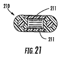
図21は、ケーブル180に類似したケーブル210を示しているが、このケーブル210は、少なくとも1つの外装層211、この実施形態では、2つの外装層211を更に有している。外装層211は、例えば齧歯類(ネズミ類)又は圧潰点接触に起因する意図しない破れを阻止するためにキャビティの上下にそれぞれ位置決めされる。外装層211を任意適当な材料、例えば導電性材料、例えば鋼又は誘電体、例えばポリイミド、ポリカーボネート又はガラス繊維、アラミド等で作られた編組ファブリックで作ることができる。図22は、少なくとも1つの外装層221を有する別のケーブル220を示している。ケーブル220は、ケーブル180に類似しているが、ケーブルジャケット228に巻き付けられた外装層221を有し、更に第2のジャケット228aが施されており、それにより外装層221が被覆されている。
FIG. 21 shows a
図23は、ケーブル180に類似したケーブル230を示しているが、このケーブル230は、光ケーブルを保護するためのチューブ231を更に有している。チューブ231を任意適当な材料で作ることができ、このチューブは、ケーブルの光ファイバを更に保護する。チューブ231を別個の押し出し法で又はケーブルジャケット238との同時押し出し品として形成することができる。ケーブル231をケーブルジャケットと共に任意適当な材料、例えばポリマーで作ることができる。一例を挙げると、一実施形態は、HDPで作られたチューブを有し、ケーブルジャケットは、MDPEで作られるが、材料の適当な組み合わせを用いることができる。同様に、難燃材料を用いても良く、それにより、ケーブルは、屋内用途に適したものになる。さらに、ケーブル230は、埋設用途においてケーブルの存在場所を突き止めるのに有用なトーニング(toning)ワイヤ233を備えたトーニングローブ238aを更に有する。トーニングローブ238aは、ウェブ(符号は付けられていない)によってケーブルジャケット238に連結され、それによりトーニングローブ238aをケーブル本体から分離することができる。さらに、トーニングローブが設けられていないケーブルは、導電性である1つ又は2つ以上のケーブルコンポーネントを用いることによりトーナブルであるという能力を備えるのが良い。さらに、ケーブルは、ケーブルコンポーネント(例えば、銅線の撚り対を含む)のうちの1つ又は2つ以上が導電性である場合、又は、導電性抗張力体を用いて電力を送ることができる。
FIG. 23 shows a
図24及び図25は、それぞれ、ケーブル180に類似したケーブル240,250を示しているが、これらケーブルは、互いに異なる断面ケーブル形状を有している。ケーブル240は、ケーブルジャケット248について全体としてドッグボーン(犬に与える骨の形)のケーブル断面を示し、ケーブル250は、ケーブル断面に関する別の形態を示している。ケーブル250は、凹み部分258aを有し、その結果、技術士がケーブルの一部分に沿って抗張力体259のうちの1本又は2本以上を分離することができるようになっている。当然のことながら、本発明の範囲内で他の断面形状が可能である。
24 and 25
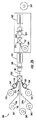
図26は、本発明のケーブル180のための例示の製造ライン260を概略的に示しているが、本発明の技術的思想の他の変形例を用いても本発明の技術的思想に従って他の組立体及び(又は)他のケーブルを製造することができる。製造ライン260は、少なくとも1つの光リボン繰り出しリール261、複数個のドライインサート繰り出しリール262、複数個の抗張力体繰り出しリール263、複数個の抗張力体キャプスタン264、クロスヘッド押出機265、水トラフ266、1つ又は2つ以上のキャタプラー(caterpuller )267及び巻取りリール269を有している。さらに、ケーブル180は、外装層及びこの周りに施された第2のケーブルジャケットを更に有するのが良く、それにより、図22に示すようなケーブル220に類似したケーブルが形成される。外装層及び(又は)第2のケーブルジャケットをケーブル180と同一の製造ライン又は第2の製造ラインで製造することができる。例示の製造法は、少なくとも1本の光ファイバリボン182及びドライインサート184a,184bをそれぞれのリール261,262,262から繰り出すステップを有する。分かりやすくするために、光ファイバリボン182について繰り出しリールが1つだけ示されている。しかしながら、製造ラインは、本発明に従って組立体及び(又は)ケーブルを製造するために1本又は2本以上のリボン又は光ファイバについて任意適当な数の繰り出しリールを有することができる。しかる後、ドライインサート184a,184bを全体として光ファイバリボン182周りに位置決めし、それによりケーブルコア185(即ち、ドライインサートとリボンの複合スタック又はサンドイッチ)を形成する。さらに、抗張力体189をそれぞれの抗張力体キャプスタン264を用いて比較的大きな張力(例えば、約100〜400ポンド(45.36〜181.44kg)の下でそれぞれのリール263から繰り出し、それにより抗張力体189(矢印で示されている)を弾性的に延伸してERLがケーブルに生じるようにする。換言すると、抗張力体189に加わる張力を除いた後、抗張力体は、これらの元の応力を受けていない状態の長さに戻り(即ち、短くなり)、それによりERLを生じさせる。というのは、リボンが、張力を受けた抗張力体とほぼ同じ長さの状態でケーブル内に導入され、リボンは延伸されないからである。換言すると、生じるERLの量は、抗張力体の歪と生じる場合のあるケーブルジャケットの塑性縮みを加えた大体の量に等しい。しかる後、ケーブルコア185及び抗張力体189をクロスヘッド押出機265中に送り込み、ここでケーブルジャケット188をケーブルコア185及び抗張力体189周りに押し出し、それによりケーブル180を形成する。次に、ケーブル180を水トラフ266内で急冷する。1つ又は2つ以上のキャタプラー267を用いてケーブル180を製造ラインから引き出し、次に小さな張力の下で巻取りリール269に巻き付ける。ボックス内に示されているように、1つの製造ラインがケーブル220に類似したケーブルを製造するよう組み立てられている場合、外装層221をリール270から繰り出し、適当な外装形成機器(図示せず)を用いてこの外装層をケーブル180周りに形成するときに第2のキャタプラー267を用いてケーブル組立体を引っ張り、クロスヘッド押出機272を用いて第2のジャケット188aを外装層221上に押し出す。しかる後、外装が施されたケーブル180′は、第2の水トラフ274中に移動し、その後巻取りリール269に巻き取られる。さらに、本発明の技術的思想による他のケーブル及び(又は)製造ラインが可能である。例えば、ケーブル及び(又は)製造ラインは、吸水膨張性テープ、ヤーン等を有しても良いが、1つ又は2つ以上の他の適当なケーブルコンポーネントを用いることが可能である。
FIG. 26 schematically illustrates an
特許請求の範囲に記載された本発明の範囲に属する本発明の多くの改造例及び他の実施形態は、当業者には明らかになろう。例えば、光導波路を種々のリボンスタック又は例えばリボンスタックの段付きプロフィールのような形態(即ち、リボンスタックの断面が、プラス(+)記号の形状をしている)に形成できる。本発明のケーブルは、S−Z撚り形態ではなく、螺旋に撚り合わされた2本の光チューブ組立体を更に有しても良い。さらに、本発明のドライインサートを図示のように互いに積層しても良く、或いは、個々のコンポーネントとして取り付けても良い。したがって、本発明は、本明細書において開示した特定の実施形態には限定されず、特許請求の範囲に記載された本発明の範囲内で改造及び他の実施形態を想到できることは理解されるべきである。特定の用語を本明細書において用いたが、これら用語は、一般的で且つ説明的な意味でのみ用いられており、本発明を限定する目的で用いられているわけではない。本発明をシリカ系光導波路に関して説明したが、本発明の技術的思想は、他の適当な光導波路及び(又は)ケーブル形態に適用できる。 Many modifications and other embodiments of the invention that fall within the scope of the invention as set forth in the claims will be apparent to those skilled in the art. For example, the light guide can be formed in various ribbon stacks or forms such as a stepped profile of the ribbon stack (ie, the cross section of the ribbon stack has the shape of a plus (+) sign). The cable of the present invention may further include two light tube assemblies twisted in a spiral instead of the SZ twist form. Furthermore, the dry inserts of the present invention may be laminated together as shown, or may be attached as individual components. Accordingly, it is to be understood that the invention is not limited to the specific embodiments disclosed herein, and that modifications and other embodiments can be envisaged within the scope of the invention as set forth in the claims. It is. Although specific terms have been used herein, these terms are used in a generic and descriptive sense only and not for the purpose of limiting the invention. Although the present invention has been described with reference to a silica-based optical waveguide, the technical idea of the present invention can be applied to other suitable optical waveguides and / or cable configurations.
Claims (11)
少なくとも1本の光導波路と、
キャビティが設けられたケーブルジャケットであって、前記キャビティが主要表面を有し、前記少なくとも1本の光導波路が前記キャビティ内に少なくとも部分的に収納され、前記キャビティは、略矩形であり、前記少なくとも1本の光導波路は、前記キャビティ内に収納される複数本の光ファイバリボンのうちの1本の光ファイバリボンの一部分である、ケーブルジャケットと、
前記ケーブルジャケットに取付けられ、前記キャビティの互いに反対側に設けられた少なくとも2本の抗張力体と、
第1のドライインサート及び第2のドライインサートを備え、
前記第1のドライインサート及び第2のドライインサートは、前記少なくとも1本の光導波路が前記第1のドライインサートと前記第2のドライインサートとの間に配置され前記少なくとも1本の光導波路を前記ケーブルジャケットに結合するように、前記キャビティ内に収納され、
前記少なくとも1本の光導波路は少なくとも約0.5N/mの標準化された引抜き力を有し、
前記第1のドライインサートは、前記キャビティの前記主要表面と全体として整列した主要表面を有し、
前記第1のドライインサートと前記第2のドライインサートは複数本の光ファイバリボンを撚られていないスタックの状態にサンドイッチし、該スタックは、正のリボン余長を有し、また該リボン余長に対応するように前記ケーブルの中立軸線の回りに全体として波状に起伏したプロフィールを有し、
前記正のリボン余長の値は、前記キャビティの高さをCHとし、前記リボン厚さをtrとし、所望の最小曲げ半径をRとした場合、
50{(CH−tr)/R}
で与えられるパーセント値以下であり、
前記少なくとも1本の光導波路は、約0.2%以上のリボン余長を有する、
ことを特徴とする光ファイバケーブル。 An optical fiber cable,
At least one optical waveguide;
A cable jacket provided with a cavity, wherein the cavity has a major surface, the at least one optical waveguide is at least partially housed in the cavity, the cavity being substantially rectangular, and the at least one One optical waveguide includes a cable jacket, which is a part of one optical fiber ribbon among a plurality of optical fiber ribbons accommodated in the cavity;
At least two strength members attached to the cable jacket and provided on opposite sides of the cavity;
A first dry insert and a second dry insert;
In the first dry insert and the second dry insert, the at least one optical waveguide is disposed between the first dry insert and the second dry insert, and the at least one optical waveguide is disposed in the at least one optical waveguide. Stored in the cavity so as to be coupled to the cable jacket;
The at least one optical waveguide has a standardized pulling force of at least about 0.5 N / m;
The first dry insert has a major surface generally aligned with the major surface of the cavity;
The first dry insert and the second dry insert sandwich a plurality of optical fiber ribbons in an untwisted stack, the stack having a positive ribbon surplus length, and the ribbon surplus length Having a generally undulating profile around the neutral axis of the cable to correspond to
The value of the positive ribbon extra length is as follows: CH is the height of the cavity, TR is the ribbon thickness, and R is the desired minimum bending radius.
50 {(CH− tr ) / R}
Or less percentages given by,
The at least one optical waveguide has a ribbon extra length of about 0.2% or more;
An optical fiber cable characterized by that.
請求項1記載の光ファイバケーブル。 The first dry insert and the second dry insert have a total uncompressed height, and the total uncompressed height is about 40% or more of a cavity height (CH).
The optical fiber cable according to claim 1.
請求項1記載の光ファイバケーブル。 One of the at least two strength members having a strength body dimension (D), wherein the cavity has a cavity height (CH), and the cavity height (CH) is equal to the strength body dimension (D). Larger than)
The optical fiber cable according to claim 1.
請求項1記載の光ファイバケーブル。 The smaller dimension (H) of the fiber optic cable is about 8 millimeters or less, and the larger dimension (W) of the fiber optic cable is about 15 millimeters or less.
The optical fiber cable according to claim 1.
請求項1記載の光ファイバケーブル。 One of the first dry insert or the second dry insert has a compressible layer and a water-swellable layer.
The optical fiber cable according to claim 1.
請求項1記載の光ファイバケーブル。 The first dry insert has a water-swellable layer, and the water-swellable layer faces outward toward the cavity.
The optical fiber cable according to claim 1.
請求項1記載の光ファイバケーブル。 The at least one optical waveguide is in contact with at least a portion of the first dry insert;
The optical fiber cable according to claim 1.
複数本の光ファイバリボンのうちの1本である光ファイバリボンの一部である少なくとも1本の光ファイバを繰り出すステップと、
第1のドライインサートを繰り出すステップと、
第2のドライインサートを繰り出すステップと、
前記少なくとも1本の光ファイバを前記第1のドライインサートと前記第2のドライインサートとの間に位置決めし、それによりケーブルコアを形成するステップであって、前記第1のドライインサートと前記第2のドライインサートは複数本の光ファイバリボンを撚られていないスタックの状態にサンドイッチし、該スタックは、正のリボン余長を有し、また該リボン余長に対応するように前記ケーブルの中立軸線の回りに全体として波状に起伏したプロフィールを有し、前記正のリボン余長の値は、前記キャビティの高さをCHとし、前記リボン厚さをtrとし、所望の最小曲げ半径をRとした場合、
50{(CH−tr)/R}
で与えられるパーセント値以下であるステップと、
前記第1のドライインサート及び第2のドライインサートが前記少なくとも1本の光導波路を前記ケーブルジャケットに結合させるように、ケーブルジャケットを前記ケーブルコア周りにつけるステップと、を備え、
前記少なくとも1本の光ファイバは少なくとも約0.5N/mの標準化された引抜き力を有し、
前記少なくとも1本の光ファイバは、約0.2%以上のリボン余長を有する、
ことを特徴とする方法。 A method of manufacturing a fiber optic cable comprising:
Unwinding at least one optical fiber that is part of an optical fiber ribbon that is one of a plurality of optical fiber ribbons;
Unwinding the first dry insert;
Unwinding the second dry insert;
Positioning the at least one optical fiber between the first dry insert and the second dry insert, thereby forming a cable core, the first dry insert and the second dry fiber; The dry insert sandwiches a plurality of fiber optic ribbons into an untwisted stack, the stack having a positive ribbon surplus length and a neutral axis of the cable to correspond to the ribbon surplus length. The positive ribbon margin length value is CH, the height of the cavity is CH, the ribbon thickness is tr , and the desired minimum bending radius is R. if you did this,
50 {(CH− tr ) / R}
A step that is less than or equal to the percentage value given in
Attaching a cable jacket around the cable core such that the first dry insert and the second dry insert couple the at least one optical waveguide to the cable jacket;
Wherein the at least one optical fiber have a standardized pull-out force of at least about 0.5 N / m,
The at least one optical fiber has a ribbon extra length of about 0.2% or more;
A method characterized by that.
請求項8記載の方法。 The method further comprises the step of providing at least one strength member, wherein the at least one strength member is elastically stretched during a portion of manufacture, whereby tension is applied to the at least one strength member. Providing a ribbon extra length for the fiber optic ribbon in the cable after removal from the body;
The method of claim 8 .
請求項8記載の方法。 The method further comprises the step of unwinding the plurality of optical fiber ribbons.
The method of claim 8 .
請求項8記載の方法。 And further comprising a step of unwinding the outer layer protecting the optical fiber cable.
The method of claim 8 .
Applications Claiming Priority (3)
| Application Number | Priority Date | Filing Date | Title |
|---|---|---|---|
| US11/351,456 US7277615B2 (en) | 2002-12-19 | 2006-02-10 | Fiber optic cable having a dry insert and methods of making the same |
| US11/351,456 | 2006-02-10 | ||
| PCT/US2006/031902 WO2007092046A1 (en) | 2006-02-10 | 2006-08-16 | Fiber optic cable having a dry insert and methods of making the same |
Publications (3)
| Publication Number | Publication Date |
|---|---|
| JP2009526266A JP2009526266A (en) | 2009-07-16 |
| JP2009526266A5 JP2009526266A5 (en) | 2009-10-01 |
| JP5410097B2 true JP5410097B2 (en) | 2014-02-05 |
Family
ID=38345485
Family Applications (1)
| Application Number | Title | Priority Date | Filing Date |
|---|---|---|---|
| JP2008554220A Expired - Fee Related JP5410097B2 (en) | 2006-02-10 | 2006-08-16 | Optical fiber cable having dry insert and method of manufacturing the same |
Country Status (8)
| Country | Link |
|---|---|
| US (1) | US7277615B2 (en) |
| EP (1) | EP1982223B1 (en) |
| JP (1) | JP5410097B2 (en) |
| CN (1) | CN101401018B (en) |
| AU (1) | AU2006337663B2 (en) |
| CA (1) | CA2642016C (en) |
| ES (1) | ES2614633T3 (en) |
| WO (1) | WO2007092046A1 (en) |
Families Citing this family (56)
| Publication number | Priority date | Publication date | Assignee | Title |
|---|---|---|---|---|
| US7336873B2 (en) | 2002-12-19 | 2008-02-26 | Corning Cable Systems, Llc. | Optical tube assembly having a dry insert and methods of making the same |
| US7415181B2 (en) * | 2005-07-29 | 2008-08-19 | Corning Cable Systems Llc | Fiber optic cables and assemblies for fiber to the subscriber applications |
| US6970629B2 (en) | 2002-12-19 | 2005-11-29 | Corning Cable Systems Llc | Optical tube assembly having a dry insert and methods of making the same |
| US7471862B2 (en) | 2002-12-19 | 2008-12-30 | Corning Cable Systems, Llc | Dry fiber optic cables and assemblies |
| US7567739B2 (en) * | 2007-01-31 | 2009-07-28 | Draka Comteq B.V. | Fiber optic cable having a water-swellable element |
| US7515795B2 (en) * | 2005-07-20 | 2009-04-07 | Draka Comteq B.V. | Water-swellable tape, adhesive-backed for coupling when used inside a buffer tube |
| US7599589B2 (en) * | 2005-07-20 | 2009-10-06 | Draka Comteq B.V. | Gel-free buffer tube with adhesively coupled optical element |
| US7391944B2 (en) * | 2005-08-25 | 2008-06-24 | Draka Comteq B.V. | Fiber optic cable with a concave surface |
| US7272289B2 (en) * | 2005-09-30 | 2007-09-18 | Corning Incorporated | Low bend loss optical fiber |
| US8582938B2 (en) | 2006-05-11 | 2013-11-12 | Corning Cable Systems Llc | Fiber optic distribution cables and structures therefore |
| US7664354B2 (en) * | 2006-08-01 | 2010-02-16 | Nexans | System and method for loose tube tight buffer indoor/outdoor optical fiber cable |
| US7406232B2 (en) * | 2006-08-31 | 2008-07-29 | Corning Cable Systems Llc | Non-round fiber optic cable having improved major axis crush resistance |
| US7406233B2 (en) | 2006-11-22 | 2008-07-29 | Corning Cable Systems Llc | Fiber optic cable having a dry insert with a fold |
| US7536073B2 (en) | 2006-11-22 | 2009-05-19 | Corning Cable Systems Llc | Fiber optic cable having a dry insert and offset cavity |
| US7463812B2 (en) * | 2007-01-19 | 2008-12-09 | Adc Telecommunications, Inc. | Overhead cable termination arrangement |
| US20080205830A1 (en) * | 2007-02-23 | 2008-08-28 | Superior Essex Communications Lp | Method and apparatus for protecting optical fibers of a cable |
| US20090034918A1 (en) * | 2007-07-31 | 2009-02-05 | William Eric Caldwell | Fiber optic cables having coupling and methods therefor |
| US7529451B2 (en) * | 2007-07-31 | 2009-05-05 | Corning Cable Systems Llc | Fiber optic cables using dry inserts for coupling and methods therefor |
| US7567741B2 (en) * | 2007-11-26 | 2009-07-28 | Corning Cable Systems Llc | Fiber optic cables and assemblies for fiber toward the subscriber applications |
| US7539380B1 (en) * | 2007-11-26 | 2009-05-26 | Corning Cable Systems Llc | Fiber optic cables and assemblies for fiber toward the subscriber applications |
| EP2294467A4 (en) * | 2008-05-27 | 2015-02-25 | Adc Telecommunications Inc | Multi-jacketed fiber optic cable |
| US7916989B2 (en) | 2008-07-31 | 2011-03-29 | Corning Cable Systems Llc | Optical fiber assemblies having a powder or powder blend at least partially mechanically attached |
| ES2640011T3 (en) | 2008-08-15 | 2017-10-31 | Corning Optical Communications LLC | Fiber optic assembly and manufacturing methods |
| PT2338076E (en) | 2008-09-23 | 2013-09-06 | Corning Cable Sys Llc | Fibre optic cable |
| US7729584B2 (en) * | 2008-10-01 | 2010-06-01 | Corning Cable Systems Llc | Method of providing mid-span access to an optical fiber ribbon cable and the optical fiber ribbon cable |
| US20100109174A1 (en) | 2008-11-05 | 2010-05-06 | George Cornelius Abernathy | Method for drop cable having an oval cavity |
| WO2010065632A1 (en) | 2008-12-02 | 2010-06-10 | Corning Cable Systems Llc | Optical fiber array cables and associated fiber optic cables and systems |
| ES2735999T3 (en) | 2008-12-09 | 2019-12-23 | Prysmian Spa | Optical cable with dry core and dry protection tubes |
| ES2573329T3 (en) | 2008-12-30 | 2016-06-07 | Draka Comteq B.V. | Fiber optic cable comprising a perforated water blocking element |
| US9842670B2 (en) | 2013-11-08 | 2017-12-12 | Rockbestos Surprenant Cable Corp. | Cable having polymer with additive for increased linear pullout resistance |
| US8625945B1 (en) * | 2009-05-13 | 2014-01-07 | Draka Comteq, B.V. | Low-shrink reduced-diameter dry buffer tubes |
| US8625944B1 (en) * | 2009-05-13 | 2014-01-07 | Draka Comteq, B.V. | Low-shrink reduced-diameter buffer tubes |
| WO2011008194A1 (en) | 2009-07-13 | 2011-01-20 | Ben Wells | Optical fiber cable having dummy rods with non-circular cross-section |
| US9042693B2 (en) * | 2010-01-20 | 2015-05-26 | Draka Comteq, B.V. | Water-soluble water-blocking element |
| US20110262089A1 (en) * | 2010-04-23 | 2011-10-27 | Kuang-Bang Hsu | Small-diameter high bending-resistance fiber optic cable |
| US8682123B2 (en) | 2010-07-15 | 2014-03-25 | Draka Comteq, B.V. | Adhesively coupled optical fibers and enclosing tape |
| US9120693B2 (en) | 2010-11-08 | 2015-09-01 | Corning Incorporated | Multi-core optical fiber ribbons and methods for making the same |
| AU2012285834B2 (en) * | 2011-07-21 | 2016-02-25 | Commscope Technologies Llc | Method for extruding a drop cable |
| US8682124B2 (en) | 2011-10-13 | 2014-03-25 | Corning Cable Systems Llc | Access features of armored flat fiber optic cable |
| ES2703235T3 (en) * | 2011-11-23 | 2019-03-07 | Adc Telecommunications Inc | Fiber optic multi-fiber connector |
| US9052459B2 (en) | 2012-03-23 | 2015-06-09 | Corning Cable Systems Llc | Cable assembly and method |
| US9557505B2 (en) | 2013-03-18 | 2017-01-31 | Commscope Technologies Llc | Power and optical fiber interface |
| WO2014197103A2 (en) | 2013-03-18 | 2014-12-11 | Adc Telecommunications, Inc. | Architecture for a wireless network |
| MX359326B (en) | 2013-05-14 | 2018-09-25 | Adc Telecommunications Inc | Power/fiber hybrid cable. |
| US9415551B2 (en) | 2013-06-13 | 2016-08-16 | Corning Cable Systems Llc | Coupling system for a fiber optic cable |
| US8805144B1 (en) | 2013-09-24 | 2014-08-12 | Corning Optical Communications LLC | Stretchable fiber optic cable |
| US9075212B2 (en) | 2013-09-24 | 2015-07-07 | Corning Optical Communications LLC | Stretchable fiber optic cable |
| BR212016015377U2 (en) * | 2013-12-30 | 2016-09-27 | Corning Optical Comm Llc | binder film system |
| CN104181656B (en) * | 2014-08-29 | 2016-03-16 | 长飞光纤光缆股份有限公司 | A kind of dry type all dielectric optical fibre band optical cable and preparation method thereof |
| EP3539255A4 (en) | 2016-11-09 | 2020-05-27 | Commscope Inc. of North Carolina | Exchangeable powered infrastructure module |
| US11029477B2 (en) * | 2017-03-21 | 2021-06-08 | Sumitomo Electric Industries, Ltd. | Optical fiber cable |
| US11125959B2 (en) * | 2018-12-06 | 2021-09-21 | Sterlite Technologies Limited | Flat drop optical fiber cable |
| US11327203B1 (en) | 2020-04-22 | 2022-05-10 | Superior Essex International LP | Optical fiber cables substantially free of colorant |
| US20210333497A1 (en) * | 2020-04-22 | 2021-10-28 | Superior Essex International LP | Optical fiber cables substantially free of colorant |
| JP2021182040A (en) * | 2020-05-18 | 2021-11-25 | 住友電気工業株式会社 | Manufacturing method for fan-in fan-out device, and fan-in fan-out device |
| US11846822B2 (en) * | 2021-12-29 | 2023-12-19 | Sterlite Technologies Limited | Optical fiber cable with compressed core and manufacturing method thereof |
Family Cites Families (88)
| Publication number | Priority date | Publication date | Assignee | Title |
|---|---|---|---|---|
| US4078853A (en) * | 1976-02-25 | 1978-03-14 | Bell Telephone Laboratories, Incorporated | Optical communication cable |
| US4226504A (en) | 1976-03-15 | 1980-10-07 | Akzona Incorporated | Protection of optical fibers |
| DE2743260C2 (en) | 1977-09-26 | 1990-05-31 | kabelmetal electro GmbH, 3000 Hannover | Optical fiber communications cable and process for its manufacture |
| US4420220A (en) | 1979-06-25 | 1983-12-13 | Bicc Public Limited Company | Optical guides |
| FR2460491A1 (en) | 1979-07-02 | 1981-01-23 | Radiall Sa | IMPROVEMENTS ON OPTICAL CABLES |
| DE2944997C2 (en) | 1979-11-08 | 1981-03-26 | Kabel Rheydt AG, 41238 Mönchengladbach | Light guide arrangement |
| US4446686A (en) | 1982-09-02 | 1984-05-08 | At&T Technologies, Inc. | Methods of and apparatus for controlling core-to-sheath length ratio in lightguide fiber cable and cable produced by the methods |
| JPS6087307A (en) | 1983-10-20 | 1985-05-17 | Nippon Telegr & Teleph Corp <Ntt> | Flat optical cable |
| JPS60205408A (en) | 1984-03-29 | 1985-10-17 | Sumitomo Electric Ind Ltd | Waterproof type communication cable and its production |
| GB8413205D0 (en) | 1984-05-23 | 1984-06-27 | Telephone Cables Ltd | Optical fibre cables |
| DE3444500A1 (en) | 1984-05-24 | 1985-11-28 | kabelmetal electro GmbH, 3000 Hannover | Flame-resistant electrical or optical cable |
| JPS6123104A (en) | 1984-07-12 | 1986-01-31 | Sumitomo Electric Ind Ltd | High density storage type optical fiber cable |
| JPS61167602U (en) * | 1985-04-09 | 1986-10-17 | ||
| US4707569A (en) | 1985-06-03 | 1987-11-17 | Japan Styrene Paper Corporation | Multi-conductor cable |
| ATE56826T1 (en) | 1985-07-05 | 1990-10-15 | Siemens Ag | FILLING COMPOUND FOR FIBER OPTIC WIRE AND/OR FIBER OPTIC CABLE. |
| GB8608864D0 (en) | 1986-04-11 | 1986-05-14 | Ass Elect Ind | Optical/electrical/composite cable |
| US4725629A (en) | 1986-07-18 | 1988-02-16 | Kimberly-Clark Corporation | Process of making an interpenetrating superabsorbent polyurethane foam |
| US4725628A (en) | 1986-07-18 | 1988-02-16 | Kimberly-Clark Corporation | Process of making a crosslinked superabsorbent polyurethane foam |
| US4818060A (en) | 1987-03-31 | 1989-04-04 | American Telephone And Telegraph Company, At&T Bell Laboratories | Optical fiber building cables |
| JP2506111B2 (en) * | 1987-05-21 | 1996-06-12 | 日本電信電話株式会社 | Optical fiber cable manufacturing method |
| US4815813A (en) | 1987-10-30 | 1989-03-28 | American Telephone And Telegraph Company | Water resistant communications cable |
| US4913517A (en) | 1988-07-11 | 1990-04-03 | American Telephone And Telegraph Company, At&T Bell Laboratories | Communication cable having water blocking strength members |
| US4909592A (en) | 1988-09-29 | 1990-03-20 | American Telephone And Telegraph Company, At&T Bell Laboratories | Communication cable having water blocking provisions in core |
| DE3843778A1 (en) | 1988-12-24 | 1990-07-05 | Philips Patentverwaltung | METHOD FOR PRODUCING AN OPTICAL LINE |
| US4979795A (en) * | 1989-06-29 | 1990-12-25 | At&T Bell Laboratories | Coilable torque-balanced cable and method of manufacture |
| US5016952A (en) | 1989-12-22 | 1991-05-21 | At&T Bell Laboratories | Cable closure including superabsorbent foam water blocking system and methods of using same |
| JP2775966B2 (en) | 1990-03-15 | 1998-07-16 | 住友電気工業株式会社 | Optical fiber unit |
| US5125063A (en) * | 1990-11-08 | 1992-06-23 | At&T Bell Laboratories | Lightweight optical fiber cable |
| US5133034A (en) | 1991-08-20 | 1992-07-21 | At&T Bell Laboratories | Communications cable having a strength member system disposed between two layers of waterblocking material |
| US5224190A (en) | 1992-03-31 | 1993-06-29 | At&T Bell Laboratories | Underwater optical fiber cable having optical fiber coupled to grooved metallic core member |
| US5243675A (en) | 1992-04-16 | 1993-09-07 | At&T Bell Laboratories | Optical fiber cable which resists damage caused by a hostile environment |
| DE9208880U1 (en) | 1992-07-01 | 1992-11-19 | Siemens Ag, 8000 Muenchen, De | |
| JPH06309951A (en) | 1993-04-23 | 1994-11-04 | Sumitomo Electric Ind Ltd | Optical fiber composite overhead ground-wire and its manufacture |
| JPH07159629A (en) * | 1993-12-03 | 1995-06-23 | Fujikura Ltd | Coated optical fiber tape unit and optical cable |
| US5422973A (en) | 1994-03-28 | 1995-06-06 | Siecor Corporation | Water blocked unfilled single tube cable |
| US5509097A (en) | 1994-04-07 | 1996-04-16 | Pirelli Cable Corporation | Optical fiber core and cable with reinforced buffer tube loosely enclosing optical fibers |
| DE4418319C3 (en) | 1994-05-26 | 2001-08-09 | Stockhausen Chem Fab Gmbh | Layered body for the absorption of liquids and its manufacture and use |
| FR2725042B1 (en) | 1994-09-26 | 1996-12-27 | Alcatel Cable | OPTICAL FIBER CABLE AND DEVICE FOR MANUFACTURING SUCH A CABLE |
| DE19516970A1 (en) | 1995-05-09 | 1996-11-14 | Siemens Ag | Electric and optical cable filler with max. swelling power if water enters |
| US5689601A (en) | 1995-08-24 | 1997-11-18 | Owens-Corning Fiberglas Technology Inc. | Water blocking optical cable reinforcement |
| US5621841A (en) | 1995-09-20 | 1997-04-15 | Siecor Corporation | Optical fiber cable containing ribbons in stranded tubes |
| US5630003A (en) * | 1995-11-30 | 1997-05-13 | Lucent Technologies Inc. | Loose tube fiber optic cable |
| JPH09152535A (en) | 1995-11-30 | 1997-06-10 | Showa Electric Wire & Cable Co Ltd | Water-stopping tape and optical fiber cable using the same |
| US5668912A (en) * | 1996-02-07 | 1997-09-16 | Alcatel Na Cable Systems, Inc. | Rectangular optical fiber cable |
| JP3583221B2 (en) | 1996-02-15 | 2004-11-04 | 三洋化成工業株式会社 | Filling material for cable |
| US5684904A (en) | 1996-06-10 | 1997-11-04 | Siecor Corporation | Optical cable incorporating loose buffer tubes coated with a moisture-absorptive material |
| FR2756935B1 (en) | 1996-12-09 | 1999-01-08 | Alsthom Cge Alcatel | REINFORCED FIBER CABLE, WITH UNITUBE STRUCTURE |
| US6229944B1 (en) | 1997-02-04 | 2001-05-08 | Sumitomo Electric Industries, Ltd. | Optical fiber cable |
| DE19713063A1 (en) | 1997-03-27 | 1998-10-01 | Siemens Ag | Communications cable device for e.g. optical fibre ribbon |
| US6122424A (en) | 1997-09-26 | 2000-09-19 | Siecor Corporation | Fiber optic cable with flame inhibiting capability |
| US6178278B1 (en) | 1997-11-13 | 2001-01-23 | Alcatel | Indoor/outdoor dry optical fiber cable |
| US6087000A (en) | 1997-12-18 | 2000-07-11 | Ppg Industries Ohio, Inc. | Coated fiber strands, composites and cables including the same and related methods |
| JPH11271581A (en) | 1998-03-25 | 1999-10-08 | Fujikura Ltd | Optical fiber and its manufacture |
| US6574400B1 (en) | 1998-03-26 | 2003-06-03 | Corning Cable Systems Llc | Fiber optic cable with water blocking features |
| JPH11337783A (en) | 1998-05-27 | 1999-12-10 | Fujikura Ltd | Optical cable |
| US6586094B1 (en) | 1998-11-24 | 2003-07-01 | E. I. Du Pont De Nemours And Company | Fiber coated with water blocking material |
| US6377738B1 (en) * | 1998-12-04 | 2002-04-23 | Pirelli Cable Corporation | Optical fiber cable and core with a reinforced buffer tube having visible strength members and methods of manufacture thereof |
| US6748146B2 (en) | 1999-05-28 | 2004-06-08 | Corning Cable Systems Llc | Communication cable having a soft housing |
| US6463199B1 (en) | 1999-05-28 | 2002-10-08 | Corning Cable Systems Llc | Fiber optic cables with at least one water blocking zone |
| US6314224B1 (en) * | 1999-06-18 | 2001-11-06 | Alcatel | Thick-walled cable jacket with non-circular cavity cross section |
| US6226431B1 (en) | 1999-06-29 | 2001-05-01 | Lucent Technology Inc. | Optical fiber cable |
| US6321012B1 (en) | 1999-08-30 | 2001-11-20 | Alcatel | Optical fiber having water swellable material for identifying grouping of fiber groups |
| US6278826B1 (en) | 1999-09-15 | 2001-08-21 | Lucent Technologies Inc. | Cables with water-blocking and flame-retarding foam |
| US6728451B2 (en) * | 1999-09-21 | 2004-04-27 | Tyco Telecommunications (Us) Inc. | Optical fiber holding structure and method of making same |
| JP2001343566A (en) | 2000-05-31 | 2001-12-14 | Fujikura Ltd | Optical cable |
| JP2001343565A (en) | 2000-05-31 | 2001-12-14 | Fujikura Ltd | Optical cable |
| EP1170614A1 (en) | 2000-06-07 | 2002-01-09 | Lucent Technologies Inc. | Dry-blocked armored cable having reduced water penetration |
| WO2002057828A2 (en) | 2001-01-16 | 2002-07-25 | Parker Hannifin Corporation | Flame retardant tubing for a bundle |
| JP4458689B2 (en) * | 2001-02-06 | 2010-04-28 | 株式会社フジクラ | Fiber optic cable |
| JP2002236241A (en) | 2001-02-08 | 2002-08-23 | Fujikura Ltd | Optical cable |
| TW531676B (en) * | 2001-03-29 | 2003-05-11 | Fujikura Ltd | Optical fiber cable, apparatus and method for manufacturing the same |
| US6714708B2 (en) * | 2001-03-30 | 2004-03-30 | Corning Cable Systems Llc | Fiber optic with high strength component |
| US6389204B1 (en) | 2001-05-30 | 2002-05-14 | Corning Cable Systems Llc | Fiber optic cables with strength members and methods of making the same |
| US7302143B2 (en) | 2001-06-04 | 2007-11-27 | Pirelli & C. S.P.A. | Optical cable provide with a mechanically resistant covering |
| DE10129772B4 (en) * | 2001-06-20 | 2007-10-11 | CCS Technology, Inc., Wilmington | Optical transmission element |
| US6504979B1 (en) | 2001-09-06 | 2003-01-07 | Fitel Usa Corp. | Water blocking optical fiber cable |
| MXPA01009019A (en) | 2001-09-06 | 2003-03-10 | Servicios Condumex Sa | Dry optical fiber cable for telecommunications. |
| US6618526B2 (en) * | 2001-09-27 | 2003-09-09 | Corning Cable Systems Llc | Fiber optic cables |
| US6749446B2 (en) | 2001-10-10 | 2004-06-15 | Alcatel | Optical fiber cable with cushion members protecting optical fiber ribbon stack |
| JP3596511B2 (en) | 2001-10-18 | 2004-12-02 | 住友電気工業株式会社 | Fiber optic cable |
| US6847768B2 (en) * | 2002-09-06 | 2005-01-25 | Corning Cable Systems Llc | Optical fiber tube assembly having a plug |
| JP2004139068A (en) * | 2002-09-26 | 2004-05-13 | Fujikura Ltd | Optical fiber cable and its structure |
| JP2004151434A (en) * | 2002-10-31 | 2004-05-27 | Fujikura Ltd | Optical drop cable |
| AU2003274752A1 (en) * | 2002-10-25 | 2004-05-13 | Fujikura Ltd. | Optical drop cable |
| US7254302B2 (en) * | 2002-12-19 | 2007-08-07 | Corning Cable Systems, Llc. | Optical tube assembly having a dry insert and methods of making the same |
| US7177507B2 (en) * | 2002-12-19 | 2007-02-13 | Corning Cable Systems, Llc | Optical tube assembly having a dry insert and methods of making the same |
| US6934452B2 (en) * | 2003-04-22 | 2005-08-23 | Furukawa Electric North America Inc. | Optical fiber cables |
| US6931184B2 (en) * | 2003-05-30 | 2005-08-16 | Corning Cable Systems Llc | Dry tube fiber optic assemblies, cables, and manufacturing methods therefor |
-
2006
- 2006-02-10 US US11/351,456 patent/US7277615B2/en not_active Expired - Lifetime
- 2006-08-16 CA CA2642016A patent/CA2642016C/en not_active Expired - Fee Related
- 2006-08-16 CN CN2006800537551A patent/CN101401018B/en not_active Expired - Fee Related
- 2006-08-16 EP EP06789785.0A patent/EP1982223B1/en not_active Not-in-force
- 2006-08-16 ES ES06789785.0T patent/ES2614633T3/en active Active
- 2006-08-16 AU AU2006337663A patent/AU2006337663B2/en not_active Ceased
- 2006-08-16 JP JP2008554220A patent/JP5410097B2/en not_active Expired - Fee Related
- 2006-08-16 WO PCT/US2006/031902 patent/WO2007092046A1/en active Application Filing
Also Published As
| Publication number | Publication date |
|---|---|
| CA2642016A1 (en) | 2007-08-16 |
| AU2006337663A2 (en) | 2008-10-30 |
| EP1982223A1 (en) | 2008-10-22 |
| CN101401018A (en) | 2009-04-01 |
| AU2006337663B2 (en) | 2012-08-30 |
| CA2642016C (en) | 2015-10-13 |
| US7277615B2 (en) | 2007-10-02 |
| US20060165355A1 (en) | 2006-07-27 |
| CN101401018B (en) | 2011-11-16 |
| EP1982223A4 (en) | 2012-08-29 |
| AU2006337663A1 (en) | 2007-08-16 |
| ES2614633T3 (en) | 2017-06-01 |
| WO2007092046A1 (en) | 2007-08-16 |
| EP1982223B1 (en) | 2016-11-09 |
| JP2009526266A (en) | 2009-07-16 |
Similar Documents
| Publication | Publication Date | Title |
|---|---|---|
| JP5410097B2 (en) | Optical fiber cable having dry insert and method of manufacturing the same | |
| AU2007325773B2 (en) | Fiber optic cable having a dry insert and methods of making the same | |
| JP4948408B2 (en) | Light tube assembly with dry insert | |
| CN100456071C (en) | Optical tube assembly having a dry insert and methods of making the same | |
| US7747117B2 (en) | Optical tube assembly having a dry insert and methods of making the same | |
| US7254303B2 (en) | Optical tube assembly having a dry insert and methods of making the same | |
| US20040240808A1 (en) | Dry fiber optic assemblies and cables |
Legal Events
| Date | Code | Title | Description |
|---|---|---|---|
| A521 | Request for written amendment filed |
Free format text: JAPANESE INTERMEDIATE CODE: A523 Effective date: 20090812 |
|
| A621 | Written request for application examination |
Free format text: JAPANESE INTERMEDIATE CODE: A621 Effective date: 20090812 |
|
| A977 | Report on retrieval |
Free format text: JAPANESE INTERMEDIATE CODE: A971007 Effective date: 20120201 |
|
| A131 | Notification of reasons for refusal |
Free format text: JAPANESE INTERMEDIATE CODE: A131 Effective date: 20120206 |
|
| A601 | Written request for extension of time |
Free format text: JAPANESE INTERMEDIATE CODE: A601 Effective date: 20120424 |
|
| A602 | Written permission of extension of time |
Free format text: JAPANESE INTERMEDIATE CODE: A602 Effective date: 20120502 |
|
| A521 | Request for written amendment filed |
Free format text: JAPANESE INTERMEDIATE CODE: A523 Effective date: 20120806 |
|
| A131 | Notification of reasons for refusal |
Free format text: JAPANESE INTERMEDIATE CODE: A131 Effective date: 20120903 |
|
| A601 | Written request for extension of time |
Free format text: JAPANESE INTERMEDIATE CODE: A601 Effective date: 20121130 |
|
| A602 | Written permission of extension of time |
Free format text: JAPANESE INTERMEDIATE CODE: A602 Effective date: 20121207 |
|
| A521 | Request for written amendment filed |
Free format text: JAPANESE INTERMEDIATE CODE: A523 Effective date: 20130304 |
|
| A131 | Notification of reasons for refusal |
Free format text: JAPANESE INTERMEDIATE CODE: A131 Effective date: 20130325 |
|
| A601 | Written request for extension of time |
Free format text: JAPANESE INTERMEDIATE CODE: A601 Effective date: 20130619 |
|
| A602 | Written permission of extension of time |
Free format text: JAPANESE INTERMEDIATE CODE: A602 Effective date: 20130626 |
|
| A601 | Written request for extension of time |
Free format text: JAPANESE INTERMEDIATE CODE: A601 Effective date: 20130823 |
|
| A602 | Written permission of extension of time |
Free format text: JAPANESE INTERMEDIATE CODE: A602 Effective date: 20130830 |
|
| A521 | Request for written amendment filed |
Free format text: JAPANESE INTERMEDIATE CODE: A523 Effective date: 20130925 |
|
| TRDD | Decision of grant or rejection written | ||
| A01 | Written decision to grant a patent or to grant a registration (utility model) |
Free format text: JAPANESE INTERMEDIATE CODE: A01 Effective date: 20131015 |
|
| A61 | First payment of annual fees (during grant procedure) |
Free format text: JAPANESE INTERMEDIATE CODE: A61 Effective date: 20131106 |
|
| R150 | Certificate of patent or registration of utility model |
Ref document number: 5410097 Country of ref document: JP Free format text: JAPANESE INTERMEDIATE CODE: R150 |
|
| R250 | Receipt of annual fees |
Free format text: JAPANESE INTERMEDIATE CODE: R250 |
|
| R250 | Receipt of annual fees |
Free format text: JAPANESE INTERMEDIATE CODE: R250 |
|
| R250 | Receipt of annual fees |
Free format text: JAPANESE INTERMEDIATE CODE: R250 |
|
| R250 | Receipt of annual fees |
Free format text: JAPANESE INTERMEDIATE CODE: R250 |
|
| LAPS | Cancellation because of no payment of annual fees |