JP5409418B2 - Electronics - Google Patents
Electronics Download PDFInfo
- Publication number
- JP5409418B2 JP5409418B2 JP2010021166A JP2010021166A JP5409418B2 JP 5409418 B2 JP5409418 B2 JP 5409418B2 JP 2010021166 A JP2010021166 A JP 2010021166A JP 2010021166 A JP2010021166 A JP 2010021166A JP 5409418 B2 JP5409418 B2 JP 5409418B2
- Authority
- JP
- Japan
- Prior art keywords
- speaker
- microphone
- signal line
- microphones
- holding
- Prior art date
- Legal status (The legal status is an assumption and is not a legal conclusion. Google has not performed a legal analysis and makes no representation as to the accuracy of the status listed.)
- Active
Links
Images


Description
本発明は、スピーカとマイクを備える例えばデジタルカメラや携帯電話機等の電子機器に関する。 The present invention relates to an electronic device including a speaker and a microphone, such as a digital camera or a mobile phone.
従来、マイクとスピーカとを一つの保持部材に組み付け、組み付けたマイクとスピーカを弾性的に保持して外れにくくすることにより組付効率を高めた技術が提案されている(特許文献1)。また、マイクの出力信号は、他の信号線等からのノイズを受けやすいため、差動アンプを用いてノイズを受けにくくした技術が提案されている(特許文献2)。 Conventionally, a technique has been proposed in which a microphone and a speaker are assembled to one holding member, and the assembled microphone and speaker are elastically held to make it difficult to come off (Patent Document 1). Further, since the output signal of the microphone is susceptible to noise from other signal lines or the like, a technique has been proposed in which it is difficult to receive noise using a differential amplifier (Patent Document 2).
上記特許文献1では、マイク出力信号へのノイズの重畳を抑える対策については、開示されていない。スピーカとマイクとの配線は、ケーブルやフレキシブルプリント基板を用いて行われるが、ケーブルを用いた場合は、スピーカや外部からのノイズがマイク出力信号に重畳されやすい。また、フレキシブルプリント基板を用いる場合には、両面フレキシブルプリント基板の一方の面にマイクの出力信号線を配置し、他方の面にグランド(GND)パターンを配置して、マイク出力信号へのノイズの重畳を抑える必要があり、コスト高になる。 The above-mentioned Patent Document 1 does not disclose a measure for suppressing noise superposition on the microphone output signal. Wiring between the speaker and the microphone is performed using a cable or a flexible printed board, but when the cable is used, noise from the speaker or the outside is easily superimposed on the microphone output signal. When a flexible printed circuit board is used, a microphone output signal line is disposed on one surface of the double-sided flexible printed circuit board, and a ground (GND) pattern is disposed on the other surface, so that noise to the microphone output signal can be reduced. It is necessary to suppress superposition, and the cost increases.
一方、上記特許文献2では、差動アンプを用いることで、マイク出力信号へのノイズの重畳を抑えることができるが、差動回路が必要になるため、コスト高になる。 On the other hand, in Patent Document 2, by using a differential amplifier, it is possible to suppress noise from being superimposed on the microphone output signal. However, since a differential circuit is required, the cost increases.
そこで、本発明は、スピーカとマイクの保持部材への組付効率を向上させることができるとともに、低コストでマイク出力信号へのノイズの重畳を抑えることができる電子機器を提供することを目的とする。 Accordingly, an object of the present invention is to provide an electronic device that can improve the assembly efficiency of the speaker and the microphone to the holding member and can suppress the superposition of noise on the microphone output signal at low cost. To do.
上記目的を達成するために、本発明の電子機器は、スピーカ及びマイクが実装される片面フレキシブル配線基板と、前記スピーカを保持するスピーカ保持部及び前記マイクを保持するマイク保持部を有する保持部材と、を備え、前記保持部材は、前記片面フレキシブル配線基板が折り返された状態で、前記スピーカ及び前記マイクのそれぞれを前記スピーカ保持部及び前記マイク保持部により保持し、前記片面フレキシブル配線基板の前記マイク用の出力信号線は、前記スピーカ用の信号線に隣接して配置され、前記出力信号線と前記信号線との間に前記マイク用のグランド信号線が配置されることを特徴とする。 In order to achieve the above object, an electronic device of the present invention includes a single-sided flexible wiring board on which a speaker and a microphone are mounted, a speaker holding unit that holds the speaker, and a holding member that has a microphone holding unit that holds the microphone. , wherein the retaining member is in a state where the single-sided flexible wiring board is folded, each of the speaker and the microphone is more retained in the speaker holding portion and the microphone holder, of the single-sided flexible wiring board the output signal line for the microphone is disposed adjacent to the signal line for the speaker, and characterized in that the previous SL ground signal line microphone is disposed between the signal line and the output signal line To do.
本発明によれば、スピーカとマイクの保持部材への組付効率を向上させることができるとともに、低コストでマイク出力信号へのノイズの重畳を抑えることができる。 ADVANTAGE OF THE INVENTION According to this invention, while being able to improve the assembly | attachment efficiency to the holding member of a speaker and a microphone, the superimposition of the noise to a microphone output signal can be suppressed at low cost.
以下、本発明の実施形態を図面を参照して説明する。 Hereinafter, embodiments of the present invention will be described with reference to the drawings.
(第1の実施形態)
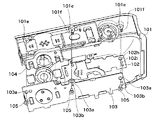
図1は本発明の電子機器の第1の実施形態であるデジタルカメラの要部の分解斜視図、図2は図1を下方から見た分解斜視図である。
(First embodiment)
FIG. 1 is an exploded perspective view of essential parts of a digital camera which is a first embodiment of an electronic apparatus according to the present invention, and FIG. 2 is an exploded perspective view of FIG. 1 viewed from below.
本実施形態のデジタルカメラは、図1に示すように、フロントカバー101の上面部に、スピーカ102aから出力された音を外部に放出するための穴101aが形成されている。フロントカバー101の穴101aの図の左右両側には、左音声入力用マイク102bL及び右音声入力用マイク102bRが外部から入力される音を集音するための穴101bL,101bRが形成されている。マイク102bL,102bRは、例えばシリコンマイク等で構成される。
As shown in FIG. 1, the digital camera according to the present embodiment has a
また、フロントカバー101の上面部には、レリーズスイッチ102cを操作するための不図示のレリーズボタン用の溝101c、電源スイッチ102eを操作するための不図示の電源ボタン用の穴101dが形成されている。更に、フロントカバー101の上面部には、ズームスイッチ102dを操作するための不図示のズームレバー用の穴101eが形成されている。
A
スピーカ102a、左右の音声入力用マイク102bL,102bR、レリーズスイッチ102c、ズームスイッチ102d、電源スイッチ102eは、フレキシブルプリント基板(以下「FPC」という。)102に実装される。FPC102は、後述するメイン配線基板106に電気的に接続される。また、FPC102に実装されたスピーカ102a及びマイク102bL,102bRは、ゴム等の弾性体で形成された保持部材104によって保持される。
The
FPC102の下面側には、固定板103が配置されており、固定板103は、両面テープ等によりFPC102に固定される。固定板103には、ピン状の加締め部103cが形成されており、この加締め部103cをFPC102に形成された位置決め用の穴102fに挿通して加締めることにより、固定板103がFPC102に対して位置決めされる。
A
また、固定板103には、位置決め用の穴103bが形成され、FPC102の穴103bに対応する位置にも、位置決め用の穴102iが形成されている。これらの穴103b,102iをフロントカバー101の突起101f(図2)に嵌め込むことで、固定板103及びFPC102がフロントカバー101に対して位置決めされる。そして、固定板103に形成された複数のビス穴103a及びビス穴103aに対応してFPC102に形成された複数のビス穴102hにビス105を挿入してフロントカバー101に締結する。これにより、FPC102が固定板103とともにフロントカバー101に固定される。
Further, a
次に、図3〜図5を参照して、FPC102に実装されたスピーカ102a及びマイク102bL,102bRを保持部材104に組み付ける方法について説明する。
Next, a method of assembling the
図3はFPC102に実装されたスピーカ102a及びマイク102bL,102bRを保持部材104に組み付ける前の状態を示す斜視図、図4は図3の下方から見た斜視図である。
3 is a perspective view showing a state before the
保持部材104には、中央部にスピーカ102aが嵌め込まれる開口104aが形成され、左右両側にマイク102bL,102bRがそれぞれ嵌め込まれる開口104bが形成されている。開口104aは本発明のスピーカ保持部の一例に相当し、開口104bは本発明のマイク保持部の一例に相当する。保持部材104の下方から開口104a及び左右の開口104bにそれぞれスピーカ102a及びマイク102bL,102bRを押し込んで嵌め込むことで、保持部材104にスピーカ102a及びマイク102bL,102bRが組み付けられる。
In the
図5は、FPC102に実装されたスピーカ102a及びマイク102bL,102bRを保持部材104に組み付けた後の状態を示す斜視図である。
FIG. 5 is a perspective view showing a state after the
図5に示すように、スピーカ102aのフロントカバー101の上面部を向く側の周囲には、該上面部側に突出する弾性筒体102jが貼り付けられている。また、保持部材104のマイク102bL、102bRの音声出力面の周囲には、略四角形の環状凸部104cが二重に配置されている。なお、環状凸部104cは、三重以上配置してもよい。
As shown in FIG. 5, an elastic
図6は、保持部材104にスピーカ102a及びマイク102bL,102bRが組み付けられたFPC102及び固定板103をフロントカバー101に取り付けた状態の要部断面図であり、図1のA−A線断面図に相当する。
FIG. 6 is a cross-sectional view of a main part in a state where the FPC 102 and the
図6に示すように、固定板103は、保持部材104をフロントカバー101の上面部に押圧するように配置されるため、保持部材104の環状凸部104cは、フロントカバー101の上面部の裏面に弾性変形した状態で押し付けられて密着する。環状凸部104cは、上述したように、二重に配置されているので、フロントカバー101との密閉性を高めることができ、マイク102bL,102bRの音声入力特性を向上させることができる。
As shown in FIG. 6, the
また、固定板103は、スピーカ102aの周囲の弾性筒体102jもフロントカバー101の上面部に押圧するように配置されるため、弾性筒体102jについても、フロントカバー101の上面部の裏面に弾性変形した状態で押し付けられて密着する。
Further, since the
更に、固定板103には、保持部材104のマイク102bL,102bRが嵌め込まれる開口104bに対向する位置に絞り凸部103dが設けられている。保持部材104にスピーカ102a及びマイク102bL,102bRが組み付けられた後、絞り凸部103dで開口104bを塞ぐことにより、カメラ内部の音をマイク102bL,102bRが拾いにくくしている。
Further, the
図7は、FPC102とメイン配線基板106との接続例を示す斜視図である。メイン配線基板106は、FPC102の基板間コネクタ102gに接続されている。メイン配線基板106には、オーディオIC106aを含むオーディオ回路ブロックが実装されている。
FIG. 7 is a perspective view showing an example of connection between the FPC 102 and the
オーディオ回路ブロック106bは、マイク102bL,102bRより出力される音声の電気信号を増幅させるマイクアンプを有する。また、オーディオ回路ブロック106bは、A/D変換部によりマイクアンプから出力される音声のアナログ電気信号をデジタル信号に変換して音声データとして記録する。
The
また、オーディオ回路ブロック106bは、A/D変換部から送られてくるデジタル音声データを音声信号処理部で加工、変換し、処理されたデジタル信号をD/A変換部においてアナログ信号に変換する。更に、オーディオ回路ブロック106bは、D/A変換部から送られてくるアナログ信号を音声出力アンプにおいて増幅する。音声出力アンプで増幅されたアナログ信号は、スピーカ102aや不図示のオーディオケーブルから出力される。
Also, the
ここで、本実施形態では、FPC102として、ポリイミドからなるベースフィルム上に銅パターンが配線され、その表面が同じくポリイミドからなるカバーレイで覆われた片面フレキシブル配線基板を用いている。そして、片面フレキシブル配線基板のスピーカ102aの実装部分を折り返すことにより、図1〜図7に示すように、左右のマイク102bL,102bRの間にスピーカ102aが配置されるようにしている。
Here, in this embodiment, as the
以下、具体的に説明する。図8は、スピーカ102aの実装部分を折り返す前のFPC102の状態を示す図である。
This will be specifically described below. FIG. 8 is a diagram illustrating a state of the
図8に示すように、スピーカ102aの実装部分を折り返す前においては、スピーカ102a、左右のマイク102bL,102bRの順に並んで実装されている。この状態からスピーカ102aと左側のマイク102bLとの間の例えば位置L1でスピーカ102aの実装部分を折り返す。これにより、スピーカ102aが左右のマイク102bL,102bRの間に配置され、また、スピーカ102aの音声出力面及びマイク102bL,102bRの音声入力面が同じ方向を向くように配置される。
As shown in FIG. 8, before the
ここで、スピーカ102a及びマイク102bL,102bRを保持部材104に組み付ける際には、保持部材104にマイク102bL,102bRを組み付けた後に、スピーカ102aの実装部分を折り返してスピーカ102aを保持部材104に組み付ける。
Here, when the
即ち、まず、FPC102のスピーカ102aの実装部分を折り返す前に、保持部材104の下方から左右の開口104bにそれぞれマイク102bL,102bRを押し込んで組み付ける。その後、FPC102のスピーカ102aの実装部分を例えば位置L1で折り返して保持部材104の下方からスピーカ102aを開口104aに押し込んで組み付ける。これにより、折り返し位置L1を開口104aの位置に応じて調整することで、スピーカ102a、及びマイク102bL,102bRを一度に保持部材104に組み付ける場合に比べて、組付効率が向上し、また、FPC102の断線も抑制することができる。
That is, first, before folding the mounting portion of the
また、スピーカ102aの裏面の外周側208には、FPC102が直接半田付けされ、スピーカ102aの裏面の中央部208aには、FPC102が両面テープ等で貼り付けられている。これにより、スピーカ102aを保持部材104に組み付ける際に負荷がかかった場合でも、半田付け箇所に作用する応力を軽減することができる。
The
次に、図8及び図9を参照して、FPC102の配線例について説明する。図9は、図8に示すFPC102のマイク102bL,102bRの実装部分の拡大図である。
Next, a wiring example of the
図9において、左側マイク102bLの出力信号端子202aには、出力信号線202が接続され、右側マイク102bRの出力信号端子205aには、出力信号線205が接続されている。
In FIG. 9, the
左側マイク102bLのGND信号端子201a,201bには、GND信号線(グランド信号線)201が接続され、右側マイク102bRのGND信号端子204a,204bには、GND信号線204が接続されている。左側マイク102bLの下面側には、GND信号線201がべた面で配線され、右側マイク102bRの下面側には、GND信号線204がべた面で配線されており、これにより、外部からのノイズの混入を防いでいる。
A GND signal line (ground signal line) 201 is connected to the
左側マイク102bLと右側マイク102bRを駆動するための電源信号線203は、左側マイク102bLの電源信号端子203a及び右側マイク102bRの電源信号端子203bに接続されている。本実施形態では、電源信号線203を、左右のマイク102bL,102bRに対して共通の信号線としている。このため、左側マイク102bLの出力信号線202と右側マイク102bRの出力信号線202との間に電源信号線203を配線して片面フレキシブル配線基板においても配線しやすくすることができる。
The
また、共通の電源信号線203を左側マイク102bLの出力信号線202と右側マイク102bRの出力信号線205との間に配線することにより、左右のマイク102bL,102bRの出力信号が影響し合うのを防いでいる。更に、片面フレキシブル配線基板においても電源を共有化させることで、メイン配線基板106へ接続する際の基板間コネクタ102gのピン数を削減することができ、コストを削減することができる。
In addition, by wiring the common
また、スピーカ102aのプラス側信号線206と左側マイク102bLの出力信号線202との間には、左側マイク102bLのGND信号線201が配置されている。スピーカ102aのマイナス側信号線207は、プラス側信号線206を間に挟んで左側マイク102bLのGND信号線201に沿って配置されている。このように、スピーカ102aのプラス側信号線206と左側マイク102bLの出力信号線202との間に左側マイク102bLのGND信号線201を配置することで、左側マイク102bLの出力信号にスピーカ信号のノイズが重畳するのを防ぐことができる。
In addition, the
図8において、操作系スイッチ信号線群209は、電源スイッチ102e、レリーズスイッチ102c、ズームスイッチ102dの各信号線を含んでおり、右側マイク102bRの出力信号線205に隣接して配置されている。操作系スイッチ信号線群209と右側マイク102bRの出力信号線205との間には、右側マイク102bRのGND信号線204が配置されており、これにより、右側マイク102bRの出力信号に操作系からの静電気等のノイズが重畳するのを防ぐことができる。
In FIG. 8, an operation system switch
また、チェックパッド群210には、スピーカ102a、及びマイク102bL,102bRの各信号線が円形に露出している。チェックパッド群210にプローブを当てることで、スピーカ102a、マイク102bL,102bRの各信号を検出し、ユニット組み付け状態において実装不良による断線がないかを確認することができる。また、チェックパッド群210にプローブを当てることで、左右のマイク102bL,102bRに規定値以上の感度差がないかをチェックすることができる。
In the
以上説明したように、本実施形態では、マイク102bL,102bRを保持部材104の開口104bに組み付けた後に、スピーカ102aの実装部分を折り返して該スピーカ102aを保持部材104の開口104aに組み付けるようにしている。これにより、スピーカ102a、及びマイク102bL,102bRを一度に保持部材104に組み付ける場合に比べて、組付効率を高めることができる。
As described above, in this embodiment, after the microphones 102bL and 102bR are assembled to the
また、本実施形態では、片面フレキシブル配線基板を用いて、操作系スイッチ信号線群209と右側マイク102bRの出力信号線205との間にGND信号線204を配置している。更に、スピーカ102aのプラス側信号線206と左側マイク102bLの出力信号線202との間にGND信号線201を配置している。これにより、低コストで左右のマイク102bL,102bRの出力信号へのノイズの重畳を抑えることができる。
In the present embodiment, the
(第2の実施形態)
次に、図10及び図11を参照して、本発明の電子機器の第2の実施形態であるデジタルカメラについて説明する。図10はスピーカ102aL,102aRの実装部分を折り返す前のFPC102の状態を示す図、図11はスピーカ102aL,102aRの実装部分を折り返した後のFPC102の状態を示す図である。なお、本実施形態では、上記第1の実施形態と相違する部分についてのみ説明し、また、上記第1の実施形態と重複する部分については、各図に同一符号を付してその説明を省略する。
(Second Embodiment)
Next, a digital camera which is a second embodiment of the electronic apparatus of the invention will be described with reference to FIGS. FIG. 10 is a diagram showing a state of the
本実施形態では、図10に示すように、FPC102の左右のスピーカ102aL,102aRの実装部分を折り返す前においては、右側スピーカ102aR、左側スピーカ102L、左側マイク102bL、右側マイク102bRの順に並んで配置されている。この状態から左側スピーカ102aLと左側マイク102bLとの間の例えば位置L2で左右のスピーカ102aL,102aRの実装部分を折り返す。
In the present embodiment, as shown in FIG. 10, before the left and right speakers 102aL and 102aR of the
これにより、図11に示すように、右側スピーカ102aRが左右のマイク102bL,102bRの間に配置されるとともに、左側スピーカ102aLが右側スピーカ102aRとの間に左側マイク102bLを挟むように配置される。また、図11に示す状態では、左右のスピーカ102aL,102aRの音声出力面及び左右のマイク102bL,102bRの音声入力面が同じ方向を向くように配置される。 Accordingly, as shown in FIG. 11, the right speaker 102aR is disposed between the left and right microphones 102bL and 102bR, and the left speaker 102aL is disposed so as to sandwich the left microphone 102bL between the right speaker 102aR. In the state shown in FIG. 11, the sound output surfaces of the left and right speakers 102aL and 102aR and the sound input surfaces of the left and right microphones 102bL and 102bR are arranged to face the same direction.
なお、左右のスピーカ102aL,102aR及び左右のマイク102bL,102bRが組み付けられる保持部材104については、左側スピーカ102aLが嵌め込まれる開口が追加される以外は、上記第1の実施形態と同様である。従って、この場合についても、スピーカ102aL,102a、及びマイク102bL,102bRを一度に保持部材104に組み付ける場合に比べて、組付効率を高めることができる。
Note that the holding
また、左側スピーカ102aLのプラス側信号線211と左側マイク102bLの出力信号線202との間には、左側マイク102bLのGND信号線201が配置されている。左側スピーカ102aLのプラス側信号線211のGND信号線201の反対側には、左側スピーカ102aLのマイナス側信号線212、右側スピーカ102aRのプラス側信号線213、右側スピーカ102aRのマイナス側信号線214が配置されている。これにより、左側マイク102bLの出力信号にスピーカ信号のノイズが重畳するのを防ぐことができる。その他の構成及び作用効果は、上記第1の実施形態と同様である。
The
なお、本発明の構成は、上記各実施形態に例示したものに限定されるものではなく、材質、形状、寸法、形態、数、配置箇所等は、本発明の要旨を逸脱しない範囲において適宜変更可能である。 The configuration of the present invention is not limited to those exemplified in the above embodiments, and the material, shape, dimensions, form, number, arrangement location, and the like are appropriately changed without departing from the gist of the present invention. Is possible.
例えば、上記各実施形態では、スピーカを1つ又は2つ、及びマイクを2つ配置した場合を例示したが、これに限定されず、スピーカ及びマイクをそれぞれ少なくとも1つ配置した場合に、上記同様の作用効果を得ることができる。 For example, in each of the above-described embodiments, the case where one or two speakers and two microphones are arranged has been illustrated. However, the present invention is not limited to this, and when at least one speaker and microphone are arranged, the same as above. The effect of this can be obtained.
また、上記各実施形態では、片面フレキシブル配線基板の折り返し部分にスピーカを配置した場合を例示したが、これに限定されず、前記折り返し部分にマイクを配置してもよく、或いは前記折り返し部分にスピーカとマイクを配置してもよい。 Further, in each of the above embodiments, the case where the speaker is arranged in the folded portion of the single-sided flexible wiring board is illustrated, but the present invention is not limited to this, and a microphone may be arranged in the folded portion, or the speaker is arranged in the folded portion. A microphone may be arranged.
101 フロントカバー
102 FPC
102a スピーカ
102bL マイク
102bR マイク
104 保持部材
101
102a Speaker 102bL
Claims (5)
前記スピーカを保持するスピーカ保持部及び前記マイクを保持するマイク保持部を有する保持部材と、を備え、
前記保持部材は、前記片面フレキシブル配線基板が折り返された状態で、前記スピーカ及び前記マイクのそれぞれを前記スピーカ保持部及び前記マイク保持部により保持し、
前記片面フレキシブル配線基板の前記マイク用の出力信号線は、前記スピーカ用の信号線に隣接して配置され、
前記出力信号線と前記信号線との間に前記マイク用のグランド信号線が配置されることを特徴とする電子機器。 A single-sided flexible wiring board on which a speaker and a microphone are mounted;
A holding member having a speaker holding part for holding the speaker and a microphone holding part for holding the microphone;
The holding member in a state where the single-sided flexible wiring board is folded, more holding each of said speaker and said microphone to said speaker holding portion and the microphone holder,
The output signal line for the microphone of the single-sided flexible wiring board is disposed adjacent to the signal line for the speaker ,
Electronic apparatus, characterized in that the pre-Symbol ground signal line microphone is disposed between the signal line and the output signal line.
前記保持部材は前記複数のマイクを保持する複数のマイク保持部を有し、
前記保持部材の前記スピーカ保持部は、前記複数のマイク保持部の間に配置されることを特徴とする請求項1記載の電子機器。 The multiple microphones are mounted on the single-sided flexible wiring board,
The holding member has a plurality of microphone holding portions for holding the plurality of microphones;
The speaker holding portion, an electronic apparatus according to claim 1, characterized in that it is placed between the plurality of microphones holding portion of the holding member.
前記複数のマイク用のグランド信号線の1つが、前記操作系スイッチの信号線と前記複数のマイク用の出力信号線の1つとの間に配置されることを特徴とする請求項2に記載の電子機器。 The ground signal lines microphone Rutotomoni the plurality of the operation system switches mounted is formed on the single-sided flexible wiring board,
One of the ground signal line for the plurality of microphones, according to claim 2, characterized in that disposed between the one of the operating system output signal line of the switch signal lines and the plurality of microphones of Electronic equipment.
Priority Applications (2)
| Application Number | Priority Date | Filing Date | Title |
|---|---|---|---|
| JP2010021166A JP5409418B2 (en) | 2010-02-02 | 2010-02-02 | Electronics |
| US13/009,443 US8971552B2 (en) | 2010-02-02 | 2011-01-19 | Electronic device |
Applications Claiming Priority (1)
| Application Number | Priority Date | Filing Date | Title |
|---|---|---|---|
| JP2010021166A JP5409418B2 (en) | 2010-02-02 | 2010-02-02 | Electronics |
Publications (3)
| Publication Number | Publication Date |
|---|---|
| JP2011160265A JP2011160265A (en) | 2011-08-18 |
| JP2011160265A5 JP2011160265A5 (en) | 2013-03-14 |
| JP5409418B2 true JP5409418B2 (en) | 2014-02-05 |
Family
ID=44591830
Family Applications (1)
| Application Number | Title | Priority Date | Filing Date |
|---|---|---|---|
| JP2010021166A Active JP5409418B2 (en) | 2010-02-02 | 2010-02-02 | Electronics |
Country Status (1)
| Country | Link |
|---|---|
| JP (1) | JP5409418B2 (en) |
Families Citing this family (2)
| Publication number | Priority date | Publication date | Assignee | Title |
|---|---|---|---|---|
| JP6537897B2 (en) * | 2015-06-04 | 2019-07-03 | フマキラー株式会社 | Drug emission device |
| WO2023105768A1 (en) * | 2021-12-10 | 2023-06-15 | 日本たばこ産業株式会社 | Power supply unit for aerosol generating device |
Family Cites Families (3)
| Publication number | Priority date | Publication date | Assignee | Title |
|---|---|---|---|---|
| JP2522194B2 (en) * | 1993-12-30 | 1996-08-07 | ソニー株式会社 | Signal line with shield |
| JP4042532B2 (en) * | 2002-10-31 | 2008-02-06 | 松下電工株式会社 | Floor wiring device |
| JP4694517B2 (en) * | 2007-02-26 | 2011-06-08 | 京セラ株式会社 | Portable electronic devices |
-
2010
- 2010-02-02 JP JP2010021166A patent/JP5409418B2/en active Active
Also Published As
| Publication number | Publication date |
|---|---|
| JP2011160265A (en) | 2011-08-18 |
Similar Documents
| Publication | Publication Date | Title |
|---|---|---|
| US8971552B2 (en) | Electronic device | |
| CN210609600U (en) | Microphone module and electronic product | |
| US8086284B2 (en) | Portable electronic device and portable telephone with electroacoustic transducer mounting | |
| US20030068059A1 (en) | Microphone having a flexible printed circuit board for mounting components | |
| WO2010005142A1 (en) | A variable directional microphone assembly and method of making the microphone assembly | |
| KR101276353B1 (en) | Multi-function microphone assembly and method of making the same | |
| KR100664357B1 (en) | Electro acoustic conversion device having rear terminal | |
| JP2007243550A (en) | Electronic apparatus | |
| US20210092509A1 (en) | Sound transducer unit for generating and/or detecting sound waves in the audible wavelength spectrum and/or in the ultrasonic range | |
| US9232302B2 (en) | Microphone assemblies with through-silicon vias | |
| JP5409418B2 (en) | Electronics | |
| KR102426408B1 (en) | portable audio equipment | |
| JP5593714B2 (en) | Electronic element shield structure and electronic device equipped with the same | |
| KR20140048672A (en) | Connecting device for electronic components of portable terminal | |
| JP5100130B2 (en) | Condenser microphone unit and condenser microphone | |
| JP5562056B2 (en) | Electronics | |
| US20080310665A1 (en) | Headphone and headset | |
| JP2012135092A (en) | Connection structure of wiring harness and control device | |
| JP2006038824A (en) | Semiconductor sensor device | |
| US8831259B2 (en) | Hearing aid faceplate arrangement | |
| JP3205891B2 (en) | Electroacoustic conversion unit | |
| JP2012255990A (en) | Electronic apparatus | |
| KR20210036406A (en) | Portable audio equipment | |
| JP5444188B2 (en) | Handset and microphone mounting method | |
| CN213818111U (en) | Assembly structure and electronic device comprising same |
Legal Events
| Date | Code | Title | Description |
|---|---|---|---|
| A521 | Request for written amendment filed |
Free format text: JAPANESE INTERMEDIATE CODE: A523 Effective date: 20130130 |
|
| A621 | Written request for application examination |
Free format text: JAPANESE INTERMEDIATE CODE: A621 Effective date: 20130130 |
|
| A977 | Report on retrieval |
Free format text: JAPANESE INTERMEDIATE CODE: A971007 Effective date: 20130919 |
|
| TRDD | Decision of grant or rejection written | ||
| A01 | Written decision to grant a patent or to grant a registration (utility model) |
Free format text: JAPANESE INTERMEDIATE CODE: A01 Effective date: 20131008 |
|
| A61 | First payment of annual fees (during grant procedure) |
Free format text: JAPANESE INTERMEDIATE CODE: A61 Effective date: 20131105 |
|
| R151 | Written notification of patent or utility model registration |
Ref document number: 5409418 Country of ref document: JP Free format text: JAPANESE INTERMEDIATE CODE: R151 |