JP5408825B2 - Internal circulation emulsification disperser - Google Patents
Internal circulation emulsification disperser Download PDFInfo
- Publication number
- JP5408825B2 JP5408825B2 JP2008273489A JP2008273489A JP5408825B2 JP 5408825 B2 JP5408825 B2 JP 5408825B2 JP 2008273489 A JP2008273489 A JP 2008273489A JP 2008273489 A JP2008273489 A JP 2008273489A JP 5408825 B2 JP5408825 B2 JP 5408825B2
- Authority
- JP
- Japan
- Prior art keywords
- workpiece
- casing
- discharge port
- discharging
- stator
- Prior art date
- Legal status (The legal status is an assumption and is not a legal conclusion. Google has not performed a legal analysis and makes no representation as to the accuracy of the status listed.)
- Expired - Fee Related
Links
Images


Classifications
-
- B—PERFORMING OPERATIONS; TRANSPORTING
- B01—PHYSICAL OR CHEMICAL PROCESSES OR APPARATUS IN GENERAL
- B01F—MIXING, e.g. DISSOLVING, EMULSIFYING OR DISPERSING
- B01F23/00—Mixing according to the phases to be mixed, e.g. dispersing or emulsifying
- B01F23/40—Mixing liquids with liquids; Emulsifying
- B01F23/41—Emulsifying
-
- B—PERFORMING OPERATIONS; TRANSPORTING
- B01—PHYSICAL OR CHEMICAL PROCESSES OR APPARATUS IN GENERAL
- B01F—MIXING, e.g. DISSOLVING, EMULSIFYING OR DISPERSING
- B01F25/00—Flow mixers; Mixers for falling materials, e.g. solid particles
- B01F25/50—Circulation mixers, e.g. wherein at least part of the mixture is discharged from and reintroduced into a receptacle
- B01F25/52—Circulation mixers, e.g. wherein at least part of the mixture is discharged from and reintroduced into a receptacle with a rotary stirrer in the recirculation tube
-
- B—PERFORMING OPERATIONS; TRANSPORTING
- B01—PHYSICAL OR CHEMICAL PROCESSES OR APPARATUS IN GENERAL
- B01F—MIXING, e.g. DISSOLVING, EMULSIFYING OR DISPERSING
- B01F27/00—Mixers with rotary stirring devices in fixed receptacles; Kneaders
- B01F27/27—Mixers with stator-rotor systems, e.g. with intermeshing teeth or cylinders or having orifices
- B01F27/271—Mixers with stator-rotor systems, e.g. with intermeshing teeth or cylinders or having orifices with means for moving the materials to be mixed radially between the surfaces of the rotor and the stator
- B01F27/2711—Mixers with stator-rotor systems, e.g. with intermeshing teeth or cylinders or having orifices with means for moving the materials to be mixed radially between the surfaces of the rotor and the stator provided with intermeshing elements
-
- B—PERFORMING OPERATIONS; TRANSPORTING
- B01—PHYSICAL OR CHEMICAL PROCESSES OR APPARATUS IN GENERAL
- B01F—MIXING, e.g. DISSOLVING, EMULSIFYING OR DISPERSING
- B01F33/00—Other mixers; Mixing plants; Combinations of mixers
- B01F33/80—Mixing plants; Combinations of mixers
- B01F33/81—Combinations of similar mixers, e.g. with rotary stirring devices in two or more receptacles
-
- B—PERFORMING OPERATIONS; TRANSPORTING
- B01—PHYSICAL OR CHEMICAL PROCESSES OR APPARATUS IN GENERAL
- B01F—MIXING, e.g. DISSOLVING, EMULSIFYING OR DISPERSING
- B01F33/00—Other mixers; Mixing plants; Combinations of mixers
- B01F33/80—Mixing plants; Combinations of mixers
- B01F33/82—Combinations of dissimilar mixers
- B01F33/821—Combinations of dissimilar mixers with consecutive receptacles
Description
本発明は回転型乳化分散装置に関する技術である。 The present invention relates to a technique related to a rotary emulsification dispersion apparatus.
回転型乳化分散装置は産業界で広範に使われている。従来の装置は大抵ポンプのように吸込み口があって、ケーシングの中に遠心ポンプ羽根車のように歯が付いてある攪拌ロータがあり、ロータが回転すると、被処理物がケーシング内に吸込まれ、ロータの歯から与えられた遠心力でステーターにぶつかって粉砕分散攪拌され、また、その遠心力で生じた圧力により被処理物は吐出口から排出される。 Rotary emulsifying and dispersing devices are widely used in industry. Conventional devices usually have a suction port like a pump, and a stirring rotor with teeth like a centrifugal pump impeller in the casing. When the rotor rotates, the object to be treated is sucked into the casing. The centrifugal force applied from the teeth of the rotor hits the stator and is pulverized, dispersed and stirred, and the workpiece is discharged from the discharge port by the pressure generated by the centrifugal force.
より均一シャープな分散性能を獲得するため、ロータとステーターを多段にするか、装置からタンクに排出された被処理物を再び装置に導入して何回も再処理する方法は通常に使われている。しかしロータが多段にすると、多段ポンプのように高圧が発生し、メカニカルシールの冷却循環水も高圧で対応しなければならなく増圧ポンプが必要になる。また、吐出口からタンクに排出された被処理物を再び装置に導入する場合は、装置がオープンになりインライン生産は出来ないという問題がある。 In order to obtain more uniform and sharp dispersion performance, the rotor and stator are multi-staged, or the work discharged from the equipment into the tank is reintroduced into the equipment and reprocessed many times. Yes. However, if the rotor has multiple stages, a high pressure is generated like a multistage pump, and the cooling circulating water of the mechanical seal must also cope with the high pressure, so that a booster pump is required. Further, when the object to be processed discharged from the discharge port into the tank is introduced again into the apparatus, there is a problem that the apparatus becomes open and in-line production cannot be performed.
本発明は高圧力を発生しない、且つ、被処理物は装置内で何回も処理できるインライン式乳化分散機を提供することを目標にしている。 An object of the present invention is to provide an in-line type emulsifying disperser which does not generate high pressure and can process an object to be processed many times in the apparatus.
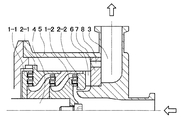
回転型乳化分散装置はロータの遠心力によりポンプの機能があるので、従来型の原理は図3のように、また、本発明の原理は図1のように示す事が出来る。即ち、構造図4に示したように、従来の初段目ステーター2−2の前にステーターの内円と外円を貫通した還流通路6を設け、終段目ロータ1−1から出た被処理物はこの還流通路を通して初段目ロータ1−2の吸込み口に還流して圧力をそこで釈放出来るような構造にしている。
Since the rotary emulsifying and dispersing apparatus has a pump function by the centrifugal force of the rotor, the principle of the conventional type can be shown as in FIG. 3, and the principle of the present invention can be shown as in FIG. That is, as shown in FIG. 4, a
上述のように、初段目ステーター2−2の前に内面と外面を貫通した還流通路6を設けたことで、終段目ロータ1−1から出た被処理物の圧力はこの還流通路を通して吸込み口に釈放され、還流通路の隙間を調整することでケーシング5内の圧力はコントロール出来るようになる。また、この還流された被処理物は初段目ロータ1−2の吸込み口に入り再び攪拌分散され、より均一でシャープな分散性能が得られるようになる。
As described above, by providing the
図4に示しているように、本発明は、ベースに固定してあるケーシング5があって、ケーシングに固定してあるステーター2があり、また、ケーシング5の中に自由回転出来るシャフト4があって、シャフトに着装してシャフトと共に回転するロータ1があり、また、初段目のステーター2−2の前に、ステーターの内面と外面を貫通した還流通路6を設けてあり、終段目ロータ1−1から出た被処理物はこの還流通路6を通して初段目ロータ1−2の吸込み口へ戻る事が出来、この還流通路の隙間を調整することでケーシング内の圧力をコントロールする事が出来る構造にしてある。
As shown in FIG. 4, the present invention has a
上述した内循環乳化分散装置の還流通路に、図6に示しているような逆止リリーフ弁9を設置する事で圧力をコントロールする構造にする事も出来る。図2はその原理図であ
る。
It is possible to adopt a structure in which the pressure is controlled by installing a
また、攪拌分散された被処理物はケーシング内で回転しながら吐出口へ流れ、その分散分布状態は比重により回転直径が異なり、図5に示しているように、吐出口3を還流通路の前に移し、還流通路6と吐出口3の間に邪魔板7を設置して、邪魔板に明けてある分級孔8の位置により細かく分散された被処理物だけを通過させ,ほかの部分は還流通路を通して再び攪拌分散させる構造にする事も出来る。
In addition, the agitated and dispersed object to be processed flows into the discharge port while rotating in the casing, and the dispersion distribution state varies in rotation diameter depending on the specific gravity. As shown in FIG. The
本発明は上述した内循環構造により、ロータの段数を増えても回転速度を増えてもケーシング内の圧力が増えずにコントロールすることが出来、メカニカルシールの冷却水に増圧ポンプを設置する必要がなく、また、還流された被処理物は再び攪拌分散され、分散性能を向上することが図れる。 In the present invention, the internal circulation structure described above enables control without increasing the pressure in the casing even if the number of rotor stages is increased or the rotational speed is increased, and it is necessary to install a booster pump in the cooling water of the mechanical seal. In addition, the refluxed workpiece is stirred and dispersed again to improve the dispersion performance.
また、本発明は上述した邪魔板を設置することにより、細かく分散された部分だけを通過させ、ほかの部分を還流させ再び攪拌分散され、乳化分散性能を向上することが図れる。 Further, in the present invention, by installing the baffle plate described above, only the finely dispersed portion is allowed to pass through, and the other portions are refluxed and stirred and dispersed again, thereby improving the emulsifying and dispersing performance.
1-1終段目ロータ
1-2初段目ロータ
2-1終段目ステーター
2-2初段目ステーター
3 吐出口
4 シャフト
5 ケーシング
6 還流通路
7 邪魔板
8 分級孔
9 逆止リリーフ弁
1-1 Final stage rotor
1-2 First stage rotor
2-1 Final stage stator
2-2 First stage stator
3 Discharge port
4 shaft
5 Casing
6 Return passage
7 baffle plate
8 classification hole
9 Check relief valve
Claims (3)
前記ケーシングに収容され、前記被処理物の流路上に並ぶように前記ケーシングに配置された複数のステーターと、
前記ケーシングに収容され、前記複数のステーターの各々に各々対向する位置に配置された複数のロータであって、前記ステーターに対し突起する歯を有し、前記ステーターに対向した状態で一の軸の周りに回転する複数のロータと、
前記ケーシングに収容され、前記複数のステーターと前記複数のロータとのアセンブリが前記被処理物を吐出するための吐出口から前記アセンブリが前記被処理物を吸い込むための吸込み口へと前記アセンブリを通過した前記被処理物が環流するための環流通路と、
前記環流通路を流れる前記被処理物の流量を調整する流量調整部と
を備える回転型乳化分散装置。 A casing having a suction port for sucking a workpiece from outside and a discharge port for discharging the workpiece to the outside;
A plurality of stators housed in the casing and arranged in the casing so as to line up on the flow path of the workpiece;
A plurality of rotors housed in the casing and disposed at positions facing each of the plurality of stators, each having a tooth protruding from the stator, and having a single shaft in a state facing the stator. Multiple rotors rotating around,
An assembly of the plurality of stators and the plurality of rotors housed in the casing passes through the assembly from a discharge port for discharging the workpiece to a suction port for sucking the workpiece. A recirculation passage for recirculating the workpiece to be treated;
A rotary emulsification dispersion apparatus comprising: a flow rate adjusting unit that adjusts a flow rate of the object to be processed flowing through the circulation path.
請求項1に記載の回転型乳化分散装置。 The rotary emulsification dispersion apparatus according to claim 1, wherein the flow rate adjusting unit is a check valve provided on the reflux passage.
請求項1または2に記載の回転型乳化分散装置。
The assembly includes a baffle plate disposed between the discharge port for discharging the object to be processed and the discharge port for discharging the object to be processed to the outside and having a classification hole. Item 3. The rotary emulsification dispersion apparatus according to Item 1 or 2.
Priority Applications (3)
| Application Number | Priority Date | Filing Date | Title |
|---|---|---|---|
| JP2008273489A JP5408825B2 (en) | 2008-10-23 | 2008-10-23 | Internal circulation emulsification disperser |
| US12/604,341 US8702298B2 (en) | 2008-10-23 | 2009-10-22 | Inner-circulation emulsifying and dispersing arrangement |
| EP09173991A EP2179783A3 (en) | 2008-10-23 | 2009-10-23 | Rotary Emulsifying and Dispersing Apparatus |
Applications Claiming Priority (1)
| Application Number | Priority Date | Filing Date | Title |
|---|---|---|---|
| JP2008273489A JP5408825B2 (en) | 2008-10-23 | 2008-10-23 | Internal circulation emulsification disperser |
Publications (3)
| Publication Number | Publication Date |
|---|---|
| JP2010099592A JP2010099592A (en) | 2010-05-06 |
| JP2010099592A5 JP2010099592A5 (en) | 2011-12-22 |
| JP5408825B2 true JP5408825B2 (en) | 2014-02-05 |
Family
ID=41595160
Family Applications (1)
| Application Number | Title | Priority Date | Filing Date |
|---|---|---|---|
| JP2008273489A Expired - Fee Related JP5408825B2 (en) | 2008-10-23 | 2008-10-23 | Internal circulation emulsification disperser |
Country Status (3)
| Country | Link |
|---|---|
| US (1) | US8702298B2 (en) |
| EP (1) | EP2179783A3 (en) |
| JP (1) | JP5408825B2 (en) |
Families Citing this family (6)
| Publication number | Priority date | Publication date | Assignee | Title |
|---|---|---|---|---|
| DE102007054233B4 (en) * | 2007-11-12 | 2010-06-10 | Ika-Werke Gmbh & Co. Kg | Device for dispersing or homogenizing |
| JP5408825B2 (en) * | 2008-10-23 | 2014-02-05 | 中外ハイテック有限会社 | Internal circulation emulsification disperser |
| WO2010125558A1 (en) * | 2009-04-28 | 2010-11-04 | The State Of Israel, Ministry Of Agriculture & Rural Development, Agricultural Research Organization, (A.R.O.), The Volcani Center | Emulsions, emulsifier, method of use and production process |
| CN105618190A (en) * | 2016-01-30 | 2016-06-01 | 太仓液压元件有限公司 | Low-energy-consumption colloid grinder type emulsifying machine |
| US10596531B1 (en) * | 2016-04-21 | 2020-03-24 | Michael A. Ellis | Modular continuous adhesive foam mixer |
| DE102017113890A1 (en) * | 2017-06-22 | 2018-12-27 | Ika-Werke Gmbh & Co. Kg | Fumigation reactor and method for producing a gas-liquid mixture |
Family Cites Families (29)
| Publication number | Priority date | Publication date | Assignee | Title |
|---|---|---|---|---|
| US2477929A (en) * | 1946-11-12 | 1949-08-02 | California Research Corp | Fluid mixing device |
| US2961223A (en) * | 1957-04-25 | 1960-11-22 | American Viscose Corp | Additive injecting and blending apparatus for filament spinning |
| JPS5221506B2 (en) | 1974-05-01 | 1977-06-10 | ||
| JPS50148343U (en) * | 1974-05-28 | 1975-12-09 | ||
| JPS5940494B2 (en) * | 1981-03-13 | 1984-10-01 | 富士産業株式会社 | Homogenizer mechanism in “stir” mixer |
| FR2596291B1 (en) * | 1986-03-27 | 1990-09-14 | Schlumberger Cie Dowell | POWDER MATERIAL AND LIQUID MIXER, ESPECIALLY CEMENT AND WATER, OR LIQUID-LIQUID |
| JPH0820766B2 (en) * | 1989-03-29 | 1996-03-04 | バンドー化学株式会社 | Toner for developing electrostatic latent image and manufacturing method thereof |
| JPH0526138A (en) | 1991-07-17 | 1993-02-02 | Toyota Motor Corp | Ignition timing controller |
| JP2569727Y2 (en) * | 1991-09-02 | 1998-04-28 | 三井鉱山株式会社 | Disperser structure |
| DE4137179C2 (en) | 1991-11-12 | 1997-02-27 | Hdc Ag | Device for producing a water-in-oil emulsion and use of the device on a diesel engine |
| IT1257704B (en) | 1991-12-05 | 1996-02-01 | Nocchi Pompe Spa | MULTI-FUNCTIONAL WATER PUMP: CENTRIFUGAL, FOR DEEP SUCTION, SELF-PRIMING, CENTRIFUGAL WITH PRESSURE REGULATION, SELF-PRIMING WITH PRESSURE REGULATION, WITH STARTING DEVICE AND / OR AUTOMATIC STOP |
| AU6280294A (en) | 1992-11-02 | 1994-05-24 | Anatoly Fedorovich Kladov | Process for cracking crude oil and petroleum products and a device for carrying out the same |
| AU6280394A (en) * | 1992-11-02 | 1994-05-24 | Anatoly Fedorovich Kladov | Ultrasonic activator |
| GB9717400D0 (en) | 1997-08-15 | 1997-10-22 | Boc Group Plc | Vacuum pumping systems |
| FR2776342B1 (en) | 1998-03-18 | 2001-04-20 | Sarl Cg Promo Star | CENTRIFUGAL PUMP WITH AUTOMATIC PRIMING |
| EP1261416A1 (en) * | 2000-01-31 | 2002-12-04 | Stelzer, C. Ekkehard, Dr. | Mixing method and apparatus |
| JP2002304004A (en) * | 2001-04-09 | 2002-10-18 | Konica Corp | Flat toner, manufacture of the same and image forming method using the flat toner |
| US7090391B2 (en) * | 2002-09-25 | 2006-08-15 | Reika Kogyo Kabushiki Kaisha | Apparatus and method for mixing by agitation in a multichambered mixing apparatus including a pre-agitation mixing chamber |
| DE602006011824D1 (en) * | 2005-07-07 | 2010-03-11 | Rohm & Haas | Process for producing sludge |
| US20070025178A1 (en) * | 2005-07-27 | 2007-02-01 | Xerox Corporation | Pigment dispersions and preparation method thereof |
| JP2008114151A (en) * | 2006-11-02 | 2008-05-22 | Anemosu:Kk | Fluid mixer and mixing element member |
| US8080684B2 (en) * | 2007-06-27 | 2011-12-20 | H R D Corporation | Method of producing ethyl acetate |
| US7749481B2 (en) * | 2007-06-27 | 2010-07-06 | H R D Corporation | System and process for gas sweetening |
| US8518186B2 (en) * | 2007-06-27 | 2013-08-27 | H R D Corporation | System and process for starch production |
| US7842184B2 (en) * | 2007-06-27 | 2010-11-30 | H R D Corporation | Process for water treatment using high shear device |
| DE102007061688A1 (en) * | 2007-12-19 | 2009-06-25 | Bayer Materialscience Ag | Process and mixing unit for the production of isocyanates by phosgenation of primary amines |
| US7906011B2 (en) * | 2008-06-13 | 2011-03-15 | Asphalt Technology Llc | Methods and systems for manufacturing modified asphalts |
| WO2010002534A2 (en) * | 2008-07-03 | 2010-01-07 | H R D Corporation | High shear rotary fixed bed reactor |
| JP5408825B2 (en) * | 2008-10-23 | 2014-02-05 | 中外ハイテック有限会社 | Internal circulation emulsification disperser |
-
2008
- 2008-10-23 JP JP2008273489A patent/JP5408825B2/en not_active Expired - Fee Related
-
2009
- 2009-10-22 US US12/604,341 patent/US8702298B2/en not_active Expired - Fee Related
- 2009-10-23 EP EP09173991A patent/EP2179783A3/en not_active Withdrawn
Also Published As
| Publication number | Publication date |
|---|---|
| EP2179783A3 (en) | 2011-04-13 |
| US20100103767A1 (en) | 2010-04-29 |
| US8702298B2 (en) | 2014-04-22 |
| EP2179783A2 (en) | 2010-04-28 |
| JP2010099592A (en) | 2010-05-06 |
Similar Documents
| Publication | Publication Date | Title |
|---|---|---|
| JP5408825B2 (en) | Internal circulation emulsification disperser | |
| CN106687694A (en) | Direct drive double turbo blower cooling structure | |
| KR20180106828A (en) | A cooling fan and seat cooling system having the same | |
| EP2602489A2 (en) | Fan device, household appliance and method for cooling a motor of a fan device | |
| JP4894900B2 (en) | Blower fan and blower using the same | |
| US8328510B2 (en) | Sealing device for rotary fluid machine, and rotary fluid machine | |
| US7354240B2 (en) | Centrifugal turbo machine with axial thrust control member | |
| US10865799B2 (en) | Centrifugal compression test device | |
| JP2010099592A5 (en) | ||
| JP5339565B2 (en) | Fluid machinery | |
| WO2014122819A1 (en) | Centrifugal compressor | |
| JP2001073993A (en) | Centrifugal fluid machinery | |
| CN110291296B (en) | Cooling fan and seat cooling device with same | |
| CN213628035U (en) | Horizontal multi-stage centrifugal pump | |
| CN111201378B (en) | Impeller for sewage pump | |
| CN106438377B (en) | Vertical multi-stage bivalve centrifugal pump and its application method | |
| US11788533B2 (en) | Multistage centrifugal pump | |
| KR102463299B1 (en) | Compressor housing with piping for recirculating process gas | |
| JP6932516B2 (en) | Centrifugal pump | |
| KR200332249Y1 (en) | High efficiency and low noise type centrifugal fan | |
| JP2018135816A (en) | Centrifugal Pump | |
| KR102000258B1 (en) | 2 step radial blower | |
| JP2019056344A (en) | Centrifugal pump | |
| JP2011174398A (en) | Double casing pump and method of adjusting performance of the same | |
| US20060239811A1 (en) | Apparatus and method for processing fluids |
Legal Events
| Date | Code | Title | Description |
|---|---|---|---|
| A521 | Written amendment |
Free format text: JAPANESE INTERMEDIATE CODE: A523 Effective date: 20111015 |
|
| A621 | Written request for application examination |
Free format text: JAPANESE INTERMEDIATE CODE: A621 Effective date: 20111015 |
|
| A521 | Written amendment |
Free format text: JAPANESE INTERMEDIATE CODE: A523 Effective date: 20111104 |
|
| RD02 | Notification of acceptance of power of attorney |
Free format text: JAPANESE INTERMEDIATE CODE: A7422 Effective date: 20111104 |
|
| A977 | Report on retrieval |
Free format text: JAPANESE INTERMEDIATE CODE: A971007 Effective date: 20121122 |
|
| A131 | Notification of reasons for refusal |
Free format text: JAPANESE INTERMEDIATE CODE: A131 Effective date: 20121129 |
|
| A131 | Notification of reasons for refusal |
Free format text: JAPANESE INTERMEDIATE CODE: A131 Effective date: 20130725 |
|
| A521 | Written amendment |
Free format text: JAPANESE INTERMEDIATE CODE: A523 Effective date: 20130919 |
|
| TRDD | Decision of grant or rejection written | ||
| A01 | Written decision to grant a patent or to grant a registration (utility model) |
Free format text: JAPANESE INTERMEDIATE CODE: A01 Effective date: 20131010 |
|
| A61 | First payment of annual fees (during grant procedure) |
Free format text: JAPANESE INTERMEDIATE CODE: A61 Effective date: 20131104 |
|
| R150 | Certificate of patent or registration of utility model |
Ref document number: 5408825 Country of ref document: JP Free format text: JAPANESE INTERMEDIATE CODE: R150 |
|
| R250 | Receipt of annual fees |
Free format text: JAPANESE INTERMEDIATE CODE: R250 |
|
| R250 | Receipt of annual fees |
Free format text: JAPANESE INTERMEDIATE CODE: R250 |
|
| LAPS | Cancellation because of no payment of annual fees |