JP5407974B2 - Video encoding apparatus and motion vector detection method - Google Patents
Video encoding apparatus and motion vector detection method Download PDFInfo
- Publication number
- JP5407974B2 JP5407974B2 JP2010068196A JP2010068196A JP5407974B2 JP 5407974 B2 JP5407974 B2 JP 5407974B2 JP 2010068196 A JP2010068196 A JP 2010068196A JP 2010068196 A JP2010068196 A JP 2010068196A JP 5407974 B2 JP5407974 B2 JP 5407974B2
- Authority
- JP
- Japan
- Prior art keywords
- motion vector
- prediction
- image
- unit
- picture
- Prior art date
- Legal status (The legal status is an assumption and is not a legal conclusion. Google has not performed a legal analysis and makes no representation as to the accuracy of the status listed.)
- Expired - Fee Related
Links
Images


Landscapes
- Compression Or Coding Systems Of Tv Signals (AREA)
- Image Analysis (AREA)
Description
本発明は、動画像符号化装置及び動きベクトル検出方法に関する。 The present invention relates to a moving image encoding apparatus and a motion vector detection method.
動画像データはデータ量が大きいため、送信装置から受信装置へ伝送される際、あるいは記憶装置に格納される際には、圧縮符号化処理が施されることが多い。代表的な動画像の圧縮符号化方式として、ISO/IEC(International Standardization Organization/International Electrotechnical Commission)で策定されたMPEG(Moving Picture Experts Group)−2/MPEG−4が広く利用されている。また、ITU(国際電気通信連合)とISO/IECのMPEGによって策定された、H.264/AVC(Advanced Video Coding)が知られている。 Since moving image data has a large amount of data, compression encoding processing is often performed when it is transmitted from a transmission device to a reception device or stored in a storage device. As a typical moving image compression encoding method, MPEG (Moving Picture Experts Group) -2 / MPEG-4 established by ISO / IEC (International Standardization Organization / International Electrotechnical Commission) is widely used. In addition, H.264 was established by MPEG of ITU (International Telecommunication Union) and ISO / IEC. H.264 / AVC (Advanced Video Coding) is known.
これらの圧縮符号化方式における動きベクトルの検出処理では、符号化対象のピクチャにおいて、マクロブロックごとに参照ピクチャに対する物体の位置座標(動きベクトル)が評価され、最も類似している部分の動きベクトルが検出される。類似度の評価値としては、予測対象のマクロブロックの画素と空間的に近い位置にある参照ピクチャの画素の値の差分の絶対値を、マクロブロックの全画素に関して加えたSAD(差分絶対値和)が主として用いられる。 In the motion vector detection processing in these compression coding systems, in the picture to be coded, the position coordinates (motion vectors) of the object with respect to the reference picture are evaluated for each macroblock, and the motion vector of the most similar part is determined. Detected. As an evaluation value of similarity, an SAD (sum of absolute differences) obtained by adding an absolute value of a difference between pixels of a reference picture located spatially close to a pixel of a macroblock to be predicted with respect to all pixels of the macroblock ) Is mainly used.
たとえば、H.264/AVCなどにおいては、符号化の際、画面内予測を行うIピクチャ、前方向予測を行うPピクチャ、前方向予測と後方向予測の両方を行うBピクチャの3種類のピクチャが存在する。Bピクチャでは複数の参照ピクチャの中から最適な動きベクトルを検出する必要があり、演算量が多くなる。 For example, H.M. In H.264 / AVC and the like, there are three types of pictures at the time of encoding: an I picture that performs intra prediction, a P picture that performs forward prediction, and a B picture that performs both forward and backward prediction. In the B picture, it is necessary to detect an optimal motion vector from a plurality of reference pictures, and the amount of calculation increases.
演算量削減の方法として、階層的な動きベクトル検出方法が知られている。この方法では、たとえば、フレームの画素を間引いて生成した縮小画像を用いて動きベクトルを検出し(前処理検出)、検出した動きベクトルを中心に元の画像で、前方向予測、後方向予測における1画素精度の動きベクトルを検出する(主検出)。 Hierarchical motion vector detection methods are known as methods for reducing the amount of computation. In this method, for example, a motion vector is detected using a reduced image generated by thinning out the pixels of a frame (preprocessing detection), and the original image is centered on the detected motion vector, and forward prediction and backward prediction are performed. A motion vector with 1 pixel accuracy is detected (main detection).
また、参照ピクチャのインデックス番号を符号化する際に必要なビットに応じて、動きベクトルの検出の際に選択する参照ピクチャを決定することが知られている。 It is also known to determine a reference picture to be selected when detecting a motion vector according to a bit necessary for encoding an index number of a reference picture.
しかしながら、縮小画像ではSADの信頼性が低いため、SADをもとに求められる動きベクトルの精度が低下し、画質の劣化が生じるといった問題があった。
たとえば、画素値のばらつきが大きい原画像から、画素を一定間隔で間引いたり、一定領域ごとの画素値を平均化して生成した縮小画像を用いてSADを計算すると、正しい動きベクトルが得られない可能性があるからである。
However, since the reliability of the SAD is low in the reduced image, there is a problem that the accuracy of the motion vector required based on the SAD is lowered and the image quality is deteriorated.
For example, if SAD is calculated from a reduced image generated by thinning out pixels at regular intervals or averaging pixel values for each constant area from an original image with large variations in pixel values, a correct motion vector may not be obtained. Because there is sex.
上記の点を鑑みて、本発明は、画質の劣化を抑制しつつ、動きベクトル検出における演算量を削減可能な動画像符号化装置及び動きベクトル検出方法を提供することを目的とする。 In view of the above points, an object of the present invention is to provide a moving picture coding apparatus and a motion vector detection method capable of reducing the amount of calculation in motion vector detection while suppressing deterioration in image quality.
上記目的を達成するために、以下のような動画像符号化装置が提供される。
この動画像符号化装置は、符号化対象の画像を縮小した縮小画像を用いて第1の動きベクトルの検出を行う第1の動きベクトル検出部と、検出された前記第1の動きベクトルの確からしさを判定する動きベクトル判定部と、確からしさの判定結果をもとに、正しいと判定された前記第1の動きベクトルの予測方向を選択する予測方向選択部と、元の前記画像において、選択された前記予測方向で第2の動きベクトルの検出を行う第2の動きベクトル検出部と、を有する。
In order to achieve the above object, the following moving picture encoding apparatus is provided.
The moving image encoding apparatus includes a first motion vector detecting unit that detects a first motion vector using a reduced image obtained by reducing an image to be encoded, and a confirmation of the detected first motion vector. A motion vector determination unit that determines the likelihood, a prediction direction selection unit that selects a prediction direction of the first motion vector determined to be correct based on the determination result of the probability, and a selection in the original image And a second motion vector detection unit that detects a second motion vector in the predicted direction.
また、上記目的を達成するために、以下のような動きベクトル検出方法が提供される。
この動きベクトル検出方法は、符号化対象の画像を縮小した縮小画像を用いて第1の動きベクトルの検出を行い、検出された前記第1の動きベクトルの確からしさを判定し、確からしさの判定結果をもとに、正しいと判定された前記第1の動きベクトルの予測方向を選択し、元の前記画像において、選択された前記予測方向で第2の動きベクトルの検出を行う。
In order to achieve the above object, the following motion vector detection method is provided.
In this motion vector detection method, a first motion vector is detected using a reduced image obtained by reducing an image to be encoded, the probability of the detected first motion vector is determined, and the probability is determined. Based on the result, the prediction direction of the first motion vector determined to be correct is selected, and the second motion vector is detected in the original prediction direction in the original image.
開示の動画像符号化装置及び動きベクトル検出方法によれば、画質の劣化を抑止しつつ、動きベクトル検出における演算量を削減できる。 According to the disclosed moving image coding apparatus and motion vector detection method, it is possible to reduce the amount of calculation in motion vector detection while suppressing deterioration in image quality.
以下、本発明の実施の形態を、図面を参照しつつ説明する。
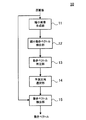
図1は、本実施の形態の動画像符号化装置の主要部の構成を示す図である。
動画像符号化装置10は、縮小画像生成部11、縮小動きベクトル検出部12、動きベクトル判定部13、予測方向選択部14、動きベクトル検出部15を有している。
Hereinafter, embodiments of the present invention will be described with reference to the drawings.
FIG. 1 is a diagram showing a configuration of a main part of the moving picture coding apparatus according to the present embodiment.
The moving
縮小画像生成部11は、画像1フレームを図示しないフレームメモリから読み出し、縮小画像を生成する。たとえば、縮小画像生成部11は、元の画像を縦1/n、横1/nに縮小する。具体的な縮小の例については後述する。
The reduced
縮小動きベクトル検出部12は、生成された縮小画像を用いて動きベクトルの検出を行う。ここでは、縮小動きベクトル検出部12は、たとえば、各フレームの縮小画像間のSADをマクロブロックごとに計算して、動きベクトルを検出する。
The reduced motion
動きベクトル判定部13は、検出された動きベクトルの確からしさを判定する。動きベクトル判定部13は、判定対象のマクロブロックの動きベクトルを、隣接するマクロブロックの動きベクトルと比較して、その確からしさを判定する。詳細は後述する。
The motion
予測方向選択部14は、確からしさの判定結果をもとに、正しいと判定された動きベクトルの予測方向を選択する。Bピクチャの場合、前方向予測と後方向予測があるが、前方向予測で得られた動きベクトルが正しく、後方向予測で得られた動きベクトルが正しくないと判定された場合、予測方向選択部14は、予測方向として前方向を選択する。
The prediction
動きベクトル検出部15は、元の画像において、選択された予測方向で動きベクトル検出を行う。
このように、本実施の形態の動画像符号化装置10は、縮小画像をもとに検出されたベクトルの確からしさを判定して、正しいと判定された動きベクトルの予測方向で、元の画像の動きベクトルの検出を行う。これにより、動きベクトル検出の際の予測方向を限定できるため、演算量を削減できる。また、縮小画像をもとに検出されたベクトルの確からしさを判定して、正しいと判定された動きベクトルの予測方向を用いるため、精度よく動きベクトルを検出でき、画質の劣化を抑制できる。
The motion
As described above, the moving
以下、本実施の形態の動画像符号化装置10による動きベクトル検出方法を、より具体的に説明する。
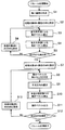
図2は、動きベクトル検出方法の一例を示すフローチャートである。
Hereinafter, the motion vector detection method by the moving
FIG. 2 is a flowchart illustrating an example of a motion vector detection method.
縮小画像生成部11は、1フレームの符号化対象画像を図示しないフレームメモリから読み出し、縮小画像を生成する(ステップS1)。
図3は、ピクチャの並びの一例を示す図である。
The reduced
FIG. 3 is a diagram illustrating an example of a sequence of pictures.
ここでは、時間軸に沿って、I0/P0ピクチャ20、B1ピクチャ21、B2ピクチャ22、I3/P3ピクチャ23と、フレームごとに原画像が順に現れる場合について示されている。ただし、このような入力ピクチャは符号化順に並び変えられる。つまりB1ピクチャ21、B2ピクチャ22の符号化の際に、時間的に後に入力されるI3/P3ピクチャ23が参照ピクチャとして用いられる場合があるので、I3/P3ピクチャ23がこれらBピクチャよりも先の符号化順となる。
Here, the case where the original images appear in order for each frame, such as the I0 / P0 picture 20, the
縮小画像生成部11は、上記のようなフレームの各画素P(x,y)に対して、以下のような式(1)でPa(x,y)を計算する。
The reduced
式(1)において、xは水平方向の座標、yは垂直方向の座標、a(i,j)は係数を示す。a(i,j)は低周波通過フィルタとなるような値を用いることが望ましく、たとえば、i,jの値によらずa(i,j)=1/49などとしてもよい。 In Equation (1), x is a horizontal coordinate, y is a vertical coordinate, and a (i, j) is a coefficient. It is desirable to use a value that becomes a low-frequency pass filter for a (i, j). For example, a (i, j) = 1/49 may be used regardless of the value of i, j.
そして、縮小画像生成部11は、算出されたPa(x,y)のうち、x=4m+a、y=4m+b(mは0以上の整数、a、bは0以上3以下の任意の整数)の画素をサンプリングし、これを縮小画像として、図示しないフレームメモリに保存する。
Then, the reduced
図4は、1フレームの画像(原画像)と縮小画像の一例を示す図である。
図中の白丸と黒丸は画素を示しており、黒丸の画素は縮小画像の生成の際にサンプリングされる画素を示している。また、横軸がx方向の画素の位置、縦軸がy方向の画素の位置を示している。
FIG. 4 is a diagram illustrating an example of an image (original image) and a reduced image of one frame.
In the figure, white circles and black circles indicate pixels, and black circle pixels indicate pixels sampled when a reduced image is generated. Further, the horizontal axis indicates the position of the pixel in the x direction, and the vertical axis indicates the position of the pixel in the y direction.
この例の場合、縮小画像生成部11は、x=4m+1、y=4m+1の画素をサンプリングすることで、元の画像に対して1/4の縮小率の縮小画像を生成している。
上記のように、低周波通過フィルタを通すことで、高周波成分の折り返し歪みや、ノイズの影響を抑制した縮小画像を生成することができ、後述する縮小動きベクトルの検出精度が高まる。
In the case of this example, the reduced
As described above, by passing through the low-frequency pass filter, it is possible to generate a reduced image in which the aliasing distortion of the high-frequency component and the influence of noise are suppressed, and the detection accuracy of the reduced motion vector described later is increased.
次に、縮小動きベクトル検出部12による動き検出が行われる。なお、以下の説明では、Bピクチャ(図3に示したような、B1ピクチャ21またはB2ピクチャ22)に関する動きベクトルの検出方法について説明する。
Next, motion detection by the reduced motion
まず、縮小動きベクトル検出部12は、縮小画像生成部11で生成された縮小画像をマクロブロック(図2中ではMBと表記している)に分割して、最初のマクロブロックを処理対象マクロブロックとして設定する(ステップS2)。
First, the reduced motion
そして、縮小動きベクトル検出部12は、処理対象マクロブロックに対して、まず前方向予測による動きベクトル検出を行う(ステップS3)。たとえば、処理対象マクロブロックが、図3に示したB1ピクチャ21の縮小画像に属する場合は、B1ピクチャ21に対して時間的に前方向にあるI0/P0ピクチャ20の縮小画像が参照ピクチャとなる。この場合、縮小動きベクトル検出部12は、たとえば、処理対象マクロブロックと、I0/P0ピクチャ20の縮小画像の探索範囲内のそれぞれの画素との間で、SADを計算する。
Then, the reduced motion
SADは以下の式で求められる。 SAD is obtained by the following equation.
ここで、c(i,j)は処理対象マクロブロックの(i,j)の位置に存在する画素の値を示し、r(x+i,y+j)は、参照ピクチャにおいて(i,j)から水平方向にx、垂直方向にyだけ離れた(x+i,y+j)の位置に存在する画素の値を示す。また、nは処理対象マクロブロックの水平方向の画素数、mは処理対象マクロブロックの垂直方向の画素数である。縦横16×16画素をマクロブロックとしている原画像を1/4に縮小する場合は、n=m=4となる。また、水平方向を1/4、垂直方向を1/2の縮小率で原画像を縮小する場合には、n=4、m=8となる。 Here, c (i, j) indicates the value of the pixel existing at the position (i, j) of the processing target macroblock, and r (x + i, y + j) is the horizontal direction from (i, j) in the reference picture. Represents the value of a pixel present at a position (x + i, y + j) separated by x and y in the vertical direction. Further, n is the number of pixels in the horizontal direction of the processing target macroblock, and m is the number of pixels in the vertical direction of the processing target macroblock. When an original image having 16 × 16 pixels vertically and horizontally as a macroblock is reduced to ¼, n = m = 4. When the original image is reduced at a reduction ratio of 1/4 in the horizontal direction and 1/2 in the vertical direction, n = 4 and m = 8.
そして、縮小動きベクトル検出部12は、探索範囲内の各画素に対して求められたSADのうち、最も小さいSADを示す(x,y)を動きベクトルとして検出する。
次に、縮小動きベクトル検出部12は、処理対象マクロブロックに対して、後方向予測による動きベクトル検出を行う(ステップS4)。
Then, the reduced motion
Next, the reduced motion
たとえば、処理対象マクロブロックが、図3に示したB1ピクチャ21の縮小画像に属する場合は、B1ピクチャ21に対して時間的に後方向にあるI3/P3ピクチャ23の縮小画像が参照ピクチャとなる。この場合、縮小動きベクトル検出部12は、処理対象マクロブロックと、I3/P3ピクチャ23の縮小画像の探索範囲内のそれぞれの画素との間で、前述の式(2)によりSADを計算する。
For example, when the processing target macroblock belongs to the reduced image of the
そして、縮小動きベクトル検出部12は、探索範囲内の各画素に対して求められたSADのうち、最も小さいSADを示す(x,y)を動きベクトルとして検出する。
こうして検出された各方向の動きベクトルの情報は、たとえば、図示しないメモリなどに保持される。
Then, the reduced motion
The information on the motion vector detected in each direction is held in a memory (not shown), for example.
縮小動きベクトル検出部12は、生成した縮小画像の全てのマクロブロックに対して動きベクトルの検出処理が終了したか判定し(ステップS5)、終了していなければ、処理対象のマクロブロックとして次のマクロブロックを設定する(ステップS6)。そして、縮小動きベクトル検出部12は、全マクロブロックの動きベクトルの検出が終了するまで、ステップS3〜S6の処理を繰り返す。
The reduced motion
縮小画像での動きベクトルの検出が終了すると、動きベクトル判定部13の処理が開始される。ここで動きベクトル判定部13は、まず、最初のマクロブロックを処理対象マクロブロックとして設定し(ステップS7)、処理対象マクロブロックに対して動きベクトルの確からしさの判定を行う(ステップS8)。
When the detection of the motion vector in the reduced image is completed, the process of the motion
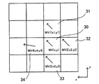
図5は、動きベクトルの確からしさの判定動作の具体例を示す図である。
ここでは、縮小画像におけるマクロブロック30の動きベクトルMVの確からしさを判定する例を示す。図5では、動きベクトルMVのx成分及びy成分を(x,y)と示している。
FIG. 5 is a diagram illustrating a specific example of the motion vector probability determination operation.
Here, an example is shown in which the likelihood of the motion vector MV of the
動きベクトル判定部13は、処理対象のマクロブロック30に隣接するマクロブロック31,32,33,34の動きベクトルMV1,MV2,MV3,MV4をもとに、動きベクトルMVの確からしさを判定する。
The motion
処理対象のマクロブロック30に対して上に隣接するマクロブロック31の動きベクトルMV1のx成分及びy成分を(x1,y1)、右に隣接するマクロブロック32の動きベクトルMV2のx成分及びy成分を(x2,y2)としている。また、処理対象のマクロブロック30に対して下に隣接するマクロブロック33の動きベクトルMV3のx成分及びy成分を(x3,y3)、左に隣接するマクロブロック34の動きベクトルMV4のx成分及びy成分を(x4,y4)としている。
The x and y components of the motion vector MV1 of the
動きベクトル判定部13は、まず、マクロブロック30に隣接するマクロブロック31〜34の動きベクトルMV1〜MV4の各成分の最小値及び最大値を求める。
x方向の最小値は、MINx=MIN(x1,x2,x3,x4)、y方向の最小値は、MINy=MIN(y1,y2,y3,y4)と表す。x方向の最大値は、MAXx=MAX(x1,x2,x3,x4)、y方向の最大値は、MAXy=MAX(y1,y2,y3,y4)と表す。
The motion
The minimum value in the x direction is expressed as MINx = MIN (x1, x2, x3, x4), and the minimum value in the y direction is expressed as MINy = MIN (y1, y2, y3, y4). The maximum value in the x direction is expressed as MAXx = MAX (x1, x2, x3, x4), and the maximum value in the y direction is expressed as MAXy = MAX (y1, y2, y3, y4).
ここで、動きベクトル判定部13は、動きベクトルMVの(x,y)が、x≧MINx、y≧MINy、x≦MAXx、y≦MAXyを全て満たしているか否か判定する。動きベクトル判定部13は、(x,y)がこれらの式を全て満たしている場合には、動きベクトルMVは正しいと判定し、何れか一つでも満たしていない場合には、正しくないと判定する。
Here, the motion
なお、動きベクトル判定部13は、たとえば、上記4つの条件のうち、少なくとも3つを満たしていれば正しいと判定するようにしてもよい。
動きベクトル判定部13は、上記のような判定処理を、前方向予測に基づいて検出された動きベクトルと、後方向予測に基づいて検出された動きベクトルの両方について行う。
The motion
The motion
次に、予測方向選択部14は、動きベクトル判定部13での判定結果をもとに、動きベクトルの予測方向を選択する(ステップS9)。
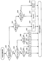
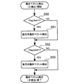
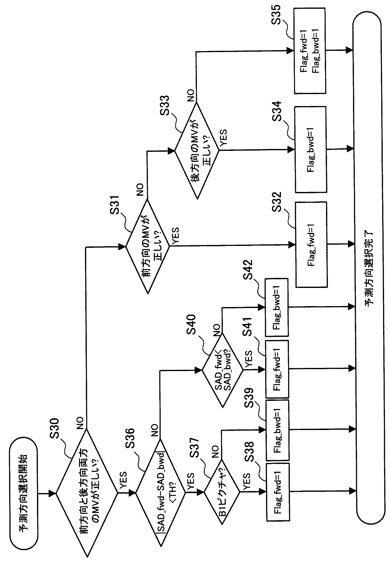
図6は、予測方向の選択処理の流れを示すフローチャートである。
Next, the prediction
FIG. 6 is a flowchart showing the flow of the prediction direction selection process.
Flag_fwdは前方向の予測方向の選択の有無を示すフラグであり、Flag_bwdは後方向の予測方向の選択の有無を示すフラグであり、いずれも初期値は0とする。
まず、予測方向選択部14は、ステップS8の処理の結果、前方向予測と後方向予測に基づき検出された動きベクトルMVが、両方正しいと判断されたか否かを判定する(ステップS30)。ここで、両方の動きベクトルが正しいと判断された場合にはステップS36の処理が行われ、何れか一方または両方の動きベクトルMVが正しくない場合には、ステップS31の処理が行われる。
Flag_fwd is a flag indicating the presence / absence of selection of the forward prediction direction, and Flag_bwd is a flag indicating the presence / absence of selection of the backward prediction direction.
First, the prediction
ステップS31の処理において、予測方向選択部14は、前方向予測に基づき検出された動きベクトルMVが正しいか否か判定する。前方向予測に基づき検出された動きベクトルMVが正しい場合、予測方向選択部14は、Flag_fwd=1とし、前方向の予測方向を選択する(ステップS32)。
In the process of step S31, the prediction
前方向予測に基づき検出された動きベクトルMVが正しくない場合、予測方向選択部14は、後方向予測に基づき検出された動きベクトルMVが正しいか判定する(ステップS33)。後方向予測に基づき検出された動きベクトルMVが正しい場合、予測方向選択部14は、Flag_bwd=1とし、後方向の予測方向を選択する(ステップS34)。
When the motion vector MV detected based on the forward prediction is not correct, the prediction
これにより一方向の予測方向が選択され、次の動きベクトル検出処理(ステップS10)では、縮小画像での動きベクトルが正しくないと判定された予測方向での検出は行われないので、演算量を削減できるとともに、精度よく動きベクトルが検出できる。 As a result, a prediction direction in one direction is selected, and in the next motion vector detection process (step S10), detection in the prediction direction determined that the motion vector in the reduced image is not correct is not performed. It can be reduced and the motion vector can be detected accurately.
ただし、後方向予測に基づき検出された動きベクトルMVも正しくない場合、予測方向選択部14は、Flag_fwd、Flag_bwdを両方とも1とし、予測方向として両方向を選択する(ステップS35)。これにより、次の動きベクトル検出処理では、両方向の予測が行われ、精度よく動きベクトルが検出可能になる。
However, when the motion vector MV detected based on the backward prediction is not correct, the prediction
一方、ステップS30の処理で、前方向予測及び後方向予測に基づき検出された動きベクトルMVが両方とも正しいと判定された場合、予測方向選択部14は、SAD_fwd−SAD_bwdの絶対値が閾値THより小さいか否か判定する(ステップS36)。
On the other hand, when the motion vector MV detected based on the forward prediction and the backward prediction is determined to be both correct in the process of step S30, the prediction
SAD_fwdは、前方向予測に基づき検出された動きベクトルMVを求める際に用いられたSADである。SAD_bwdは、後方向予測に基づき検出された動きベクトルMVを求める際に用いられたSADである。閾値THは、縮小画像でSADを計算することによる誤差に応じた値である。たとえば、16×16画素のマクロブロックの原画像を1/4に縮小した縮小画像を用いた場合、マクロブロックは4×4画素となる。このとき、各画素の値が0〜255であることから、SADは、0≦SAD≦255×16となる。この場合、閾値THとして、画素値のばらつきを考慮すると、100〜200程度の値を用いることが望ましい。 SAD_fwd is SAD used when the motion vector MV detected based on the forward prediction is obtained. SAD_bwd is SAD used when obtaining a motion vector MV detected based on backward prediction. The threshold value TH is a value corresponding to an error caused by calculating SAD with a reduced image. For example, when a reduced image obtained by reducing an original image of a 16 × 16 pixel macroblock to ¼ is used, the macroblock has 4 × 4 pixels. At this time, since the value of each pixel is 0 to 255, SAD is 0 ≦ SAD ≦ 255 × 16. In this case, it is desirable to use a value of about 100 to 200 as the threshold value TH in consideration of variations in pixel values.
予測方向選択部14は、|SAD_fwd−SAD_bwd|<THの場合、前方向予測と後方向予測に基づくSADが、誤差より小さい程度しか差異がないと判定し、SADを用いての予測方向選択を行わない。その代わり、予測方向選択部14は処理対象マクロブロックが、図3で示したようなB1ピクチャ21を縮小した縮小画像内のものであるか否かを判定する(ステップS37)。
When | SAD_fwd−SAD_bwd | <TH, the prediction
B1ピクチャ21は、図3に示したように、前方向予測の参照画像としてI0/P0ピクチャ20を参照し、後方向予測の参照ピクチャとしてI3/P3ピクチャ23を参照する。
As shown in FIG. 3, the
ステップS37の処理で、処理対象マクロブロックが、B1ピクチャ21を縮小した縮小画像内のものであると判定された場合には、予測方向選択部14は、Flag_fwd=1とし、前方向の予測方向を選択する(ステップS38)。これにより、次の元の原画像(等倍の原画像)を用いた動きベクトル検出処理では、この処理対象マクロブロックに対応した等倍(16×16画素)のマクロブロックに対しては、B1ピクチャ21に時間的に近いI0/P0ピクチャ20が参照ピクチャとなる。
If it is determined in the process of step S37 that the processing target macroblock is in the reduced image obtained by reducing the
ステップS37の処理で、処理対象マクロブロックが、B1ピクチャ21を縮小した縮小画像内のものでないと判定された場合には、図3に示したように、処理対象マクロブロックは、B2ピクチャ22を縮小した縮小画像内のものである。この場合、予測方向選択部14は、Flag_bwd=1とし、後方向の予測方向を選択する(ステップS39)。これにより、次の、等倍の原画像を用いた動きベクトル検出処理では、この処理対象マクロブロックに対応した等倍(16×16画素)のマクロブロックに対しては、B2ピクチャ22に時間的に近いI3/P3ピクチャ23が参照ピクチャとなる。
If it is determined in step S37 that the processing target macroblock is not in the reduced image obtained by reducing the
動画像では、フレームとフレームの時間間隔が短いほど、類似度が高くなる。そのため、ステップS37〜S39の処理で、時間的に近いフレームが参照ピクチャとなるように予測方向を選択することで、次の動きベクトル検出処理で、処理対象マクロブロックに、より類似した画像を指し示す動きベクトルを検出できる。また、予測方向選択部14は、一方向の予測方向を選択することで、次の動きベクトル検出処理の演算量を削減できる。
In moving images, the shorter the time interval between frames, the higher the degree of similarity. Therefore, by selecting the prediction direction so that the temporally close frame becomes the reference picture in the processing of steps S37 to S39, the next motion vector detection processing indicates an image more similar to the processing target macroblock. A motion vector can be detected. Moreover, the prediction
一方、ステップS36の処理で、|SAD_fwd−SAD_bwd|<THではない場合、予測方向選択部14は、SAD_fwd<SAD_bwdであるか否かを判定する(ステップS40)。SAD_fwd<SAD_bwdである場合、前方向予測を行った方が動きベクトルの検出精度がよいため、予測方向選択部14は、Flag_fwd=1とし、前方向の予測方向を選択する(ステップS41)。SAD_fwd<SAD_bwdでない場合、後方向予測を行った方が動きベクトルの検出精度がよいため、予測方向選択部14は、Flag_bwd=1とし、後方向の予測方向を選択する(ステップS42)。このように、予測方向選択部14は、一方向の予測方向を選択することで、次の動きベクトル検出処理の演算量を削減できる。
On the other hand, if | SAD_fwd−SAD_bwd | <TH is not satisfied in the process of step S36, the prediction
以上のような処理により予測方向が選択されると、動きベクトル検出部15は、元の等倍の原画像のマクロブロックを用いて、選択された予測方向で動きベクトルの検出を行う(ステップS10)。
When the prediction direction is selected by the process as described above, the motion
図7は、動きベクトル検出(主検出)処理の流れを示すフローチャートである。
動きベクトル検出部15は、ステップS9の処理の結果、選択された予測方向が前方向、すなわち、Flag_fwd=1であるか否か判定する(ステップS50)。Flag_fwd=1である場合、動きベクトル検出部15は、処理対象マクロブロックに対応する等倍のマクロブロック(16×16画素)に対して、前方向予測で動きベクトルの検出を行う(ステップS51)。
FIG. 7 is a flowchart showing the flow of motion vector detection (main detection) processing.
The motion
ステップS51の処理の後、またはステップS50の処理で、Flag_fwd=1ではないと判定された場合、動きベクトル検出部15は、選択された予測方向が後方向(Flag_bwd=1)であるか否か判定する(ステップS52)。Flag_bwd=1である場合、動きベクトル検出部15は、処理対象マクロブロックに対応する等倍のマクロブロック(16×16画素)に対して、後方向予測で動きベクトルの検出を行う(ステップS53)。
After the process of step S51 or when it is determined in the process of step S50 that Flag_fwd = 1 is not true, the motion
図8は、動きベクトル検出の際のピクチャ間の参照関係を示す図である。
矢印aは前方向予測の方向を示しており、矢印bは後方向予測の予測方向を示している。ここでの動きベクトルの検出は、16×16画素のマクロブロック20a,21a,22a,23aごとに行われる。符号化対象がB1ピクチャ21のマクロブロック21aのとき、前方向予測の参照ピクチャとしてI0/P0ピクチャ20を、後ろ方向予測の参照ピクチャとしてI3/P3ピクチャ23が使用可能である。しかし、Flag_fwd=1でFlag_bwd=0の場合には、B1ピクチャ21の動きベクトル検出には、参照ピクチャとして、I0/P0ピクチャ20が用いられ、I3/P3ピクチャ23は用いられない。また、Flag_fwd=0でFlag_bwd=1の場合には、B1ピクチャ21の動きベクトル検出には、参照ピクチャとして、I0/P0ピクチャ20が用いられ、I3/P3ピクチャ23は用いられない。このように、一方向の予測方向で動き検出が行われるので、演算量が少なくて済む。
FIG. 8 is a diagram illustrating a reference relationship between pictures in motion vector detection.
Arrow a indicates the direction of forward prediction, and arrow b indicates the prediction direction of backward prediction. The detection of the motion vector here is performed for each
動きベクトルの検出は、式(2)により算出されるSADを用いて行われる。なお、このとき、マクロブロックは16×16画素であるので、式(2)において、n=m=16となる。 The motion vector is detected using the SAD calculated by equation (2). At this time, since the macroblock is 16 × 16 pixels, n = m = 16 in Expression (2).
ステップS53の処理後、または、ステップS52の処理で、Flag_bwd=1ではない場合には、動きベクトル検出が終了し、図2で示したステップS11の処理が行われる。ステップS11の処理では、処理対象のマクロブロックに対して、動きベクトルが検出された場合、動きベクトル検出部15は、動きベクトルを出力する。
After Step S53, or when Flag_bwd = 1 is not satisfied in Step S52, the motion vector detection ends, and Step S11 shown in FIG. 2 is performed. In the process of step S11, when a motion vector is detected for the macro block to be processed, the motion
その後、動きベクトル判定部13は、全てのマクロブロックの処理が終了したか判定し(ステップS12)、終了していなければ、処理対象のマクロブロックとして次のマクロブロックを設定する(ステップS13)。そして、動きベクトル判定部13、予測方向選択部14、動きベクトル検出部15は、全マクロブロックの動きベクトルの検出が終了するまで、ステップS8〜S13の処理を繰り返す。
Thereafter, the motion
全マクロブロックの動きベクトルの検出が終了すると、このフレームの処理が終了し、次のフレームにおいても同様にステップS1〜13の処理が行われ、動きベクトルが検出される。 When the detection of the motion vectors of all the macroblocks is completed, the processing of this frame is completed, and the processing in steps S1 to S13 is similarly performed in the next frame to detect the motion vector.
以上のような動きベクトル検出方法によれば、縮小画像をもとに検出されたベクトルの確からしさを判定して、正しいと判定された動きベクトルの予測方向で、元の画像の動きベクトルの検出を行う。これにより、Bピクチャにおける動きベクトル検出の際、予測方向を限定できるため、両方向の予測を行う場合と比べて、主検出における演算量を最大で50%削減できる。また、精度よく動きベクトルを検出できるため、画質の劣化を抑制できる。また、参照ピクチャをフレームメモリから読み出す枚数を2枚から1枚に削減できる。 According to the motion vector detection method as described above, the probability of the detected vector is determined based on the reduced image, and the motion vector of the original image is detected in the motion vector prediction direction determined to be correct. I do. Accordingly, since the prediction direction can be limited when detecting a motion vector in a B picture, the amount of calculation in main detection can be reduced by 50% at the maximum compared to the case of performing prediction in both directions. In addition, since the motion vector can be detected with high accuracy, deterioration in image quality can be suppressed. Further, the number of reference pictures read from the frame memory can be reduced from two to one.
以下、動画像符号化装置の一例の全体構成を説明する。
図9は、動画像符号化装置の一例の構成を示す図である。
動画像符号化装置50は、画像並べ替え部51、予測誤差信号生成部52、整数変換部53、量子化部54、エントロピー符号化部55、逆量子化部56、逆整数変換部57、参照ピクチャ生成部58、フィルタ処理部59を有している。さらに動画像符号化装置50は、フレームメモリ60、画面内予測部61、動き検出部62、動き補償部63、予測画像選択部64を有している。なお、動画像符号化装置50の各部を制御する制御部については図示を省略している。
Hereinafter, an overall configuration of an example of a moving image encoding device will be described.
FIG. 9 is a diagram illustrating a configuration of an example of a moving image encoding device.
The moving
画像並べ替え部51は、符号化のために、原画像のフレームをGOP(Group Of Pictures)構造に応じて並べ替える。
予測誤差信号生成部52は、並べ替えられた原画像のフレームにおいて、マクロブロックの画素データと、予測画像選択部64で選択された予測画像のマクロブロックの画素データとの差分を演算することにより、予測誤差信号を生成する。整数変換部53は、予測誤差信号生成部52からの予測誤差信号を整数変換した信号を出力する。量子化部54は、整数変換部53からの出力信号を量子化する。これにより、予測誤差信号の符号量が低減される。
The
The prediction error
エントロピー符号化部55は、量子化部54からの量子化データ、画面内予測部61からの出力データ、動き検出部62から出力される動きベクトルの情報をエントロピー符号化し、符号化画像データを出力する。ここで、エントロピー符号化とは、シンボルの出現頻度に応じて可変長の符号を割り当てる符号化方式を指す。
The
逆量子化部56は、量子化部54からの量子化データを逆量子化する。逆整数変換部57は、逆量子化部56からの出力データに逆整数変換処理を施す。これにより、符号化前の予測誤差信号と同程度の信号が得られる。
The
参照ピクチャ生成部58は、動き補償部63により動き補償されたマクロブロックの画素データと、逆量子化部56及び逆整数変換部57によって復号された予測誤差信号とを加算する。これにより、動き補償された参照ピクチャのマクロブロックが生成される。
The reference
フィルタ処理部59は、マクロブロックのデータに対してデブロッキングフィルタ処理を行い、ブロックノイズの発生を抑制した後、フレームメモリ60に蓄積する。
画面内予測部61は、同じピクチャにおける周辺画素から、予測画像のマクロブロックを生成する。
The
The
動き検出部62は、図1に示した各部の機能を有し、画像並べ替え部51から出力される原画像のマクロブロックと、フレームメモリ60から読み込んだ参照ピクチャのデータをもとに動きベクトルを算出し、出力する。
The
動き補償部63は、動き検出部62から出力された動きベクトルをもとに、フレームメモリ60から読み込んだ参照ピクチャのデータに対して動き補償することにより、動き補償された予測画像のマクロブロックを生成する。
The
予測画像選択部64は、画面内予測部61または動き補償部63のどちらか一方から出力される予測画像のマクロブロックを選択し、予測誤差信号生成部52及び参照ピクチャ生成部58に出力する。
The predicted
このような、動画像符号化装置50の動き検出部62に対して、図1に示したような構成を適用することで、動きベクトル検出における演算量を削減できるため、動画像符号化装置50全体における演算量を削減でき、符号化処理を高速化できる。また、縮小画像における動きベクトルの確からしさを判定して、主検出の動きベクトル検出の際の予測方向を選択しているので高精度に動きベクトルを検出でき、その動きベクトルを用いることで、符号化に伴う画質の劣化を抑制することができる。
Since the calculation amount in motion vector detection can be reduced by applying the configuration shown in FIG. 1 to the
以上、実施の形態に基づき、本発明の動画像符号化装置及び動きベクトル検出方法の一観点について説明してきたが、これらは一例にすぎず、上記の記載に限定されるものではない。 As described above, one aspect of the moving picture coding apparatus and the motion vector detection method of the present invention has been described based on the embodiments. However, these are merely examples, and the present invention is not limited to the above description.
たとえば、上記の説明では、マクロブロックは16×16画素として説明したが、16×8画素、8×16画素、8×8画素、4×8画素、8×4画素、または4×4画素としてもよい。 For example, in the above description, the macro block is described as 16 × 16 pixels, but as 16 × 8 pixels, 8 × 16 pixels, 8 × 8 pixels, 4 × 8 pixels, 8 × 4 pixels, or 4 × 4 pixels. Also good.
また、上記では、Bピクチャの符号化の際に、前方向及び後方向の参照ピクチャを1枚ずつ参照する場合について説明したが、複数枚参照するようにしてもよい。
また、縮小画像を生成する際に、原画像の画素を間引きするのではなく、一定領域ごとの画素値を平均したものを縮小画像の画素値とするようにしてもよい。
In the above description, a case has been described in which one forward reference picture and one backward reference picture are referred to when encoding a B picture, but a plurality of reference pictures may be referred to.
Further, when generating a reduced image, instead of thinning out the pixels of the original image, an average of the pixel values for each predetermined area may be used as the pixel value of the reduced image.
10 動画像符号化装置
11 縮小画像生成部
12 縮小動きベクトル検出部
13 動きベクトル判定部
14 予測方向選択部
15 動きベクトル検出部
DESCRIPTION OF
Claims (5)
判定対象の前記第1の動きベクトルが含まれる前記領域に隣接する複数の前記領域の前記第1の動きベクトルの第1方向成分と第2方向成分の最小値または最大値と、前記判定対象の前記第1の動きベクトルの第1方向成分と第2方向成分との比較結果に基づき、前記判定対象の前記第1の動きベクトルが正しいか否かを判定することで、前記領域ごとに検出された前記第1の動きベクトルの確からしさを判定する動きベクトル判定部と、
確からしさの判定結果をもとに、正しいと判定された前記第1の動きベクトルの予測方向を選択する予測方向選択部と、
元の前記画像において、選択された前記予測方向で第2の動きベクトルの検出を行う第2の動きベクトル検出部と、
を有することを特徴とする動画像符号化装置。 A first motion vector detection unit that divides a reduced image obtained by reducing an image to be encoded into a plurality of regions and detects a first motion vector for each region ;
The minimum or maximum value of the first direction component and the second direction component of the first motion vector of the plurality of regions adjacent to the region including the first motion vector to be determined, and the determination target Based on the comparison result between the first direction component and the second direction component of the first motion vector, it is detected for each region by determining whether or not the first motion vector to be determined is correct. A motion vector determination unit that determines the probability of the first motion vector;
A prediction direction selection unit that selects a prediction direction of the first motion vector determined to be correct based on the determination result of the probability;
A second motion vector detection unit for detecting a second motion vector in the selected prediction direction in the original image;
A moving picture encoding apparatus comprising:
判定対象の前記第1の動きベクトルが含まれる前記領域に隣接する複数の前記領域の前記第1の動きベクトルの第1方向成分と第2方向成分の最小値または最大値と、前記判定対象の前記第1の動きベクトルの第1方向成分と第2方向成分との比較結果に基づき、前記判定対象の前記第1の動きベクトルが正しいか否かを判定することで、前記領域ごとに検出された前記第1の動きベクトルの確からしさを判定し、
確からしさの判定結果をもとに、正しいと判定された前記第1の動きベクトルの予測方向を選択し、
元の前記画像において、選択された前記予測方向で第2の動きベクトルの検出を行うことを特徴とする動きベクトル検出方法。 A reduced image obtained by reducing the image to be encoded is divided into a plurality of regions, and a first motion vector is detected for each region ,
The minimum or maximum value of the first direction component and the second direction component of the first motion vector of the plurality of regions adjacent to the region including the first motion vector to be determined, and the determination target Based on the comparison result between the first direction component and the second direction component of the first motion vector, it is detected for each region by determining whether or not the first motion vector to be determined is correct. Determining the likelihood of the first motion vector;
Based on the determination result of the probability, the prediction direction of the first motion vector determined to be correct is selected,
A motion vector detection method, comprising: detecting a second motion vector in the selected prediction direction in the original image.
Priority Applications (1)
| Application Number | Priority Date | Filing Date | Title |
|---|---|---|---|
| JP2010068196A JP5407974B2 (en) | 2010-03-24 | 2010-03-24 | Video encoding apparatus and motion vector detection method |
Applications Claiming Priority (1)
| Application Number | Priority Date | Filing Date | Title |
|---|---|---|---|
| JP2010068196A JP5407974B2 (en) | 2010-03-24 | 2010-03-24 | Video encoding apparatus and motion vector detection method |
Publications (2)
| Publication Number | Publication Date |
|---|---|
| JP2011205212A JP2011205212A (en) | 2011-10-13 |
| JP5407974B2 true JP5407974B2 (en) | 2014-02-05 |
Family
ID=44881431
Family Applications (1)
| Application Number | Title | Priority Date | Filing Date |
|---|---|---|---|
| JP2010068196A Expired - Fee Related JP5407974B2 (en) | 2010-03-24 | 2010-03-24 | Video encoding apparatus and motion vector detection method |
Country Status (1)
| Country | Link |
|---|---|
| JP (1) | JP5407974B2 (en) |
Families Citing this family (3)
| Publication number | Priority date | Publication date | Assignee | Title |
|---|---|---|---|---|
| JP2015216632A (en) * | 2014-04-22 | 2015-12-03 | ソニー株式会社 | Coding device and coding method |
| JP6390275B2 (en) * | 2014-09-01 | 2018-09-19 | 株式会社ソシオネクスト | Encoding circuit and encoding method |
| JP7147835B2 (en) * | 2018-02-20 | 2022-10-05 | 株式会社ソシオネクスト | Display control device, display control system, display control method, and program |
Family Cites Families (3)
| Publication number | Priority date | Publication date | Assignee | Title |
|---|---|---|---|---|
| JP3050736B2 (en) * | 1993-12-13 | 2000-06-12 | シャープ株式会社 | Video encoding device |
| JP2002232892A (en) * | 2001-02-01 | 2002-08-16 | Sony Corp | Image coding device |
| JP4166781B2 (en) * | 2005-12-09 | 2008-10-15 | 松下電器産業株式会社 | Motion vector detection apparatus and motion vector detection method |
-
2010
- 2010-03-24 JP JP2010068196A patent/JP5407974B2/en not_active Expired - Fee Related
Also Published As
| Publication number | Publication date |
|---|---|
| JP2011205212A (en) | 2011-10-13 |
Similar Documents
| Publication | Publication Date | Title |
|---|---|---|
| CN110809887B (en) | Method and apparatus for motion vector modification for multi-reference prediction | |
| US11736718B2 (en) | Search region for motion vector refinement | |
| JP6545838B2 (en) | Merge candidate block derivation method and apparatus using such method | |
| US9071845B2 (en) | Method and arrangement for video coding | |
| US9100664B2 (en) | Image encoding device, image decoding device, image encoding method, and image decoding method | |
| US20200236387A1 (en) | Limited memory access window for motion vector refinement | |
| KR20110008653A (en) | Motion vector prediction method and image encoding / decoding apparatus and method using same | |
| JP2004336369A (en) | Moving picture coding apparatus, moving picture decoding apparatus, moving picture coding method, moving picture decoding method, moving picture coding program, and moving picture decoding program | |
| US12137210B2 (en) | Image decoding device, image decoding method, and program | |
| JP5560009B2 (en) | Video encoding device | |
| US11290739B2 (en) | Video processing methods and apparatuses of determining motion vectors for storage in video coding systems | |
| JP2016042727A (en) | Moving picture coding device, moving picture coding method and moving picture coding program, and transmission device, transmission method and transmission program | |
| JP4527677B2 (en) | Moving picture coding method, moving picture coding apparatus, moving picture coding program | |
| JP5407974B2 (en) | Video encoding apparatus and motion vector detection method | |
| US12010339B2 (en) | Image decoding device, image decoding method, and program | |
| WO2015008339A1 (en) | Video image encoding device, video image encoding method, video image decoding device, and video image decoding method | |
| JP5725118B2 (en) | Moving picture decoding apparatus, moving picture decoding method, moving picture decoding program, receiving apparatus, receiving method, and receiving program | |
| JP5725106B2 (en) | Moving picture decoding apparatus, moving picture decoding method, moving picture decoding program, receiving apparatus, receiving method, and receiving program | |
| US20240146932A1 (en) | Methods and non-transitory computer readable storage medium for performing subblock-based interprediction | |
| JP6493592B2 (en) | Moving picture encoding apparatus, moving picture encoding method, moving picture encoding program, moving picture decoding apparatus, moving picture decoding method, and moving picture decoding program | |
| JP6311816B2 (en) | Moving picture coding apparatus, moving picture coding method, moving picture coding program, transmission apparatus, transmission method, and transmission program | |
| JP2004088309A (en) | Motion vector detection method, motion vector detection device, video coding method, video coding device, communication device. | |
| JP2014068361A (en) | Moving image encoder, moving image decoder, moving image encoding method, moving image decoding method, moving image encoding program, and moving image decoding program |
Legal Events
| Date | Code | Title | Description |
|---|---|---|---|
| A621 | Written request for application examination |
Free format text: JAPANESE INTERMEDIATE CODE: A621 Effective date: 20130206 |
|
| A977 | Report on retrieval |
Free format text: JAPANESE INTERMEDIATE CODE: A971007 Effective date: 20130626 |
|
| A131 | Notification of reasons for refusal |
Free format text: JAPANESE INTERMEDIATE CODE: A131 Effective date: 20130702 |
|
| A977 | Report on retrieval |
Free format text: JAPANESE INTERMEDIATE CODE: A971007 Effective date: 20130822 |
|
| A521 | Written amendment |
Free format text: JAPANESE INTERMEDIATE CODE: A523 Effective date: 20130902 |
|
| A01 | Written decision to grant a patent or to grant a registration (utility model) |
Free format text: JAPANESE INTERMEDIATE CODE: A01 Effective date: 20131008 |
|
| A61 | First payment of annual fees (during grant procedure) |
Free format text: JAPANESE INTERMEDIATE CODE: A61 Effective date: 20131021 |
|
| LAPS | Cancellation because of no payment of annual fees |