JP5407960B2 - Lever type connector - Google Patents
Lever type connector Download PDFInfo
- Publication number
- JP5407960B2 JP5407960B2 JP2010061236A JP2010061236A JP5407960B2 JP 5407960 B2 JP5407960 B2 JP 5407960B2 JP 2010061236 A JP2010061236 A JP 2010061236A JP 2010061236 A JP2010061236 A JP 2010061236A JP 5407960 B2 JP5407960 B2 JP 5407960B2
- Authority
- JP
- Japan
- Prior art keywords
- housing
- lever
- end edge
- rear end
- type connector
- Prior art date
- Legal status (The legal status is an assumption and is not a legal conclusion. Google has not performed a legal analysis and makes no representation as to the accuracy of the status listed.)
- Expired - Fee Related
Links
Images


Classifications
-
- H—ELECTRICITY
- H01—ELECTRIC ELEMENTS
- H01R—ELECTRICALLY-CONDUCTIVE CONNECTIONS; STRUCTURAL ASSOCIATIONS OF A PLURALITY OF MUTUALLY-INSULATED ELECTRICAL CONNECTING ELEMENTS; COUPLING DEVICES; CURRENT COLLECTORS
- H01R13/00—Details of coupling devices of the kinds covered by groups H01R12/70 or H01R24/00 - H01R33/00
- H01R13/62—Means for facilitating engagement or disengagement of coupling parts or for holding them in engagement
- H01R13/629—Additional means for facilitating engagement or disengagement of coupling parts, e.g. aligning or guiding means, levers, gas pressure electrical locking indicators, manufacturing tolerances
- H01R13/62933—Comprising exclusively pivoting lever
- H01R13/62938—Pivoting lever comprising own camming means
-
- H—ELECTRICITY
- H01—ELECTRIC ELEMENTS
- H01R—ELECTRICALLY-CONDUCTIVE CONNECTIONS; STRUCTURAL ASSOCIATIONS OF A PLURALITY OF MUTUALLY-INSULATED ELECTRICAL CONNECTING ELEMENTS; COUPLING DEVICES; CURRENT COLLECTORS
- H01R13/00—Details of coupling devices of the kinds covered by groups H01R12/70 or H01R24/00 - H01R33/00
- H01R13/62—Means for facilitating engagement or disengagement of coupling parts or for holding them in engagement
- H01R13/629—Additional means for facilitating engagement or disengagement of coupling parts, e.g. aligning or guiding means, levers, gas pressure electrical locking indicators, manufacturing tolerances
- H01R13/62933—Comprising exclusively pivoting lever
- H01R13/62955—Pivoting lever comprising supplementary/additional locking means
-
- H—ELECTRICITY
- H01—ELECTRIC ELEMENTS
- H01R—ELECTRICALLY-CONDUCTIVE CONNECTIONS; STRUCTURAL ASSOCIATIONS OF A PLURALITY OF MUTUALLY-INSULATED ELECTRICAL CONNECTING ELEMENTS; COUPLING DEVICES; CURRENT COLLECTORS
- H01R13/00—Details of coupling devices of the kinds covered by groups H01R12/70 or H01R24/00 - H01R33/00
- H01R13/62—Means for facilitating engagement or disengagement of coupling parts or for holding them in engagement
- H01R13/629—Additional means for facilitating engagement or disengagement of coupling parts, e.g. aligning or guiding means, levers, gas pressure electrical locking indicators, manufacturing tolerances
- H01R13/62933—Comprising exclusively pivoting lever
- H01R13/62966—Comprising two pivoting levers
Landscapes
- Details Of Connecting Devices For Male And Female Coupling (AREA)
Description
本発明は、レバー式コネクタに関する。 The present invention relates to a lever-type connector.
従来のレバー式コネクタが特許文献1に開示されている。このものは、相手ハウジングに嵌合可能とされ、後端面から電線が引き出されるハウジングと、ハウジングに回動可能に装着されるレバーとを備えている。レバーは連結部とその両端部から突出する1対の側板とで門型をなし、ハウジングに後方から跨って装着される。両側板には、カム溝が形成され、相手ハウジングには、カム溝と対応する位置に、カムフォロアが形成されている。カム溝の入り口にカムフォロアが進入した状態で、レバーが回動されることにより、カムフォロアがカム溝に沿って相対変位して倍力作用が発揮され、もって両ハウジングが低操作力で嵌合されるようになっている。 A conventional lever-type connector is disclosed in Patent Document 1. This is provided with a housing that can be fitted into a mating housing and from which a wire is drawn out from the rear end surface, and a lever that is rotatably mounted on the housing. The lever is formed in a gate shape with a connecting portion and a pair of side plates protruding from both ends thereof, and is attached to the housing from behind. Cam grooves are formed on both side plates, and cam followers are formed on the mating housing at positions corresponding to the cam grooves. When the lever is rotated with the cam follower entering the cam groove entrance, the cam follower is relatively displaced along the cam groove to exert a boosting action, so that both housings are fitted with low operating force. It has become so.
また、レバーは、側板がハウジングの後端縁から大きく突出する突出位置と、側板がハウジングの後端縁からほとんど突出しない退避位置とに回動可能とされている。突出位置では、側板の前端縁とハウジングの後端縁との間に、一側方に開放されたV字状の空間部が保有されるようになっている。 Further, the lever can be rotated between a projecting position where the side plate largely protrudes from the rear end edge of the housing and a retracted position where the side plate hardly projects from the rear end edge of the housing. In the protruding position, a V-shaped space portion opened to one side is held between the front end edge of the side plate and the rear end edge of the housing.
上記従来のレバー式コネクタでは、レバーが突出位置にあるときに、上記V字状の空間部の開口面積が大きいため、ハウジングの後端面から引き出された電線が空間部内に進入するようにはみ出ることがある。そうすると、レバーが退避位置に至る過程で、はみ出た電線が側板の前端縁とハウジングの後端縁との間に噛み込まれるおそれがある。 In the conventional lever-type connector, when the lever is in the protruding position, since the opening area of the V-shaped space is large, the electric wire drawn out from the rear end surface of the housing protrudes into the space. There is. Then, in the process where the lever reaches the retracted position, the protruding electric wire may be caught between the front end edge of the side plate and the rear end edge of the housing.
これに鑑み、側板の前端縁を全体的に前方へ延長することにより、上記の空間部を封じることも可能である。しかし、その場合には、退避位置において、側板の前端縁に、ハウジング又は相手ハウジングに形成された突起物が干渉することが懸念される。 In view of this, it is also possible to seal the space portion by extending the front edge of the side plate entirely forward. However, in that case, there is a concern that the protrusion formed on the housing or the counterpart housing interferes with the front edge of the side plate at the retracted position.
本発明は上記のような事情に基づいて完成されたものであって、電線の噛み込みを防止することを目的とする。 The present invention has been completed based on the above situation, and an object thereof is to prevent the electric wire from being caught.
上記の目的を達成するための手段として、請求項1の発明は、相手ハウジングに嵌合可能とされ、後端面から電線が引き出されるハウジングと、前記ハウジングの軸部に支持されつつ前記相手ハウジングに係合可能な側板を有し、前記側板が前記ハウジングの後端縁から大きく突出する突出位置と、前記側板が前記ハウジングの後端縁から小さく突出する、又は突出しない退避位置とに、前記軸部を中心として回動可能とされ、その回動操作によって前記相手ハウジングを引き込む倍力作用を発揮して、両ハウジングの嵌合動作を進めるレバーとを備えるレバー式コネクタであって、前記側板の前端縁には、前方へ突出する形態であって、前記突出位置では、先端部が前記ハウジングの後端縁と前後方向に関してラップする突片が形成され、さらに、前記突出位置では、前記突片の両側縁、前記側板の前端縁、及び前記ハウジングの後端縁との間に、空間部が開口して形成され、このうち、前記軸部寄りの空間部が、前記退避位置において、前記ハウジング又は前記相手ハウジングに形成された突起物が進入する逃がし空間となっているところに特徴を有する。 As means for achieving the above object, the invention of claim 1 is characterized in that the mating housing can be fitted, the housing from which the electric wire is drawn out from the rear end surface, and the mating housing supported by the shaft portion of the housing. The shaft has an engaging side plate, and the side plate protrudes from the rear end edge of the housing to a large protruding position, and the side plate protrudes from the housing rear end edge to a small or non-projecting position. A lever-type connector comprising a lever that is pivotable about a portion and that exerts a boosting action of pulling the mating housing by the pivoting operation to advance the fitting operation of both housings, The front end edge is a form that protrudes forward, and at the protruding position, a protruding piece is formed whose front end wraps in the front-rear direction with the rear end edge of the housing. Furthermore, in the protruding position, a space is formed between the side edges of the protruding piece, the front end edge of the side plate, and the rear end edge of the housing. The space portion is characterized in that, at the retracted position, the space portion is an escape space into which a protrusion formed on the housing or the mating housing enters.
請求項2の発明は、請求項1に記載のものにおいて、前記側板には、カム溝が形成され、前記相手ハウジングには、複数のカムフォロアが形成され、前記両ハウジングの嵌合時に、いずれかのカムフォロアに前記カム溝が選択的に進入し、前記レバーの回動操作によって前記カムフォロアが前記カム溝に沿って相対移動して前記倍力作用を発揮するようになっており、前記突起物が、前記カム溝に進入しないカムフォロアによって構成されているところに特徴を有する。 According to a second aspect of the present invention, in the first aspect, a cam groove is formed in the side plate, and a plurality of cam followers are formed in the mating housing. The cam groove selectively enters the cam follower, and the cam follower is relatively moved along the cam groove by the turning operation of the lever to exert the boosting action. , Characterized in that it is constituted by a cam follower that does not enter the cam groove.
請求項3の発明は、請求項1又は2に記載のものにおいて、前記突片の先端が、前記退避位置において、前記ハウジングの前端縁と同じ位置に又は前記ハウジングの前端縁よりも後方の位置に配置されるところに特徴を有する。 According to a third aspect of the present invention, in the first or second aspect of the present invention, the tip of the protruding piece is located at the same position as the front end edge of the housing or a position behind the front end edge of the housing at the retracted position. It has the characteristic in the place arrange | positioned.
請求項4の発明は、請求項1ないし3のいずれか1項に記載のものにおいて、前記軸部が、前記ハウジングの後端縁において後方へ部分的に突出する支持部に支持されており、前記突片の先端部が、前記突出位置において、前記支持部と前後方向に関してラップする位置に配置されているところに特徴を有する。 According to a fourth aspect of the present invention, in the one according to any one of the first to third aspects, the shaft portion is supported by a support portion that partially protrudes rearward at a rear end edge of the housing, The projecting piece is characterized in that the tip of the projecting piece is disposed at a position where the projecting position wraps in the front-rear direction with the support portion.
<請求項1の発明>
突出位置では、突片の先端部がハウジングの後端縁と前後方向に関してラップするから、電線のはみ出しが突片によって抑えられる。したがって、電線が側板の前端縁とハウジングの後端縁との間に噛み込まれるのが防止される。また、退避位置では、軸部寄りの空間部にハウジング又は相手ハウジングに形成された突起物が進入するから、側板と突起物との干渉が回避される。その結果、レバーの回動操作の円滑性が確保される。
<Invention of Claim 1>
At the protruding position, the tip of the protruding piece wraps with the rear end edge of the housing in the front-rear direction, so that the protruding of the electric wire is suppressed by the protruding piece. Therefore, the electric wire is prevented from being caught between the front end edge of the side plate and the rear end edge of the housing. Further, at the retracted position, the projection formed on the housing or the mating housing enters the space near the shaft, so that the interference between the side plate and the projection is avoided. As a result, smoothness of the lever turning operation is ensured.
<請求項2の発明>
退避位置では、カム溝に進入しないカムフォロアが軸部寄りの空間部に逃がされるから、相手ハウジングに複数のカムフォロアを支障なく形成できる。
<Invention of Claim 2>
At the retracted position, the cam follower that does not enter the cam groove is released to the space near the shaft, so that a plurality of cam followers can be formed in the mating housing without hindrance.
<請求項3の発明>
退避位置では、突片の先端がハウジングの前端縁と同じ位置又は後方へ控えて位置するから、突片の先端に外部異物が干渉するのが回避される。
<Invention of Claim 3>
At the retracted position, the front end of the projecting piece is positioned at the same position as or behind the front edge of the housing, so that it is possible to prevent external foreign matter from interfering with the front end of the projecting piece.
<請求項4の発明>
軸部がハウジングの後端縁において後方へ部分的に突出する支持部に形成され、突出位置では、突片の先端部が支持部と前後方向に関してラップする位置に配置されるから、突片の突出量をさほど長くしなくても、突片の先端部をハウジングとのラップ位置に至らすことができる。その結果、請求項3の発明の効果をより効果的に享受できる。
<Invention of Claim 4>
The shaft portion is formed in a support portion that partially protrudes rearward at the rear end edge of the housing, and in the protruding position, the tip portion of the protruding piece is disposed at a position that wraps in the front-rear direction with the supporting portion. Even if the protruding amount is not so long, the tip of the protruding piece can be brought to the wrapping position with the housing. As a result, the effect of the invention of claim 3 can be enjoyed more effectively.
<実施形態1>
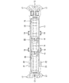
本発明の実施形態1を図1ないし図9によって説明する。本実施形態に係るレバー式コネクタは、ハウジング10及びレバー40を備え、ハウジング10が相手ハウジング80に嵌合可能とされている。なお、以下の説明において前後方向については、両ハウジング10、80の相互の嵌合面側を前方とする。
<Embodiment 1>
A first embodiment of the present invention will be described with reference to FIGS. The lever-type connector according to this embodiment includes a
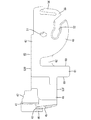
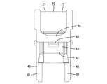
相手ハウジング80は合成樹脂製であって、図6に示すように、幅方向に長い角筒状のフード部81を有している。フード部81内には、図示しない複数の雄タブが突出して配置されている。フード部81の両側壁83(幅方向両端側の壁)の内面には、1対のロック受け部82が突出して形成されている。図6に示すように、両ロック受け部82は、爪状をなし、両側壁83の前端部の高さ方向略中央部に配置されている。
The
また、フード部81の上下両壁84U、84D(高さ方向両端側の壁)の内面には、それぞれ略円柱状のカムフォロア85が突出して形成されている。このうち、上側のカムフォロア85は、上壁84Uの幅方向中央を挟んだ両側に対をなして配置され、下側のカムフォロア85は、下壁84Dの幅方向中央を挟んだ両側に対をなして配置されている。つまり、各カムフォロア85は、高さ方向及び幅方向に関して対称に配置されている。また、フード部81の上下両壁84U、84Dの内面には、その4角寄りの位置に、それぞれ凹部86が形成されている。
Further, substantially
ハウジング10は合成樹脂製であって、図4及び図5に示すように、幅方向に長い角ボックス状のハウジング本体11を有している。ハウジング本体11は、幅方向両端側に位置する左右1対の短辺部12と、高さ方向両端側に位置する上下1対の長辺部13と、前端側に位置する前壁14とを有し、後方に開放されている。ハウジング本体11内には、複数のサブハウジング収容部15が幅方向に並列に形成され、各サブハウジング収容部15の間に、仕切部16が形成されている。各サブハウジング収容部15内には、後方から図示しないサブハウジングが挿入されるようになっている。各サブハウジングには雌端子金具が挿入され、両ハウジング10、80の正規嵌合時に、各雌端子金具が各雄タブと電気的に接続されるようになっている。雌端子金具は電線90の端末部に接続され、電線90はサブハウジング(ハウジング10)の後面から外部に引き出されている。
The
両長辺部13の前端部の幅方向両端側には、それぞれ凸部17が形成されている。両ハウジング10、80の正規嵌合時には、各凸部17が各凹部86内に嵌合するが、両ハウジング10、80の誤嵌合時には、各凸部17が各凹部86に嵌合せず、もって両ハウジング10、80の誤嵌合状態が検知されるようになっている。
両長辺部13の後端縁の幅方向中央部は、幅方向両端部よりも後方へ突出して配置され、この突出部分が、軸部19の一部が支持される支持部18とされている。軸部19は、支持部18の幅方向両側に対をなして配置され、その後端部が支持部18側に入り込んでいる。さらに、両長辺部13の前端部の幅方向一端側には、掛止部21が突出して形成されている。掛止部21は、両長辺部13の外面と平行な板片22を有している。
The central part in the width direction of the rear end edges of both
レバー40は合成樹脂製であって、図7に示すように、高さ方向に沿った連結板41と、連結板41の両端から幅方向に突出する1対の側板42とからなり、全体として門型をなしている。連結板41には、図8及び図9に示すように、撓み可能なロック部43が形成されている。ロック部43は、連結板41の前端部に撓み動作の支点となる基端部44を有し、そこから後方へ向けて片持ち状に延出する形態とされている。ロック部43の中間部には、ロック孔45が貫通して形成されている。
The
連結板41の後端部には、ロック部43の後端部(自由端部)の周りを包囲するアーチ状の保護部46が形成されている。また、連結板41の後端部には、後方へ突出するとともに、幅方向一端側へ向けて両側板42の後端縁に沿って階段状に下る操作部47が形成されている。
An arch-shaped
両側板42は、連結板41から離れた位置にあって円弧状の外周縁を有する作用部48と、作用部48と連結板41との間をつなぐ連繋部49とからなる。作用部48には、略円形の軸受孔51が貫通して形成されているとともに、所定方向に延出して外周縁に開口する無底のカム溝52が形成されている。
The both
連繋部49の後端縁には、操作部47を除く部分に、直線状のストレート縁53Rが形成され、連繋部49の前端縁には、後述する突片61を除く部分に、直線状のストレート縁53Fが形成されている。作用部48には、撓み可能な弾性片54が切り欠いて形成されている。弾性片54は、カム溝52の入り口近くに撓み動作の支点となる基端部55を有し、そこから作用部48の外周縁に沿って延出する形態とされている。図3に示すように、弾性片54の先端側には、第1突起56が外側に突出して形成され、弾性片54の基端側には、第2突起57が外側に突出して形成されている。
A straight
ここで、レバー40は、ハウジング10に対して後方から跨ぐようにして装着され、装着時には、軸受孔51に幅方向一側(掛止部21の存する側であって図示向かって右側)の軸部19が弾性的に嵌合して支持されるようになっている。そして、レバー40は、ストレート縁53Rがハウジング10の後端縁に対し交差する方向に傾斜して配置されて両側板42がハウジング10の後端縁よりも後方へ大きく突出する突出位置(図3を参照)と、ストレート縁53Rがハウジング10の後端縁とほぼ平行に配置されて両側板42がハウジング10の後端縁から小さく突出する退避位置(図2を参照)とに、軸部19を支点として回動可能とされている。突出位置では、弾性片54の第1突起56が掛止部21の板片22を弾性的に係止することで、レバー40の退避位置への回動操作が規制される。また、図1に示すように、突出位置では、カム溝52の入り口が前方に開放され、相手ハウジング80のフード部81内にハウジング10が浅く嵌合されることで、カム溝52の入り口に前方からカムフォロア85が挿入される。このとき、相手ハウジング80によって第1突起56と掛止部21との係止状態が解除され、さらに弾性片54が撓み変形させられて、レバー40の退避位置への回動操作が許容される。突出位置から退避位置へは、操作部47を後方から押圧することで両側板42の突出量を次第に減少させるようにする。この間、カム溝52の溝面にカムフォロア85が摺動することでレバー40と相手ハウジング80との間に倍力作用がはたらき、両ハウジング10、80が互いに低操作力で嵌合される。
Here, the
退避位置では、図2に示すように、弾性片54の第2突起57が張出片の板片22を弾性的に係止することで、レバー40の突出位置への回動操作が規制される。また、退避位置では、ロック部43のロック孔45にロック受け部82が弾性的に嵌り、レバー40がハウジング10に正規嵌合状態に保持される。このとき、カム溝52の奥端にカムフォロア85が到達するとともに、雌端子金具と雄タブとが互いに導通接続される。レバー40を突出位置に戻す際には、ロック部43の自由端部を外側から押圧して、ロック部43とロック受け部82との係止状態を解除させ、その状態でレバー40を突出位置へ持ち上げればよい。なお、レバー40に突出位置への操作力を付与することにより、第2突起57と掛止部21との係止状態は容易に解除される。また、保護部46によってロック部43への不用意な解除操作が阻止される。
In the retracted position, as shown in FIG. 2, the
ところで、相手ハウジング80内には、上記ハウジング10とは図示しない別のハウジングが嵌合可能となっている。この別のハウジングは、ハウジング10とは掛止部21の形成位置が幅方向で反対側となるものの、ハウジング10とその略後半部を共通構造とするものであって、上記軸部19とは幅方向で反対側の軸部19に、レバー40が支持可能となっている。この場合、レバー40の回動方向は、上記とは反対方向となり、レバー40のカム溝52は、上記カムフォロア85とは幅方向で反対側のカムフォロア85に係合可能となる。これにより、別のハウジングとハウジング10とで相手ハウジング80が共用されるとともに、ハウジング10の略後半部と別のハウジングの略後半部が同じ金型を用いて成形されることとなる。
By the way, another housing (not shown) can be fitted into the
さて、レバー40の側板42について詳述すると、両側板42の連繋部49の前端縁には、略矩形板状の突片61が前方に突出して形成されている。突片61は、作用部48よりも薄肉とされ、図8に示すように、その直線状の幅方向一側縁68が作用部48の外周縁と幅方向で離間しつつ対向して配置され、その直線状の幅方向他側縁69がストレート縁53Fと略直交して配置されている。両側板42の連繋部49の内面には、有底の凹所62が連繋部49の前端縁に開口して形成されている。
Now, the
突出位置では、図3に示すように、突片61の先端側の一角部が、ハウジング10の支持部18に外側から被さり、支持部18に前後方向で重なるように配置される。このとき、突片61の内側には、ハウジング10の後端面から引き出された電線90が収容され、該電線90が突片61の内面に当接可能に配置される。
At the protruding position, as shown in FIG. 3, the corner portion on the tip side of the protruding
また、突出位置では、突片61の幅方向一側縁、連繋部49の前端縁、作用部48の外周縁、及び支持部18の後端縁の間に、ループ状の第1空間部63が区画して形成される。上記凹所62は、第1空間部63の直後方に連続して形成されている。さらに、突片61の幅方向他側縁、連繋部49の前端縁、及びハウジング10の後端縁の間には、幅方向他側に開放される第2空間部64が区画して形成される。つまり、第1空間部63は、第2空間部64よりも軸部19寄りで、かつ、レバー40を支持しない幅方向他側の軸部19、及びカム溝52に進入しない幅方向他側のカムフォロア85と、レバー40の回動方向で対向する位置に配置される。
Further, at the projecting position, the loop-shaped
退避位置では、図2に示すように、突片61の先端縁がハウジング10の前端縁に沿いつつこの前端縁からやや後方に控えて配置される。また、退避位置では、レバー40を支持しない幅方向他側の軸部19が凹所62内に進入して逃がされるとともに、カム溝52に進入しない幅方向他側のカムフォロア85が第1空間部63内に進入して逃がされる。つまり、第1空間部63は、幅方向他側のカムフォロア85の逃がし空間となっている。このとき、幅方向他側のカムフォロア85は、突片61の幅方向一側縁68の基端側の近傍に位置するようになっている。
In the retracted position, as shown in FIG. 2, the tip edge of the projecting
以上説明したように本実施形態によれば、レバー40が突出位置にあるときに、突片61の先端部がハウジング10の後端縁と前後方向でラップして配置されるから、ハウジング10の後端面から引き出された電線90のはみ出しが突片61によって防止される。したがって、電線90が、両側板42の前端縁とハウジング10の後端縁との間に噛み込まれるのが防止される。また、突片61がハウジング10の後端縁に外側から被さることにより、突出位置における両側板42の内倒れが回避される。
As described above, according to the present embodiment, when the
また、退避位置では、第1空間部63に相手ハウジング80のカムフォロア85が進入するため、両側板42とカムフォロア85との干渉が回避される。これにより、相手ハウジング80にカムフォロア85が支障なく形成され、別のハウジングとハウジング10との間で相手ハウジング80を共用することが可能となる。さらに、退避位置では、突片61の先端がハウジング10の前端縁からやや後方に控えて配置されるから、突片61の先端に外部異物が干渉するのが回避される。
Further, at the retracted position, the
さらにまた、軸部19がハウジング10の後端縁において後方へ部分的に突出する支持部18に形成され、突出位置では、突片61の先端部が支持部18と前後方向に関してラップする位置に配置されるから、突片61の突出量をさほど長くしなくても、突片61の先端部をハウジング10とのラップ位置に至らすことができる。これにより、突片61の突出量を減じることが可能となり、退避位置において、突片61の先端がハウジング10の前端縁よりも前方に突き出るのがより確実に防止される。
Furthermore, the
<他の実施形態>
本発明は上記記述及び図面によって説明した実施形態に限定されるものではなく、例えば次のような実施形態も本発明の技術的範囲に含まれる。
(1)レバーが退避位置にあるときに、第1空間部に進入するものは、カムフォロア以外の任意で突起物で構成され得る。この場合、突起物は、相手ハウジングに形成されるものに限らず、ハウジングに形成されるものであってもよい。
(2)レバーは、全体として一枚板状の側板からなるものであってもよい。
(3)退避位置では、両側板の後端縁がハウジングの後端縁と同じ位置に配置されていてもよい。
(4)退避位置では、両側板の後端縁がハウジングの後端縁よりも前方に引っ込む位置に配置されていてもよい。
(5)退避位置では、突片の先端がハウジングの前端縁と同じ位置に配置されていてもよい。
<Other embodiments>
The present invention is not limited to the embodiments described with reference to the above description and drawings. For example, the following embodiments are also included in the technical scope of the present invention.
(1) When the lever is in the retracted position, the one that enters the first space portion can be constituted by any projection other than the cam follower. In this case, the protrusions are not limited to those formed on the mating housing, but may be formed on the housing.
(2) The lever may be composed of a single plate-like side plate as a whole.
(3) In the retracted position, the rear end edges of both side plates may be arranged at the same position as the rear end edge of the housing.
(4) In the retracted position, the rear end edges of the both side plates may be disposed at a position where the rear end edges of the both sides of the housing are retracted forward.
(5) In the retracted position, the tip of the projecting piece may be disposed at the same position as the front end edge of the housing.
10…ハウジング
18…支持部
19…軸部
40…レバー
51…軸受孔
52…カム溝
61…突片
63…第1空間部(軸部寄りの空間部)
64…第2空間部(空間部)
80…相手ハウジング
85…カムフォロア
90…電線
DESCRIPTION OF
64 ... 2nd space part (space part)
80 ...
Claims (4)
前記ハウジングの軸部に支持されつつ前記相手ハウジングに係合可能な側板を有し、前記側板が前記ハウジングの後端縁から大きく突出する突出位置と、前記側板が前記ハウジングの後端縁から小さく突出する、又は突出しない退避位置とに、前記軸部を中心として回動可能とされ、その回動操作によって前記相手ハウジングを引き込む倍力作用を発揮して、両ハウジングの嵌合動作を進めるレバーとを備えるレバー式コネクタであって、
前記側板の前端縁には、前方へ突出する形態であって、前記突出位置では、先端部が前記ハウジングの後端縁と前後方向に関してラップする突片が形成され、さらに、
前記突出位置では、前記突片の両側縁、前記側板の前端縁、及び前記ハウジングの後端縁との間に、空間部が開口して形成され、このうち、前記軸部寄りの空間部が、前記退避位置において、前記ハウジング又は前記相手ハウジングに形成された突起物が進入する逃がし空間となっていることを特徴とするレバー式コネクタ。 A housing that can be fitted into a mating housing and from which a wire is drawn out from the rear end surface;
A side plate that can be engaged with the mating housing while being supported by the shaft portion of the housing, and wherein the side plate protrudes greatly from the rear end edge of the housing; and the side plate is smaller than the rear end edge of the housing. A lever that is pivotable around the shaft portion to a retracted position that protrudes or does not protrude, and that exerts a boosting action that pulls in the mating housing by the rotation operation to advance the fitting operation of both housings A lever-type connector comprising:
The front end edge of the side plate is configured to protrude forward, and at the protruding position, a protruding piece whose front end portion wraps in the front-rear direction with the rear end edge of the housing is formed.
In the projecting position, a space portion is formed by opening between both side edges of the projecting piece, the front end edge of the side plate, and the rear end edge of the housing, and among these, the space portion near the shaft portion is formed. A lever-type connector characterized in that, in the retracted position, a relief space into which a protrusion formed on the housing or the mating housing enters is provided.
前記突起物が、前記カム溝に進入しないカムフォロアによって構成されている請求項1記載のレバー式コネクタ。 A cam groove is formed in the side plate, and a plurality of cam followers are formed in the mating housing. When the two housings are fitted, the cam groove selectively enters one of the cam followers, and the lever rotates. The cam follower is moved relative to the cam groove by a moving operation to exert the boosting action,
The lever type connector according to claim 1, wherein the protrusion is configured by a cam follower that does not enter the cam groove.
Priority Applications (4)
| Application Number | Priority Date | Filing Date | Title |
|---|---|---|---|
| JP2010061236A JP5407960B2 (en) | 2010-03-17 | 2010-03-17 | Lever type connector |
| DE102011012064A DE102011012064A1 (en) | 2010-03-17 | 2011-02-23 | A lever-type connector |
| CN2011100609247A CN102195205A (en) | 2010-03-17 | 2011-03-10 | Lever-type connector |
| US13/050,214 US8215979B2 (en) | 2010-03-17 | 2011-03-17 | Lever-type connector |
Applications Claiming Priority (1)
| Application Number | Priority Date | Filing Date | Title |
|---|---|---|---|
| JP2010061236A JP5407960B2 (en) | 2010-03-17 | 2010-03-17 | Lever type connector |
Publications (2)
| Publication Number | Publication Date |
|---|---|
| JP2011198517A JP2011198517A (en) | 2011-10-06 |
| JP5407960B2 true JP5407960B2 (en) | 2014-02-05 |
Family
ID=44602809
Family Applications (1)
| Application Number | Title | Priority Date | Filing Date |
|---|---|---|---|
| JP2010061236A Expired - Fee Related JP5407960B2 (en) | 2010-03-17 | 2010-03-17 | Lever type connector |
Country Status (4)
| Country | Link |
|---|---|
| US (1) | US8215979B2 (en) |
| JP (1) | JP5407960B2 (en) |
| CN (1) | CN102195205A (en) |
| DE (1) | DE102011012064A1 (en) |
Families Citing this family (12)
| Publication number | Priority date | Publication date | Assignee | Title |
|---|---|---|---|---|
| EP2506369A1 (en) * | 2011-04-01 | 2012-10-03 | Eaton Industries GmbH | Assembly for producing and separating a connection between a connector and a female connector |
| JP5798897B2 (en) * | 2011-11-24 | 2015-10-21 | 矢崎総業株式会社 | Lever fitting type connector |
| KR101503507B1 (en) * | 2014-04-09 | 2015-03-18 | 주식회사 경신 | Connector for vehicle |
| JP6159310B2 (en) * | 2014-11-17 | 2017-07-05 | 矢崎総業株式会社 | Lever type connector |
| JP6572188B2 (en) * | 2016-09-07 | 2019-09-04 | 矢崎総業株式会社 | Lever type connector |
| CN108666831A (en) * | 2017-03-31 | 2018-10-16 | 胡正宇 | A kind of plug-in connector for electric connection equipped with automatic locking mechanism |
| JP6210262B1 (en) * | 2017-05-15 | 2017-10-11 | 住友電装株式会社 | Lever type connector |
| JP6826758B2 (en) * | 2017-07-18 | 2021-02-10 | 住友電装株式会社 | Lever type connector |
| US9948030B1 (en) | 2017-09-15 | 2018-04-17 | Phoenix Contact Development and Manufacturing, Inc. | Lever-type electrical connector body and related electrical connector assembly |
| CN108075294B (en) * | 2017-09-29 | 2024-03-26 | 安波福中央电气(上海)有限公司 | High-energy electric connector with rotary driving rod |
| JP6944410B2 (en) * | 2018-06-06 | 2021-10-06 | 住友電装株式会社 | Lever type connector |
| JP7604171B2 (en) * | 2020-10-26 | 2024-12-23 | モレックス エルエルシー | Connector Assembly |
Family Cites Families (26)
| Publication number | Priority date | Publication date | Assignee | Title |
|---|---|---|---|---|
| FR2717627B1 (en) * | 1994-03-21 | 1996-04-26 | Cinch Connecteurs Sa | Device for coupling two housing elements of an electrical connector. |
| EP1079473B1 (en) * | 1995-10-24 | 2003-03-12 | Sumitomo Wiring Systems, Ltd. | Lever type connector |
| JP3422925B2 (en) * | 1998-03-30 | 2003-07-07 | 矢崎総業株式会社 | Electrical connector |
| JP3538750B2 (en) * | 1999-08-02 | 2004-06-14 | 住友電装株式会社 | Lever type connector |
| JP2001076812A (en) * | 1999-09-09 | 2001-03-23 | Sumitomo Wiring Syst Ltd | Lever connector |
| US6361356B1 (en) * | 2000-10-03 | 2002-03-26 | Delphi Technologies, Inc. | Electrical connector position assurance device |
| JP3961228B2 (en) * | 2001-03-28 | 2007-08-22 | 矢崎総業株式会社 | Lever fitting type connector |
| JP2003036925A (en) * | 2001-07-19 | 2003-02-07 | Sumitomo Wiring Syst Ltd | Lever type connector |
| US6558176B1 (en) * | 2002-03-07 | 2003-05-06 | Tyco Electronics Corp. | Mate assist assembly for connecting electrical contacts |
| US6899554B1 (en) * | 2004-04-19 | 2005-05-31 | Jst Corporation | Dual action mechanical assisted connector |
| JP4475178B2 (en) * | 2005-06-16 | 2010-06-09 | 住友電装株式会社 | Lever type connector |
| JP4598681B2 (en) * | 2006-01-17 | 2010-12-15 | 矢崎総業株式会社 | Lever fitting type connector |
| US7396240B2 (en) * | 2006-04-05 | 2008-07-08 | J.S.T. Corporation | Electrical connector with a locking mechanism |
| JP4904093B2 (en) * | 2006-06-20 | 2012-03-28 | 矢崎総業株式会社 | connector |
| JP2008027691A (en) * | 2006-07-20 | 2008-02-07 | Yazaki Corp | Lever manufacturing method of lever fitting type connector |
| JP4248001B2 (en) * | 2006-10-19 | 2009-04-02 | 古河電気工業株式会社 | Lever connector |
| JP5029872B2 (en) * | 2006-12-19 | 2012-09-19 | 住友電装株式会社 | Lever type connector |
| JP4494443B2 (en) * | 2007-08-10 | 2010-06-30 | タイコエレクトロニクスジャパン合同会社 | Lever type connector |
| JP4963285B2 (en) * | 2007-10-05 | 2012-06-27 | 矢崎総業株式会社 | Lever fitting type connector |
| JP2009158430A (en) * | 2007-12-28 | 2009-07-16 | Sumitomo Wiring Syst Ltd | Lever-type connector |
| JP4989502B2 (en) * | 2008-02-08 | 2012-08-01 | 矢崎総業株式会社 | Lever fitting type connector |
| JP4468465B2 (en) * | 2008-03-28 | 2010-05-26 | タイコエレクトロニクスジャパン合同会社 | Lever type connector |
| JP2009259442A (en) * | 2008-04-14 | 2009-11-05 | Molex Inc | Connector |
| US7686631B1 (en) * | 2008-12-12 | 2010-03-30 | J.S.T. Corporation | Electrical connector with a latch mechanism |
| JP5233957B2 (en) * | 2009-10-29 | 2013-07-10 | 住友電装株式会社 | connector |
| JP5343902B2 (en) * | 2010-03-17 | 2013-11-13 | 住友電装株式会社 | connector |
-
2010
- 2010-03-17 JP JP2010061236A patent/JP5407960B2/en not_active Expired - Fee Related
-
2011
- 2011-02-23 DE DE102011012064A patent/DE102011012064A1/en not_active Ceased
- 2011-03-10 CN CN2011100609247A patent/CN102195205A/en active Pending
- 2011-03-17 US US13/050,214 patent/US8215979B2/en active Active
Also Published As
| Publication number | Publication date |
|---|---|
| JP2011198517A (en) | 2011-10-06 |
| CN102195205A (en) | 2011-09-21 |
| DE102011012064A1 (en) | 2011-11-24 |
| US8215979B2 (en) | 2012-07-10 |
| US20110230080A1 (en) | 2011-09-22 |
Similar Documents
| Publication | Publication Date | Title |
|---|---|---|
| JP5407960B2 (en) | Lever type connector | |
| JP6424190B2 (en) | Lever type connector | |
| US8662906B2 (en) | Plug-and-socket connector with a blocking element | |
| JP5811429B2 (en) | Lever type connector | |
| JP5407959B2 (en) | connector | |
| JP4317973B2 (en) | connector | |
| JP5343902B2 (en) | connector | |
| JP2003317853A (en) | Connector with lever | |
| JP2012109174A (en) | Lever-type connector | |
| JP2008130244A (en) | Connector | |
| JP4497038B2 (en) | Lever type connector | |
| JP6564750B2 (en) | Lever type connector | |
| JP2016051633A (en) | Lever type connector | |
| JP4904094B2 (en) | connector | |
| JP4963285B2 (en) | Lever fitting type connector | |
| WO2013005658A1 (en) | Lever-type connector | |
| JP6611367B2 (en) | Lever type connector | |
| JP5985801B2 (en) | Lever type connector | |
| JP5846103B2 (en) | Lever type connector | |
| JP2012146445A (en) | Connector with lever | |
| JP5035361B2 (en) | Lever type connector | |
| JP7759553B2 (en) | connector | |
| JP2012252973A (en) | Connector | |
| JP5596361B2 (en) | Waterproof connector | |
| JP2008235059A (en) | Connector |
Legal Events
| Date | Code | Title | Description |
|---|---|---|---|
| A621 | Written request for application examination |
Free format text: JAPANESE INTERMEDIATE CODE: A621 Effective date: 20120829 |
|
| A977 | Report on retrieval |
Free format text: JAPANESE INTERMEDIATE CODE: A971007 Effective date: 20130712 |
|
| A131 | Notification of reasons for refusal |
Free format text: JAPANESE INTERMEDIATE CODE: A131 Effective date: 20130730 |
|
| A521 | Request for written amendment filed |
Free format text: JAPANESE INTERMEDIATE CODE: A523 Effective date: 20130917 |
|
| TRDD | Decision of grant or rejection written | ||
| A01 | Written decision to grant a patent or to grant a registration (utility model) |
Free format text: JAPANESE INTERMEDIATE CODE: A01 Effective date: 20131008 |
|
| A61 | First payment of annual fees (during grant procedure) |
Free format text: JAPANESE INTERMEDIATE CODE: A61 Effective date: 20131021 |
|
| R150 | Certificate of patent or registration of utility model |
Ref document number: 5407960 Country of ref document: JP Free format text: JAPANESE INTERMEDIATE CODE: R150 |
|
| LAPS | Cancellation because of no payment of annual fees |