JP5407534B2 - Leg shield front rack structure - Google Patents
Leg shield front rack structure Download PDFInfo
- Publication number
- JP5407534B2 JP5407534B2 JP2009113843A JP2009113843A JP5407534B2 JP 5407534 B2 JP5407534 B2 JP 5407534B2 JP 2009113843 A JP2009113843 A JP 2009113843A JP 2009113843 A JP2009113843 A JP 2009113843A JP 5407534 B2 JP5407534 B2 JP 5407534B2
- Authority
- JP
- Japan
- Prior art keywords
- leg shield
- front rack
- shield cover
- rib portions
- vehicle
- Prior art date
- Legal status (The legal status is an assumption and is not a legal conclusion. Google has not performed a legal analysis and makes no representation as to the accuracy of the status listed.)
- Expired - Fee Related
Links
Images


Landscapes
- Automatic Cycles, And Cycles In General (AREA)
Description
本発明は、レッグシールドのフロントラック構造に関するものである。 The present invention relates to a front rack structure of a leg shield.
スクータ型自動二輪車には、着座シートに着座したライダーの足の前方を覆うレッグシールドが形成されている。そして、スクータ型自動二輪車のタイプによっては、このレッグシールドの後部にフロントラックが取り付けられ、レッグシールドの後部とフロントラックとの間の空間により、上方に開口する収容スペースが形成される。例えば、特許文献1に開示されたスクータ型自動二輪車は、レッグシールドの上縁部分が開口をなす収容ボックスが形成されている。このように形成された収容スペースは、着座したライダーの足の直前に位置している。したがって、ライダーが着座した状態で収容スペースに手を伸ばすことで、例えば、収容スペース内の収容物を取り出したり、収容物を入れたりすることができるために、スクータ型自動二輪車の利便性を向上させている。そして、収容スペースは、なるだけ多くのものが収容できるように大きく形成されている。 The scooter type motorcycle is formed with a leg shield that covers the front of the rider's foot seated on the seat. Depending on the type of the scooter type motorcycle, a front rack is attached to the rear part of the leg shield, and a space between the rear part of the leg shield and the front rack forms an accommodation space that opens upward. For example, in a scooter type motorcycle disclosed in Patent Document 1, an accommodation box is formed in which an upper edge portion of a leg shield forms an opening. The accommodation space formed in this way is located immediately in front of the rider's feet. Therefore, the convenience of the scooter type motorcycle can be improved by reaching out to the storage space while the rider is seated so that, for example, the stored items in the storage space can be taken out and inserted. I am letting. The storage space is formed large so that as many as possible can be stored.
一方、例えば、ライダーが有料道路に乗るために有料道路料金を支払おうとする場合、スクータ型自動二輪車を停止させた状態で衣服や鞄等から財布を取り出し、その後財布から料金に相当するコイン(硬貨)等を取り出さなければならず、非常に煩わしいものである。
この場合、予め上述したフロントラックにより形成された収容スペース内に、コインを入れておくことも考えられるが、収容スペースは、コインに比べて大きく、さらに走行しているうちにコインが収容スペース内を移動してしまうために、ライダーがコインを取り出そうとするときに見つけるのが容易ではないという問題がある。
On the other hand, for example, when a rider wants to pay a toll road to get on a toll road, the purse is taken out from clothes or bags with the scooter type motorcycle stopped, and then coins corresponding to the toll (coin coins) ) Etc. must be taken out, which is very troublesome.
In this case, it is conceivable to put coins in the storage space formed by the front rack described above in advance, but the storage space is larger than the coins, and the coins are stored in the storage space while traveling. , It is not easy to find when a rider tries to take out a coin.
本発明は、上述したような問題点に鑑みてなされたものであり、フロントラックにより形成された収容部内に、コインを収容することができるようにすることを目的とする。 The present invention has been made in view of the above-described problems, and an object thereof is to allow coins to be accommodated in an accommodation portion formed by a front rack.
本発明に係るレッグシールドのフロントラック構造は、レッグシールドと、前記レッグシールドの裏面をなすレッグシールドカバーに取り付けられて、前記レッグシールドカバーとの間の空間により袋状の収容部を形成するフロントラックとを備え、前記レッグシールドカバーの左右方向における中央部には、隆起部が上下方向に沿って形成され、前記フロントラックの内面であって、その左右方向における中央部で前記レッグシールドカバーに接する下部に、前記隆起部に向かって延伸し、先端が前記隆起部に当接或いは近接する少なくとも2枚の平行なリブ部が一体に形成されており、これらリブ部間をコイン保持部としたことを特徴とする。
また、前記フロントラックの内面の左右方向における中央部には、前記隆起部に取り付けられる支持部が設けられ、前記少なくとも2枚の平行なリブ部は、前記支持部の左右少なくとも何れか一方に形成されていることを特徴とする。
A front rack structure of a leg shield according to the present invention is a front shield that is attached to a leg shield and a leg shield cover that forms the back surface of the leg shield, and forms a bag-like housing portion by a space between the leg shield cover. And a ridge is formed along the vertical direction at the center portion in the left-right direction of the leg shield cover, and is an inner surface of the front rack, and the leg shield cover at the center portion in the left-right direction. At least two parallel rib portions that extend toward the bulging portion and that have a tip abutting against or proximate to the bulging portion are integrally formed in a lower portion in contact with each other, and a gap between the rib portions is used as a coin holding portion. It is characterized by that.
Also, the central portion in the lateral direction of the inner surface of the front rack, the obtained support portion attached is provided in the raised portion, wherein at least two parallel ribs are left at least either one of said support portions It is formed.
本発明によれば、前記フロントラックの内面に、前記レッグシールドカバーに向かって延伸する少なくとも2枚の平行なリブ部が形成されており、これらリブ部間をコイン保持部としたことから、コイン保持部にコインを保持することができるので、フロントラックにより形成される収容部の利便性を向上させることができる。また、フロントラックにリブ部を形成するだけでよいので、簡易な金型構造でコイン保持部を形成することができる。さらに、レッグシールドカバーには、リブ部が形成されていないので、フロントラックを設けないタイプにするために、フロントラックを取り外したときでも、見栄えを損なうことがない。
また、本発明によれば、例えば前記レッグシールドカバーの左右方向における中央部には、隆起部が上下方向に沿って形成され、前記少なくとも2枚の平行なリブ部は、前記隆起部に向かって延伸していることから、コイン保持部をライダーの手元近くに形成することができるので、フロントラックにより形成される収容部の利便性をさらに向上させることができる。
また、本発明によれば、前記フロントラックの内面の左右方向における中央部には、前記隆起部に取り付けられる支持部が設けられ、前記少なくとも2枚の平行なリブ部は、前記支持部の左右少なくとも何れか一方に形成されていることから、支持部に影響を与えることがなく、さらに、コイン保持部が形成されている左右何れかに対応した、ライダーの手によりコインが取り出しやすくなる。
According to the present invention, at least two parallel rib portions extending toward the leg shield cover are formed on the inner surface of the front rack, and the coin holding portion is formed between the rib portions. Since the coin can be held in the holding portion, the convenience of the storage portion formed by the front rack can be improved. Further, since it is only necessary to form the rib portion on the front rack, the coin holding portion can be formed with a simple mold structure. Further, since the rib portion is not formed on the leg shield cover, the appearance does not deteriorate even when the front rack is removed in order to make the type without the front rack.
Further, according to the present invention, for example, a bulge is formed along the vertical direction at the center in the left-right direction of the leg shield cover, and the at least two parallel ribs are directed toward the bulge. Since it is extended, the coin holding part can be formed near the rider's hand, so that the convenience of the storage part formed by the front rack can be further improved.
According to the present invention, the central portion of the inner surface of the front rack in the left-right direction is provided with a support portion attached to the raised portion, and the at least two parallel rib portions are provided on the left and right sides of the support portion. Since it is formed on at least one of the sides, the support portion is not affected, and the coin can be easily taken out by the rider's hand corresponding to the left or right side where the coin holding portion is formed.
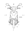
以下、本発明を実施するための形態を説明する。図1、図2はそれぞれ、本発明を適用したスクータ型自動二輪車(以下、車両)1の側面図及び正面図である。先ず、図1、図2を用いて、車両1の概略構成について説明する。なお、これらの図を含む、以下の説明で用いる図においては、必要に応じて車両の前方を矢印Frにより、車両の後方を矢印Rrにより示し、また、車両の側方右側を矢印Rにより、車両の側方左側を矢印Lにより示す。 Hereinafter, modes for carrying out the present invention will be described. 1 and 2 are a side view and a front view of a scooter type motorcycle (hereinafter referred to as a vehicle) 1 to which the present invention is applied, respectively. First, a schematic configuration of the vehicle 1 will be described with reference to FIGS. 1 and 2. In the drawings used in the following description including these figures, the front of the vehicle is indicated by an arrow Fr, the rear of the vehicle is indicated by an arrow Rr, and the lateral right side of the vehicle is indicated by an arrow R as necessary. The left side of the vehicle is indicated by an arrow L.
車両1は、鋼製或いはアルミニウム合金製でなる複数の車体フレームにより車体骨格を形成し、車体フレームに対する各種部品の艤装を経て構成される。車体フレームの一部であるダウンチューブパイプ2は、その前端をステアリングヘッドパイプ3と結合して、ステアリングヘッドパイプ3から略下方向に向けて延出し、その後湾曲して略後方に延出する。ダウンチューブパイプ2の後部側には、車体フレームの一部である左右一対のリヤフレーム4が結合し、それぞれが後上方に傾斜して延出する。
The vehicle 1 is configured by forming a vehicle body skeleton by a plurality of vehicle body frames made of steel or aluminum alloy and mounting various parts on the vehicle body frame. The
ステアリングヘッドパイプ3は、フロントフォーク5を回動可能に支持しており、フロントフォーク5の上端にはハンドルバーが固定されるとともに、下端側には前輪7が回動可能に支持される。また、前輪7には一体回転するブレーキディスク8が設置される。
The steering head pipe 3 supports a
ダウンチューブパイプ2の後端には、エンジンブラケット9が形成され、エンジンブラケット9はステー10を介してスイングユニット型エンジン11を支持し、ステー10の支持部を中心にスイングユニット型エンジン11を上下方向に向けて揺動可能とする。スイングユニット型エンジン11は、シリンダアッセンブリ12、クランクケース13、及び変速機を内包する変速ユニット14をユニット化したものであり、後輪15を支持するとともに、リヤフレーム4との間でショックアブソーバ16を装架することでスイングアームとしての機能も有するものである。
An
より詳しく説明すると、ダウンチューブパイプ2の後端にはスイングユニット型エンジン11を支持するためのエンジンブラケット9がダウンチューブパイプ2と一体的に形成されるか、或いは、ダウンチューブパイプ2の後端に強固に固定されて車両後方に延出する。エンジンブラケット9は、さらにステー10を固定して、このステー10においてスイングユニット型エンジン11を上下方向に向けて揺動可能に支持する。スイングユニット型エンジン11のクランクケース13にはスイングピボット部17が一体的に形成されており、このスイングピボット部17がステー10に軸支される。そして、スイングユニット型エンジン11において車両後方に位置する変速ユニット14は、その車幅方向内側の側面において後輪15を回動可能に支持し、その上面においてショックアブソーバ16を支持する。この構成により、スイングユニット型エンジン11はスイングアームとしての機能を有することになる。
More specifically, an
スイングユニット型エンジン11が車両1に搭載された状態では、車両前側からシリンダアッセンブリ12、クランクケース13、変速ユニット14の順で並ぶことになる。シリンダアッセンブリ12内には単気筒の空冷式エンジンが含まれ、シリンダ軸線が車両前後方向に沿って略水平となる状態で搭載される。そして、クランクケース13に含まれるクランク軸からの動力は車両前後方向に沿って略水平に張架されるVベルト等の伝達部材で変速ユニット14に含まれるドリブンスプロケットに伝達される。このような構成により、スイングユニット型エンジン11は側面視で横長形状となり、長手方向が車両前後方向に沿って略水平となる状態で車両1に搭載され、車両高さの抑制或いは低重心化を図るレイアウト構成となっている。
When the swing
また、スイングユニット型エンジン11の上方には、ライダーが着座するための着座シート18が設置され、ダウンチューブパイプ2の上方にはライダーが着座した状態で足を載せるステップボード19が不図示のステップフレームに支持される。なお、ステップボード19は車両外観を構成するレッグシールドカバー20と一体的に形成される。レッグシールドカバー20の後方には、フロントラック21が取り付けられ、レッグシールドカバー20とフロントラック21とでフロントラック構造30が形成され、収容部22としての空間が形成される。また、スイングユニット型エンジン11と着座シート18との間には、着座シート18により開閉される所謂ヘルメットボックスである物品収納スペースが形成される。
Also, a
車両外観としては、各種車体カバーが車体フレーム等の適所に支持されて被着される。ハンドルカバー23は、ハンドル6に接続される不図示のハンドルバーを覆っている。レッグシールド24は、レッグシールド本体25とレッグシールドカバー20とからなり、ウィンカ等が実装され、車両前面側を覆って、上述のステップボード19と一体的に連なる。リヤフレームカバー26は、ウィンカやブレーキランプが実装され、車両側方および後方を覆っている。なお、リヤフレームカバー26の内側に物品収納スペースが形成されることになる。また、リヤフレームカバー26の後方には、ウィンカやブレーキランプを後方から覆うリヤコンビランプ27が取り付けられている。さらに、リヤコンビランプ27の下方には、後輪15の上方を覆うリヤフェンダ28が設けられている。
As a vehicle exterior, various vehicle body covers are supported and attached to appropriate positions such as a vehicle body frame. The
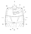
次に、本実施形態に係るフロントラック構造の詳細について図1〜図6を参照して説明する。ここで、図3は、フロントラック構造30を図1に示す矢視A方向から見た正面図である。また、図4は、フロントラック構造30を図3に示す矢視B方向から見た平面図である。図5は、フロントラック構造30を斜め上方から見た斜視図である。また、図6は、フロントラック21を収容部22内から見た斜視図である。
本実施形態に係るフロントラック構造30は、レッグシールド24の裏面を構成するレッグシールドカバー20と、このレッグシールドカバー20に取り付けられるフロントラック21とを含んで構成されている。
Next, details of the front rack structure according to the present embodiment will be described with reference to FIGS. Here, FIG. 3 is a front view of the
The
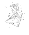
まず、レッグシールドカバー20は、レッグシールド24の表面を構成するレッグシールド本体25に対して裏側から覆うように取り付けることで、全体としてレッグシールド24を構成する。レッグシールドカバー20は、図3に示すように上方の左右端部および下方の左右端部それぞれに形成された係止部40a〜40dを介して、レッグシールド本体25に取り付けられる。さらに、レッグシールドカバー20は、図3に示すように上方であって左右方向における中央に形成された係止部41a、bを介してステアリングヘッドパイプ3に固定される。レッグシールド本体25とレッグシールドカバー20との間で形成される空間、すなわちレッグシールド24内は、ステアリングヘッドパイプ3、ダウンチューブパイプ2の一部、及びフロントフォーク5の一部等を覆っている。
First, the
また、レッグシールドカバー20の左右方向における中央部には、後方に向かって膨出する隆起部43が上下方向に沿って形成されている。隆起部43は、ステアリングヘッドパイプ3、およびダウンチューブパイプ2との干渉を防止するため、ステアリングヘッドパイプ3、およびダウンチューブパイプ2に沿うように隆起している。したがって、隆起部43は、図1に示すようにステアリングヘッドパイプ3を覆っている上側では、下方向に向かうに従って前方に傾斜し、ダウンチューブパイプ2を覆っている下側では、下方向に向かうに従って後方に傾斜する。また、レッグシールドカバー20の隆起部43の右側には、図3、4に示すように図示しないメインキーユニットが露出される開口部44が形成される。上述した形状のレッグシールドカバー20は、金型を用いて樹脂等により一体で射出成形される。
In addition, a bulging
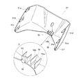
次に、フロントラック21は、レッグシールドカバー20に対して着座シート18側から取り付けることで、レッグシールドカバー20とフロントラック21との間の空間により、上方向に開口する袋状の収容部22が形成される。このフロントラック21は、レッグシールドカバー20の左右幅と略同一幅で形成されるとともに、着座シート18側から見て意匠面となる面が後方に緩やかに膨らむ略湾曲状に形成される。さらに、フロントラック21の左右端部であって、レッグシールドカバー20に接する部分には、図6に示すようにレッグシールド本体25に対する取付部51a〜51fが形成されている。また、フロントラック21の左右方向における中央部であって、レッグシールドカバー20に接する下部には、図6に示すようにレッグシールドカバー20側に突出する凸状の支持部52が形成されている。支持部52は、図6に示す拡大部Cに示すようにコ字状の取付台53に対して一体で形成されている。支持部52は、レッグシールドカバー20に穿設された図示しない支持孔に対して嵌入されることで、フロントラック21がレッグシールドカバー20に対して位置決めされる。
Next, the
さらに、フロントラック21には、支持部52から左側に離間した位置に、2枚の平行なリブ部54a、54bがレッグシールドカバー20側に延伸するように形成されている。フロントラック21をレッグシールドカバー20に取り付けた場合、この平行なリブ部54a、54bは、レッグシールドカバー20の隆起部43に当接、或いは近接する。そして、これら平行なリブ部54a、54b間は、コインを立てた状態で保持することができるコイン保持部55として形成される。コイン保持部55は、図6の破線で示すコインを立てた状態にしておくことができる。なお、コインを取り出しやすくするために、2枚の平行なリブ部54a、54bの高さは、コインを立てたときにコインの上部が表出する程度であることが好ましい。また、コイン保持部55の幅は、複数のコインを収容することができる程度の幅を有している。このような形状のフロントラック21は、金型を用いて樹脂等により一体で射出成形される。
Further, two
このように、本実施形態のフロントラック構造30では、平行なリブ部54a、54b間に形成されたコイン保持部55により予めコインを差し込んでおくことで、ライダーは、必要なときにコインを直ぐに取り出すことができるので、収容部22の利便性を向上させることができる。
また、本実施形態のコイン保持部55を形成する平行なリブ部54a、54bは、フロントラック21に一体で、レッグシールドカバー20に向かって延伸している。したがって、平行なリブ部54a、54bは、フロントラック21を成形する金型を彫り方向に切削するだけの比較的簡易な加工により形成することができる。
As described above, in the
Further, the
また、コイン保持部55を形成する平行なリブ部54a、54bは、フロントラック21にのみに形成され、レッグシールドカバー20には形成されていない。したがって、オプションとしてのフロントラック21を取り外して、フロントラック構造30を有しないタイプにしたときであっても、レッグシールドカバー20には平行なリブ部54a、54bは形成されていないので、レッグシールドカバー20の見栄えを損なうことがない。
また、コイン保持部55を形成する平行なリブ部54a、54bは、レッグシールドカバー20の隆起部43に向かって延伸させている。したがって、コイン保持部55は、形成される位置が収容部22内における後方となる。この場合、コイン保持部55は、ライダーが着座シート18に着座したときにライダーのより近い位置、すなわち手元近くに形成されるので、コインを取り出しやすく、収容部22の利便性をさらに向上させることができる。
Further, the
Further, the
また、コイン保持部55を形成する平行なリブ部54a、54bは、フロントラック21の内面の左右方向における中央部に設けられた支持部52から左側に離間して形成されている。したがって、平行なリブ部54a、54bが、支持部52が有するレッグシールドカバー20の位置決めという機能を阻害することなく、さらにコイン保持部55が形成されている左側に対応して、ライダーの左手でコインを取り出しやすくなる。
また、フロントラック21に平行なリブ部54a、54bを形成することで、フロントラック21自体の剛性を高めることができる。
Further, the
Further, by forming the
なお、本実施形態では、リブ部54a、54bは、支持部52から左側に離間した位置に形成されている場合についてのみ説明したが、この場合に限られず、右側であってもよい。さらに、支持部52の機能を他に代替できるのであれば、左右方向における中央部に設けてもよい。
また、2枚以上の平行なリブ部54a、54bを設け、複数のコイン保持部55を形成し、コインの種類別に保持できるようにしてもよい。
また、本実施形態のコイン保持部55は、スクータ型自動二輪車を取り上げて説明したが、この場合に限られない。例えば、電動車椅子等のレッグシールドを有する他の車両にも適用することができる。
In the present embodiment, the
Further, two or more
Moreover, although the coin holding |
1:車両 20:レッグシールドカバー 21:フロントラック 22:収容部
24:レッグシールド 43:隆起部 52:支持部 54a、54b:リブ部
55:コイン保持部
1: Vehicle 20: Leg shield cover 21: Front rack 22: Storage part 24: Leg shield 43: Raised part 52:
Claims (2)
前記レッグシールドの裏面をなすレッグシールドカバーに取り付けられて、前記レッグシールドカバーとの間の空間により袋状の収容部を形成するフロントラックとを備え、
前記レッグシールドカバーの左右方向における中央部には、隆起部が上下方向に沿って形成され、
前記フロントラックの内面であって、その左右方向における中央部で前記レッグシールドカバーに接する下部に、前記隆起部に向かって延伸し、先端が前記隆起部に当接或いは近接する少なくとも2枚の平行なリブ部が一体に形成されており、これらリブ部間をコイン保持部とした
ことを特徴とするレッグシールドのフロントラック構造。 Leg shield,
A front rack that is attached to a leg shield cover that forms the back surface of the leg shield and forms a bag-like housing portion by a space between the leg shield cover and
In the central portion in the left-right direction of the leg shield cover, a raised portion is formed along the vertical direction,
At least two parallel inner surfaces of the front rack that extend toward the raised portion at a lower portion in contact with the leg shield cover at a central portion in the left-right direction, and that have a tip abutting on or close to the raised portion. A front rack structure of a leg shield, in which a plurality of rib portions are formed integrally and a coin holding portion is formed between the rib portions.
前記少なくとも2枚の平行なリブ部は、前記支持部の左右少なくとも何れか一方に形成されている
ことを特徴とする請求項1に記載のレッグシールドのフロントラック構造。 In the central part in the left-right direction of the inner surface of the front rack, a support part attached to the raised part is provided,
The front rack structure of a leg shield according to claim 1 , wherein the at least two parallel rib portions are formed on at least one of the left and right sides of the support portion.
Priority Applications (1)
| Application Number | Priority Date | Filing Date | Title |
|---|---|---|---|
| JP2009113843A JP5407534B2 (en) | 2009-05-08 | 2009-05-08 | Leg shield front rack structure |
Applications Claiming Priority (1)
| Application Number | Priority Date | Filing Date | Title |
|---|---|---|---|
| JP2009113843A JP5407534B2 (en) | 2009-05-08 | 2009-05-08 | Leg shield front rack structure |
Publications (2)
| Publication Number | Publication Date |
|---|---|
| JP2010260481A JP2010260481A (en) | 2010-11-18 |
| JP5407534B2 true JP5407534B2 (en) | 2014-02-05 |
Family
ID=43358934
Family Applications (1)
| Application Number | Title | Priority Date | Filing Date |
|---|---|---|---|
| JP2009113843A Expired - Fee Related JP5407534B2 (en) | 2009-05-08 | 2009-05-08 | Leg shield front rack structure |
Country Status (1)
| Country | Link |
|---|---|
| JP (1) | JP5407534B2 (en) |
Family Cites Families (5)
| Publication number | Priority date | Publication date | Assignee | Title |
|---|---|---|---|---|
| JPS4887737U (en) * | 1972-01-26 | 1973-10-23 | ||
| JPS57130780U (en) * | 1981-02-09 | 1982-08-14 | ||
| JPS5865897U (en) * | 1981-10-28 | 1983-05-04 | トヨタ自動車株式会社 | vehicle ashtray |
| JP3484919B2 (en) * | 1997-04-25 | 2004-01-06 | スズキ株式会社 | Luggage rack mounting structure for scooter type vehicle |
| JP4188363B2 (en) * | 2005-11-28 | 2008-11-26 | 本田技研工業株式会社 | Scooter type article storage structure |
-
2009
- 2009-05-08 JP JP2009113843A patent/JP5407534B2/en not_active Expired - Fee Related
Also Published As
| Publication number | Publication date |
|---|---|
| JP2010260481A (en) | 2010-11-18 |
Similar Documents
| Publication | Publication Date | Title |
|---|---|---|
| EP2128007B1 (en) | Motorcycle | |
| JP4377954B1 (en) | Saddle riding vehicle | |
| JP4567083B2 (en) | Saddle riding vehicle | |
| JP5063298B2 (en) | Vehicle article storage structure | |
| JP5806643B2 (en) | Body cover structure for saddle-ride type vehicles | |
| EP2221220B1 (en) | Motorcycle | |
| JP2000118469A (en) | Body frame structure of scooter type motorcycle | |
| JP5407534B2 (en) | Leg shield front rack structure | |
| JP4684793B2 (en) | Vehicle front cover structure | |
| JP6133338B2 (en) | Front structure of motorcycle | |
| JP3838015B2 (en) | Scooter type motorcycle | |
| JP6861744B2 (en) | Guard member | |
| JP3743442B2 (en) | Scooter type motorcycle | |
| JP6759268B2 (en) | Saddle-type vehicle meter peripheral structure | |
| JP7177757B2 (en) | Straddle-type vehicle step structure | |
| JP7513933B1 (en) | Saddle-type vehicle | |
| JP4689399B2 (en) | Leg shield storage room structure | |
| JP4425962B2 (en) | Motorcycle | |
| JP4624206B2 (en) | License plate support structure | |
| JP5802038B2 (en) | Saddle riding | |
| JP5800649B2 (en) | Body frame structure of saddle riding type vehicle | |
| JP6281431B2 (en) | Motorcycle | |
| JP2010155578A (en) | Cover device of motorcycle | |
| JP4525234B2 (en) | Anti-theft holding device for scooter type motorcycle | |
| JP4825908B2 (en) | Saddle riding vehicle |
Legal Events
| Date | Code | Title | Description |
|---|---|---|---|
| A621 | Written request for application examination |
Free format text: JAPANESE INTERMEDIATE CODE: A621 Effective date: 20111228 |
|
| A131 | Notification of reasons for refusal |
Free format text: JAPANESE INTERMEDIATE CODE: A131 Effective date: 20130625 |
|
| A977 | Report on retrieval |
Free format text: JAPANESE INTERMEDIATE CODE: A971007 Effective date: 20130628 |
|
| A521 | Written amendment |
Free format text: JAPANESE INTERMEDIATE CODE: A523 Effective date: 20130809 |
|
| A01 | Written decision to grant a patent or to grant a registration (utility model) |
Free format text: JAPANESE INTERMEDIATE CODE: A01 Effective date: 20131008 |
|
| A61 | First payment of annual fees (during grant procedure) |
Free format text: JAPANESE INTERMEDIATE CODE: A61 Effective date: 20131021 |
|
| LAPS | Cancellation because of no payment of annual fees |