JP5405802B2 - Forging method - Google Patents
Forging method Download PDFInfo
- Publication number
- JP5405802B2 JP5405802B2 JP2008288006A JP2008288006A JP5405802B2 JP 5405802 B2 JP5405802 B2 JP 5405802B2 JP 2008288006 A JP2008288006 A JP 2008288006A JP 2008288006 A JP2008288006 A JP 2008288006A JP 5405802 B2 JP5405802 B2 JP 5405802B2
- Authority
- JP
- Japan
- Prior art keywords
- molding
- mold
- forging
- primary
- small
- Prior art date
- Legal status (The legal status is an assumption and is not a legal conclusion. Google has not performed a legal analysis and makes no representation as to the accuracy of the status listed.)
- Active
Links
- 238000005242 forging Methods 0.000 title claims description 200
- 238000000034 method Methods 0.000 title claims description 75
- 238000000465 moulding Methods 0.000 claims description 188
- 239000000463 material Substances 0.000 claims description 155
- 230000002093 peripheral effect Effects 0.000 claims description 25
- 230000008719 thickening Effects 0.000 claims description 19
- 229910000838 Al alloy Inorganic materials 0.000 claims description 5
- 229910052782 aluminium Inorganic materials 0.000 claims description 4
- XAGFODPZIPBFFR-UHFFFAOYSA-N aluminium Chemical compound [Al] XAGFODPZIPBFFR-UHFFFAOYSA-N 0.000 claims description 4
- 239000000725 suspension Substances 0.000 claims description 2
- 239000000047 product Substances 0.000 description 104
- 238000004519 manufacturing process Methods 0.000 description 19
- 238000007789 sealing Methods 0.000 description 12
- 238000010438 heat treatment Methods 0.000 description 11
- 239000002994 raw material Substances 0.000 description 10
- 229910052751 metal Inorganic materials 0.000 description 9
- 239000002184 metal Substances 0.000 description 9
- 238000009966 trimming Methods 0.000 description 5
- 230000007547 defect Effects 0.000 description 3
- 238000007493 shaping process Methods 0.000 description 3
- 239000002253 acid Substances 0.000 description 2
- 238000004140 cleaning Methods 0.000 description 2
- 230000000052 comparative effect Effects 0.000 description 2
- 238000010586 diagram Methods 0.000 description 2
- 239000013067 intermediate product Substances 0.000 description 2
- 238000003672 processing method Methods 0.000 description 2
- 206010040844 Skin exfoliation Diseases 0.000 description 1
- 229910001315 Tool steel Inorganic materials 0.000 description 1
- 230000032683 aging Effects 0.000 description 1
- 230000015572 biosynthetic process Effects 0.000 description 1
- 230000000903 blocking effect Effects 0.000 description 1
- 238000002425 crystallisation Methods 0.000 description 1
- 230000008025 crystallization Effects 0.000 description 1
- 238000005520 cutting process Methods 0.000 description 1
- 238000007599 discharging Methods 0.000 description 1
- 230000000694 effects Effects 0.000 description 1
- 238000005516 engineering process Methods 0.000 description 1
- 238000011156 evaluation Methods 0.000 description 1
- 238000001125 extrusion Methods 0.000 description 1
- 238000003780 insertion Methods 0.000 description 1
- 230000037431 insertion Effects 0.000 description 1
- 238000007689 inspection Methods 0.000 description 1
- 238000009434 installation Methods 0.000 description 1
- 230000001788 irregular Effects 0.000 description 1
- 238000010791 quenching Methods 0.000 description 1
- 230000000171 quenching effect Effects 0.000 description 1
- 238000003303 reheating Methods 0.000 description 1
Images


Landscapes
- Forging (AREA)
Description
この発明は、部分的に断面積が異なる鍛造加工品を製造するための鍛造加工方法およびその関連技術に関する。 The present invention relates to a forging method for manufacturing forged products having partially different cross-sectional areas and related techniques.
鍛造加工方法は、寸法精度が高く、生産性にも優れているため、各種の金属製品の製造に多く用いられている。 Since the forging method has high dimensional accuracy and excellent productivity, it is often used for manufacturing various metal products.
ところが、鍛造加工は、素材をプレス加工により塑性流動させて成形するものであるため、複雑な形状の製品を得るには、格別な工夫が必要となる。 However, forging is a process in which a raw material is plastically flowed by press working to form a product, and therefore, a special device is required to obtain a product having a complicated shape.
例えば自動車用の足廻り部品のように、長細くてボリュームバランスの悪い複雑な形状のものを製造するには、鍛造回数を増やす方法、素材の加熱回数を増やす方法、鍛造加工する前に予備成形を行う方法等が一般に採用される。 For example, in order to manufacture long, complicated parts with poor volume balance, such as undercarriage parts for automobiles, a method for increasing the number of forgings, a method for increasing the number of heating times of the material, and preforming before forging. Generally, a method of performing the above is adopted.
鍛造回数を増やす方法としては、荒成形、中間成形および最終仕上げ成形の計3回の鍛造加工を行うものが通例である。 As a method for increasing the number of forgings, a method of forging three times in total including rough forming, intermediate forming, and final finish forming is generally used.
また素材の加熱回数を増やす方法としては、荒成形した後、素材を再加熱して成形性を高めて、最終成形を行うものが通例である。 Further, as a method of increasing the number of heating times of the material, it is usual that after rough forming, the material is reheated to improve formability and final molding is performed.
さらに鍛造加工前に予備成形を行う方法としては、下記特許文献1〜5に示す方法が周知である。 Furthermore, the methods shown in Patent Documents 1 to 5 below are well known as methods for performing preforming before forging.
特許文献1に示す鍛造加工方法は、鍛造加工を行う前に、鍛造用の素材を、フォージングロールによる予備成形によって予め、ボリュームバランスを調整しておいて、その予備成形品に対し鍛造加工を行うものである。 In the forging method shown in Patent Document 1, before forging, the forging material is preliminarily formed by forging with a forging roll, the volume balance is adjusted in advance, and the forging is performed on the preform. Is what you do.
また特許文献2,3に示す鍛造加工方法は、鍛造加工を行う前に、鍛造用の素材を、スライス切断して、ボリュームバランスを調整するものである。
Further, the forging methods shown in
さらに特許文献4に示す鍛造加工方法は、鍛造加工を行う前に、鍛造用の素材を、スライス切断した上でさらに、型成形を行って、ボリュームバランスを調整するものである。
Furthermore, the forging method shown in
また特許文献5に示す鍛造加工方法は、鍛造加工時のボリュームバランスを考慮して、押出成形を行って、異形断面の鍛造用の素材を得るものである。
しかしながら、上記従来の鍛造加工方法は、鍛造回数や加熱回数を増やしたり、鍛造加工前に別途、予備成形を行うものであるため、工程数の増加により、生産性が低下するとともに、コストの増大を招くという課題を抱えている。 However, the conventional forging method described above increases the number of forgings and the number of heating times, or separately performs pre-formation before forging, so the increase in the number of steps reduces productivity and increases costs. Have the problem of inviting.
特に鍛造回数を増やす鍛造加工方法においては、鍛造素材の外径よりも、小さい外径の小径部を有する鍛造加工品を製造する場合には、小径部において、多量の余剰材料(バリ)が発生し、材料歩留まりが悪化するという課題も抱えている。 In particular, in the forging method that increases the number of forgings, when manufacturing a forged product having a small diameter part smaller than the outer diameter of the forging material, a large amount of surplus material (burrs) is generated in the small diameter part. However, there is also a problem that the material yield deteriorates.
この発明は、上記の課題に鑑みてなされたものであり、生産性の向上、コストの削減および歩留まりの向上を図ることができる鍛造加工方法およびその関連技術を提供することを目的とする。 The present invention has been made in view of the above problems, and an object of the present invention is to provide a forging method and related technology capable of improving productivity, reducing cost, and improving yield.
上記の目的を達成するため、本発明は、以下の構成を備えている。 In order to achieve the above object, the present invention comprises the following arrangement.
[1]鍛造素材に対し型成形による1次成形を行って、鍛造素材に対して断面積の小さい減肉部を有する1次成形品を得る1次成形工程と、
1次成形品に対し型成形による2次成形を行って鍛造加工品を得る2次成形工程と、を含み、
前記1次成形工程において、鍛造素材の少なくとも前記減肉部に対応する部分に対し、はみ出しバリが形成されない密閉鍛造を行うようにしたことを特徴とする鍛造加工方法。
[1] A primary molding step of performing primary molding by molding on a forged material to obtain a primary molded product having a thinned portion having a small cross-sectional area with respect to the forged material;
A secondary molding step of obtaining a forged product by performing secondary molding by mold molding on the primary molded product,
A forging method, wherein in the primary forming step, hermetic forging in which no protruding burrs are formed is performed on at least a portion of the forging material corresponding to the reduced thickness portion.
[2]前記1次成形の型成形によって、1次成形品の前記減肉部に、バリ状の予肉成形片を形成するようにした前項1に記載の鍛造加工方法。 [2] The forging method according to item 1 above, wherein a burr-like pre-formed piece is formed in the reduced thickness portion of the primary molded product by the molding of the primary molding.
[3]1次成形品の前記減肉部とは異なる部分に、増肉部が設けられ、
前記1次成形によって、鍛造素材の材料を前記減肉部に対応する部分から前記増肉部に対応する部分に塑性流動させるようにした前項1または2に記載の鍛造加工方法。
[3] A thickened portion is provided in a portion different from the thinned portion of the primary molded product,
3. The forging method according to
[4]前記増肉部は、鍛造素材に対して断面積が大きく形成される前項3に記載の鍛造加工方法。
[4] The forging method as recited in the
[5]前記1次成形工程において、鍛造素材の前記増肉部に対応する部分に対し、はみ出しバリが形成可能な開放鍛造を行うようにした前項3または4に記載の鍛造加工方法。
[5] The forging method according to
[6]前記増肉部を、1次成形品の端部に形成するようにした前項3〜5のいずれか1項に記載の鍛造加工方法。
[6] The forging method according to any one of
[7]前記増肉部は、鍛造素材に対して、外径が大きく形成され、
前記1次成形工程において、1次成形用金型の端部に設けられた閉塞面によって、前記増肉部に流入される素材材料を外径方向に誘導させるようにした前項6に記載の鍛造加工方法。
[7] The thickened portion is formed with a large outer diameter with respect to the forging material,
The forging according to item 6 above, wherein in the primary molding step, the material material that flows into the thickened portion is guided in the outer diameter direction by a closing surface provided at an end of the primary molding die. Processing method.
[8]前記1次成形は、荒成形を構成するものであり、
前記2次成形は、最終仕上げ成形を構成するものである前項1〜7のいずれか1項に記載の鍛造加工方法。
[8] The primary molding constitutes rough molding,
8. The forging method according to any one of the preceding items 1 to 7, wherein the secondary forming constitutes final finish forming.
[9]鍛造素材として、軸心方向の断面が一定に調整された円柱形状のものが用いられる前項1〜8のいずれか1項に記載の鍛造加工方法。 [9] The forging method according to any one of items 1 to 8, wherein a forging material having a cylindrical shape with a constant cross section in the axial direction is used.
[10]鍛造素材として、アルミニウムまたはアルミニウム合金製のものが用いられる前項1〜9のいずれか1項に記載の鍛造加工方法。 [10] The forging method according to any one of items 1 to 9, wherein a forging material made of aluminum or an aluminum alloy is used.
[11]鍛造加工品が、自動車用足廻り部品を構成するものである前項1〜10のいずれか1項に記載の鍛造加工方法。 [11] The forging method according to any one of items 1 to 10, wherein the forged product constitutes an undercarriage part for an automobile.
[12]鍛造加工品が、軸部の両端にリング部が設けられた自動車用コントロールアームを構成するものである前項1〜11のいずれか1項に記載の鍛造加工方法。 [12] The forging method according to any one of the above items 1 to 11, wherein the forged product constitutes an automobile control arm in which ring portions are provided at both ends of the shaft portion.
[13]鍛造素材に対し1次成形を行って、鍛造素材に対して断面積の小さい減肉部を有する1次成形品を得るための1次成形用金型と、
1次成形品に対し2次成形を行って鍛造加工品を得るための2次成形用金型と、を備え、
前記1次成形用金型における鍛造素材の少なくとも前記減肉部を成形する部分が、はみ出しバリが形成されない密閉型部に構成されたことを特徴する鍛造加工装置。
[13] A primary molding die for performing primary molding on the forging material to obtain a primary molded product having a reduced thickness portion having a small cross-sectional area with respect to the forging material;
A secondary molding die for performing a secondary molding on the primary molded product to obtain a forged product,
A forging apparatus characterized in that at least a portion of the forging material in the primary molding die for molding the reduced-thickness portion is configured as a sealed mold portion in which no protruding burr is formed.
[14]前記密閉型部には、バリ状の予肉成形片を成形するための予肉成形型部が設けられる前項13に記載の鍛造加工装置。
[14] The forging device as recited in the
[15]前記1次成形用金型には、前記密閉型部から塑性流動させた素材材料を成形する増肉部成形用型部が設けられる前項13または14に記載の鍛造加工装置。
[15] The forging device as recited in the
[16]前記増肉部成形用型部は、前記密閉型部よりも型内径が大きく形成されるとともに、前記1次成形用金型の端部に配置され、
前記増肉部成形用型部の内周面には、前記密閉型部から塑性流動させた素材材料を、外径方向に誘導するための閉塞面が設けられる前項15に記載の鍛造加工装置。
[16] The mold part for increasing the thickness is formed with a mold inner diameter larger than that of the sealed mold part, and is disposed at an end of the primary molding die.
16. The forging device according to
[17]前記増肉部成形用型部は、前記密閉型部よりも型内径が大きく形成され、
前記増肉部成形用型部の内周面における前記密閉型部寄りの領域は、型内径が次第に変化するテーパー部に形成される前項15または16に記載の鍛造加工装置。
[17] The mold portion for molding the increased thickness portion is formed to have a larger mold inner diameter than the sealed mold portion,
17. The forging device according to
[18]前記1次成形用金型は、荒成形用金型によって構成されるとともに、
前記2次成形用金型は、最終仕上げ成形用金型によって構成される前項13〜17のいずれか1項に記載の鍛造加工装置。
[18] The primary molding die is constituted by a rough molding die,
18. The forging device according to any one of
発明[1]の鍛造加工方法によれば、減肉部に対し密閉鍛造を行うようにしているため、素材材料をスムーズに流動させることができ、鍛造回数を少なくできるとともに、再加熱や予備成形も不要になり、その分、工程数を削減できて、生産性の向上およびコストの削減を図ることができる。さらにはみ出しバリの発生量も少なくできるため、材料歩留まりを向上できて、一層コストを削減することができる。 According to the forging method of the invention [1], since the closed forging is performed on the thinned portion, the material can be smoothly flowed, the number of forgings can be reduced, and reheating and pre-forming are performed. As a result, the number of processes can be reduced, and productivity can be improved and costs can be reduced. Furthermore, since the amount of protruding burrs can be reduced, the material yield can be improved and the cost can be further reduced.
発明[2]の鍛造加工方法によれば、減肉部をより確実に形成することができる。 According to the forging method of the invention [2], the reduced thickness portion can be more reliably formed.
発明[3]の鍛造加工方法によれば、増肉部を確実に形成することができる。 According to the forging method of the invention [3], the thickened portion can be reliably formed.
発明[4]の鍛造加工方法によれば、断面積の大きい増肉部を確実に形成することができる。 According to the forging method of the invention [4], a thickened portion having a large cross-sectional area can be reliably formed.
発明[5]の鍛造加工方法によれば、増肉部を無理なく形成することができる。 According to the forging method of the invention [5], the thickened portion can be formed without difficulty.
発明[6]の鍛造加工方法によれば、1次成形品および鍛造加工品の長さを精度良くコントロールすることができる。 According to the forging method of the invention [6], the lengths of the primary molded product and the forged product can be accurately controlled.
発明[7]の鍛造加工方法によれば、断面積の大きい増肉部をより確実に形成することができる。 According to the forging method of the invention [7], a thickened portion having a large cross-sectional area can be more reliably formed.
発明[8]の鍛造加工方法によれば、品質の高い鍛造加工品を製造することができる。 According to the forging method of the invention [8], a high-quality forged product can be produced.
発明[9]の鍛造加工方法によれば、1次成形および2次成形をより一層確実に行うことができる。 According to the forging method of the invention [9], primary molding and secondary molding can be performed more reliably.
発明[10]の鍛造加工方法によれば、アルミニウム製またはアルミニウム合金製の鍛造加工品を確実に製造することができる。 According to the forging method of the invention [10], a forged product made of aluminum or aluminum alloy can be reliably produced.
発明[11]の鍛造加工方法によれば、自動車用足廻り部品を確実に製造することができる。 According to the forging method of the invention [11], it is possible to reliably manufacture an automobile undercarriage part.
発明[12]の鍛造加工方法によれば、自動車用コントロールアームを確実に製造することができる。 According to the forging method of the invention [12], the control arm for an automobile can be reliably manufactured.
発明[13]〜[18]の鍛造加工装置によれば、上記と同様に、同様の作用効果を得ることができる。 According to the forging devices of the inventions [13] to [18], similar effects can be obtained as described above.
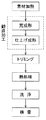
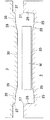
図1はこの発明の実施形態である鍛造加工方法が適用された鍛造製品の製造工程を示すブロック図である。 FIG. 1 is a block diagram showing a manufacturing process of a forged product to which a forging method according to an embodiment of the present invention is applied.
同図に示すように、本実施形態の製造方法は、鍛造素材を加熱した後、鍛造加工を行う。この鍛造加工においては、荒成形(1次成形)と、最終仕上げ成形(2次成形)との2回の鍛造加工を行うものである。 As shown in the figure, the manufacturing method of the present embodiment performs forging after heating the forging material. In this forging process, forging processes of rough forming (primary forming) and final finish forming (secondary forming) are performed twice.
鍛造加工により得られた鍛造加工品は、トリミングにより、バリを除去した後、溶体化処理、焼き入れ処理、および時効処理等の熱処理を行う。その後、鍛造加工品に対し、酸洗浄を行った後、傷や外観等の検査を行って、鍛造製品として出荷するものである。 A forged product obtained by forging is subjected to heat treatment such as solution treatment, quenching treatment, and aging treatment after removing burrs by trimming. After that, the forged product is subjected to acid cleaning, then inspected for scratches and appearance, and shipped as a forged product.
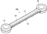
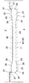
本実施形態の製造方法により製造される鍛造加工品(W2)は図2に示すように、自動車用足廻り部品としてのコントロールアームを構成するものである。この鍛造加工品(W2)は、断面形状が小さい細長の中間軸部(11)と、中間軸部(11)の両端に一体に形成され、かつ断面形状が大きい両端リング部(16)(16)とを備えた複雑な形状を有するものである。なお図2に示す鍛造加工品(W2)は、トリミングによりバリや予肉部を除去した形状のものである。 As shown in FIG. 2, the forged product (W2) manufactured by the manufacturing method of this embodiment constitutes a control arm as an undercarriage part for an automobile. This forged product (W2) has an elongated intermediate shaft portion (11) having a small cross-sectional shape, and both end ring portions (16) (16) formed integrally at both ends of the intermediate shaft portion (11) and having a large cross-sectional shape. And a complicated shape. Note that the forged product (W2) shown in FIG. 2 has a shape in which burrs and pre-wall portions are removed by trimming.
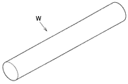
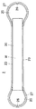
本実施形態において鍛造素材(W)は図4に示すように、外径寸法が長さ方向全域にわたって一定に形成された円柱状のものによって構成されている。本実施形態においてこの鍛造素材(W)は、アルミニウムまたはアルミニウム合金の連続鋳造棒を、トリミング前の鍛造加工品における重量相当分の体積に対応させて、切断して製作するものである。 In this embodiment, as shown in FIG. 4, the forging material (W) is formed of a cylindrical shape having an outer diameter dimension that is uniformly formed over the entire length direction. In the present embodiment, the forging material (W) is manufactured by cutting a continuous cast bar of aluminum or aluminum alloy so as to correspond to the volume corresponding to the weight of the forged product before trimming.
上記鍛造加工品(W2)において、中間軸部(11)の断面積(外径)は、鍛造素材(W)の断面積(外径)よりも小さく形成されるとともに、両端リング部(16)(16)の断面積(外径)は、鍛造素材(W)の断面積(外径)よりも大きく形成されている。 In the forged product (W2), the cross-sectional area (outer diameter) of the intermediate shaft part (11) is formed smaller than the cross-sectional area (outer diameter) of the forged material (W), and both end ring parts (16). The cross-sectional area (outer diameter) of (16) is formed larger than the cross-sectional area (outer diameter) of the forged material (W).
なお本実施形態において、鍛造素材(W)や成形品(W1)(W2)の断面積と言う場合、それらの部材(W)(W1)(W2)における長さ方向(軸心方向)に直交する断面の面積に相当するものである。 In addition, in this embodiment, when saying the cross-sectional area of a forging raw material (W) or a molded product (W1) (W2), it is orthogonal to the length direction (axial center direction) in those members (W) (W1) (W2). This corresponds to the area of the cross section.
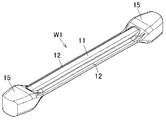
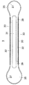
本実施形態においてはこの鍛造素材(W)に荒成形(1次成形)を行って荒成形品(1次成形品W1)を製作するものであるが、この1次成形品(W1)は図3に示すように、両側縁部に沿ってバリ状予肉成形片(12)(12)が形成された中間軸部(11)と、バリ付き中間軸部(11)の両端に一体に形成され、かつ断面積が大きいブロック形状の両端大径部(15)(15)とを備えている。 In the present embodiment, rough forming (primary forming) is performed on the forging material (W) to produce a rough formed product (primary formed product W1). The primary formed product (W1) is illustrated in FIG. As shown in FIG. 3, the intermediate shaft portion (11) in which the burr-like pre-moulded molded pieces (12) and (12) are formed along both side edges and the burr-attached intermediate shaft portion (11) are integrally formed at both ends. And a block-shaped large-diameter end portion (15) (15) having a large cross-sectional area.
なお本実施形態においては、中間軸部(11)およびバリ状予肉成形片(12)とによって、減肉部(小径部)が構成されるとともに、両端大径部(15)によって増肉部が構成されている。 In the present embodiment, the thinned portion (small diameter portion) is constituted by the intermediate shaft portion (11) and the burr-like pre-shaped molded piece (12), and the thickened portion is constituted by the large diameter portions (15) at both ends. Is configured.
この1次成形品(W1)において、バリ状予肉成形片(12)および中間軸部(11)の断面積、つまり減肉部の断面積は、鍛造素材(W)の断面積よりも小さく形成されるとともに、両端大径部(15)(15)の断面積、つまり増肉部の断面積は、鍛造素材(W)の断面積よりも大きく形成されている。 In the primary molded product (W1), the cross-sectional area of the burr-like pre-shaped piece (12) and the intermediate shaft portion (11), that is, the cross-sectional area of the reduced thickness portion is smaller than the cross-sectional area of the forged material (W). While being formed, the cross-sectional areas of the large-diameter portions (15) and (15) at both ends, that is, the cross-sectional area of the thickened portion are formed larger than the cross-sectional area of the forging material (W).
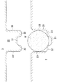
次に鍛造素材(W)に対して荒成形を行うための荒成形用の金型について説明する。図5〜11に示すように、荒成形用の金型(1次成形用金型)は、固定側金型としての下金型(2)と、可動側金型(パンチ)としての上金型(3)とを備えている。 Next, a rough forming die for performing rough forming on the forging material (W) will be described. As shown in FIGS. 5 to 11, a rough molding die (primary molding die) includes a lower die (2) as a fixed side die and an upper die as a movable side die (punch). A mold (3).
下金型(2)の上面側には、1次成形品(W1)の長さ方向中間部(減肉部)を成形するための小径部成形凹部(20)と、長さ方向両端の大径部(15)(15)を成形するための大径部成形凹部(25)(25)とが設けられている。さらに小径部成形凹部(20)における底面の幅方向中間部には、1次成形品(W1)の中間軸部(11)における下側部を成形するための中間軸部成形凹部(21)が設けられている。 On the upper surface side of the lower mold (2), a small-diameter portion molding recess (20) for molding the intermediate portion (thinning portion) in the length direction of the primary molded product (W1), and large portions at both ends in the length direction. Large-diameter portion forming recesses (25) and (25) for forming the diameter portions (15) and (15) are provided. Further, an intermediate shaft portion forming recess (21) for forming the lower side portion of the intermediate shaft portion (11) of the primary molded product (W1) is formed in the intermediate portion in the width direction of the bottom surface of the small diameter portion forming recess (20). Is provided.
上金型(3)の下面側には、下金型(2)の小径部成形凹部(20)に適合状態に挿入可能な小径部成形凸部(30)と、大径部成形凹部(25)(25)に対応する大径部成形凸部(35)(35)とが設けられている。さらに小径部成形凸部(30)における下面の幅方向中間部には、1次成形品(W1)の中間軸部(11)における上側部を成形するための中間軸部成形凹部(31)が設けられている。この中間軸部成形凹部(31)は、下金型(2)の中間軸部成形凹部(21)に対応して設けられている。 On the lower surface side of the upper mold (3), there are a small-diameter molding convex part (30) that can be inserted into a small-diameter molding concave part (20) of the lower mold (2) and a large-diameter molding concave part (25 ) (25) corresponding to the large-diameter portion molding convex portions (35) (35). Further, an intermediate shaft forming concave portion (31) for forming the upper portion of the intermediate shaft portion (11) of the primary molded product (W1) is formed in the intermediate portion in the width direction of the lower surface of the small diameter portion forming convex portion (30). Is provided. The intermediate shaft forming recess (31) is provided corresponding to the intermediate shaft forming recess (21) of the lower mold (2).
そして上金型(3)が降下して下金型(2)に打ち込まれた際には、下金型(2)の小径部成形凹部(20)と上金型(3)の小径部成形凸部(20)とによって、1次成形品(W1)の中間軸部(11)およびバリ状予肉成形片(12)を成形するための空間部(密閉型部40)が形成されるとともに、下金型(2)の大径部成形凹部(25)と上金型(3)の大径部成形凸部(35)とによって、大径部(15)を成形するための空間部(開放型部45)が形成されるようになっている。 When the upper die (3) is lowered and driven into the lower die (2), the small-diameter portion forming recess (20) of the lower die (2) and the small-diameter portion forming of the upper die (3) are formed. The convex part (20) forms a space part (sealed mold part 40) for forming the intermediate shaft part (11) of the primary molded product (W1) and the burr-like pre-moulded molded piece (12). The space portion (15) for molding the large diameter portion (15) by the large diameter portion molding concave portion (25) of the lower mold (2) and the large diameter portion molding convex portion (35) of the upper mold (3). An open mold part 45) is formed.
さらに本実施形態においては図7,8に示すように、下金型(2)の小径部成形凹部(20)における両側内面(23)(23)と、上金型(3)の小径部成形凸部(30)における両側外面(33)(33)とは互いに平行で垂直面に形成されており、荒成形時に、上金型(3)が下金型(2)に打ち込まれた際には、成形途中の段階で、上金型(3)の小径部成形凸部(30)が、下金型(2)の小径部成形凹部(20)に挿入される。この挿入時において、上金型(3)の両側外面(33)(33)と、下金型(3)の両側内面(23)(23)との間には、塑性流動する素材材料が漏れ出さない程度の小さいクリアランスしか形成されていない。従って荒成形中において、上金型(3)の小径部成形凸部(30)の下端面と、下金型(2)の小径部成形凹部(20)の内周面とによって、長さ方向(軸心方向)を除いて周囲方向が密閉された密閉空間が形成されるようになっている。このため本実施形態において荒成形時には、鍛造素材(W)の長さ方向中間部(減肉部)に対し部分的に、はみ出しバリが形成されない密閉鍛造ないし半密閉鍛造が行われるものである。 Furthermore, in this embodiment, as shown in FIGS. 7 and 8, both side inner surfaces (23) and (23) in the small-diameter portion molding recess (20) of the lower die (2) and the small-diameter portion molding of the upper die (3). The protrusions (30) are formed in parallel with each other on the outer surfaces (33) and (33) on the vertical surfaces, and when the upper mold (3) is driven into the lower mold (2) during rough molding. In the middle of molding, the small-diameter portion molding convex portion (30) of the upper die (3) is inserted into the small-diameter portion molding concave portion (20) of the lower die (2). At the time of this insertion, the plastic material material leaks between the outer side surfaces (33) and (33) of the upper mold (3) and the inner surfaces (23) and (23) of the lower mold (3). Only a clearance that is small enough not to come out is formed. Therefore, during rough molding, the lower end surface of the small-diameter portion molding convex portion (30) of the upper die (3) and the inner peripheral surface of the small-diameter portion molding concave portion (20) of the lower die (2) are used in the length direction. A sealed space is formed in which the circumferential direction is sealed except for (axial direction). For this reason, at the time of rough forming in this embodiment, sealed forging or semi-sealed forging in which no protruding burr is formed is partially performed on the intermediate portion (thinned portion) in the length direction of the forging material (W).
ここで本実施形態においては、上金型(3)の小径部成形凸部(30)の下端面と、下金型(2)の小径部成形凹部(20)の内周面とによって密閉された密閉空間が、密閉型部(40)として構成されている。 Here, in this embodiment, it is sealed by the lower end surface of the small-diameter portion molding convex portion (30) of the upper mold (3) and the inner peripheral surface of the small-diameter portion molding concave portion (20) of the lower die (2). The sealed space is configured as a sealed mold part (40).
また上金型(3)の下金型(2)への押し込みが完了した時点(荒成形完了時点)の状態では、上金型(3)における小径部成形凸部(30)の下端面両側(32)(32)と、下金型(2)における小径部成形凹部(20)の底面両側(22)(22)との間には、素材材料が充填される予肉成形用型部(42)(42)が形成される。従って荒成形時においては、鍛造素材(W)の長さ方向中間部における両側の材料の一部が、上記予肉成形用型部(42)(42)に充填されることによって、1次成形品(W1)における中間軸部(11)の両側部には、上記したようにバリ状の予肉成形片(12)(12)が一体に形成されるものである。 In addition, when the upper mold (3) is pushed into the lower mold (2) (when the rough molding is completed), both sides of the lower end surface of the small-diameter molding convex part (30) in the upper mold (3). (32) (32) between the bottom surface side (22) and (22) of the small-diameter portion molding recess (20) in the lower mold (2) (the pre-molding mold portion filled with the raw material ( 42) (42) is formed. Accordingly, at the time of rough forming, a part of the material on both sides in the intermediate portion in the longitudinal direction of the forging material (W) is filled in the pre-molding mold portions (42) (42), thereby performing primary forming. On both sides of the intermediate shaft portion (11) of the product (W1), the burr-like pre-moulded pieces (12) (12) are integrally formed as described above.
なお本実施形態においては、上記密閉型部(40)に、予肉成形用型部(42)(42)が含まれる。 In the present embodiment, the hermetic mold part (40) includes pre-molding mold parts (42) (42).
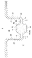
一方図5,6および図9〜11に示すように、下金型(2)における大径部成形凹部(25)(25)の上端開口周縁部(27)(27)と、上金型(3)における大径部成形凸部(35)(35)の外周縁部(37)(37)とは、荒成形時において、上金型(3)の下金型(2)への打ち込みが完了した時点で最も接近ないし接触するように設定されている。このため、鍛造素材(W)の荒成形中には、下金型上端の開口周縁部(27)(27)と、上金型両端の外周縁部(37)(37)との間に隙間が形成されて、両金型(2)(3)によって構成される増肉部成形用空間部(型部)の上縁部が開放された状態となっている。従って荒成形時においては、鍛造素材(W)の長さ方向両端部における大径部(15)(15)に対応する部分に対し、開放鍛造が行われるものである。 On the other hand, as shown in FIGS. 5 and 6 and FIGS. 9 to 11, the upper end opening peripheral portions (27) and (27) of the large-diameter portion molding recesses (25) and (25) in the lower die (2) and the upper die ( The outer peripheral edge portions (37) and (37) of the large-diameter portion forming convex portions (35) and (35) in 3) are driven into the lower die (2) of the upper die (3) during rough forming. It is set to be the closest or touching when completed. For this reason, during rough forming of the forging material (W), there is a gap between the opening peripheral edge (27) (27) at the upper end of the lower mold and the outer peripheral edge (37) (37) at both ends of the upper mold. Is formed, and the upper edge portion of the thickened portion forming space portion (die portion) constituted by both molds (2) and (3) is open. Therefore, at the time of rough forming, open forging is performed on the portions corresponding to the large diameter portions (15) and (15) at both ends in the length direction of the forging material (W).
ここで本実施形態においては、両金型(2)(3)の大径部成形部(25)(35)によって囲まれる大径部成形用空間部が、増肉部形成用型部または開放型部(45)として構成されている。 Here, in the present embodiment, the large-diameter portion forming space surrounded by the large-diameter portion forming portions (25) and (35) of both molds (2) and (3) is the thickened portion forming die portion or the open portion. It is configured as a mold part (45).
また荒成形時には、上記したように両金型(2)(3)における中間部の密閉型部(40)は密閉される一方、密閉型部(40)の両端は、開放型部(45)(45)に連通しているため、荒成形時には、密閉型部(40)おける鍛造素材(W)の余剰材料は、両端の開放型部(45)(45)に塑性流動して、1次成形品(W1)の両端部が増肉されるようになっている。 Further, at the time of rough molding, as described above, the middle mold part (40) in the middle part of both molds (2) and (3) is sealed, while both ends of the mold part (40) are open mold part (45). (45) communicated with each other, at the time of rough forming, surplus material of the forging material (W) in the closed mold part (40) is plastically flowed to the open mold parts (45) and (45) at both ends, and the primary material Both ends of the molded product (W1) are thickened.
また本実施形態において図7〜10に示すように、開放型部(45)(45)における両端側(図7〜10の左右両端側)は、下金型(2)における大径部成形凹部(25)(25)の内周面によって構成される閉塞面(26)(26)が配置されている。このため、荒成形時に、上記したように両金型(2)(3)の密閉型部(40)から両端の開放型部(45)(45)に塑性流動した素材材料は、両端閉塞面(26)(26)によって流動が制御されることにより、両端の開放型部(45)(45)の周囲方向(図7〜10の上下方向)にスムーズに均等に拡散していき、1次成形品(W1)の両端大径部(15)(15)がバランス良く増肉されるようになっている。 Moreover, as shown to FIGS. 7-10 in this embodiment, the both ends side (left-right both ends side of FIGS. 7-10) in an open mold part (45) (45) is a large diameter part shaping | molding recessed part in a lower mold | die (2). (25) The obstruction | occlusion surface (26) (26) comprised by the internal peripheral surface of (25) is arrange | positioned. Therefore, at the time of rough molding, as described above, the material material plastically flowed from the closed mold part (40) of both molds (2) and (3) to the open mold parts (45) and (45) at both ends is closed at both ends. (26) By controlling the flow by (26), the flow is smoothly and evenly diffused in the peripheral direction (vertical direction in FIGS. 7 to 10) of the open mold portions (45) and (45) at both ends. The large diameter portions (15) and (15) at both ends of the molded product (W1) are increased in thickness in a well-balanced manner.
なお本実施形態においては、1次成形品(W1)における中間軸部(11)およびバリ状予肉成形片(12)は、鍛造素材(W)よりも断面積を小さく形成するとともに、両端大径部(15)(15)は、鍛造素材(W)よりも断面積を大きく形成しているため、荒成形時において、鍛造素材(W)の中間部から両端部への材料の塑性流動をスムーズに行うことができる。 In the present embodiment, the intermediate shaft portion (11) and the burr-like pre-shaped molded piece (12) in the primary molded product (W1) are formed to have a smaller cross-sectional area than the forged material (W), and both ends are large. Since the diameter portions (15) and (15) have a larger cross-sectional area than the forged material (W), the plastic flow of the material from the intermediate portion to both ends of the forged material (W) is caused during rough forming. It can be done smoothly.
また本実施形態においては、両金型(2)(3)の密閉型部(40)の断面積は、両端の開放型部(45)の断面積に対し小さく形成しているため、密閉型部(40)と両端の開放型部(45)との間で急激に断面積を変化させてしまうと、その間に段差が形成されることになる。このように段差が形成されると、素材材料を密閉型部(40)から開放型部(45)へスムーズに塑性流動させることができなくなってしまう。
Moreover, in this embodiment, since the cross-sectional area of the sealing mold part (40) of both molds (2) and (3) is formed smaller than the cross-sectional area of the open mold part (45) at both ends, the sealing mold When parts (40) and thereby rapidly changing the cross-sectional area between the open portions at both ends (45), so that the level difference is formed between them. When the step is formed in this way, the raw material cannot be smoothly plastically flowed from the closed mold part (40) to the open mold part (45).
そこで本実施形態においては図5,6に示すように、密閉型部(40)から開放型部(45)にかけて断面積が次第に緩やかに変化するように、両端の開放型部(25)(35)の内周面における密閉型部(40)寄り部分を、テーパー面(29)(39)に形成している。 Therefore, in this embodiment, as shown in FIGS. 5 and 6, the open mold portions (25) and (35) at both ends so that the cross-sectional area gradually changes from the closed mold portion (40) to the open mold portion (45). ) Of the inner peripheral surface closer to the sealed mold portion (40) is formed on the tapered surfaces (29) and (39).
その上さらに、本実施形態においては、このテーパー面(29)(39)を、曲率半径が大きいR付きの湾曲面に形成することにより、材料の塑性流動をより一層スムーズに行うことができ、後述の最終仕上げ成形(2次成形)において、かぶり等の欠陥が発生するのを有効に防止することができる。 Furthermore, in this embodiment, by forming the tapered surfaces (29) and (39) as curved surfaces with R having a large curvature radius, the plastic flow of the material can be performed more smoothly. It is possible to effectively prevent the occurrence of defects such as fogging in final finish molding (secondary molding) described later.
一方、最終仕上げ成形用の金型は、基本的には従来の最終仕上げ用金型と同様である。すなわち、この最終仕上げ用金型は、下金型と上金型とを備え、両金型が閉じられた際に、両金型間に、バリ状余剰成形片(12)を有する鍛造加工品(W2)に対応する形状の成形空間部(型部)が形成されるものである。 On the other hand, the final finishing mold is basically the same as the conventional final finishing mold. That is, this final finishing mold includes a lower mold and an upper mold, and when both molds are closed, a forged product having a burr-like surplus molding piece (12) between both molds. A molding space (mold) having a shape corresponding to (W2) is formed.
なお本実施形態においては、荒成形用金型および仕上げ成形用金型によって鍛造加工装置が構成されている。 In the present embodiment, the forging device is constituted by the rough forming die and the finish forming die.
本実施形態においては、以上の構成の荒成形用の金型および仕上げ成形用の金型を用いて、鍛造素材(W)に対し、荒成形(1次成形)および仕上げ成形(2次成形)を行って、鍛造加工品(W2)を製作するものである。 In the present embodiment, rough forming (primary forming) and finish forming (secondary forming) are performed on the forging material (W) using the rough forming die and the finish forming die having the above-described configuration. To produce a forged product (W2).
すなわち図5,7,10に示すように、予備加熱を行った鍛造素材(W)を、荒成形用金型の下金型(2)における小径部成形凹部(20)内にセットする。なお、鍛造素材(W)の予備加熱(素材加熱温度)は、480〜550℃に設定するのが好ましい。 That is, as shown in FIGS. 5, 7, and 10, the pre-heated forged material (W) is set in the small-diameter portion forming recess (20) in the lower die (2) of the rough forming die. In addition, it is preferable to set the preheating (raw material heating temperature) of a forge raw material (W) to 480-550 degreeC.
また鍛造素材(W)の長さは、小径部成形凹部(20)の長さよりも少し長い程度であり、下金型(2)にセットした状態においては、鍛造素材(W)の両端部が、大径部成形凹部(25)(25)の位置に、部分的に配置されるのみである。 Further, the length of the forging material (W) is slightly longer than the length of the small-diameter portion forming recess (20), and in the state set in the lower die (2), both end portions of the forging material (W) are They are only partially disposed at the positions of the large-diameter portion molding recesses (25) and (25).
この状態で図6,9に示すように、上金型(3)を降下させて下金型(2)に打ち込む。このとき、鍛造素材(W)は、両金型(2)(3)によって上下両側から挟圧されて、塑性変形していき、その成形途中において、上金型(3)の小径部成形凸部(30)および下金型(2)の小径部成形凹部(20)によって、上記したように密閉状態の密閉型部(40)が形成されるとともに、両端の大径部成形凸部(35)および大径部成形凹部(25)によって、開放状態の開放型部(45)(45)が形成される。そして密閉型部(40)における中間軸部成形凹部(21)(31)および予肉成形用型部(42)(42)に素材材料が充填されて、1次成形品(W1)の中間軸部(11)およびバリ状予肉成形片(12)(12)が成形される。 In this state, as shown in FIGS. 6 and 9, the upper mold (3) is lowered and driven into the lower mold (2). At this time, the forging material (W) is clamped from both the upper and lower sides by both molds (2) and (3) and is plastically deformed. As described above, the sealed mold part (40) in the sealed state is formed by the small diameter part molding concave part (20) of the part (30) and the lower mold (2), and the large diameter part molding convex part (35 at both ends). ) And the large-diameter portion molding recess (25) form an open mold portion (45) (45) in an open state. The intermediate shaft portion of the primary molded product (W1) is filled with the raw material in the intermediate shaft portion molding recesses (21) (31) and the pre-moulding mold portions (42) (42) in the sealed mold portion (40). A part (11) and a burr-like pre-mesh molded piece (12) (12) are molded.
一方図6に示すように、密閉型部(40)は、鍛造素材(W)よりも断面積が小さいため、余剰の素材材料が発生し、その余剰の素材材料が上記した開放型部(45)(45)内に充填されていく。さらに開放型部(45)(45)に流入される素材材料は、上記の両端閉塞面(26)(26)によって流動が制御され、それにより素材材料が、両端開放型部(45)(45)を周囲方向にバランス良く拡散して、開放型部(45)(45)内のほぼ全域に均等に充填されて、1次成形品(W1)の両端大径部(15)(15)が確実に成形される。 On the other hand, as shown in FIG. 6, since the closed mold part (40) has a smaller cross-sectional area than the forged material (W), surplus material material is generated, and the surplus material material is the open mold part (45 ) (45). Furthermore, the flow of the material material flowing into the open mold parts (45) and (45) is controlled by the both-end closed surfaces (26) and (26). ) In a well-balanced manner in the peripheral direction, and the entire area of the open mold part (45) (45) is uniformly filled, and the large diameter parts (15) (15) at both ends of the primary molded product (W1) are formed. Molded reliably.
なお荒成形時において、下金型(2)における両端の開口周縁部(27)と、上金型(3)における両端の外周縁部(37)との間には隙間が形成されるため、両端開放型部(45)(45)内で余剰となった素材材料は、上記の隙間から外部に排出されて、はみ出しバリが形成されることになる。ここで、本実施形態においては、両端開放型部(45)(45)は、はみ出しバリが形成可能な鍛造加工を行うことができる型部として構成されている。 At the time of rough molding, a gap is formed between the opening peripheral edge (27) at both ends of the lower mold (2) and the outer peripheral edge (37) at both ends of the upper mold (3). The surplus material in the open ends (45) and (45) is discharged to the outside through the gap, and a protruding burr is formed. Here, in this embodiment, both-end open mold part (45) (45) is comprised as a mold part which can perform the forging process which can form a protrusion burr | flash.
こうして荒成形された1次成形品(W1)は図3に示すように、両側縁部に沿ってバリ状予肉成形片(12)(12)が形成された中間軸部(11)の両端に、ブロック形状の大径部(15)(15)が一体に形成された形状に成形される。 As shown in FIG. 3, the primary molded product (W1) thus roughly formed has both ends of the intermediate shaft portion (11) on which the burr-like pre-moulded pieces (12) (12) are formed along both side edges. In addition, the block-shaped large-diameter portions (15) and (15) are formed into a shape integrally formed.
なお図示は省略されているが、下金型(2)の内部には、成形された1次成形品(W1)を排出するためのノックアウトピンが設置されており、このノックアウトピンによって、荒成形後の1次成形品(W1)が下金型(2)の内部から排出されるようになっている。 Although not shown, a knockout pin for discharging the molded primary molded product (W1) is installed inside the lower mold (2). By this knockout pin, rough molding is performed. The subsequent primary molded product (W1) is discharged from the inside of the lower mold (2).
次にこの1次成形品(W1)を、上記したように最終仕上げ成形用の金型にセットして、最終仕上げ成形(2次成形)を行う。こうして仕上げ成形された2次成形品としての鍛造加工品(W2)は図2の想像線に示すように、1次成形品(W1)に対し、中間軸部(11)およびバリ状予肉成形片(12)は、ほぼそのままの形状で、両端の大径部(15)(15)がリング部(16)に成形される。 Next, this primary molded product (W1) is set in a final finish molding die as described above, and final finish molding (secondary molding) is performed. The forged product (W2) as the secondary molded product thus finished is compared with the primary molded product (W1) as shown by the imaginary line in FIG. The piece (12) has almost the same shape, and the large diameter portions (15) and (15) at both ends are formed into the ring portion (16).
なお仕上げ成形用金型の下金型においても、上記荒成形用の下金型と同様に、ノックアウトピンが設置されており、このノックアウトピンによって、仕上げ成形後の2次成形品(W2)が仕上げ成形用金型から排出されるようになっている。 In the lower mold of the finish molding die, a knockout pin is installed in the same manner as the lower mold for rough molding. By this knockout pin, the secondary molded product (W2) after the finish molding is formed. It is discharged from the finishing mold.
また仕上げ成形された2次成形品(鍛造加工品W2)は、トリミング工程において、バリ状予肉成形片(12)(12)や、両端リング部(16)(16)の外周縁に設けられたはみ出しバリ(図示省略)が切除される。 In addition, the finish-formed secondary molded product (forged product W2) is provided on the outer peripheral edge of the burr-like pre-moulded molded pieces (12) (12) and the ring portions (16) (16) at both ends in the trimming step. A protruding burr (not shown) is cut off.
さらにトリミングされた鍛造加工品(W2)は、上記図1に示すように、熱処理工程、酸洗浄工程、検査工程を経た後、鍛造製品として出荷される。 The trimmed forged product (W2) is shipped as a forged product after undergoing a heat treatment step, an acid cleaning step, and an inspection step, as shown in FIG.
以上のように、本実施形態における鍛造製品の製造方法によれば、鍛造加工の荒成形時に、中間軸部(11)およびバリ状予肉成形片(12)に対応する部分に対し、密閉鍛造を行うとともに、それ以外の部分(大径部15)に対応する部分に対し、開放鍛造を行うようにしているため、荒成形時に、鍛造素材(W)の中間部における余剰の材料は、両端側にスムーズに流動して、両端部を確実に増肉させることができる。このため、荒成形によって得られた1次成形品(W1)は、そのボリュームバランスを、最終仕上げ成形後の鍛造加工品(W2)に近づけることができ、1次成形品(W1)をそのまま最終仕上げ成形することによって、高い寸法精度を有する鍛造加工品(W2)を確実に作製することができる。このように本実施形態の鍛造加工においては、荒成形と仕上げ成形とのたった2回の鍛造加工によって、鍛造素材(W)を最終仕上げ形状の鍛造加工品(W2)に確実に形成することができるため、鍛造回数が少なく、鍛造工程数の削減により、生産効率の向上およびコストの削減を図ることができる。 As described above, according to the method for producing a forged product in the present embodiment, closed forging is performed on portions corresponding to the intermediate shaft portion (11) and the burr-like pre-shaped formed piece (12) at the time of rough forming in the forging process. Since the forging is performed on the portion corresponding to the other portion (large diameter portion 15), the surplus material in the intermediate portion of the forging material (W) is at both ends during rough forming. It can flow smoothly to the side, and both ends can be reliably increased in thickness. For this reason, the primary molded product (W1) obtained by the rough molding can bring the volume balance close to that of the forged product (W2) after final finish molding, and the primary molded product (W1) can be finished as it is. By performing finish molding, a forged product (W2) having high dimensional accuracy can be reliably produced. As described above, in the forging process of the present embodiment, the forging material (W) can be reliably formed into the forged product (W2) having the final finish shape by only two forging processes including the rough forming and the finish forming. Therefore, the number of forgings is small, and the reduction in the number of forging steps can improve production efficiency and reduce costs.
さらに本実施形態においては、荒成形用の金型と、仕上げ成形用の金型とのたった2種類の金型を準備するだけで、鍛造加工品(W2)を製造することができる。つまり、荒成形用金型および仕上げ成形用金型以外の金型、例えば後述するように中間成形用の金型を作製する必要がなく、その分、金型の製作費を削減でき、より一層コストを削減することができる。 Furthermore, in this embodiment, a forged product (W2) can be manufactured by preparing only two types of molds, ie, a rough mold and a finish mold. In other words, it is not necessary to prepare a mold other than the rough mold and the finish mold, for example, an intermediate mold as will be described later, and the production cost of the mold can be reduced accordingly. Cost can be reduced.
また本実施形態においては、鍛造素材(W)に対しそのままの状態で鍛造加工するものであるため、鍛造素材に対し、予備成形を行ってボリュームバランスを調整する必要がない。このように予備成形を行う必要がない分、作業工程数を削減することができ、この点においても、一層、生産効率の向上およびコストの削減を図ることができる。 In the present embodiment, the forging material (W) is forged as it is, and therefore it is not necessary to perform preforming on the forging material and adjust the volume balance. Since there is no need for preforming in this way, the number of work steps can be reduced, and in this respect as well, production efficiency can be further improved and costs can be reduced.
同様に、本実施形態においては、鍛造加工時に、鍛造素材(W)や1次成形品(W1)を再加熱して、加工性を向上させる必要がなく、再加熱を行わない分、作業工程数を削減でき、より一層、生産効率の向上およびコストの削減を図ることができる。 Similarly, in this embodiment, it is not necessary to reheat the forging material (W) or the primary molded product (W1) during forging, so that workability does not need to be improved, and the reworking is not performed. The number can be reduced, and the production efficiency can be further improved and the cost can be reduced.
また本実施形態においては、荒成形時に鍛造素材(W)の中間部に対し密閉鍛造を行って、余剰の素材材料を両端部に塑性流動させることにより、増肉させるようにしているため、バリの発生量が少なくなり、材料の有効利用を図ることができ、材料歩留まりを向上させることができるとともに、なお一層、コストを削減することができる。 In this embodiment, since the forging material (W) is subjected to hermetic forging at the time of rough forming and the excess material material is plastically flowed at both ends, the thickness of the forging material (W) is increased. As a result, the material yield can be improved and the cost can be further reduced.
また本実施形態においては、1次成形(荒成形)によって最終仕上げ形状の鍛造加工品(W2)に近い形状に成形することができるため、鍛造加工後の熱処理工程(溶体化処理)において、再結晶化を抑制することができる。従って、鍛造製品の強度低下を防止でき、品質をより一層向上させることができる。 Moreover, in this embodiment, since it can shape | mold in the shape close | similar to the forged product (W2) of a final finish shape by primary shaping | molding (rough shaping), in the heat treatment process (solution treatment) after forging, Crystallization can be suppressed. Therefore, the strength reduction of the forged product can be prevented, and the quality can be further improved.
なお参考までに、荒成形において、鍛造素材(W)の中間部に対し、密閉鍛造を行わずに、開放鍛造を行った場合には、その荒成形によって得られた荒成形品は、後に詳述するように、ボリュームバランスを最終仕上げ形状の鍛造加工品に近づけることができず、荒成形後に、別途、中間成形を行って、中間品を作製した後、その中間品に対し、最終仕上げ成形を行う必要がある。
For reference, in rough forming, when open forging is performed on the intermediate part of the forging material (W) without performing closed forging, the rough formed product obtained by the rough forming will be described in detail later. As described above, the volume balance cannot be brought close to the final finished forged product, and after rough forming, intermediate forming is performed separately to produce the intermediate product, and then final finishing molding is performed on the intermediate product. Need to do.
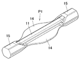
すなわち鍛造素材(W)に対し中間部を密閉せずに鍛造を行って荒成形された荒成形品(P1)は図13に示すように、その中間軸部(11)の両側縁部に両側方に大きく張り出した大容量のはみ出しバリ(14)(14)が形成される。このはみ出しバリ(14)(14)は、除去されて廃棄されるものであるため、材料の無駄となり、材料歩留まりが悪化してしまう。 That is, as shown in FIG. 13, the rough molded product (P1) which is rough-formed by forging without sealing the intermediate portion with respect to the forging material (W) has both sides on both side edges of the intermediate shaft portion (11). A large-capacity protruding burr (14) (14) is formed which protrudes greatly in the direction. Since the protruding burrs (14) and (14) are removed and discarded, the material is wasted and the material yield is deteriorated.
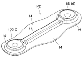
さらに荒成形時に、中間部の余剰材料は、そのほとんどがバリ(14)となるため、中間部の余剰材料を、例えば両端の大径部(15)(15)等に、十分に塑性流動させることができず、既述したように、ボリュームバランスを最終仕上げ形状の鍛造加工品(W2)に近づけることが困難である。このため、荒成形を行った荒成形品(P1)に対し、別途、中間成形を行って図14に示すように、鍛造加工品(W2)のボリュームバランスに近い中間成形品(P2)を作製し、その中間成形品(P2)に対し、上記実施形態と同様に、最終仕上げ成形を行って、鍛造加工品(W2)を作製する必要がある。 Further, since most of the surplus material in the intermediate portion becomes burrs (14) during rough forming, the surplus material in the intermediate portion is sufficiently plastically flowed to, for example, the large diameter portions (15) and (15) at both ends. As described above, it is difficult to bring the volume balance closer to the final finished forged product (W2). For this reason, the intermediate molded product (P2) that is close to the volume balance of the forged product (W2) as shown in FIG. Then, it is necessary to perform final finish molding on the intermediate molded product (P2) in the same manner as in the above embodiment to produce a forged product (W2).
このように部分的な密閉鍛造を用いずに、自動車用足廻り部品のような複雑な形状の鍛造加工品(W2)を製造する場合には、中間成形(中間鍛造)を余計に行う必要があり、その分、生産性の低下を来すとともに、コストも増大してしまう。さらに、鍛造加工後に大きなバリ(14)が形成されるため、つまり廃棄処分される材料が多く発生するため、材料歩留まりが悪化し、この点においても、一段とコストの増大を招いてしまう。 Thus, when producing a forged product (W2) having a complicated shape such as an automobile suspension part without using partial hermetic forging, it is necessary to perform intermediate forming (intermediate forging). There is a corresponding reduction in productivity and an increase in cost. Furthermore, since a large burr ( 14 ) is formed after forging, that is, a large amount of material to be discarded is generated, the material yield is deteriorated, and in this respect, the cost is further increased.
これに対し本実施形態の鍛造加工方法においては、荒成形時に、部分的な密閉鍛造を行うものであるため、既述したように、工程数の削減により、生産性の向上、材料歩留まりの向上およびコストの削減を確実に図ることができる。 In contrast, in the forging method according to the present embodiment, partial hermetic forging is performed at the time of rough forming, and as described above, by reducing the number of steps, productivity is improved and material yield is improved. In addition, the cost can be surely reduced.
図12はこの発明の鍛造加工方法によって製造可能な鍛造加工品(W2)を示す図である。この鍛造加工品(W2)は、自動車用フロントアッパーアームを構成するものである。この鍛造加工品(W2)は、概略U字状(逆U字状)に形成されており、その両側片によって構成されるアーム部(101)(101)は、断面形状が小さい小径部(減肉部)として構成されるとともに、両アーム部(101)(101)間に、断面積の大きい増肉部としての中間大径部(103)が一体に形成され、さらに両アーム部(101)(101)の端部に、断面積の大きい両端大径部(105)(105)が一体に形成されている。 FIG. 12 is a view showing a forged product (W2) that can be manufactured by the forging method of the present invention. This forged product (W2) constitutes an automobile front upper arm. This forged product (W2) is formed in a substantially U shape (inverted U shape), and the arm portions (101) (101) constituted by both side pieces thereof are small diameter portions (reduced diameter) having a small cross-sectional shape. The middle large-diameter portion (103) as a thickened portion having a large cross-sectional area is integrally formed between the arm portions (101) and (101). Both end large diameter portions (105) and (105) having a large cross-sectional area are integrally formed at the end portion of (101).
この鍛造加工品(W2)は、上記実施形態と同様に、鍛造素材(W)に対し、荒成形(1次成形)と、最終仕上げ成形(2次成形)との2回の鍛造加工を行って製造するものである。 This forged product (W2) is subjected to two forging processes of rough forming (primary forming) and final finish forming (secondary forming) with respect to the forging material (W) as in the above embodiment. Are manufactured.
この場合、荒成形時においては、両アーム部(101)(101)に対応する部分(同図の密閉鍛造部に示す範囲)に対し、上記実施形態と同様な密閉型部よる密閉鍛造が行われるとともに、それ以外の部分、中間大径部(103)および両端大径部(105)(105)に対応する部分に対し、上記実施形態と同様な開放型部による開放鍛造が行われるものである。 In this case, at the time of rough forming, the sealing forging by the sealing mold portion similar to the above embodiment is performed on the portions corresponding to the both arm portions (101) and (101) (the range shown in the sealing forging portion in the figure). In addition, the open forging by the open mold part similar to the above embodiment is performed on the other parts, the parts corresponding to the intermediate large diameter part (103) and the large end diameter parts (105) (105). is there.
鍛造素材(W)としては、同図想像線に示すように、断面積(外径)が一定の円柱部材をU字状に曲げ成形したものが用いられている。この鍛造素材(W)は、その断面積(外径)が、アーム部(101)の断面積(外径)よりも大きくて、中間大径部(103)および両端大径部(105)の断面積(外径)よりも小さく形成されている。さらに鍛造素材(W)の両端部は、両端大径部(105)(105)に対応する部分まで至らず、アーム部(101)(101)の端部に配置されている。 As the forging material (W), as shown in the imaginary line, a forged cylindrical member having a constant cross-sectional area (outer diameter) is formed into a U shape. The forged material (W) has a cross-sectional area (outer diameter) larger than the cross-sectional area (outer diameter) of the arm part (101), and the intermediate large-diameter part (103) and both end large-diameter parts (105). It is formed smaller than the cross-sectional area (outer diameter). Furthermore, the both ends of the forged material (W) do not reach the portions corresponding to the large-diameter portions (105) and (105) at both ends, but are disposed at the ends of the arm portions (101) and (101).
この鍛造素材(W)を、そのアーム部(101)に対応する部分を密閉した状態で鍛造加工(荒成形)した際には、鍛造素材(W)のアーム部(101)に対応する部分の余剰材料が、中間大径部(103)および両端大径部(105)(105)に塑性流動され、その部分の増肉が図られる。 When this forging material (W) is forged (roughly formed) with the portion corresponding to the arm portion (101) sealed, the portion corresponding to the arm portion (101) of the forging material (W) The surplus material is plastically flowed into the intermediate large diameter portion (103) and the both end large diameter portions (105) and (105), and the thickness of the portions is increased.
なおこの変形例においても荒成形による1次成形品には、アーム部(101)の両側部に沿って、上記実施形態と同様に、バリ状予肉成形片が形成されるものである。さらにこの変形例においても、上記実施形態と同様で、1次成形品におけるアーム部(101)およびバリ状予肉成形片によって減肉部が構成される。 In this modified example as well, a burr-like pre-formed piece is formed along the both side portions of the arm portion (101) in the primary molded product by rough forming, as in the above embodiment. Further, in this modified example as well, the reduced thickness portion is constituted by the arm portion (101) and the burr-like pre-shaped molded piece in the primary molded product as in the above embodiment.
この変形例の鍛造加工品(W2)を製造する場合においても、上記実施形態と同様に、荒成形において、最終仕上げ形状の鍛造加工品(W2)のボリュームバランスに近い1次成形品を得ることができると同時に、材料の有効利用を図ることができ、上記と同様に、生産性の向上、材料歩留まりの向上およびコストの削減を図ることができる。 Even in the case of manufacturing the forged product (W2) of this modified example, a primary molded product close to the volume balance of the final-finished forged product (W2) is obtained in the rough forming as in the above embodiment. At the same time, the material can be used effectively, and as described above, productivity, material yield, and cost can be improved.
なお上記実施形態等においては、1次成形品(W1)の大径部の断面積(外径)が、鍛造素材(W)の断面積(外径)よりも大きい場合を例に挙げて説明したが、それだけに限られず、本発明においては、大径部の断面積(外径)が、鍛造素材(W)の断面積(外径)に対し、同等または小さい場合にも適用することができる。要は、1次成形品(W1)の小径部(減肉部)、つまり密閉鍛造する部分(部位)の断面積が、鍛造素材(W)の断面積よりも小さい場合には、本発明を適用することができる。 In the above-described embodiment, the case where the cross-sectional area (outer diameter) of the large-diameter portion of the primary molded product (W1) is larger than the cross-sectional area (outer diameter) of the forged material (W) will be described as an example. However, the present invention is not limited to this, and in the present invention, the present invention can also be applied to the case where the cross-sectional area (outer diameter) of the large-diameter portion is equal to or smaller than the cross-sectional area (outer diameter) of the forged material (W). . In short, when the cross-sectional area of the small-diameter portion (thinned portion) of the primary molded product (W1), that is, the portion (part) to be hermetically forged is smaller than the cross-sectional area of the forging material (W), the present invention is Can be applied.
また上記実施形態においては、荒成形において、鍛造素材の大径部に対応する部分を、開放型部による開放鍛造を行うようにしているが、それだけに限られず、本発明においては、大径部成形用の型部の容量が十分に確保されるような場合には、大径部に対し密閉型部(半密閉型部)による密閉鍛造(半密閉鍛造)を行って1次成形(荒成形)するようにしても良い。 Further, in the above embodiment, in rough forming, the portion corresponding to the large diameter portion of the forging material is subjected to open forging by the open die portion, but is not limited thereto, and in the present invention, the large diameter portion forming is performed. When the capacity of the mold part is sufficiently secured, primary forging (rough forming) is performed by sealing forging (semi-sealing forging) with a sealing mold part (semi-sealing mold part) on the large diameter part. You may make it do.
また本発明においては、1次成形用金型(荒成形用金型)や、2次成形用金型(最終仕上げ成形用金型)の材質(金型材質)は特に限定されるものではなく、例えばごく一般に用いられる工具鋼を好適に用いることができる。 In the present invention, the material (mold material) of the primary mold (rough mold) or the secondary mold (final finish mold) is not particularly limited. For example, a tool steel that is generally used can be preferably used.
<実施例>
ピーリング処理を施した円柱形状のアルミニウム合金製の鍛造素材(直径31mm、長さ218mm)を準備し、この鍛造素材を、500℃に加熱(予備加熱)した。そして、加熱後の鍛造素材に対し、上記実施形態に準拠した部分密閉式の鍛造による荒成形(1次成形)と、最終仕上げ成形(2次成形)との2回の鍛造加工を行った後、トリミングによりバリや予肉部を除去して、上記図2に示す実施形態と同様な形状の鍛造加工品を作製した。
<Example>
A forging material (
こうして得られた鍛造加工品を検査したところ、欠肉等の欠陥もなく、高い寸法精度も得ることができ、高品質の鍛造加工品であることを確認できた。さらにこの鍛造加工品を製造するに際して、材料歩留まりを計測したところ、鍛造素材に対し、鍛造加工品の材料歩留まりは73%であった。 When the forged product thus obtained was inspected, it was confirmed that it was a high-quality forged product without defects such as lack of wall and high dimensional accuracy. Further, when the forged product was manufactured, the material yield was measured. As a result, the forged material had a material yield of 73%.
<比較例>
長さが245mmに設定した以外は、上記と同様な鍛造素材を準備した。そして上記と同様の条件で加熱した後、その鍛造素材に対し、従来技術に準拠した全開放式の荒成形と、中間成形と、最終仕上げ成形との3回の鍛造加工を行った後、上記と同様にして、同形状の鍛造加工品を作製した。
<Comparative example>
A forging material similar to the above was prepared except that the length was set to 245 mm. And after heating under the same conditions as described above, the forging material was subjected to forging three times of fully open rough forming, intermediate forming, and final finish forming in accordance with the prior art, In the same manner, a forged product having the same shape was produced.
こうして得られた鍛造加工品を検査したところ、欠肉等の欠陥もなく、高い寸法精度も得ることができた。しかしながら、鍛造素材に対する鍛造加工品の材料歩留まりを計測したところ、58%であった。 When the forged product thus obtained was inspected, it was found that there was no defect such as lack of wall and high dimensional accuracy could be obtained. However, when the material yield of the forged product with respect to the forged material was measured, it was 58%.
<評価>
上記の実施例および比較例から明らかなように、本発明に関連した実施例の鍛造加工方法は、従来の鍛造加工方法に比べて、材料歩留まりが15%も向上しており、コストの削減を確実に図ることができると考えられる。
<Evaluation>
As is clear from the above examples and comparative examples, the forging method of the example related to the present invention has a material yield improved by 15% compared with the conventional forging method, thereby reducing the cost. It is thought that it can be surely achieved.
この発明の鍛造加工方法は、部分的に断面積が異なり、減肉部等を有する鍛造加工品を製造する際に利用することができる。 The forging method of the present invention can be used when manufacturing a forged product having a partially reduced cross-sectional area and having a reduced thickness portion or the like.
11…中間軸部(減肉部)
12…バリ状予肉成形片(減肉部)
15…大径部(増肉部)
14…はみ出しバリ
16…両端リング部
26…閉塞面
29,39…テーパー部
40…密閉型部
42…予肉成形型部
45…開放型部(増肉部成形用型部)
W…鍛造素材
W1…1次成形品
W2…鍛造加工品
11 ... Intermediate shaft (thinned part)
12 ... Burr-like pre-moulded piece (thinned part)
15 ... Large diameter part (thickening part)
14 ... Extruding
W ... Forging material W1 ... Primary molded product W2 ... Forged product
Claims (17)
1次成形品に対し型成形による2次成形を行って鍛造加工品を得る2次成形工程と、を含み、
前記1次成形工程において、鍛造素材の少なくとも前記減肉部に対応する部分に対し、1次成形用金型の密閉型部によって、はみ出しバリが形成されない密閉鍛造を行うようにし、
1次成形品の端部における前記減肉部とは異なる部分に、増肉部が設けられ、
前記1次成形によって、鍛造素材の材料を前記減肉部に対応する部分から前記増肉部に対応する部分に塑性流動させるようにし、
前記増肉部は、鍛造素材に対して、外径が大きく形成され、
前記1次成形工程において、鍛造素材の前記増肉部に対応する部分に対し、はみ出しバリが形成可能な開放鍛造を行うとともに、
前記1次成形工程において、1次成形用金型の端部に設けられた閉塞面によって、前記増肉部に流入される素材材料を外径方向に誘導させるようにし、
前記1次成形用金型は、下金型と、上金型とを備え、
前記下金型の上面側には、小径部成形凹部が設けられるとともに、前記上金型の下面側には、前記小径部成形凹部に適合状態に挿入可能な小径部成形凸部が設けられ、
前記上金型の小径部成形凸部の下端面と、下金型の小径部成形凹部の内周面とによって密閉された密閉空間が、前記密閉型部として構成され、
前記下金型の小径部成形凹部における両側内面と、前記上金型の小径部成形凸部における両側外面とは互いに平行で垂直面に形成されていることを特徴とする鍛造加工方法。 A primary molding step of performing primary molding by die molding on the forging material to obtain a primary molded product having a thinned portion having a small cross-sectional area with respect to the forging material;
A secondary molding step of obtaining a forged product by performing secondary molding by mold molding on the primary molded product,
In the primary forming step, forging at least a portion corresponding to the reduced-thickness portion of the forging material is performed by hermetic forging in which no protruding burr is formed by the hermetic mold portion of the primary molding die,
A thickened portion is provided in a portion different from the thinned portion at the end of the primary molded product,
By the primary molding, the material of the forging material is plastically flowed from the portion corresponding to the reduced thickness portion to the portion corresponding to the increased thickness portion,
The thickened portion is formed with a large outer diameter with respect to the forging material,
In the primary molding process, for the portion corresponding to the increased thickness portion of the forging material, performing open forging capable of forming a protruding burr,
In the primary molding step, the closing material provided at the end of the primary molding die guides the material material flowing into the thickened portion in the outer diameter direction,
The primary molding die includes a lower die and an upper die,
On the upper surface side of the lower mold, a small-diameter portion molding concave portion is provided, and on the lower surface side of the upper mold, a small-diameter portion molding convex portion that can be inserted into the small-diameter portion molding concave portion is provided.
A sealed space sealed by the lower end surface of the small-diameter portion molding convex portion of the upper mold and the inner peripheral surface of the small-diameter portion molding concave portion of the lower mold is configured as the sealed mold portion,
A forging method characterized in that the inner surfaces on both sides of the small-diameter portion forming concave portion of the lower mold and the outer surfaces on both sides of the small-diameter portion forming convex portion of the upper die are formed in parallel and vertical surfaces.
前記増肉部成形用型部は、前記密閉型部よりも型内径が大きく形成され、
前記増肉部成形用型部の内周面における前記密閉型部寄りの領域は、型内径が次第に変化するテーパー部に形成されている請求項1に記載の鍛造加工方法。 The primary molding die is provided with a thickening part molding die part for molding a material material plastically flowed from the sealed mold part,
The thickening part molding mold part is formed with a larger mold inner diameter than the sealed mold part,
2. The forging method according to claim 1, wherein the region near the sealed mold part on the inner peripheral surface of the thickening part forming mold part is formed in a tapered part in which a mold inner diameter gradually changes .
1次成形品に対し型成形による2次成形を行って鍛造加工品を得る2次成形工程と、を含み、
前記1次成形工程において、鍛造素材の少なくとも前記減肉部に対応する部分に対し、1次成形用金型の密閉型部によって、はみ出しバリが形成されない密閉鍛造を行うようにし、
1次成形品の端部における前記減肉部とは異なる部分に、増肉部が設けられ、
前記1次成形によって、鍛造素材の材料を前記減肉部に対応する部分から前記増肉部に対応する部分に塑性流動させるようにし、
前記増肉部は、鍛造素材に対して、外径が大きく形成され、
前記1次成形工程において、1次成形用金型の端部に設けられた閉塞面によって、前記増肉部に流入される素材材料を外径方向に誘導させるようにし、
前記1次成形用金型は、下金型と、上金型とを備え、
前記下金型の上面側には、小径部成形凹部が設けられるとともに、前記上金型の下面側には、前記小径部成形凹部に適合状態に挿入可能な小径部成形凸部が設けられ、
前記上金型の小径部成形凸部の下端面と、下金型の小径部成形凹部の内周面とによって密閉された密閉空間が、前記密閉型部として構成され、
前記下金型の小径部成形凹部における両側内面と、前記上金型の小径部成形凸部における両側外面とは互いに平行で垂直面に形成され、
前記1次成形用金型には、前記密閉型部から塑性流動させた素材材料を成形する増肉部成形用型部が設けられ、
前記増肉部成形用型部は、前記密閉型部よりも型内径が大きく形成され、
前記増肉部成形用型部の内周面における前記密閉型部寄りの領域は、型内径が次第に変化するテーパー部に形成されていることを特徴とする鍛造加工方法。 A primary molding step of performing primary molding by die molding on the forging material to obtain a primary molded product having a thinned portion having a small cross-sectional area with respect to the forging material;
A secondary molding step of obtaining a forged product by performing secondary molding by mold molding on the primary molded product,
In the primary forming step, forging at least a portion corresponding to the reduced-thickness portion of the forging material is performed by hermetic forging in which no protruding burr is formed by the hermetic mold portion of the primary molding die,
A thickened portion is provided in a portion different from the thinned portion at the end of the primary molded product,
By the primary molding, the material of the forging material is plastically flowed from the portion corresponding to the reduced thickness portion to the portion corresponding to the increased thickness portion,
The thickened portion is formed with a large outer diameter with respect to the forging material,
In the primary molding step, the closing material provided at the end of the primary molding die guides the material material flowing into the thickened portion in the outer diameter direction,
The primary molding die includes a lower die and an upper die,
On the upper surface side of the lower mold, a small-diameter portion molding concave portion is provided, and on the lower surface side of the upper mold, a small-diameter portion molding convex portion that can be inserted into the small-diameter portion molding concave portion is provided.
A sealed space sealed by the lower end surface of the small-diameter portion molding convex portion of the upper mold and the inner peripheral surface of the small-diameter portion molding concave portion of the lower mold is configured as the sealed mold portion,
The inner surfaces on both sides in the small-diameter portion molding concave portion of the lower mold and the outer surfaces on both sides in the small-diameter portion molding convex portion of the upper die are formed in parallel and vertical surfaces,
The primary molding die is provided with a thickening part molding die part for molding a material material plastically flowed from the sealed mold part,
The thickening part molding mold part is formed with a larger mold inner diameter than the sealed mold part,
The forging method characterized in that the region near the sealed mold part on the inner peripheral surface of the thickened part molding die part is formed in a tapered part where the inner diameter of the mold gradually changes .
前記2次成形は、最終仕上げ成形を構成するものである請求項1〜6のいずれか1項に記載の鍛造加工方法。 The primary molding constitutes rough molding,
The forging method according to any one of claims 1 to 6 , wherein the secondary forming constitutes final finish forming.
1次成形品に対し2次成形を行って鍛造加工品を得るための2次成形用金型と、を備え、
前記1次成形用金型における鍛造素材の少なくとも前記減肉部を成形する部分が、はみ出しバリが形成されない密閉型部に構成され、
前記1次成形用金型には、前記密閉型部から塑性流動させた素材材料を成形する増肉部成形用型部が設けられ、
前記増肉部成形用型部は、前記密閉型部よりも型内径が大きく形成されるとともに、前記1次成形用金型の端部に配置され、
前記増肉部成形用型部は、はみ出しバリが形成可能な開放型部として構成され、
前記増肉部成形用型部の内周面には、前記密閉型部から塑性流動させた素材材料を、外径方向に誘導するための閉塞面が設けられ、
1次成形用の金型は、下金型と、上金型とを備え、
前記下金型の上面側には、小径部成形凹部が設けられるとともに、前記上金型の下面側には、前記小径部成形凹部に適合状態に挿入可能な小径部成形凸部が設けられ、
前記上金型の小径部成形凸部の下端面と、下金型の小径部成形凹部の内周面とによって密閉された密閉空間が、前記密閉型部として構成され、
前記下金型の小径部成形凹部における両側内面と、前記上金型の小径部成形凸部における両側外面とは互いに平行で垂直面に形成されていることを特徴する鍛造加工装置。 A primary molding die for performing primary molding on the forging material and obtaining a primary molded product having a thinned portion having a small cross-sectional area with respect to the forging material;
A secondary molding die for performing a secondary molding on the primary molded product to obtain a forged product,
The portion for molding at least the reduced thickness portion of the forging material in the primary molding die is configured as a sealed mold portion where no protruding burr is formed,
The primary molding die is provided with a thickening part molding die part for molding a material material plastically flowed from the sealed mold part,
The thickening part molding die part is formed with a larger inner diameter than the hermetic mold part, and is disposed at an end of the primary molding die,
The thickening part molding die part is configured as an open mold part capable of forming a protruding burr,
On the inner peripheral surface of the thickening part molding die part is provided a closing surface for guiding the material material plastically flowed from the sealed mold part in the outer diameter direction,
The mold for primary molding includes a lower mold and an upper mold,
On the upper surface side of the lower mold, a small-diameter portion molding concave portion is provided, and on the lower surface side of the upper mold, a small-diameter portion molding convex portion that can be inserted into the small-diameter portion molding concave portion is provided.
A sealed space sealed by the lower end surface of the small-diameter portion molding convex portion of the upper mold and the inner peripheral surface of the small-diameter portion molding concave portion of the lower mold is configured as the sealed mold portion,
The forging apparatus characterized in that the inner surfaces on both sides of the small-diameter portion molding concave portion of the lower mold and the outer surfaces on both sides of the small-diameter portion molding convex portion of the upper die are formed in parallel and perpendicular surfaces.
前記増肉部成形用型部の内周面における前記密閉型部寄りの領域は、型内径が次第に変化するテーパー部に形成される請求項12に記載の鍛造加工装置。The forging apparatus according to claim 12, wherein the region near the sealed mold part on the inner peripheral surface of the thickened part molding die part is formed in a tapered part in which a mold inner diameter gradually changes.
1次成形品に対し2次成形を行って鍛造加工品を得るための2次成形用金型と、を備え、A secondary molding die for performing a secondary molding on the primary molded product to obtain a forged product,
前記1次成形用金型における鍛造素材の少なくとも前記減肉部を成形する部分が、はみ出しバリが形成されない密閉型部に構成され、The portion for molding at least the reduced thickness portion of the forging material in the primary molding die is configured as a sealed mold portion where no protruding burr is formed,
前記1次成形用金型には、前記密閉型部から塑性流動させた素材材料を成形する増肉部成形用型部が設けられ、The primary molding die is provided with a thickening part molding die part for molding a material material plastically flowed from the sealed mold part,
前記増肉部成形用型部は、前記密閉型部よりも型内径が大きく形成されるとともに、前記1次成形用金型の端部に配置され、The thickening part molding die part is formed with a larger inner diameter than the hermetic mold part, and is disposed at an end of the primary molding die,
前記増肉部成形用型部の内周面には、前記密閉型部から塑性流動させた素材材料を、外径方向に誘導するための閉塞面が設けられ、On the inner peripheral surface of the thickening part molding die part is provided a closing surface for guiding the material material plastically flowed from the sealed mold part in the outer diameter direction,
1次成形用の金型は、下金型と、上金型とを備え、The mold for primary molding includes a lower mold and an upper mold,
前記下金型の上面側には、小径部成形凹部が設けられるとともに、前記上金型の下面側には、前記小径部成形凹部に適合状態に挿入可能な小径部成形凸部が設けられ、On the upper surface side of the lower mold, a small-diameter portion molding concave portion is provided, and on the lower surface side of the upper mold, a small-diameter portion molding convex portion that can be inserted into the small-diameter portion molding concave portion is provided.
前記上金型の小径部成形凸部の下端面と、下金型の小径部成形凹部の内周面とによって密閉された密閉空間が、前記密閉型部として構成され、A sealed space sealed by the lower end surface of the small-diameter portion molding convex portion of the upper mold and the inner peripheral surface of the small-diameter portion molding concave portion of the lower mold is configured as the sealed mold portion,
前記下金型の小径部成形凹部における両側内面と、前記上金型の小径部成形凸部における両側外面とは互いに平行で垂直面に形成され、The inner surfaces on both sides in the small-diameter portion molding concave portion of the lower mold and the outer surfaces on both sides in the small-diameter portion molding convex portion of the upper die are formed in parallel and vertical surfaces,
前記増肉部成形用型部は、前記密閉型部よりも型内径が大きく形成され、The thickening part molding mold part is formed with a larger mold inner diameter than the sealed mold part,
前記増肉部成形用型部の内周面における前記密閉型部寄りの領域は、型内径が次第に変化するテーパー部に形成されていることを特徴とする鍛造加工装置。The forging apparatus characterized in that the region near the sealed mold part on the inner peripheral surface of the thickening part molding die part is formed in a tapered part where the inner diameter of the mold gradually changes.
前記2次成形用金型は、最終仕上げ成形用金型によって構成される請求項12〜16のいずれか1項に記載の鍛造加工装置。 The primary molding die is constituted by a rough molding die,
The forging device according to any one of claims 12 to 16 , wherein the secondary molding die is configured by a final finish molding die.
Priority Applications (1)
| Application Number | Priority Date | Filing Date | Title |
|---|---|---|---|
| JP2008288006A JP5405802B2 (en) | 2008-11-10 | 2008-11-10 | Forging method |
Applications Claiming Priority (1)
| Application Number | Priority Date | Filing Date | Title |
|---|---|---|---|
| JP2008288006A JP5405802B2 (en) | 2008-11-10 | 2008-11-10 | Forging method |
Publications (2)
| Publication Number | Publication Date |
|---|---|
| JP2010110810A JP2010110810A (en) | 2010-05-20 |
| JP5405802B2 true JP5405802B2 (en) | 2014-02-05 |
Family
ID=42299803
Family Applications (1)
| Application Number | Title | Priority Date | Filing Date |
|---|---|---|---|
| JP2008288006A Active JP5405802B2 (en) | 2008-11-10 | 2008-11-10 | Forging method |
Country Status (1)
| Country | Link |
|---|---|
| JP (1) | JP5405802B2 (en) |
Families Citing this family (10)
| Publication number | Priority date | Publication date | Assignee | Title |
|---|---|---|---|---|
| KR101590887B1 (en) | 2014-11-10 | 2016-02-02 | (주) 에스알메탈 | Reel clutch lever manufacturing method of fishing and its manufacturing equipment |
| CN104551546B (en) * | 2014-11-19 | 2017-09-05 | 塞里姆株式会社 | A kind of manufacture method and its manufacture device of the clutch lever of fishing reel part |
| JP7559529B2 (en) * | 2020-12-01 | 2024-10-02 | トヨタ自動車株式会社 | Dies and forging methods |
| CN113319229B (en) * | 2021-06-04 | 2023-05-23 | 武钢集团襄阳重型装备材料有限公司 | Manufacturing method of lifting lug for metallurgical slag basin |
| CN113976788B (en) * | 2021-10-15 | 2023-05-12 | 山西豪钢重工股份有限公司 | Forging forming method for middle groove ledge |
| CN114574669B (en) * | 2022-02-16 | 2024-08-02 | 山东汇锋传动股份有限公司 | Through shaft and preparation method thereof |
| CN117300030A (en) * | 2023-09-25 | 2023-12-29 | 如皋市林达线路金具有限公司 | A forging and molding process for fuse end fittings |
| CN117139598A (en) * | 2023-09-27 | 2023-12-01 | 中机精密成形产业技术研究院(安徽)股份有限公司 | A combined casting and forging forming process for aluminum alloy rear control arms |
| CN118847888B (en) * | 2024-07-02 | 2025-02-07 | 西安三角防务股份有限公司 | Titanium alloy open frame forging preform blank and forging method and die thereof |
| CN119681165B (en) * | 2024-12-26 | 2025-10-28 | 陕西宏远航空锻造有限责任公司 | Forging forming method of concave-shaped plate parts |
Family Cites Families (9)
| Publication number | Priority date | Publication date | Assignee | Title |
|---|---|---|---|---|
| JP2656334B2 (en) * | 1988-12-28 | 1997-09-24 | マツダ株式会社 | Casting forging method |
| JPH0459146A (en) * | 1990-06-27 | 1992-02-26 | Kubota Corp | Die unit for forging connecting rod |
| JPH05177290A (en) * | 1991-12-26 | 1993-07-20 | Mazda Motor Corp | Forging method and forging die |
| JP3507264B2 (en) * | 1996-12-24 | 2004-03-15 | 住友重機械工業株式会社 | Forging method and forging device for end-shaped bar-shaped product |
| JP2004034115A (en) * | 2002-07-05 | 2004-02-05 | Nippon Light Metal Co Ltd | Manufacturing method of aluminum alloy forgings |
| JP2004167584A (en) * | 2002-11-22 | 2004-06-17 | Nippon Light Metal Co Ltd | Manufacturing method of aluminum products |
| JP4703961B2 (en) * | 2003-02-18 | 2011-06-15 | 昭和電工株式会社 | Manufacturing method of metal forging products |
| JP3943115B2 (en) * | 2005-11-08 | 2007-07-11 | 株式会社神戸製鋼所 | Forming material for forging, forged product, and forming method for forming forging |
| JP2008207252A (en) * | 2008-04-21 | 2008-09-11 | Showa Denko Kk | Forging method, die for forging, and forged product |
-
2008
- 2008-11-10 JP JP2008288006A patent/JP5405802B2/en active Active
Also Published As
| Publication number | Publication date |
|---|---|
| JP2010110810A (en) | 2010-05-20 |
Similar Documents
| Publication | Publication Date | Title |
|---|---|---|
| JP5405802B2 (en) | Forging method | |
| US10081043B2 (en) | Method and upsetting tool for producing highly dimensionally accurate half shells | |
| CN102672096B (en) | Precision die forging and shaping technical method for automobile steering knuckle rough type parts | |
| RU2688976C1 (en) | Method and device for manufacturing of stamped element | |
| CN101091978A (en) | New technique for forging bracket of back axle of automobile | |
| JP6512191B2 (en) | Method of designing mold and method of manufacturing press-formed product | |
| CN108687200B (en) | Method for producing a sheet metal formed component and sheet metal formed component | |
| CN103028626A (en) | Manufacture process of elliptic lining | |
| WO2017141603A1 (en) | Method for manufacturing press molded product | |
| US9962753B2 (en) | Tool for preforming a tube for subsequent internal high pressure forming, as well as a method for producing such a tool and for producing a component by internal high pressure forming | |
| JP2010046704A (en) | Method, apparatus and die for manufacturing bolt | |
| CN100493821C (en) | A method of manufacturing a coupler frame for railway wagons | |
| CN112893728A (en) | Oil rail closed type extrusion process and die | |
| US12115575B2 (en) | Method of manufacturing of forged aluminum wheel | |
| WO2009142061A1 (en) | Die for forging and method of forging | |
| CN110899605B (en) | Integral cold forging and stretching method for automobile chassis shock absorber shell | |
| KR20170018935A (en) | Method and arrangement for producing open or closed annular structural components made of light metal and alloys thereof, having a two- or three-dimensional structure | |
| CN106345966A (en) | Process for producing lower swing arms of automobiles | |
| CN109702068A (en) | A kind of core model applied in aluminium alloy wheel hub spinning process and technique | |
| CN115533448B (en) | Seamless aluminum tube flanging process | |
| JPH06218481A (en) | Manufacture of light alloy wheel | |
| CN100453251C (en) | How the sleeve is made | |
| KR100403971B1 (en) | Method for manufacturing of vehicle alloy wheel | |
| CN117139551B (en) | A process for forming an integral steering knuckle with tie rod arm and steering arm. | |
| CN118905125B (en) | An isothermal forging die and forging method for titanium alloy blades |
Legal Events
| Date | Code | Title | Description |
|---|---|---|---|
| A621 | Written request for application examination |
Free format text: JAPANESE INTERMEDIATE CODE: A621 Effective date: 20110816 |
|
| A977 | Report on retrieval |
Free format text: JAPANESE INTERMEDIATE CODE: A971007 Effective date: 20120711 |
|
| A131 | Notification of reasons for refusal |
Free format text: JAPANESE INTERMEDIATE CODE: A131 Effective date: 20120717 |
|
| A521 | Request for written amendment filed |
Free format text: JAPANESE INTERMEDIATE CODE: A523 Effective date: 20120913 |
|
| A131 | Notification of reasons for refusal |
Free format text: JAPANESE INTERMEDIATE CODE: A131 Effective date: 20130326 |
|
| A521 | Request for written amendment filed |
Free format text: JAPANESE INTERMEDIATE CODE: A523 Effective date: 20130520 |
|
| TRDD | Decision of grant or rejection written | ||
| A01 | Written decision to grant a patent or to grant a registration (utility model) |
Free format text: JAPANESE INTERMEDIATE CODE: A01 Effective date: 20131008 |
|
| A61 | First payment of annual fees (during grant procedure) |
Free format text: JAPANESE INTERMEDIATE CODE: A61 Effective date: 20131031 |
|
| R150 | Certificate of patent or registration of utility model |
Ref document number: 5405802 Country of ref document: JP Free format text: JAPANESE INTERMEDIATE CODE: R150 Free format text: JAPANESE INTERMEDIATE CODE: R150 |
|
| RD02 | Notification of acceptance of power of attorney |
Free format text: JAPANESE INTERMEDIATE CODE: R3D02 |
|
| S111 | Request for change of ownership or part of ownership |
Free format text: JAPANESE INTERMEDIATE CODE: R313111 |
|
| R350 | Written notification of registration of transfer |
Free format text: JAPANESE INTERMEDIATE CODE: R350 |
|
| S531 | Written request for registration of change of domicile |
Free format text: JAPANESE INTERMEDIATE CODE: R313531 |
|
| R350 | Written notification of registration of transfer |
Free format text: JAPANESE INTERMEDIATE CODE: R350 |