JP5403083B2 - Air conditioner - Google Patents
Air conditioner Download PDFInfo
- Publication number
- JP5403083B2 JP5403083B2 JP2012026866A JP2012026866A JP5403083B2 JP 5403083 B2 JP5403083 B2 JP 5403083B2 JP 2012026866 A JP2012026866 A JP 2012026866A JP 2012026866 A JP2012026866 A JP 2012026866A JP 5403083 B2 JP5403083 B2 JP 5403083B2
- Authority
- JP
- Japan
- Prior art keywords
- unit
- state
- external device
- outdoor
- relay
- Prior art date
- Legal status (The legal status is an assumption and is not a legal conclusion. Google has not performed a legal analysis and makes no representation as to the accuracy of the status listed.)
- Active
Links
Images


Classifications
-
- F—MECHANICAL ENGINEERING; LIGHTING; HEATING; WEAPONS; BLASTING
- F24—HEATING; RANGES; VENTILATING
- F24F—AIR-CONDITIONING; AIR-HUMIDIFICATION; VENTILATION; USE OF AIR CURRENTS FOR SCREENING
- F24F11/00—Control or safety arrangements
- F24F11/30—Control or safety arrangements for purposes related to the operation of the system, e.g. for safety or monitoring
-
- F—MECHANICAL ENGINEERING; LIGHTING; HEATING; WEAPONS; BLASTING
- F24—HEATING; RANGES; VENTILATING
- F24F—AIR-CONDITIONING; AIR-HUMIDIFICATION; VENTILATION; USE OF AIR CURRENTS FOR SCREENING
- F24F11/00—Control or safety arrangements
- F24F11/50—Control or safety arrangements characterised by user interfaces or communication
- F24F11/56—Remote control
-
- F—MECHANICAL ENGINEERING; LIGHTING; HEATING; WEAPONS; BLASTING
- F24—HEATING; RANGES; VENTILATING
- F24F—AIR-CONDITIONING; AIR-HUMIDIFICATION; VENTILATION; USE OF AIR CURRENTS FOR SCREENING
- F24F11/00—Control or safety arrangements
- F24F11/62—Control or safety arrangements characterised by the type of control or by internal processing, e.g. using fuzzy logic, adaptive control or estimation of values
- F24F11/63—Electronic processing
- F24F11/65—Electronic processing for selecting an operating mode
- F24F11/66—Sleep mode
-
- F—MECHANICAL ENGINEERING; LIGHTING; HEATING; WEAPONS; BLASTING
- F24—HEATING; RANGES; VENTILATING
- F24F—AIR-CONDITIONING; AIR-HUMIDIFICATION; VENTILATION; USE OF AIR CURRENTS FOR SCREENING
- F24F11/00—Control or safety arrangements
- F24F11/62—Control or safety arrangements characterised by the type of control or by internal processing, e.g. using fuzzy logic, adaptive control or estimation of values
- F24F11/63—Electronic processing
- F24F11/65—Electronic processing for selecting an operating mode
-
- F—MECHANICAL ENGINEERING; LIGHTING; HEATING; WEAPONS; BLASTING
- F24—HEATING; RANGES; VENTILATING
- F24F—AIR-CONDITIONING; AIR-HUMIDIFICATION; VENTILATION; USE OF AIR CURRENTS FOR SCREENING
- F24F2120/00—Control inputs relating to users or occupants
- F24F2120/10—Occupancy
Description
本発明は、空気調和装置に関し、特に、ユーザの利便性向上に係るものである。 The present invention relates to an air conditioner, and particularly relates to improvement of user convenience.
従来より、室内機に人検知センサが設けられた空気調和装置が知られている。例えば、特許文献1に開示の空気調和装置では、人検知センサによって人の位置が検知され、その検知結果に基づいて、室内機から室内への空気の吹出方向が人の居ない方向に制御される。これにより、ドラフト感が低減され、室内の快適性を向上させることができる。
Conventionally, an air conditioner in which a human detection sensor is provided in an indoor unit is known. For example, in the air conditioner disclosed in
ところで、この人検知センサを利用して、照明装置等の外部機器を制御することが考えられる。照明装置の場合、人の存在(入室)を検知した時に照明装置をオンし、人の不在(退室)を検知した時に照明装置をオフすることで、ユーザの利便性を向上させることができる。 By the way, it is conceivable to control an external device such as a lighting device using the human detection sensor. In the case of the lighting device, the convenience of the user can be improved by turning on the lighting device when the presence of a person (room entry) is detected and turning off the lighting device when the absence of the person (exit) is detected.
しかし、この人検知センサは、室内機に設けられているため、空気調和装置の運転停止に連動して停止されてしまう。そのため、空気調和装置の運転停止中に、人検知センサによって外部機器を制御することができないという問題があった。 However, since this human detection sensor is provided in the indoor unit, it is stopped in conjunction with the stop of the operation of the air conditioner. Therefore, there has been a problem that the external device cannot be controlled by the human detection sensor while the operation of the air conditioner is stopped.
本発明は、かかる点に鑑みてなされたものであり、その目的は、空気調和装置の運転中に限らず運転停止中に、室内機の人検知センサによって外部機器を制御することで、ユーザの利便性を向上させることにある。 This invention is made | formed in view of this point, The objective is not only during the operation | movement of an air conditioning apparatus but during a stop of operation, by controlling an external apparatus with the human detection sensor of an indoor unit, a user's It is to improve convenience.
第1の発明は、室内機(20)と、室外機(10)と、上記室内機(20)に設けられ、室内の人の有無を検知する人検知センサ(26)とを備えた空気調和装置を対象としている。そして、上記室内機(20)は、上記人検知センサ(26)の検知結果に基づいて外部機器を制御する制御部(28)を有している。さらに、第1の発明は、運転停止時に、上記室内機(20)へ電力が供給され、且つ上記室外機(10)への電力供給が遮断される待機状態に移行可能に構成されるとともに、上記待機状態において上記人検知センサ(26)及び制御部(28)へ電力が供給されるように構成されている。加えて、第1の発明は、運転中に上記制御部(28)が上記人検知センサ(26)の検知結果に基づいた外部機器の制御を許可し、待機状態を含む運転停止中に上記制御部(28)が上記人検知センサ(26)の検知結果に基づいた外部機器の制御を拒否する連動モードと、運転中及び待機状態を含む運転停止中に関係なく、常に上記制御部(28)が上記人検知センサ(26)の検知結果に基づいた外部機器の制御を許可する非連動モードとの何れかがユーザによって設定される設定部(32)を備えていることを特徴とする。 The first invention is an air conditioner comprising an indoor unit (20), an outdoor unit (10), and a human detection sensor (26) provided in the indoor unit (20) for detecting the presence or absence of an indoor person. Intended for equipment. Then, the indoor unit (20) is in closed control unit for controlling the external apparatus based on the detection result of the human detection sensor (26) to (28). Furthermore, the first invention is configured to be able to shift to a standby state in which power is supplied to the indoor unit (20) and power supply to the outdoor unit (10) is cut off when operation is stopped, Electric power is supplied to the human detection sensor (26) and the control unit (28) in the standby state. In addition, in the first invention, the control unit (28) permits the control of the external device based on the detection result of the human detection sensor (26) during the operation, and the control is performed during the operation stop including the standby state. Regardless of the interlock mode in which the unit (28) rejects the control of the external device based on the detection result of the human detection sensor (26) and the operation stop and the operation stop including the standby state, the control unit (28) Is provided with a setting unit (32) in which any one of the non-interlocking modes permitting the control of the external device based on the detection result of the human detection sensor (26) is set by the user.
上記第1の発明では、非連動モードに設定されると、制御部(28)は、人検知センサ(26)の検知結果に基づいた外部機器の制御が常に可能となる。そのため、空気調和装置(1)の運転が停止されても、外部機器は人検知センサ(26)によって制御される。 In the first aspect, when the non-interlocking mode is set, the control unit (28) can always control the external device based on the detection result of the human detection sensor (26). Therefore, also the operation of the air conditioner (1) is stopped, an external device that are controlled by the human detection sensor (26).
また、運転停止時に待機状態へ移行される。待機状態では、人検知センサ(26)と制御部(28)によって外部機器の制御が可能であると共に、室外機(10)への電力供給が遮断されるため、空気調和装置(1)全体の消費電力(待機電力)が低減される。 Moreover , it shifts to a standby state when the operation is stopped. In the standby state, external devices can be controlled by the human detection sensor (26) and the control unit (28), and the power supply to the outdoor unit (10) is cut off. Power consumption (standby power) is reduced.
第2の発明は、第1の発明において、上記設定部(32)は、上記室内機(20)に接続されたリモコン(30)に設けられていることを特徴とする。According to a second aspect, in the first aspect, the setting unit (32) is provided in a remote controller (30) connected to the indoor unit (20).
本発明によれば、運転中に外部機器のオンオフ制御を可能にし、運転停止中に外部機器のオンオフ制御を不可能にする連動モードとは別に、運転中に限らず運転停止中に、外部機器のオンオフ制御を可能にする非連動モードを、ユーザによって設定できるようにした。これにより、運転停止中に、人検知センサ(26)によって外部機器を制御することができ、ユーザの利便性を向上させることができる。 According to the present invention, the on-off control of the external device can be performed during the operation, and the external device can be controlled not only during the operation but also during the operation stop, separately from the interlocking mode that disables the on-off control of the external device during the operation stop. The user can set a non-interlocking mode that enables on / off control. Thereby, the external device can be controlled by the human detection sensor (26) while the operation is stopped, and the convenience for the user can be improved.
また、運転停止時に、人検知センサ(26)及び制御部(28)へ電力を供給し、且つ室外機(10)への電力供給を遮断する待機状態へ移行する。これにより、非連動モードに設定し、運転停止中に外部機器を制御しても、運転停止中における空気調和装置(1)全体の消費電力(待機電力)を低減させることができる。 Further, when the operation is stopped, and supplies power to the human detection sensor (26) and the control unit (28), you and migrate the power supply to the outdoor unit (10) to the standby state of blocking. Thereby, even if it sets to non-interlocking mode and it controls an external apparatus during an operation stop, the power consumption (standby electric power) of the whole air conditioning apparatus (1) in an operation stop can be reduced.
以下、本発明の実施形態について図面を参照しながら説明する。なお、以下の実施形態は、本質的に好ましい例示であって、本発明、その適用物、あるいはその用途の範囲を制限することを意図するものではない。 Hereinafter, embodiments of the present invention will be described with reference to the drawings. The following embodiments are essentially preferable examples, and are not intended to limit the scope of the present invention, its application, or its use.
《発明の実施形態》
〈全体構成〉
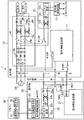
図1は、本発明の実施形態にかかる空気調和装置(1)の電装系統のブロック図である。空気調和装置(1)は、図1に示すように、室外機(10)、室内機(20)、及びリモコン(30)を備えている。なお、図示は省略するが、室外機(10)は、電動圧縮機、室外熱交換器、室外ファン、膨張弁などの機器が設けられ、室内機(20)には、室内熱交換器、室内ファンなどの機器が設けられている。空気調和装置(1)では、これらの機器によって、冷凍サイクルを行う冷媒回路(図示は省略)が構成されている。
<< Embodiment of the Invention >>
<overall structure>
FIG. 1 is a block diagram of an electrical system of an air conditioner (1) according to an embodiment of the present invention. As shown in FIG. 1, the air conditioner (1) includes an outdoor unit (10), an indoor unit (20), and a remote controller (30). Although not shown, the outdoor unit (10) is provided with devices such as an electric compressor, an outdoor heat exchanger, an outdoor fan, and an expansion valve. The indoor unit (20) includes an indoor heat exchanger, Equipment such as a fan is provided. In the air conditioning apparatus (1), these devices constitute a refrigerant circuit (not shown) that performs a refrigeration cycle.
空気調和装置(1)では、室外機(10)で、商用交流電源(50)から交流(この例では200Vの三相交流)を受電して、室外機(10)内の回路や前記電動圧縮機の電力として用いる他、その三相交流の2相分を室内機(20)に給電するようになっている。また、室外機(10)と室内機(20)との間では、室内機(20)側から室外機(10)を制御するため等の目的で、信号の通信を行うようになっている。そのため、空気調和装置(1)では、商用交流電源(50)(以下、交流電源と言う)からの交流電力を送電する電力配線(L)と、前記信号を伝送する信号線(S)と、前記交流電力の送電と前記信号の伝送に共用する共通線(N)との3線(内外配線)が室外機(10)と室内機(20)との間に設けられている。 In the air conditioner (1), the outdoor unit (10) receives AC (three-phase AC of 200 V in this example) from the commercial AC power source (50), and the circuit in the outdoor unit (10) or the electric compression In addition to being used as power for the machine, the two-phase part of the three-phase alternating current is fed to the indoor unit (20). In addition, signal communication is performed between the outdoor unit (10) and the indoor unit (20) for the purpose of controlling the outdoor unit (10) from the indoor unit (20) side. Therefore, in the air conditioner (1), power wiring (L) for transmitting AC power from a commercial AC power supply (50) (hereinafter referred to as AC power supply), a signal line (S) for transmitting the signal, Three lines (internal / external wiring) of the common line (N) shared for transmission of the AC power and transmission of the signal are provided between the outdoor unit (10) and the indoor unit (20).
〈室外機(10)〉
室外機(10)は、電装系統として、第1室外側電源回路(14)、第2室外側電源回路(12)、室外機伝送回路(11)、室外側制御回路(13)、リレー(K13R,K14R,K15R)を備えている。
<Outdoor unit (10)>
The outdoor unit (10) has, as an electrical system, a first outdoor power circuit (14), a second outdoor power circuit (12), an outdoor unit transmission circuit (11), an outdoor control circuit (13), a relay (K13R , K14R, K15R).
−第1室外側電源回路(14)−
第1室外側電源回路(14)は、交流電源(50)から受電した3相交流を直流に変換し、いわゆるインテリジェントパワーモジュール(以下、IPMと称する)や室外ファンモータに供給する。なお、IPMは、入力された直流を所定の周波数及び電圧の交流に変換し、前記電動圧縮機のモータに給電する。第1室外側電源回路(14)は、ノイズフィルタ(14a)、2つのメインリレー(14b)、2つのダイオードブリッジ回路(14c)、リアクトル(14d)、及び平滑コンデンサ(14e)を備えている。
-First outdoor power circuit (14)-
The first outdoor power supply circuit (14) converts the three-phase alternating current received from the alternating current power supply (50) into direct current, and supplies it to a so-called intelligent power module (hereinafter referred to as IPM) or an outdoor fan motor. The IPM converts the input direct current into alternating current having a predetermined frequency and voltage, and supplies power to the motor of the electric compressor. The first outdoor power supply circuit (14) includes a noise filter (14a), two main relays (14b), two diode bridge circuits (14c), a reactor (14d), and a smoothing capacitor (14e).
ノイズフィルタ(14a)は、コンデンサとコイルで形成されている。2つのメインリレー(14b)は、前記三相交流のR相、T相の供給ラインにそれぞれ設けられている。これらのメインリレー(14b)は、いわゆるA接点リレーで構成されている。2つのダイオードブリッジ回路(14c)のうち、一方は、前記三相交流のR相及びS相を入力とし、もう一方は、前記三相交流のS相及びT相を入力とし、入力された交流をそれぞれ全波整流する。これらのダイオードブリッジ回路(14c)の出力は、リアクトル(14d)を介して平滑コンデンサ(14e)に入力され、平滑コンデンサ(14e)で平滑化される。平滑コンデンサ(14e)で平滑化された直流は、前記IPMや室外ファンモータに供給される。 The noise filter (14a) is formed of a capacitor and a coil. The two main relays (14b) are respectively provided in the three-phase AC R-phase and T-phase supply lines. These main relays (14b) are so-called A contact relays. Of the two diode bridge circuits (14c), one inputs the R phase and S phase of the three-phase AC and the other inputs the S phase and T phase of the three-phase AC and inputs the AC Is full-wave rectified. The outputs of these diode bridge circuits (14c) are input to the smoothing capacitor (14e) via the reactor (14d) and smoothed by the smoothing capacitor (14e). The direct current smoothed by the smoothing capacitor (14e) is supplied to the IPM and the outdoor fan motor.
−第2室外側電源回路(12)−
第2室外側電源回路(12)は、前記三相交流のR相及びS相の2相を直流(この例では5V)に変換し、室外側制御回路(13)に供給する。この第2室外側電源回路(12)は、ダイオードブリッジ回路(12a)、平滑コンデンサ(12b)、及びスイッチング電源(12c)を備えている。ダイオードブリッジ回路(12a)は、一方の入力が、後述するリレー(K13R)に接続され、もう一方の入力が、前記三相交流のS相に接続されている。ダイオードブリッジ回路(12a)の出力は、平滑コンデンサ(12b)で平滑化された後に、スイッチング電源(12c)に入力されている。スイッチング電源(12c)は、入力された直流電圧を所定の電圧(5V)に変換して室外側制御回路(13)に出力する。
-Second outdoor power circuit (12)-
The second outdoor power supply circuit (12) converts the two phases of the three-phase alternating current R phase and S phase into direct current (5 V in this example) and supplies it to the outdoor control circuit (13). The second outdoor power supply circuit (12) includes a diode bridge circuit (12a), a smoothing capacitor (12b), and a switching power supply (12c). The diode bridge circuit (12a) has one input connected to a relay (K13R), which will be described later, and the other input connected to the S phase of the three-phase alternating current. The output of the diode bridge circuit (12a) is smoothed by the smoothing capacitor (12b) and then input to the switching power supply (12c). The switching power supply (12c) converts the input DC voltage into a predetermined voltage (5V) and outputs it to the outdoor control circuit (13).
−室外機伝送回路(11)−
室外機伝送回路(11)は、室内機伝送回路(21)との間で信号の通信を行う。この通信では、信号線(S)と共通線(N)との間の電位差に基づいて、2値のデジタル信号の通信を行う。室外機伝送回路(11)内の通信回路(図示省略)は、一端が共通線(N)に接続され、通信回路の他端はリレー(K14R)を介して信号線(S)に接続されている。
-Outdoor unit transmission circuit (11)-
The outdoor unit transmission circuit (11) performs signal communication with the indoor unit transmission circuit (21). In this communication, binary digital signals are communicated based on the potential difference between the signal line (S) and the common line (N). The communication circuit (not shown) in the outdoor unit transmission circuit (11) has one end connected to the common line (N) and the other end connected to the signal line (S) via the relay (K14R). Yes.
−リレー(K13R)−
リレー(K13R)は、第2室外側電源回路(12)への交流供給の経路を切り替えるリレーである。リレー(K13R)は、いわゆるC接点リレーで構成されている。リレー(K13R)の切換え(コイルへの通電の有無)は、室外側制御回路(13)が制御する。
−Relay (K13R) −
The relay (K13R) is a relay that switches the AC supply path to the second outdoor power supply circuit (12). The relay (K13R) is a so-called C contact relay. The outdoor control circuit (13) controls switching of the relay (K13R) (whether or not the coil is energized).
このリレー(K13R)の可動接点は、ダイオードブリッジ回路(12a)の入力に接続されている。また、ノーマルクローズ接点は、信号線(S)に接続され、ノーマルオープン接点は、前記三相交流のR相に接続されている。すなわち、リレー(K13R)のコイルに通電されていない場合は、ノーマルクローズ接点と可動接点とが接続されて、ダイオードブリッジ回路(12a)の一方の入力は信号線(S)に接続される。リレー(K13R)のコイルに通電されると、可動接点とノーマルオープン接点とが接続されて、第2室外側電源回路(12)のダイオードブリッジ回路(12a)に交流が入力される状態になる。 The movable contact of this relay (K13R) is connected to the input of the diode bridge circuit (12a). The normally closed contact is connected to the signal line (S), and the normally open contact is connected to the R phase of the three-phase alternating current. That is, when the coil of the relay (K13R) is not energized, the normally closed contact and the movable contact are connected, and one input of the diode bridge circuit (12a) is connected to the signal line (S). When the coil of the relay (K13R) is energized, the movable contact and the normally open contact are connected and AC is input to the diode bridge circuit (12a) of the second outdoor power supply circuit (12).
−リレー(K14R)−
リレー(K14R)は、信号線(S)と室外機伝送回路(11)との接続及び非接続を切り替えるリレーである。リレー(K14R)は、いわゆるA接点リレーで構成されている。リレー(K14R)のオンオフは、室外側制御回路(13)が制御する。
−Relay (K14R) −
The relay (K14R) is a relay that switches connection and disconnection between the signal line (S) and the outdoor unit transmission circuit (11). The relay (K14R) is a so-called A contact relay. The outdoor control circuit (13) controls on / off of the relay (K14R).
−リレー(K15R)−
リレー(K15R)は、室外機伝送回路(11)への電力供給の有無を切り替えるリレーである。リレー(K15R)は、いわゆるA接点リレーで構成されている。リレー(K15R)のオンオフは、室外側制御回路(13)が制御する。
−Relay (K15R) −
A relay (K15R) is a relay which switches the presence or absence of the electric power supply to an outdoor unit transmission circuit (11). The relay (K15R) is a so-called A contact relay. The outdoor control circuit (13) controls on / off of the relay (K15R).
−室外側制御回路(13)−
室外側制御回路(13)は、マイクロコンピュータと、それを動作させるプログラムを格納したメモリーを含んでいる(図示は省略)。室外側制御回路(13)は、例えば室外機伝送回路(11)が室内機伝送回路(21)から受信した信号に応じて前記電動圧縮機等の制御を行う他、室外機(10)の起動時の制御も行う。室外側制御回路(13)は、空気調和装置(1)がサスペンド状態の場合には、電力供給が断たれて動作を停止する。
−Outdoor control circuit (13) −
The outdoor control circuit (13) includes a microcomputer and a memory storing a program for operating the microcomputer (not shown). The outdoor control circuit (13) controls, for example, the electric compressor according to the signal received by the outdoor unit transmission circuit (11) from the indoor unit transmission circuit (21), and activates the outdoor unit (10). Also controls the time. When the air conditioner (1) is in the suspended state, the outdoor side control circuit (13) stops operating because the power supply is cut off.
〈室内機(20)〉
室内機(20)は、電装系統として、室内側電源回路(22)、室内機伝送回路(21)、室内側制御回路(23)、リレー(K2R)、第1ダイオード(D1)、及び第2ダイオード(D2)を備えている。
<Indoor unit (20)>
The indoor unit (20) includes, as an electrical system, an indoor power supply circuit (22), an indoor unit transmission circuit (21), an indoor control circuit (23), a relay (K2R), a first diode (D1), and a second A diode (D2) is provided.
−室内側電源回路(22)−
室内側電源回路(22)は、電力配線(L)及び共通線(N)を介して交流電源(50)から供給された交流を直流(この例では5Vの直流)に変換し、室内側制御回路(23)に供給する。この室内側電源回路(22)は、ノイズフィルタ(22a)、ダイオードブリッジ回路(22b)、平滑コンデンサ(22c)、及びスイッチング電源(22d)を備えている。ノイズフィルタ(22a)は2つのコイルで形成されている。ダイオードブリッジ回路(22b)は、ノイズフィルタ(22a)を介して電力配線(L)及び共通線(N)から入力された交流を全波整流する。平滑コンデンサ(22c)は、例えば電解コンデンサで形成され、ダイオードブリッジ回路(22b)の出力を平滑化する。スイッチング電源(22d)は、平滑コンデンサ(22c)が平滑化した直流を所定の電圧(5V)に変換して室内側制御回路(23)に出力する。
-Indoor power circuit (22)-
The indoor side power supply circuit (22) converts the alternating current supplied from the alternating current power source (50) through the power wiring (L) and the common line (N) into direct current (in this example, direct current of 5V), and controls the indoor side control. Supply to circuit (23). The indoor power supply circuit (22) includes a noise filter (22a), a diode bridge circuit (22b), a smoothing capacitor (22c), and a switching power supply (22d). The noise filter (22a) is formed of two coils. The diode bridge circuit (22b) performs full-wave rectification on the alternating current input from the power wiring (L) and the common line (N) via the noise filter (22a). The smoothing capacitor (22c) is formed of, for example, an electrolytic capacitor, and smoothes the output of the diode bridge circuit (22b). The switching power supply (22d) converts the direct current smoothed by the smoothing capacitor (22c) into a predetermined voltage (5V) and outputs it to the indoor control circuit (23).
−室内機伝送回路(21)−
室内機伝送回路(21)は、既述の通り、室外機伝送回路(11)との間で信号の通信を行う。この通信では、信号線(S)と共通線(N)との間の電位差に基づいて、デジタル信号の通信を行うので、室内機伝送回路(21)の通信回路の一端は、第2ダイオード(D2)を介して信号線(S)に接続され、通信回路の他端は共通線(N)に接続されている。
-Indoor unit transmission circuit (21)-
As described above, the indoor unit transmission circuit (21) performs signal communication with the outdoor unit transmission circuit (11). In this communication, since digital signal communication is performed based on the potential difference between the signal line (S) and the common line (N), one end of the communication circuit of the indoor unit transmission circuit (21) is connected to the second diode ( D2) is connected to the signal line (S), and the other end of the communication circuit is connected to the common line (N).
−リレー(K2R)、第1及び第2ダイオード(D1,D2)−
リレー(K2R)は、いわゆるA接点リレーで構成されている。リレー(K2R)と第1ダイオード(D1)は、室内機(20)内に設けられ、電力配線(L)と信号線(S)との間に直列接続されている。リレー(K2R)は、電力配線(L)と信号線(S)間のオンオフを切り替えるスイッチとして機能する。リレー(K2R)のオンオフは、室内側制御回路(23)が制御する。第1ダイオード(D1)は、室内機伝送回路(21)へ流入する方向の交流電流を阻止する。第2ダイオード(D2)は、室内機伝送回路(21)から流出する方向の交流電流を阻止する。
-Relay (K2R), first and second diodes (D1, D2)-
The relay (K2R) is a so-called A contact relay. The relay (K2R) and the first diode (D1) are provided in the indoor unit (20), and are connected in series between the power wiring (L) and the signal line (S). The relay (K2R) functions as a switch for switching on and off between the power wiring (L) and the signal line (S). The indoor control circuit (23) controls the on / off of the relay (K2R). The first diode (D1) blocks an alternating current flowing in the direction into the indoor unit transmission circuit (21). The second diode (D2) blocks an alternating current flowing in the direction from the indoor unit transmission circuit (21).
−室内側制御回路(23)−
室内側制御回路(23)は、マイクロコンピュータと、それを動作させるプログラムを格納したメモリーとを有し(図示省略)、室内側電源回路(22)から受電して、空気調和装置(1)の運転状態を制御するものである。この室内側制御回路(23)は、I/F回路(24)と指令部(25)とを備えている。
-Indoor control circuit (23)-
The indoor side control circuit (23) includes a microcomputer and a memory storing a program for operating the microcomputer (not shown). The indoor side control circuit (23) receives power from the indoor side power supply circuit (22) and It controls the operating state. The indoor control circuit (23) includes an I / F circuit (24) and a command unit (25).
−I/F回路(24)−
I/F回路(24)は、リモコン(30)に接続されており、リモコン(30)との間で信号を送受信する。
-I / F circuit (24)-
The I / F circuit (24) is connected to the remote controller (30), and transmits and receives signals to and from the remote controller (30).
図2に示すように、指令部(25)は、人検知センサ(26)と外部機器制御部(27)に接続されている。 As shown in FIG. 2, the command unit (25) is connected to the human detection sensor (26) and the external device control unit (27).
−人検知センサ(26)−
人検知センサ(26)は、赤外線センサであって、放射される赤外線のエネルギー変動によって、室内における人の有無を検知する。人検知センサ(26)は、室内機(20)に設置され、人検知センサ(26)から下方へ所定の角度で拡がる円錐状の領域に対して、検知可能に構成されている。
-Human detection sensor (26)-
The human detection sensor (26) is an infrared sensor, and detects the presence or absence of a person in the room based on the energy fluctuation of the emitted infrared light. The human detection sensor (26) is installed in the indoor unit (20), and is configured to be able to detect a conical region extending downward from the human detection sensor (26) at a predetermined angle.
−指令部(25)−
指令部(25)は、人検知センサ(26)の検知信号を入力して、室内の人の有無を判定し、その判定結果を外部機器制御部(27)へ出力する。具体的に、指令部(25)では、人が存在すると判定されると存在信号が出力され、人が不在であると判定されると不在信号が出力される。さらに、指令部(25)では、運転状態中に外部機器制御部(27)へ運転信号が出力され、サスペンド状態中に外部機器制御部(27)へ停止信号が出力される。
−Command section (25) −
The command unit (25) receives a detection signal from the human detection sensor (26), determines the presence / absence of a person in the room, and outputs the determination result to the external device control unit (27). Specifically, the command unit (25) outputs a presence signal when it is determined that a person is present, and outputs a presence signal when it is determined that a person is absent. Further, the command unit (25) outputs an operation signal to the external device control unit (27) during the operation state, and outputs a stop signal to the external device control unit (27) during the suspended state.
−外部機器制御部(27)−
外部機器制御部(27)は、指令部(25)から出力される信号(存在信号、不在信号、運転信号、停止信号)を入力することで、外部機器をオンオフ制御する。外部機器制御部(27)は、外部機器(この例では照明装置)が接続可能な接続端子(27a)と、接続端子(27a)に接続されたリレー(27b)を有するスイッチング部(27c)を備えている。外部機器制御部(27)では、外部機器をオンするための信号(存在信号、運転信号)を入力することで、スイッチング部(27c)のリレー(27b)がオンされ、その結果、外部機器がオンされる。外部機器制御部(27)では、外部機器をオフするための信号(不在信号、停止信号)を入力することで、スイッチング部(27c)のリレー(27b)がオフされ、その結果、外部機器がオフされる。この外部機器制御部(27)と指令部(25)は、人検知センサ(26)の検知結果に基づいて外部機器を制御する制御部(28)を構成している。尚、外部機器制御部(27)は、室内側制御回路(23)と同じ基板上に設けても構わないし、室内側制御回路(23)とは別の基板に設けることで、外部機器制御部(27)を外部接続できるようにしても構わない。
-External device control unit (27)-
The external device control unit (27) performs on / off control of the external device by inputting the signals (presence signal, absence signal, operation signal, stop signal) output from the command unit (25). The external device control unit (27) includes a switching terminal (27c) having a connection terminal (27a) to which an external device (in this example, a lighting device) can be connected and a relay (27b) connected to the connection terminal (27a). I have. In the external device control unit (27), by inputting a signal (existence signal, operation signal) for turning on the external device, the relay (27b) of the switching unit (27c) is turned on. Turned on. In the external device control unit (27), by inputting a signal for turning off the external device (absence signal, stop signal), the relay (27b) of the switching unit (27c) is turned off. Turned off. The external device control unit (27) and the command unit (25) constitute a control unit (28) that controls the external device based on the detection result of the human detection sensor (26). The external device control unit (27) may be provided on the same board as the indoor side control circuit (23), or may be provided on a different board from the indoor side control circuit (23). (27) may be externally connected.
〈リモコン(30)〉
図1に示すように、リモコン(30)は、いわゆるワイヤードリモコンであって、伝送線を介して室内機(20)に接続されている。このリモコン(30)は、通信部(31)と設定部(32)を備えている。
<Remote control (30)>
As shown in FIG. 1, the remote controller (30) is a so-called wired remote controller, and is connected to the indoor unit (20) via a transmission line. The remote control (30) includes a communication unit (31) and a setting unit (32).
−通信部(31)−
通信部(31)は、伝送線に接続され、I/F回路(24)との間で信号を送受信する。
−Communication Department (31) −
The communication unit (31) is connected to the transmission line and transmits / receives a signal to / from the I / F circuit (24).
−設定部(32)−
設定部(32)では、外部機器の制御モードがユーザによって設定される。外部機器の制御モードには、連動モードと非連動モードがある。連動モードとは、運転中(運転状態)において、人が在室する時に外部機器をオンにし、人が不在の時に外部機器をオフにする一方、運転停止中(サスペンド状態)において、室内の人の有無に関係なく外部機器をオフにするものである。非連動モードとは、運転中及び運転停止中に関係なく、常に、人が在室する時に外部機器をオンにし、人が不在の時に外部機器をオフにするものである。
-Setting section (32)-
In the setting unit (32), the control mode of the external device is set by the user. The control mode of the external device includes a linked mode and a non-linked mode. In linked mode, the external device is turned on when a person is in the room while driving (driving state), and the external device is turned off when the person is absent. The external device is turned off regardless of the presence or absence. In the non-interlocking mode, the external device is always turned on when a person is present and is turned off when a person is absent, regardless of whether the operation is in progress or stopped.
〈空気調和装置(1)の動作〉
図3は、空気調和装置(1)の状態遷移図である。空気調和装置(1)は、以下に説明するサスペンド状態、充電状態、ウエイト状態、及び運転状態の4つの状態を遷移する。
<Operation of air conditioner (1)>
FIG. 3 is a state transition diagram of the air conditioner (1). The air conditioner (1) transitions between four states: a suspended state, a charged state, a wait state, and an operating state, which will be described below.
(1)サスペンド状態
サスペンド状態とは、本発明に係る待機状態であり、室内機(20)には電力が供給され、室外機(10)には電力が供給されていない状態である。
(1) Suspended state The suspended state is a standby state according to the present invention, in which power is supplied to the indoor unit (20) and power is not supplied to the outdoor unit (10).
本実施形態のサスペンド状態は、一例として、空気調和装置(1)全体として消費電力が最小になる状態となっている。具体的に、本実施形態のサスペンド状態では、室外機(10)は電力を受電してそれを室内機(20)へ供給はするが、内部の各回路や電動圧縮機などには電力が供給されていない状態である。このように、サスペンド状態では、室外機(10)の各回路への電力供給が断たれ、待機電力の低減を図ることができる。 As an example, the suspended state of the present embodiment is a state in which the power consumption of the entire air conditioner (1) is minimized. Specifically, in the suspended state of this embodiment, the outdoor unit (10) receives power and supplies it to the indoor unit (20), but power is supplied to each internal circuit, electric compressor, and the like. It is a state that has not been done. Thus, in the suspended state, power supply to each circuit of the outdoor unit (10) is cut off, and standby power can be reduced.
一方、室内機(20)は、消費電力が最小となる状態であり、本実施形態では、人検知センサ(26)、指令部(25)、外部機器制御部(27)、及びリモコン(30)からの信号受信に関わる部分は、室内側電源回路(22)から電力を受けて動作している。 On the other hand, the indoor unit (20) is in a state where power consumption is minimized. In the present embodiment, the human detection sensor (26), the command unit (25), the external device control unit (27), and the remote control (30) The part related to the signal reception from is operated by receiving power from the indoor power supply circuit (22).
リモコン(30)は、消費電力が最小となる状態であり、ユーザーによる運転操作の受け付けが可能である状態である。なお、室内機(20)およびリモコン(30)の消費電力(待機電力)の程度はこれに限らない。 The remote control (30) is in a state where the power consumption is minimized, and the user can accept driving operations. The degree of power consumption (standby power) of the indoor unit (20) and the remote control (30) is not limited to this.
(2)充電状態
充電状態とは、室外機(10)では、第2室外側電源回路(12)に充電が開始され、室外機伝送回路(11)と室内機伝送回路(21)の間の信号伝送が開始されるまでの期間の状態をいう。
(2) Charging state In the outdoor unit (10), charging is started in the second outdoor power supply circuit (12), and between the outdoor unit transmission circuit (11) and the indoor unit transmission circuit (21). This refers to the state of the period until signal transmission is started.
室内機(20)及びリモコン(30)の電力消費は、サスペンド状態と同様である。 The power consumption of the indoor unit (20) and the remote control (30) is the same as in the suspended state.
(3)ウエイト状態
ウエイト状態とは、運転開始時には上記充電状態を抜けた状態であり、運転停止時には運転状態(後述)から遷移する状態であり、何れも、室外機(10)が、即時、運転状態(後述)へ移行可能な状態をいう。ウエイト状態では、室外機伝送回路(11)および室外側制御回路(13)の動作も可能である。特に、運転停止時のウエイト状態(運転状態から遷移するウエイト状態)は、電動圧縮機における冷媒圧力を均圧させるためや、運転開始と運転停止を繰り返すスクジュール運転が設定されている場合などのために設けられている。
(3) Wait state The wait state is a state in which the above charging state is exited at the start of operation, and a transition from the operation state (described later) when the operation is stopped. In both cases, the outdoor unit (10) This refers to a state that can be shifted to an operating state (described later). In the weight state, the operation of the outdoor unit transmission circuit (11) and the outdoor control circuit (13) is also possible. In particular, the weight state at the time of operation stop (weight state that transitions from the operation state) is used to equalize the refrigerant pressure in the electric compressor, or when the scule operation that repeats the operation start and operation stop is set. It is provided for.
尚、室内機(20)及びリモコン(30)の電力消費は、充電状態と同様である。 Note that the power consumption of the indoor unit (20) and the remote controller (30) is the same as in the charged state.
(4)運転状態
運転状態とは、第1室外側電源回路(14)からIPM及びファンモータに電力供給されて、電動圧縮機や室外ファンを運転可能、若しくは運転している状態をいう。
(4) Operational state The operational state refers to a state where electric power is supplied from the first outdoor power supply circuit (14) to the IPM and the fan motor, and the electric compressor and the outdoor fan can be operated or are operating.
リモコン(30)の電力消費は、充電状態と同様である。一方、室内機(20)の電力消費は、室内ファン等が運転状態となるため、前記の各状態よりも増加する。 The power consumption of the remote control (30) is the same as in the charged state. On the other hand, the power consumption of the indoor unit (20) is higher than in each of the above states because the indoor fan or the like is in an operating state.
−運転開始動作−
空気調和装置(1)の運転開始動作では、サスペンド状態から、充電状態、ウェイト状態、運転状態の順に状態が移行する(図3の実線矢印)。以下、サスペンド状態から運転状態までの動作を順に説明する。
-Operation start operation-
In the operation start operation of the air conditioner (1), the state transitions from the suspended state to the charged state, the wait state, and the operating state (solid arrow in FIG. 3). Hereinafter, operations from the suspended state to the operating state will be described in order.
<サスペンド状態における電装系統>
まず、サスペンド状態における電装系統の状態を説明する。図1は、サスペンド状態におけるリレーの状態を示している。
<Electrical system in suspended state>
First, the state of the electrical system in the suspended state will be described. FIG. 1 shows the state of the relay in the suspended state.
室外機(10)では、メインリレー(14b)がオフ状態であり、第1室外側電源回路(14)からIPM及び室外ファンモータへ電力が供給されない。また、リレー(K14R)及びリレー(K15R)はオフ状態であり、室外機伝送回路(11)は、信号線(S)との接続が断たれるとともに、電力の供給も断たれている。また、リレー(K13R)は、ノーマルクローズ接点と可動接点とが接続された状態であり、第2室外側電源回路(12)のダイオードブリッジ回路(12a)は、一方の入力が信号線(S)に接続されている。この状態では、第2室外側電源回路(12)には通電されず、室外側制御回路(13)への給電も行われない。このように、室外機(10)は、電力供給が遮断されている。 In the outdoor unit (10), the main relay (14b) is in an off state, and power is not supplied from the first outdoor power supply circuit (14) to the IPM and the outdoor fan motor. In addition, the relay (K14R) and the relay (K15R) are in an off state, and the outdoor unit transmission circuit (11) is disconnected from the signal line (S) and also supplied with power. The relay (K13R) is a state in which the normally closed contact and the movable contact are connected. The diode bridge circuit (12a) of the second outdoor power supply circuit (12) has one input as a signal line (S). It is connected to the. In this state, the second outdoor power supply circuit (12) is not energized, and no power is supplied to the outdoor control circuit (13). Thus, the outdoor unit (10) is shut off from the power supply.
室内機(20)では、リレー(K2R)がオフ状態であり、信号線(S)と電力配線(L)とが電気的に非接続状態である。室内機(20)では、人検知センサ(26)、指令部(25)、外部機器制御部(27)、及びリモコン(30)からの信号受信に関わる部分は、室内側電源回路(22)から電力を受けて動作している。 In the indoor unit (20), the relay (K2R) is in the off state, and the signal line (S) and the power wiring (L) are electrically disconnected. In the indoor unit (20), the person detection sensor (26), the command unit (25), the external device control unit (27), and the part related to signal reception from the remote control (30) are from the indoor side power supply circuit (22). Operating with power.
〈サスペンド状態から充電状態への移行〉
図4は、第2室外側電源回路(12)の平滑コンデンサ(12b)に充電される回路が形成された時点の各リレーの状態を示す図である。また、図5は、充電状態への移行が完了した後の各リレーの状態を示す図である。
<Transition from suspended state to charged state>
FIG. 4 is a diagram showing the state of each relay at the time when a circuit for charging the smoothing capacitor (12b) of the second outdoor side power supply circuit (12) is formed. FIG. 5 is a diagram illustrating a state of each relay after the transition to the charging state is completed.
ユーザがリモコン(30)の運転ボタン(図示省略)を押すと、通信部(31)から室内機(20)へ運転開始信号が送信される。 When the user presses an operation button (not shown) on the remote controller (30), an operation start signal is transmitted from the communication unit (31) to the indoor unit (20).
室内機(20)では、I/F回路(24)が運転開始信号を受信すると、室内側制御回路(23)がリレー(K2R)をオンにする。そうすると、前記三相交流のR相から、電力配線(L)、リレー(K2R)、第1ダイオード(D1)、信号線(S)、及びリレー(K13R)を介して第2室外側電源回路(12)に到る経路が形成される。これにより、第2室外側電源回路(12)の平滑コンデンサ(12b)が充電される回路が形成される(図4参照)。 In the indoor unit (20), when the I / F circuit (24) receives the operation start signal, the indoor side control circuit (23) turns on the relay (K2R). Then, from the R phase of the three-phase alternating current, the second outdoor power supply circuit (L), the relay (K2R), the first diode (D1), the signal line (S), and the relay (K13R) are connected. The route to 12) is formed. Thereby, a circuit is formed in which the smoothing capacitor (12b) of the second outdoor power supply circuit (12) is charged (see FIG. 4).
室外機(10)では、平滑コンデンサ(12b)が充電されてスイッチング電源(12c)への入力が安定し、スイッチング電源(12c)が規定の直流電圧(この例では5V)を出力できるようになると、室外側制御回路(13)が起動する。起動した室外側制御回路(13)は、リレー(K13R)のコイルに通電させて、ノーマルオープン接点と可動接点とを接続状態とする。これにより、ダイオードブリッジ回路(12a)の一方の入力は、前記三相交流のR相に、室外機(10)内の送電経路を介して接続される。すなわち、室外側制御回路(13)は、信号線(S)を経由せずに交流電源(50)から電力供給された状態に切り換わる(図5参照)。こうして、サスペンド状態から充電状態への移行が完了する。 In the outdoor unit (10), when the smoothing capacitor (12b) is charged and the input to the switching power supply (12c) is stabilized, the switching power supply (12c) can output the specified DC voltage (5 V in this example). The outdoor control circuit (13) is activated. The activated outdoor control circuit (13) energizes the coil of the relay (K13R) to connect the normally open contact and the movable contact. Thereby, one input of the diode bridge circuit (12a) is connected to the R phase of the three-phase alternating current via the power transmission path in the outdoor unit (10). That is, the outdoor control circuit (13) switches to a state where power is supplied from the AC power supply (50) without passing through the signal line (S) (see FIG. 5). Thus, the transition from the suspended state to the charged state is completed.
〈充電状態からウエイト状態への移行〉
図6は、ウエイト状態への移行完了時における各リレーの状態を示す図である。室内機(20)では、リレー(K2R)をオンにしてから所定の時間(室外側制御回路(13)が起動するのに十分な時間)が経過した後に、リレー(K2R)をオフにする。これにより、信号線(S)を信号の送受信に使用できるようになる。
<Transition from charge state to wait state>
FIG. 6 is a diagram illustrating the state of each relay when the transition to the wait state is completed. In the indoor unit (20), the relay (K2R) is turned off after a predetermined time (a time sufficient for starting the outdoor control circuit (13)) has elapsed since the relay (K2R) was turned on. As a result, the signal line (S) can be used for signal transmission and reception.
室外機(10)では、リレー(K2R)がオフになったのを見計らって、室外側制御回路(13)は、リレー(K15R)をオンにし、室外機伝送回路(11)に電力が供給された状態にするとともに、リレー(K14R)をオンにする。これにより、室外機伝送回路(11)内の通信回路が、信号線(S)及び共通線(N)を介して室内機伝送回路(21)と接続され、室内機伝送回路(21)と通信可能な状態になる。これで、空気調和装置(1)は、前記充電状態を抜け、即時運転状態へ移行可能な状態(すなわちウエイト状態)となる。 In the outdoor unit (10), the outdoor control circuit (13) turns on the relay (K15R) and power is supplied to the outdoor unit transmission circuit (11) in anticipation of the relay (K2R) being turned off. And turn on the relay (K14R). As a result, the communication circuit in the outdoor unit transmission circuit (11) is connected to the indoor unit transmission circuit (21) via the signal line (S) and the common line (N), and communicates with the indoor unit transmission circuit (21). It becomes possible. As a result, the air conditioner (1) enters a state where it can exit the charging state and shift to the immediate operation state (that is, a wait state).
〈ウエイト状態から運転状態への移行〉
図7は、運転状態における各リレーの状態を示す図である。ウエイト状態から運転状態への移行する際には、室外側制御回路(13)は、2つのメインリレー(14b)をオンにする。これにより、第1室外側電源回路(14)によって、IPMや室外ファンモータに電力が供給されて、電動圧縮機などが運転状態になり、例えば冷房が行われる。
<Transition from wait state to operation state>
FIG. 7 is a diagram showing the state of each relay in the operating state. When shifting from the wait state to the operation state, the outdoor control circuit (13) turns on the two main relays (14b). As a result, electric power is supplied to the IPM and the outdoor fan motor by the first outdoor power supply circuit (14), and the electric compressor and the like are put into operation, for example, cooling is performed.
−運転停止動作−
空気調和装置(1)の運転停止動作では、運転状態から、ウェイト状態、サスペンド状態の順に状態が移行する(図3の点線矢印)。以下、運転状態からサスペンド状態までの動作を順に説明する。
-Stop operation-
In the operation stop operation of the air conditioner (1), the state shifts from the operation state to the wait state and the suspend state (dotted arrow in FIG. 3). Hereinafter, operations from the operating state to the suspended state will be described in order.
<運転状態からウエイト状態への移行>
運転状態中に、ユーザーがリモコン(30)の運転ボタンを押すと、リモコン(30)は室内機(20)へ運転停止信号を送信し、その後、室内機(20)は室外機(10)へ運転停止信号を送信する。
<Transition from operating state to wait state>
When the user presses the operation button on the remote control (30) during operation, the remote control (30) sends an operation stop signal to the indoor unit (20), and then the indoor unit (20) transfers to the outdoor unit (10). Send a stop signal.
室外機(10)では、運転停止信号を受信すると、室外側制御回路(13)が第1室外側電源回路(14)のメインリレー(14b)をオンからオフに切り換える(図6参照)。これにより、IPMや室外ファンモータへの電力供給が遮断され、電動圧縮機等が停止する。こうして、運転状態からウエイト状態への移行が完了する。 In the outdoor unit (10), when the operation stop signal is received, the outdoor control circuit (13) switches the main relay (14b) of the first outdoor power supply circuit (14) from on to off (see FIG. 6). Thereby, the power supply to the IPM and the outdoor fan motor is cut off, and the electric compressor and the like are stopped. Thus, the transition from the operating state to the wait state is completed.
〈ウエイト状態からサスペンド状態への移行〉
ウェイト状態では、まず、リモコン(30)が、所定時間を経過したか否かで、サスペンド状態への移行の可否を判定する。所定時間が経過すると、リモコン(30)はサスペンド状態へ移行可能と判定する。その後、リモコン(30)は室内機(20)へ遮断要求信号を送信し、室内機(20)は室外機(10)へ遮断要求信号を送信する。
<Transition from wait state to suspend state>
In the wait state, first, the remote controller (30) determines whether or not it is possible to shift to the suspend state based on whether or not a predetermined time has elapsed. When the predetermined time has elapsed, the remote controller (30) determines that the transition to the suspended state is possible. Thereafter, the remote controller (30) transmits a blocking request signal to the indoor unit (20), and the indoor unit (20) transmits a blocking request signal to the outdoor unit (10).
室外機(10)では、室外機伝送回路(11)が遮断要求信号を受信すると、室外側制御回路(13)が、リレー(K14R)とリレー(K15R)をオフにする。さらに、室外側制御回路(13)がリレー(K13R)のノーマルクローズ接点と可動接点とが接続された状態にすることで、第2室外側電源回路(12)への電力供給が遮断される(図1参照)。こうして、サスペンド状態への移行が完了する。 In the outdoor unit (10), when the outdoor unit transmission circuit (11) receives the cutoff request signal, the outdoor side control circuit (13) turns off the relay (K14R) and the relay (K15R). Furthermore, when the outdoor control circuit (13) sets the normally closed contact and the movable contact of the relay (K13R) to be connected, the power supply to the second outdoor power supply circuit (12) is cut off ( (See FIG. 1). Thus, the transition to the suspended state is completed.
−外部機器の制御動作−
本実施形態の空気調和装置(1)では、リモコン(30)の設定部(32)に外部機器の制御モードが設定される。ユーザは、連動モードと非連動モードの内、何れかを選択して設定する。
-Control operation of external devices-
In the air conditioner (1) of the present embodiment, the control mode of the external device is set in the setting unit (32) of the remote controller (30). The user selects and sets one of the linked mode and the non-linked mode.
<連動モード設定時>
連動モードが設定された場合は、運転状態中に指令部(25)から外部機器制御部(27)へ運転信号が出力され、サスペンド状態中に指令部(25)から外部機器制御部(27)へ停止信号が出力される。
<When linked mode is set>
When the interlock mode is set, an operation signal is output from the command unit (25) to the external device control unit (27) during the operation state, and from the command unit (25) to the external device control unit (27) during the suspend state. A stop signal is output.
具体的に、空気調和装置(1)の運転開始動作が行われて運転状態へ移行すると、指令部(25)から外部機器制御部(27)へ運転信号が出力される。外部機器制御部(27)では、この運転信号によってリレー(27b)がオンされ、その結果、外部機器がオンされる。 Specifically, when the operation start operation of the air conditioner (1) is performed and the operation state is shifted to, the operation signal is output from the command unit (25) to the external device control unit (27). In the external device control unit (27), the relay (27b) is turned on by this operation signal, and as a result, the external device is turned on.
一方、空気調和装置(1)の運転停止動作が行われてサスペンド状態へ移行すると、指令部(25)から外部機器制御部(27)へ停止信号が出力される。外部機器制御部(27)では、この停止信号によってリレー(27b)がオフされ、その結果、外部機器がオフされる。 On the other hand, when the operation stop operation of the air conditioner (1) is performed to shift to the suspended state, a stop signal is output from the command unit (25) to the external device control unit (27). In the external device control unit (27), the relay (27b) is turned off by this stop signal, and as a result, the external device is turned off.
次に、人検知センサ(26)による外部機器の制御動作について説明する。 Next, an external device control operation by the human detection sensor (26) will be described.
運転状態中に、人検知センサ(26)によって人の有無が検知されると、その検知信号が指令部(25)へ入力される。指令部(25)では、その検知信号に基づいて、人の有無が判定される。そして、人が存在すると判定された場合は、指令部(25)から外部機器制御部(27)へ運転信号が出力される。外部機器制御部(27)では、この運転信号によってリレー(27b)がオンされ、その結果、外部機器はオン状態を維持する。一方、人が不在であると判定された場合は、運転停止動作が開始され、やがてサスペンド状態へと移行する。そして、サスペンド状態への移行が完了すると、指令部(25)から外部機器制御部(27)へ停止信号が出力される。外部機器制御部(27)では、この停止信号によってリレー(27b)がオフされ、その結果、外部機器がオフされる。このように、運転状態中は、人検知センサ(26)の検知結果に基づいた外部機器の制御が許可された状態になる。 When the presence or absence of a person is detected by the human detection sensor (26) during the driving state, the detection signal is input to the command section (25). The command unit (25) determines the presence or absence of a person based on the detection signal. When it is determined that there is a person, an operation signal is output from the command unit (25) to the external device control unit (27). In the external device control unit (27), the relay (27b) is turned on by this operation signal, and as a result, the external device maintains the on state. On the other hand, when it is determined that no person is present, the operation for stopping the operation is started, and the state is eventually shifted to the suspended state. When the transition to the suspended state is completed, a stop signal is output from the command unit (25) to the external device control unit (27). In the external device control unit (27), the relay (27b) is turned off by this stop signal, and as a result, the external device is turned off. As described above, during the driving state, the control of the external device based on the detection result of the human detection sensor (26) is permitted.
一方、サスペンド状態中に、人検知センサ(26)によって人の有無が検知されると、その検知信号が指令部(25)に入力される。しかし、指令部(25)では、その検知信号に基づいて、人の存在の有無が判定されない。そのため、人検知センサ(26)の検知結果に基づいた外部機器の制御が拒否された状態となり、外部機器はオフ状態を維持することとなる。 On the other hand, when the presence or absence of a person is detected by the human detection sensor (26) during the suspended state, the detection signal is input to the command unit (25). However, the command unit (25) does not determine the presence or absence of a person based on the detection signal. Therefore, the control of the external device based on the detection result of the human detection sensor (26) is rejected, and the external device is maintained in the off state.
以上のように、連動モードに設定された場合、図8に示すように、運転中(運転状態中)にのみ、人の有無に応じて外部機器がオンオフされ、運転停止中(サスペンド状態中)は、外部機器は常にオフ状態となる。 As described above, when the interlock mode is set, as shown in FIG. 8, the external device is turned on / off according to the presence / absence of a person only during operation (during operation), and operation is stopped (during suspend). The external device is always off.
<非連動モード設定時>
非連動モードが設定された場合は、空気調和装置(1)の状態に関係なく、人が存在する場合に指令部(25)から外部機器制御部(27)へ存在信号が出力され、人が不在する場合に指令部(25)から外部機器制御部(27)へ不在信号が出力される。
<When non-linked mode is set>
When the non-interlocking mode is set, the presence signal is output from the command unit (25) to the external device control unit (27) when a person is present, regardless of the state of the air conditioner (1). In the absence, an absence signal is output from the command unit (25) to the external device control unit (27).
具体的に、人検知センサ(26)によって人の有無が検知されると、その検知信号が指令部(25)へ入力される。指令部(25)では、その検知信号に基づいて、人の存在の有無が判定される。そして、人が存在すると判定された場合は、指令部(25)から外部機器制御部(27)へ存在信号が出力される。外部機器制御部(27)では、この存在信号によってリレー(27b)がオンされ、その結果、外部機器はオンされる。一方、人が不在であると判定された場合は、指令部(25)から外部機器制御部(27)へ不在信号が出力される。外部機器制御部(27)では、この不在信号によってリレー(27b)がオフされ、その結果、外部機器がオフされる。このように、人検知センサ(26)の検知結果に基づいた外部機器の制御が許可された状態となる。 Specifically, when the presence or absence of a person is detected by the human detection sensor (26), the detection signal is input to the command unit (25). The command unit (25) determines the presence or absence of a person based on the detection signal. When it is determined that there is a person, a presence signal is output from the command unit (25) to the external device control unit (27). In the external device control unit (27), the relay (27b) is turned on by this presence signal, and as a result, the external device is turned on. On the other hand, when it is determined that the person is absent, an absence signal is output from the command unit (25) to the external device control unit (27). In the external device control unit (27), the relay (27b) is turned off by this absence signal, and as a result, the external device is turned off. In this manner, the control of the external device based on the detection result of the human detection sensor (26) is permitted.
以上のように、非連動モードに設定された場合、図9に示すように、空気調和装置(1)の運転中及び運転停止中に関係なく、常に、人の有無に応じて外部機器がオンオフされる。 As described above, when the non-interlocking mode is set, as shown in FIG. 9, the external device is always turned on / off according to the presence or absence of a person regardless of whether the air conditioner (1) is in operation or stopped. Is done.
〈本実施形態における効果〉
本実施形態によれば、運転中に外部機器のオンオフ制御を可能にし、運転停止中に外部機器のオンオフ制御を不可能にする連動モードとは別に、運転中に限らず運転停止中に、外部機器のオンオフ制御を可能にする非連動モードを、ユーザによって設定できるようにした。これにより、運転停止中に、人検知センサ(26)によって外部機器をオンオフ制御することができ、ユーザの利便性を向上させることができる。
<Effect in this embodiment>
According to the present embodiment, the on / off control of the external device can be performed during the operation, and the on / off control of the external device cannot be performed during the operation stop. The user can set the non-interlocking mode that enables device on / off control. As a result, the external device can be controlled on and off by the human detection sensor (26) while the operation is stopped, and the convenience for the user can be improved.
また、本実施形態によれば、運転停止動作時に、室外機(10)への電力供給が遮断されるサスペンド状態へ移行するようにした。これにより、非連動モードに設定して、運転停止中に外部機器をオンオフ制御しても、運転停止中における空気調和装置(1)全体の消費電力(待機電力)を低減させることができる。 Further, according to the present embodiment, the operation is shifted to the suspended state in which the power supply to the outdoor unit (10) is interrupted during the operation stop operation. Thereby, even if it sets to non-interlocking mode and external equipment is turned on and off during operation stop, the power consumption (standby power) of the entire air conditioner (1) during operation stop can be reduced.
また、本実施形態によれば、連動モードが設定された場合、人が退室して不在になると、外部機器だけでなく空気調和装置(1)自体も停止するようにした。これにより、退室時における空気調和装置(1)の停止し忘れを防止することができる。 Further, according to the present embodiment, when the interlock mode is set, when a person leaves and is absent, not only the external device but also the air conditioner (1) itself is stopped. Thereby, it is possible to prevent forgetting to stop the air conditioner (1) when leaving the room.
〈その他の実施形態〉
上記実施形態では、外部機器として照明装置が設置されているが、外部機器はこれに限らず、例えば、加湿器、換気装置、警報器、監視装置であっても良い。
<Other embodiments>
In the above embodiment, the lighting device is installed as the external device, but the external device is not limited to this, and may be, for example, a humidifier, a ventilator, an alarm device, or a monitoring device.
また、上記実施形態では、人が在室する場合に外部機器をオンし、人が不在の場合に外部機器をオフする制御を行っているが、逆に、人が在室する場合に外部機器をオフし、人が不在の場合に外部機器をオフする制御を行っても良い。 In the above embodiment, the control is performed so that the external device is turned on when a person is present and the external device is turned off when the person is absent. Control may be performed to turn off the external device when no person is present.
また、上記実施形態では、外部機器である照明装置をオンオフ制御している。しかし、外部機器の制御はオンオフ制御に限らず、例えば、照明装置の照度を変更する等、外部機器の出力を調整する制御であっても構わない。 Moreover, in the said embodiment, the lighting apparatus which is an external apparatus is controlled on / off. However, the control of the external device is not limited to the on / off control, and may be control for adjusting the output of the external device, for example, changing the illuminance of the lighting device.
以上説明したように、本発明は、室内の空気を調和する空気調和装置について有用である。 As described above, the present invention is useful for an air conditioner that harmonizes indoor air.
1 空気調和装置
10 室外機
20 室内機
26 人検知センサ
28 制御部
32 設定部
1 Air conditioner
10 Outdoor unit
20 Indoor unit
26 Human detection sensor
28 Control unit
32 Setting section
Claims (2)
上記室内機(20)は、上記人検知センサ(26)の検知結果に基づいて外部機器を制御する制御部(28)を有し、
運転停止時に、上記室内機(20)へ電力が供給され、且つ上記室外機(10)への電力供給が遮断される待機状態に移行可能に構成されるとともに、上記待機状態において上記人検知センサ(26)及び制御部(28)へ電力が供給されるように構成される一方、
運転中に上記制御部(28)が上記人検知センサ(26)の検知結果に基づいた外部機器の制御を許可し、待機状態を含む運転停止中に上記制御部(28)が上記人検知センサ(26)の検知結果に基づいた外部機器の制御を拒否する連動モードと、運転中及び待機状態を含む運転停止中に関係なく、常に上記制御部(28)が上記人検知センサ(26)の検知結果に基づいた外部機器の制御を許可する非連動モードとの何れかがユーザによって設定される設定部(32)を備えている
ことを特徴とする空気調和装置。 An air conditioner provided with an indoor unit (20), an outdoor unit (10), and a human detection sensor (26) that is provided in the indoor unit (20) and detects the presence or absence of an indoor person,
The indoor unit (20) includes a control unit (28) that controls an external device based on the detection result of the human detection sensor (26).
When the operation is stopped, power is supplied to the indoor unit (20) and the power supply to the outdoor unit (10) is configured to be able to shift to a standby state, and the human detection sensor in the standby state While (26) and the control unit (28) are configured to be supplied with power,
The control unit (28) permits the control of the external device based on the detection result of the human detection sensor (26) during operation, and the control unit (28) detects the human detection sensor during operation stop including a standby state. Regardless of the interlocking mode in which control of the external device based on the detection result of (26) is rejected and the operation stoppage including the operation state and the standby state, the control unit (28) is always connected to the human detection sensor (26). An air conditioner comprising a setting unit (32) in which any one of a non-interlocking mode that allows control of an external device based on a detection result is set by a user.
上記設定部(32)は、上記室内機(20)に接続されたリモコン(30)に設けられている
ことを特徴とする空気調和装置。 In claim 1,
The air conditioning apparatus, wherein the setting unit (32) is provided in a remote controller (30) connected to the indoor unit (20) .
Priority Applications (6)
| Application Number | Priority Date | Filing Date | Title |
|---|---|---|---|
| JP2012026866A JP5403083B2 (en) | 2012-02-10 | 2012-02-10 | Air conditioner |
| CN201380007561.8A CN104081132B (en) | 2012-02-10 | 2013-02-08 | Air conditioner |
| US14/375,312 US9989272B2 (en) | 2012-02-10 | 2013-02-08 | Air conditioner |
| ES13747298.1T ES2621925T3 (en) | 2012-02-10 | 2013-02-08 | Air conditioner |
| EP13747298.1A EP2806229B1 (en) | 2012-02-10 | 2013-02-08 | Air conditioner |
| PCT/JP2013/000713 WO2013118513A1 (en) | 2012-02-10 | 2013-02-08 | Air conditioner |
Applications Claiming Priority (1)
| Application Number | Priority Date | Filing Date | Title |
|---|---|---|---|
| JP2012026866A JP5403083B2 (en) | 2012-02-10 | 2012-02-10 | Air conditioner |
Publications (2)
| Publication Number | Publication Date |
|---|---|
| JP2013164189A JP2013164189A (en) | 2013-08-22 |
| JP5403083B2 true JP5403083B2 (en) | 2014-01-29 |
Family
ID=48947283
Family Applications (1)
| Application Number | Title | Priority Date | Filing Date |
|---|---|---|---|
| JP2012026866A Active JP5403083B2 (en) | 2012-02-10 | 2012-02-10 | Air conditioner |
Country Status (6)
| Country | Link |
|---|---|
| US (1) | US9989272B2 (en) |
| EP (1) | EP2806229B1 (en) |
| JP (1) | JP5403083B2 (en) |
| CN (1) | CN104081132B (en) |
| ES (1) | ES2621925T3 (en) |
| WO (1) | WO2013118513A1 (en) |
Families Citing this family (7)
| Publication number | Priority date | Publication date | Assignee | Title |
|---|---|---|---|---|
| DE112015006249T5 (en) * | 2015-03-03 | 2017-11-16 | Mitsubishi Electric Corporation | Communication system, transmitting device and receiving device |
| CN107250680B (en) * | 2015-03-27 | 2019-08-27 | 三菱电机株式会社 | Air conditioner |
| JP6674083B2 (en) * | 2015-06-19 | 2020-04-01 | シンフォニアテクノロジー株式会社 | Gas supply target device, gas supply system, and method of controlling gas supply system |
| KR101737364B1 (en) * | 2015-08-31 | 2017-05-18 | 엘지전자 주식회사 | Air conditioner including the same |
| KR101951675B1 (en) * | 2017-03-28 | 2019-02-25 | 엘지전자 주식회사 | Air conditioner having power saving function |
| JP7147147B2 (en) * | 2017-09-29 | 2022-10-05 | Toto株式会社 | remote control system |
| CN115552177A (en) * | 2020-05-18 | 2022-12-30 | 三菱电机株式会社 | Sensor power supply control system and air purifier |
Family Cites Families (8)
| Publication number | Priority date | Publication date | Assignee | Title |
|---|---|---|---|---|
| JPH05203218A (en) * | 1992-01-30 | 1993-08-10 | Mitsubishi Electric Corp | Air conditioner with lighting |
| CN1191293A (en) * | 1998-03-24 | 1998-08-26 | 吴志源 | Intelligent fuzzy logic controlling method for air conditioner |
| CN1263341C (en) * | 1999-07-13 | 2006-07-05 | 松下电器产业株式会社 | Household appliance control network system |
| JP2004150731A (en) | 2002-10-31 | 2004-05-27 | Daikin Ind Ltd | Air conditioner |
| JP4254524B2 (en) * | 2003-12-22 | 2009-04-15 | パナソニック電工株式会社 | Automatic switch with hot wire sensor |
| US20100070089A1 (en) * | 2008-09-15 | 2010-03-18 | Johnson Controls Technology Company | Hvac controller user interfaces |
| JP2010164231A (en) * | 2009-01-15 | 2010-07-29 | Fujitsu General Ltd | Air conditioner and remote control device used for the same |
| CN201628340U (en) * | 2010-02-25 | 2010-11-10 | 济南赛英立德电子科技有限公司 | Air-conditioner energy saving controller of double control modes |
-
2012
- 2012-02-10 JP JP2012026866A patent/JP5403083B2/en active Active
-
2013
- 2013-02-08 ES ES13747298.1T patent/ES2621925T3/en active Active
- 2013-02-08 US US14/375,312 patent/US9989272B2/en active Active
- 2013-02-08 EP EP13747298.1A patent/EP2806229B1/en active Active
- 2013-02-08 CN CN201380007561.8A patent/CN104081132B/en active Active
- 2013-02-08 WO PCT/JP2013/000713 patent/WO2013118513A1/en active Application Filing
Also Published As
| Publication number | Publication date |
|---|---|
| EP2806229A1 (en) | 2014-11-26 |
| EP2806229B1 (en) | 2017-03-29 |
| WO2013118513A1 (en) | 2013-08-15 |
| US20150013362A1 (en) | 2015-01-15 |
| CN104081132A (en) | 2014-10-01 |
| JP2013164189A (en) | 2013-08-22 |
| US9989272B2 (en) | 2018-06-05 |
| CN104081132B (en) | 2015-07-22 |
| EP2806229A4 (en) | 2015-11-25 |
| ES2621925T3 (en) | 2017-07-05 |
Similar Documents
| Publication | Publication Date | Title |
|---|---|---|
| JP5403083B2 (en) | Air conditioner | |
| JP5382105B2 (en) | Air conditioner | |
| JP2013137118A (en) | Air conditioning device | |
| KR20140096179A (en) | Air conditioning device | |
| JP5381252B2 (en) | Air conditioner | |
| JP2013137119A (en) | Air conditioning device | |
| WO2013099275A1 (en) | Air conditioner | |
| JP5772588B2 (en) | Air conditioner | |
| JP5804009B2 (en) | Air conditioner | |
| JP5246324B2 (en) | Air conditioner | |
| JP5655775B2 (en) | Air conditioner | |
| JP2013137113A (en) | Air conditioning device | |
| KR101596680B1 (en) | Air-conditioner and method | |
| KR102478858B1 (en) | AIR CONDITIONER | |
| WO2020194658A1 (en) | Air conditioner | |
| JP2001012782A (en) | Separate type air conditioner | |
| JP5772577B2 (en) | Air conditioner | |
| JP2013137138A (en) | Air conditioning device | |
| JP5772579B2 (en) | Air conditioner | |
| JP2015055450A (en) | Air conditioning device | |
| JP2000320866A (en) | Air conditioner | |
| JP5403144B2 (en) | Air conditioner | |
| JPH10122636A (en) | System-control method by power-source control | |
| JP2011085322A (en) | Air-conditioning auxiliary system and air-conditioning interlocking control system | |
| JP2008146452A (en) | Voltage controller |
Legal Events
| Date | Code | Title | Description |
|---|---|---|---|
| A521 | Request for written amendment filed |
Free format text: JAPANESE INTERMEDIATE CODE: A523 Effective date: 20130703 |
|
| TRDD | Decision of grant or rejection written | ||
| A01 | Written decision to grant a patent or to grant a registration (utility model) |
Free format text: JAPANESE INTERMEDIATE CODE: A01 Effective date: 20131001 |
|
| A61 | First payment of annual fees (during grant procedure) |
Free format text: JAPANESE INTERMEDIATE CODE: A61 Effective date: 20131014 |
|
| R151 | Written notification of patent or utility model registration |
Ref document number: 5403083 Country of ref document: JP Free format text: JAPANESE INTERMEDIATE CODE: R151 |