JP5402408B2 - Fixing device roller, fixing device, image forming apparatus, fixing device roller replacement aid, and fixing device roller replacement method - Google Patents
Fixing device roller, fixing device, image forming apparatus, fixing device roller replacement aid, and fixing device roller replacement method Download PDFInfo
- Publication number
- JP5402408B2 JP5402408B2 JP2009199997A JP2009199997A JP5402408B2 JP 5402408 B2 JP5402408 B2 JP 5402408B2 JP 2009199997 A JP2009199997 A JP 2009199997A JP 2009199997 A JP2009199997 A JP 2009199997A JP 5402408 B2 JP5402408 B2 JP 5402408B2
- Authority
- JP
- Japan
- Prior art keywords
- roller
- fixing device
- support unit
- guide shaft
- heating roller
- Prior art date
- Legal status (The legal status is an assumption and is not a legal conclusion. Google has not performed a legal analysis and makes no representation as to the accuracy of the status listed.)
- Active
Links
Images


Classifications
-
- G—PHYSICS
- G03—PHOTOGRAPHY; CINEMATOGRAPHY; ANALOGOUS TECHNIQUES USING WAVES OTHER THAN OPTICAL WAVES; ELECTROGRAPHY; HOLOGRAPHY
- G03G—ELECTROGRAPHY; ELECTROPHOTOGRAPHY; MAGNETOGRAPHY
- G03G21/00—Arrangements not provided for by groups G03G13/00 - G03G19/00, e.g. cleaning, elimination of residual charge
- G03G21/16—Mechanical means for facilitating the maintenance of the apparatus, e.g. modular arrangements
- G03G21/1661—Mechanical means for facilitating the maintenance of the apparatus, e.g. modular arrangements means for handling parts of the apparatus in the apparatus
- G03G21/1685—Mechanical means for facilitating the maintenance of the apparatus, e.g. modular arrangements means for handling parts of the apparatus in the apparatus for the fixing unit
-
- G—PHYSICS
- G03—PHOTOGRAPHY; CINEMATOGRAPHY; ANALOGOUS TECHNIQUES USING WAVES OTHER THAN OPTICAL WAVES; ELECTROGRAPHY; HOLOGRAPHY
- G03G—ELECTROGRAPHY; ELECTROPHOTOGRAPHY; MAGNETOGRAPHY
- G03G15/00—Apparatus for electrographic processes using a charge pattern
- G03G15/20—Apparatus for electrographic processes using a charge pattern for fixing, e.g. by using heat
- G03G15/2003—Apparatus for electrographic processes using a charge pattern for fixing, e.g. by using heat using heat
- G03G15/2014—Apparatus for electrographic processes using a charge pattern for fixing, e.g. by using heat using heat using contact heat
- G03G15/2039—Apparatus for electrographic processes using a charge pattern for fixing, e.g. by using heat using heat using contact heat with means for controlling the fixing temperature
- G03G15/2042—Apparatus for electrographic processes using a charge pattern for fixing, e.g. by using heat using heat using contact heat with means for controlling the fixing temperature specially for the axial heat partition
-
- G—PHYSICS
- G03—PHOTOGRAPHY; CINEMATOGRAPHY; ANALOGOUS TECHNIQUES USING WAVES OTHER THAN OPTICAL WAVES; ELECTROGRAPHY; HOLOGRAPHY
- G03G—ELECTROGRAPHY; ELECTROPHOTOGRAPHY; MAGNETOGRAPHY
- G03G15/00—Apparatus for electrographic processes using a charge pattern
- G03G15/20—Apparatus for electrographic processes using a charge pattern for fixing, e.g. by using heat
- G03G15/2003—Apparatus for electrographic processes using a charge pattern for fixing, e.g. by using heat using heat
- G03G15/2014—Apparatus for electrographic processes using a charge pattern for fixing, e.g. by using heat using heat using contact heat
- G03G15/2053—Structural details of heat elements, e.g. structure of roller or belt, eddy current, induction heating
-
- G—PHYSICS
- G03—PHOTOGRAPHY; CINEMATOGRAPHY; ANALOGOUS TECHNIQUES USING WAVES OTHER THAN OPTICAL WAVES; ELECTROGRAPHY; HOLOGRAPHY
- G03G—ELECTROGRAPHY; ELECTROPHOTOGRAPHY; MAGNETOGRAPHY
- G03G2221/00—Processes not provided for by group G03G2215/00, e.g. cleaning or residual charge elimination
- G03G2221/16—Mechanical means for facilitating the maintenance of the apparatus, e.g. modular arrangements and complete machine concepts
- G03G2221/1639—Mechanical means for facilitating the maintenance of the apparatus, e.g. modular arrangements and complete machine concepts for the fixing unit
Description
本発明は、例えばレーザービームプリンタなどの画像形成装置に係り、特にそれの定着装置用ローラおよびそれを備えた定着装置に関するものである。 The present invention relates to an image forming apparatus such as a laser beam printer, and more particularly to a fixing device roller and a fixing device including the same.
レーザービームプリンタや複写機などの画像形成装置の定着装置として、表面に未定着のトナー像を保持した被記録媒体を加熱ローラと加圧ローラの間で挟持して搬送しながら加熱・加圧し、トナー像を前記被記録媒体に定着する形態の定着装置が知られている。 As a fixing device of an image forming apparatus such as a laser beam printer or a copying machine, a recording medium holding an unfixed toner image on the surface is sandwiched between a heating roller and a pressure roller, and heated and pressed while being conveyed. There is known a fixing device configured to fix a toner image onto the recording medium.
加熱ローラの内部には熱源として複数本のヒータランプが設置され、一般に印刷速度の速い画像形成装置や高連量用紙をサポートしている画像形成装置になればなる程、トナー像の定着に必要な熱容量が増すため、加熱ローラを或る温度以上に維持させなければならず、定着温度はますます高温になる。 Inside the heating roller, multiple heater lamps are installed as heat sources, and the heat capacity required for fixing the toner image is generally increased as the image forming apparatus with a high printing speed or the image forming apparatus that supports high reaming paper is used. Therefore, the heating roller must be maintained above a certain temperature, and the fixing temperature becomes higher.
このように高温に維持された加熱ローラが寿命に達し、加熱ローラの交換を行なう場合、画像形成装置の稼動を止めてから、加熱ローラ自体の温度を交換作業が可能な程度まで冷ました上で、保守技術者が加熱ローラを定着装置から取り外して、新品の加熱ローラと交換するのでは、加熱ローラを冷ますのに時間がかかり、非常に作業効率が悪い。またこれにより、画像形成装置の停止時間が長くなり、画像形成装置の稼動効率が下がるだけでなく、交換保守作業にかかる費用負担も大きい。 When the heating roller maintained at such a high temperature has reached the end of its life and the heating roller is to be replaced, after the operation of the image forming device has been stopped, the temperature of the heating roller itself has been cooled to such an extent that it can be replaced. When the maintenance engineer removes the heating roller from the fixing device and replaces it with a new heating roller, it takes time to cool the heating roller, which is very inefficient. This not only lengthens the downtime of the image forming apparatus, lowers the operating efficiency of the image forming apparatus, but also increases the cost of replacement maintenance work.
近年、画像形成装置には高印刷速度、高画質、様々な種類の用紙への対応が求められており、定着装置においては、高速印刷を求める場合には、トナー像定着に必要な熱供給の敏速化を目的とした表面層をPFA(テトラフルオロエチレン・パーフルオロアルキルビニールエーテル共重合体)樹脂などで薄くコーティングした加熱ローラ、高画質を求める場合には、トナー像の定着時の潰れやにじみを最小に抑えることを目的とした表面層をシリコンゴムなどで覆った加熱ローラ、また、或る程度の画質で且つ加熱ローラの耐久性も必要である場合には、シリコンゴム層の上にPFAチューブなどで被覆した加熱ローラなどのように、数種類の加熱ローラの使用が要求されている。 In recent years, image forming apparatuses have been required to support high printing speeds, high image quality, and various types of paper. In fixing apparatuses, when high-speed printing is required, heat supply necessary for toner image fixing is required. Heat roller with a thin surface layer coated with PFA (tetrafluoroethylene / perfluoroalkyl vinyl ether copolymer) resin for the purpose of speeding up. When high image quality is required, crushing and blurring when fixing the toner image A heating roller whose surface layer is covered with silicon rubber or the like for the purpose of minimizing the temperature, and when a certain level of image quality and durability of the heating roller are required, a PFA is formed on the silicon rubber layer. Several types of heating rollers are required to be used, such as a heating roller covered with a tube.
そこで、1台の画像形成装置で求められる要求に応じるためには、その要求に合った加熱ローラに変更する必要がある。しかし、加熱ローラは、種類により多少の差はあるが基本的には熱容量が大きく、最適なトナー像定着に必要な熱量を供給するための加熱ローラの維持温度である高温状態から冷えてローラ交換が可能になるまでにかなりの時間が必要であった。 Therefore, in order to meet the demand for one image forming apparatus, it is necessary to change to a heating roller that meets the demand. However, although the heating roller has a slight difference depending on the type, it basically has a large heat capacity, and the roller is cooled from the high temperature, which is the maintenance temperature of the heating roller to supply the amount of heat necessary for optimal toner image fixing, and the roller is replaced. It took a considerable amount of time to become possible.
加熱ローラの交換に関しては、例えば後記のような特許文献1を挙げることができる。
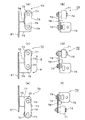
図24および図25は、この特許文献1に記載されている定着装置の一部断面図、および加熱ローラを交換するときの状態を示す斜視図である。
Regarding the replacement of the heating roller, for example,
24 and 25 are a partial cross-sectional view of the fixing device described in
図24に示すように加熱ローラ100の一端は、支承フランジ101を介してフレーム102に支承されている。支承フランジ101は軸受け103を有し、この軸受け103はセンタリング部材104とともに加熱ローラ100の開口端に嵌合されている。図示していないが、加熱ローラ100の他端も同様に軸受けを介して支承フランジに支承されている。
As shown in FIG. 24, one end of the
支承フランジ101は、蝶ネジ106を介してフレーム102に固定されている。支承フランジ101には蝶ネジ107を介して保持つめ108が固定され、この保持つめ108は加熱ローラ100の交換時に加熱ローラ100を固定する機能を有している。
The
加熱ローラ100の内側には複数本の放射器モジュール105が配置され、放射器モジュール105の一端は保持部材109を介して支承フランジ101の中央部に保持されている。図示していないが、放射器モジュール105の他端も同様に保持部材を介して間接的に支承フランジに保持されている。
A plurality of
同図に示すように放射器モジュール105を支承フランジ101の中央部に保持した状態で、放射器モジュール105の端部に設けられたコネクタ110は支承フランジ101よりも外側に突出している。支承フランジ101には加熱ローラ100の交換のためのグリップ111が一体に設けられているが、このグリップ111は支承フランジ101から突出した前記放射器モジュール105のコネクタ110を跨ぐように設けられている。
As shown in the figure, the
加熱ローラ100を交換する際には、蝶ネジ106を緩めて、図25に示すように前記グリップ111を一方の手で持ち、加熱ローラ100を支承フランジ101などと一緒にフレーム102から引き抜く。このとき加熱ローラ100がフレーム102の開口部を通過する際にフレーム102への接触を防ぐために、フレーム102の開口部外周にフェルト130を貼り付けて加熱ローラ100への傷防止を図っている。
When replacing the
この種の定着装置に用いられている加熱ローラは、直径が100mm程度、長さが500mm以上もある円筒形状のもので、それ自体でもかなりの重量がある。このような状況下において前記特許文献1に開示された定着装置では、前記グリップ111を一方の手で持ち、手袋120をした他方の手で加熱ローラ100を支えながら、加熱ローラ100を支承フランジ101などと共にフレーム102から引き抜く際に、加熱ローラ100などの重さと熱さとで抜き差し作業中の動作が不安定である。そのため加熱ローラ100の交換作業中に加熱ローラ100が例えばフレーム102などの他の部品と接触して、ローラ表面に傷を付ける危険があった。
The heating roller used in this type of fixing device has a cylindrical shape with a diameter of about 100 mm and a length of 500 mm or more, and itself has a considerable weight. Under such circumstances, in the fixing device disclosed in
このように加熱ローラ100の姿勢が不安定であり、しかも加熱ローラ100の姿勢を安定化するための補助具がないため、前記特許文献1に開示された実施形態では、交換時に加熱ローラ100に手袋120を嵌めた手を添えて行なっている。しかし、高温状態の加熱ローラ100に触れると火傷をしたり、加熱ローラ100に付着している離型剤や潤滑油などが手袋120などに付いて汚れたりするなど、操作性に問題がある。
As described above, since the posture of the
また、前記グリップ111を一方の手で持って、加熱ローラ100を支承フランジ101などと共にフレーム102から引き抜く際に、フレーム102と接触して、ローラ表面に傷を付ける危険があるため、フレーム102の開口部付近にフェルト130を貼り付けて保護している。しかし、離型剤や潤滑油が付着している加熱ローラ100を滑らせるため、フェルト130上に汚れが溜り、加熱ローラ100の表面保護としては不十分な構成である。
Also, when holding the
また加熱ローラ100の交換の度毎にフェルト130を貼り付けたり剥がしたりする作業が必要であり、そのために交換作業が煩雑になる。さらに加熱ローラ100の交換の度毎にフェルト130が汚れるから、汚れたフェルト130の処分と新しいフェルト130の準備が必要である。
Further, every time the
本発明の目的は、このような従来技術の欠点を解消し、ローラの交換が簡便にかつ安全に行える定着装置用ローラ、定着装置、画像形成装置、定着装置のローラ交換補助具、定着装置のローラ交換方法を提供することにある。 An object of the present invention is to solve such drawbacks of the prior art and to provide a roller for a fixing device, a fixing device, an image forming apparatus, a roller replacement assisting tool for the fixing device, and a fixing device that can easily and safely replace a roller. It is to provide a roller replacement method.
前記目的を達成するため、本発明の第1の手段は、加熱ローラと、その加熱ローラに対して圧接可能に設けた加圧ローラを有し、表面に未定着のトナー像を保持した被記録媒体を前記加熱ローラと加圧ローラの間で挟持・搬送しながら加熱・加圧して、前記トナー像を被記録媒体に定着する定着装置に用いられ、
前記加熱ローラおよび加圧ローラのうちの少なくとも一方のローラが当該ローラの軸方向に沿って前記定着装置から交換可能に支持される定着装置用ローラにおいて、
当該ローラの内側に摺動部材を一体に設け、
その摺動部材は、略円盤状をしており、且つ、当該ローラの交換時に当該ローラ内に挿抜されるローラ挿抜用案内シャフトを挿通する挿通穴を有し、その挿通穴の穴径は前記ローラ挿抜用案内シャフトの外径と略同寸になっていることを特徴とするものである。
In order to achieve the above object, a first means of the present invention is a recording target having a heating roller and a pressure roller provided so as to be in pressure contact with the heating roller, and holding an unfixed toner image on the surface. It is used in a fixing device for fixing the toner image on a recording medium by heating / pressing the medium while nipping / conveying the medium between the heating roller and the pressure roller,
In the fixing device roller in which at least one of the heating roller and the pressure roller is supported so as to be replaceable from the fixing device along the axial direction of the roller.
A sliding member is integrally provided inside the roller,
The sliding member has a substantially disk shape, and has an insertion hole for inserting a roller insertion / extraction guide shaft that is inserted into and extracted from the roller when the roller is replaced. The roller insertion / extraction guide shaft has substantially the same outer diameter as that of the roller insertion / extraction guide shaft .
本発明の第2の手段は前記第1の手段において、前記摺動部材が略円盤状をしており、前記ローラが熱源を内蔵するローラであって、前記熱源からの輻射熱がローラの外側に放出するのを防止する放熱防止部材を前記摺動部材が兼ねていることを特徴とするものである。 According to a second means of the present invention, in the first means, the sliding member has a substantially disk shape, the roller is a roller having a built-in heat source, and radiant heat from the heat source is on the outside of the roller. The sliding member also serves as a heat dissipation preventing member for preventing the release.
本発明の第3の手段は前記第2の手段において、前記摺動部材が当該ローラの通紙領域よりも外側に設置されていることを特徴とするものである。 A third means of the present invention is characterized in that, in the second means, the sliding member is disposed outside a sheet passing area of the roller.
本発明の第4の手段は前記第3の手段において、前記摺動部材の外径部と内径部の間に、摺動部材の外径部側よりも内径部側の方が前記ローラの開口部に近くなるように傾斜部を設けたことを特徴とするものである。 According to a fourth means of the present invention, in the third means, the opening of the roller is located between the outer diameter portion and the inner diameter portion of the sliding member on the inner diameter portion side rather than the outer diameter portion side of the sliding member. An inclined part is provided so as to be close to the part.
本発明の第5の手段は前記第1ないし4のいずれかの手段において、前記摺動部材の内径部に耐熱性樹脂層が設けられていることを特徴とするものである。 According to a fifth means of the present invention, in any one of the first to fourth means, a heat resistant resin layer is provided on an inner diameter portion of the sliding member.
本発明の第6の手段は前記第1ないし5のいずれかの手段において、前記ローラの抜き出し方向の先端部に、そのローラを抜き出す支援ユニットが着脱可能に連結される支援ユニット連結部材が設けられ、前記ローラの支援ユニット連結部材とは反対側の開口部付近に前記摺動部材が設けられていることを特徴とするものである。 According to a sixth means of the present invention, in any one of the first to fifth means, a support unit connecting member is provided at a distal end portion in the extracting direction of the roller so that a support unit for extracting the roller is detachably connected. The sliding member is provided in the vicinity of the opening of the roller opposite to the support unit connecting member.
本発明の第7の手段は前記第6の手段において、前記支援ユニット連結部材が略円盤状をしており、前記ローラが熱源を内蔵するローラであって、前記熱源からの輻射熱がローラの外側に放出するのを防止する放熱防止部材を前記支援ユニット連結部材が兼ねていることを特徴とするものである。 According to a seventh means of the present invention, in the sixth means , the support unit connecting member has a substantially disc shape, the roller is a roller having a built-in heat source, and the radiant heat from the heat source is outside the roller. The support unit connecting member also serves as a heat dissipation preventing member for preventing the heat release.
本発明の第8の手段は前記第7の手段において、前記支援ユニット連結部材が当該ローラの通紙領域よりも外側に設置されていることを特徴とするものである。 According to an eighth means of the present invention, in the seventh means, the support unit connecting member is disposed outside a sheet passing area of the roller.
本発明の第9の手段は前記第6の手段において、前記支援ユニットに設けられている挟持片部が挿通する切欠部と、前記切欠部と連通して切欠部に挿通した前記挟持片部が所定角度回転するのを許容する回転許容部と、前記回転許容部の一端部に前記挟持片部が当接して前記挟持片部の回転を停止する停止部が、前記支援ユニット連結部材に設けられていることを特徴とするものである。 According to a ninth means of the present invention, in the sixth means, a notch portion through which the holding piece portion provided in the support unit is inserted, and the holding piece portion that is communicated with the notch portion and inserted into the notch portion are provided. The support unit connecting member is provided with a rotation allowing portion that allows rotation by a predetermined angle, and a stop portion that stops the rotation of the holding piece when the holding piece comes into contact with one end of the rotation allowing portion. It is characterized by that.
本発明の第10の手段は前記第9の手段において、前記支援ユニットの固定位置を表示するマークが前記ローラの外周端部に設けられていることを特徴とするものである。 According to a tenth means of the present invention, in the ninth means, a mark for indicating a fixed position of the support unit is provided at an outer peripheral end portion of the roller.
前記目的を達成するため、本発明の第11の手段は、加熱ローラと、その加熱ローラに対して圧接可能に設けた加圧ローラを有し、表面に未定着のトナー像を保持した被記録媒体を前記加熱ローラと加圧ローラの間で挟持・搬送しながら加熱・加圧して、前記トナー像を被記録媒体に定着するとともに、
前記加熱ローラおよび加圧ローラのうちの少なくとも一方のローラが当該ローラの軸方向に沿って交換可能に支持されている定着装置において、
前記交換可能に支持されている定着装置用ローラが請求項1ないし10のいずれか1項に記載の定着装置用ローラであることを特徴とするものである。
In order to achieve the above object, the eleventh means of the present invention is a recording target having a heating roller and a pressure roller provided so as to be in pressure contact with the heating roller, and holding an unfixed toner image on the surface. While heating and pressing the medium while being sandwiched and conveyed between the heating roller and the pressure roller, the toner image is fixed on the recording medium,
In the fixing device in which at least one of the heating roller and the pressure roller is supported so as to be replaceable along the axial direction of the roller,
The fixing device roller supported in a replaceable manner is the fixing device roller according to any one of
本発明の第12の手段は前記第11の手段において、前記交換するローラの一方の端部を回転自在に支承する軸受けと、その軸受けを保持する軸受け保持部材を有し、
前記ローラの交換時に前記軸受け保持部材の内側から前記ローラの内側にわたって挿入されて交換するローラの挿抜をガイドするローラ挿抜用案内シャフトを保持する内筒部を、前記軸受け保持部材の内側に設けたことを特徴とするものである。
A twelfth means of the present invention includes a bearing that rotatably supports one end of the roller to be replaced in the eleventh means, and a bearing holding member that holds the bearing.
An inner cylinder portion that holds a roller insertion / extraction guide shaft that guides insertion / extraction of the roller that is inserted and replaced from the inside of the bearing holding member to the inside of the roller at the time of replacement of the roller is provided inside the bearing holding member. It is characterized by this.
本発明の第13の手段は前記第12の手段において、前記ローラの交換時に前記ローラ挿抜用案内シャフトの位置ずれを阻止するためのロック手段を設けたことを特徴とするものである。 A thirteenth means of the present invention is characterized in that, in the twelfth means, a lock means is provided for preventing displacement of the roller insertion / extraction guide shaft when the roller is replaced.
前記目的を達成するため、本発明の第14の手段は、像担持体上のトナー像を被記録媒体上に転写する転写装置と、
加熱ローラと、その加熱ローラに対して圧接可能に設けた加圧ローラを有し、前記加熱ローラと加圧ローラの間に前記トナー像を転写した未定着の被記録媒体を通して、トナー像を被記録媒体上に定着する定着装置を備えた画像形成装置において、
前記定着装置が前記第11ないし第13のいずれかの定着装置であることを特徴とするものである。
In order to achieve the above object, a fourteenth means of the present invention includes a transfer device that transfers a toner image on an image carrier onto a recording medium;
A heating roller and a pressure roller provided so as to be able to press against the heating roller are provided, and the toner image is covered through an unfixed recording medium on which the toner image is transferred between the heating roller and the pressure roller. In an image forming apparatus provided with a fixing device for fixing on a recording medium,
The fixing device is any one of the eleventh to thirteenth fixing devices.
前記目的を達成するため、本発明の第15の手段は、加熱ローラと、その加熱ローラに対して圧接可能に設けた加圧ローラのうちの少なくとも一方のローラを軸方向に沿って抜き出して交換する定着装置のローラ交換補助具において、
前記交換するローラの内側に設けられた摺動部材を貫通するように前記定着装置に着脱可能に取り付けられて、外周面上を前記摺動部材が摺動しながら前記ローラを挿抜するローラ挿抜用案内シャフトと、
前記交換するローラの抜き出し方向の先端部に設けられた支援ユニット連結部材に着脱可能に取り付けられるとともに、前記ローラ挿抜用案内シャフトの端部に外嵌して前記ローラの挿抜を支援する支援ユニットを備えて、
前記支援ユニットを前記支援ユニット連結部材を介して前記交換するローラの先端部に取り付けて、前記支援ユニットごと前記交換するローラを挿抜することで、前記ローラを交換する構成になっていることを特徴とするものである。
In order to achieve the above object, according to a fifteenth aspect of the present invention, at least one of a heating roller and a pressure roller provided so as to be able to press contact with the heating roller is extracted along the axial direction and replaced. In the fixing device roller replacement aid,
For roller insertion / extraction, which is detachably attached to the fixing device so as to pass through a sliding member provided inside the roller to be replaced, and the roller is inserted and removed while the sliding member slides on an outer peripheral surface. A guide shaft;
A support unit that is detachably attached to a support unit connecting member provided at a distal end portion in the extraction direction of the roller to be replaced, and that is externally fitted to an end portion of the roller insertion / extraction guide shaft to support the insertion / extraction of the roller. prepare for,
The support unit is attached to the tip of the roller to be replaced via the support unit connecting member, and the roller is replaced by inserting and removing the roller to be replaced together with the support unit. It is what.
本発明の第16の手段は前記第15の手段において、前記支援ユニット連結部材が、前記ローラの開口端付近の内側に設けられた放熱防止部材を兼ねていることを特徴とするものである。 The sixteenth means of the present invention is characterized in that, in the fifteenth means, the support unit connecting member also serves as a heat radiation preventing member provided inside the vicinity of the opening end of the roller.
本発明の第17の手段は前記第1の手段において、前記支援ユニットが、前記ローラの支援ユニット連結部材を挟持する挟持手段と、前記挟持手段の挟持操作を行う操作手段を有し、
前記操作手段と挟持手段により前記支援ユニットを前記支援ユニット連結部材に取り付けられる構成になっていることを特徴とするものである。
In the 17 the first means means of the present invention, the support unit, possess a clamping means for clamping the support unit connecting member of the roller, the operation means for performing the holding operation of the clamping means,
The support unit is attached to the support unit connecting member by the operation means and the clamping means .
前記目的を達成するため、本発明の第18の手段、加熱ローラと、その加熱ローラに対して圧接可能に設けた加圧ローラのうちの少なくとも一方のローラを軸方向に沿って抜き出して交換する定着装置のローラ交換方法において、
前記交換するローラの内側に設けられた摺動部材を貫通するようにローラ挿抜用案内シャフトを挿入して装着する案内シャフト装着工程と、
前記交換するローラの一方の端部を回転自在に支承する軸受けを保持した保持部材を前記ローラ挿抜用案内シャフトに沿って抜き出す保持部材抜き出し工程と、
前記ローラ挿抜用案内シャフトに沿って支援ユニットを挿入して、前記ローラの抜き出し方向先端部に設けられた支援ユニット連結部材に支援ユニットを連結する支援ユニット装着工程と、
前記支援ユニットに連結したローラを、前記摺動部材を介して前記ローラ挿抜用案内シャフトの外周面上を摺動させながら抜き出すローラ抜き出し工程と、
交換する新しいローラの支援ユニット連結部材に支援ユニットを連結して、摺動部材を介して前記ローラ挿抜用案内シャフトの外周面上を摺動させながら支援ユニットとともにローラを装着するローラ装着工程と、
装着したローラから支援ユニットを外して、前記ローラ挿抜用案内シャフトに沿って支援ユニットを取り出す支援ユニット取り出し工程と、
交換した新しいローラの一方の端部を回転自在に支承する軸受けを保持する軸受け保持部材を前記ローラ挿抜用案内シャフトに沿って前記ローラに装着する保持部材装着工程と、
装着していた前記ローラ挿抜用案内シャフトを抜き出す案内シャフト抜き出し工程と
を備えたことを特徴とするものである。
In order to achieve the above object, the eighteenth means of the present invention, at least one of the heating roller and the pressure roller provided so as to be capable of being pressed against the heating roller, is extracted along the axial direction and replaced. In the roller replacement method of the fixing device,
A guide shaft mounting step of inserting and mounting a roller insertion / extraction guide shaft so as to pass through a sliding member provided inside the roller to be replaced; and
A holding member extraction step of extracting a holding member holding a bearing that rotatably supports one end of the roller to be replaced along the guide shaft for roller insertion and extraction;
A support unit mounting step of inserting a support unit along the roller insertion / extraction guide shaft and connecting the support unit to a support unit connecting member provided at a leading end portion in the extraction direction of the roller;
A roller extracting step of extracting the roller connected to the support unit while sliding on the outer peripheral surface of the roller insertion / extraction guide shaft via the sliding member;
A roller mounting step of connecting the support unit to a support unit connecting member of a new roller to be replaced, and mounting the roller together with the support unit while sliding on the outer peripheral surface of the roller insertion / extraction guide shaft via the sliding member;
Removing the support unit from the mounted roller, and taking out the support unit along the roller insertion / extraction guide shaft; and
A holding member mounting step of mounting a bearing holding member that holds a bearing that rotatably supports one end of the replaced new roller along the roller insertion / extraction guide shaft;
And a guide shaft extracting step of extracting the mounted roller insertion / extraction guide shaft.
本発明の第19の手段は前記第18の手段において、前記ローラ抜き出し工程で抜き出されるローラが高温状態にあることを特徴とするものである。 According to a nineteenth means of the present invention, in the eighteenth means, the roller extracted in the roller extracting step is in a high temperature state.
本発明の第20の手段は前記第18の手段において、前記抜き出すローラならびに新しく装着するローラが内部にランプカートリッジを有し、
前記ランプカートリッジとローラの間に保護筒体を挿入してランプカートリッジを保護筒体で覆った状態で、保護筒体とともにランプカートリッジをローラから抜き出すランプカートリッジ抜き出し工程を、前記案内シャフト装着工程の前に設け、
前記案内シャフト抜き出し工程後に、保護筒体を挿入したランプカートリッジを新しく装着されたローラの内側に挿入して前記保護筒体をローラから抜き出すランプカートリッジ装着工程を設けたことを特徴とするものである。
According to a twentieth means of the present invention, in the eighteenth means, the roller to be extracted and the roller to be newly installed have a lamp cartridge inside,
In the state where the protective cylinder is inserted between the lamp cartridge and the roller and the lamp cartridge is covered with the protective cylinder, the lamp cartridge extracting process for extracting the lamp cartridge together with the protective cylinder from the roller is performed before the guide shaft mounting process. Provided in
After the guide shaft extracting step, a lamp cartridge mounting step is provided in which the lamp cartridge into which the protective cylinder is inserted is inserted inside a newly mounted roller and the protective cylinder is extracted from the roller. .
本発明の第21の手段は前記第20の手段において、前記保護筒体が紙筒で構成されていることを特徴とするものである。 According to a twenty-first means of the present invention, in the twentieth means, the protective cylinder is formed of a paper cylinder.
本発明は前述のような構成になっており、前記従来技術の欠点を解消し、ローラの交換が簡便にかつ安全に行える定着装置用ローラ、定着装置、画像形成装置、定着装置のローラ交換補助具、定着装置のローラ交換方法を提供することができる。 The present invention is configured as described above, and eliminates the disadvantages of the prior art, and the roller replacement for the fixing device, the fixing device, the image forming device, and the fixing device roller replacement can be easily and safely replaced. And a roller replacement method of the fixing device.
次に本発明の実施例について図面を用いて詳細に説明する。
(レーザービームプリンタの全体構成)
始めに本発明を適用した電子写真方式のレーザービームプリンタについて、その全体構成を図23とともに説明する。
Next, embodiments of the present invention will be described in detail with reference to the drawings.
(Overall configuration of laser beam printer)
First, an overall configuration of an electrophotographic laser beam printer to which the present invention is applied will be described with reference to FIG.
同図において、1はレーザービームプリンタであり、そのコントローラ22からの印刷動作開始信号に基づいて感光ドラム21が矢印方向に回転する。感光ドラム21は、レーザービームプリンタ1の印刷速度に相当する速度で回転し、印刷動作が終了するまで回転を続ける。感光ドラム21が回転を開始すると、コロナ帯電器2に高電圧が印加され、感光ドラム21の表面に例えば正の電荷が均一に帯電される。
In the figure,
回転多面鏡3は、レーザービームプリンタ1に電源が投入されると直ちに回転を開始し、電源が投入されている間、高精度に定速回転が維持される。半導体レーザなどの光源4から出力した光は、回転多面鏡3で反射し、fθレンズ5を通じて感光ドラム21上を走査しながら照射する。ドットイメージに変換された文字データや図形データがレーザービームのオン/オフ信号としてコントローラ22からレーザービームプリンタ1に送られると、感光ドラム21の表面にレーザービームが照射される部分と照射されない部分、所謂、静電潜像が形成される。
The
この静電潜像を保持した感光ドラム21の領域が現像装置6と対向する位置に到達すると、静電潜像にトナーが供給され、前述のレーザービームの照射により感光ドラム21上の電荷が消失した部分に、例えば正電荷に帯電したトナーが静電気により吸引されて感光ドラム21上にトナー像が形成される。
When the area of the
用紙ホッパ11に収納された連続した用紙(被記録媒体)7は用紙搬送トラクタ8によって、感光ドラム21上に形成された前記トナー像が転写位置に到達するタイミングと同期させて、感光ドラム21と転写器10の間に向けて搬送される。感光ドラム21上に形成されたトナー像は、用紙7の背面側にトナー像と逆極性の電荷を付与する転写器10の作用によって用紙7上に吸引される。
The continuous paper (recording medium) 7 stored in the
このようにして用紙7は、用紙搬送トラクタ8、転写器10、用紙搬送トラクタ9およびバッファプレート24を経て定着装置12に搬送される。定着装置12に到達した用紙7は、内部に複数のヒータを有するプレヒータ13で予熱された後、内部に複数本のヒータランプ25を備えた加熱ローラ14と加圧ローラ15からなる一対の定着ローラによって形成されるニップ部によって加熱・加圧されながら挟持・搬送され、トナー像が用紙7に溶融定着される。
In this way, the
加熱ローラ14と加圧ローラ15によって送り出されてきた用紙7は、用紙送出しローラ16によってスタッカテーブル19側へ送り出されるとともに、スイングフィン17の揺動動作によってミシン目に沿って交互に折り分けられ、さらに、回転するパドル18で折りたたみ状態が整えられながら、スタッカテーブル19上に積み重ねられて行く。感光ドラム21の転写位置を通過した領域は、清掃装置20で清掃され、次の印刷動作に備えられる。
The
バッファプレート24は、用紙搬送トラクタ9および定着ローラ(加熱ローラ14,加圧ローラ15)間で用紙搬送速度差が生じた場合に、用紙7に発生する弛み、あるいは張りを吸収するためのものである。23は印刷動作中のレーザービームプリンタ1の状態に基づく情報を表示したりする表示画面である。26は加熱ローラ14表面に接触可能に、且つ巻き取り可能に設けられたウェブ部材で、加熱ローラ14表面への離型剤や潤滑油の塗布を行うためのものである。
The
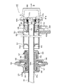
(加熱ローラ付近の構造)
次に図16を用いて定着装置12の加熱ローラ付近の構造について説明する。加熱ローラ14は、例えばアルミニウム等の金属製素管14aと、その素管14aの周面の通紙領域Aw上に設けられた表面層14bから構成されている。この表面層14bは、例えばPFA(テトラフルオロエチレン・パーフルオロアルキルビニールエーテル共重合体)樹脂などの被膜、シリコンゴム層、シリコンゴム層とその上を覆うPFAチューブなどで構成されている。
(Structure around the heating roller)
Next, the structure near the heating roller of the fixing
加熱ローラ14の両端開口部付近の内側には、例えばアルミニウム等からなる略円盤状の放熱防止部材(以下、アブソーバという)14c,14dが固定されている。このアブソーバ14c,14dは、加熱ローラ14の内側に挿入された複数本のヒータランプ25からの輻射熱が加熱ローラ14の外側に放出して、機内が高温になるのを防止している。
Inside the vicinity of the opening portions at both ends of the
同図に示すようにアブソーバ14c,14dは、加熱ローラ14の通紙領域Awよりも少し外側に設置されており、従ってアブソーバ14cとアブソーバ14dの間隔は通紙領域Awの軸方向の長さよりも若干長くなっており、更に各ヒータランプ25の長さはアブソーバ14cとアブソーバ14dの間隔よりも若干長くなっている。
As shown in the figure, the
アブソーバ14c,14dの全部あるいはその一部が加熱ローラ14の通紙領域Awよりも内側にあると、ヒータランプ25からの輻射熱の伝達がアブソーバ14c,14dによって邪魔され、そのために加熱ローラ14の表面温度が所望の温度に達しない懸念があるから、アブソーバ14c,14dは加熱ローラ14の通紙領域Aw内に入らないように配置されている。
If all or part of the absorbers 14c and 14d are located inside the sheet passing area Aw of the
加熱ローラ14の両端部は、センタリング部材46,47を有する保持部材48,49を介して定着装置のフレーム50,50に支持されている。
Both ends of the
保持部材48には軸受51を介してセンタリング部材46が設けられ、そのセンタリング部材46が加熱ローラ14の一方の開口端内側に挿入されている。又、軸受51は、それの周方向に設置された複数のスプリング52と、保持部材48の内側端面に取り付けられたストッパー板53により、加熱ローラ14の熱膨張や周囲の支持部材のばらつきを吸収できるようになっている。加熱ローラ14に組み込んだ状態では、スプリング52が若干圧縮されて同図に示すようにセンタリング部材46ならびに軸受51とストッパー板53の間に隙間が形成されている。保持部材48は複数の蝶ネジ54によって一方のフレーム50に固定されている。
The holding
保持部材49には加熱ローラ14を回転する加熱ローラ駆動モータ(図示せず)からの駆動力を受けるギア55が設けられ、保持部材49は軸受56,57を介してハウジング58,59により回転自在に支持されている。
The holding
加熱ローラ14のセンタリング部材47と対向する開口端部には軸方向に沿って延びたキー溝(図示せず)が形成され、一方、センタリング部材47の端部にはキー溝に嵌入するキー(図示せず)が設けられ、加熱ローラ14とセンタリング部材47はこのキー構造を介して連結されている。従って加熱ローラ駆動モータの駆動力は、ギア55、保持部材49、センタリング部材47ならびにキー構造を介して加熱ローラ14に伝達され、加熱ローラ14が所定の方向に回転される。
A key groove (not shown) extending along the axial direction is formed at an opening end portion of the
加熱ローラ14からセンタリング部材46,47への熱の流出や損傷を防ぐために、加熱ローラ14の両端とセンタリング部材46,47との間に耐熱性合成樹脂からなるリング60が介挿されている。なお、センタリング部材47側のリング60には、加熱ローラ14のキー溝と対応する位置に溝状の切欠部(図示せず)が形成され、キーとキー溝の嵌合を許容している。
In order to prevent the outflow and damage of heat from the
加熱ローラ14の熱源となる複数本のヒータランプ25は、各ヒータランプ25の両端を保持するランプホルダ61、62により束ねられてランプカートリッジ63を構成しており、このランプカートリッジ63は図に示すように加熱ローラ14の内側中央部に設置される。
A plurality of
(ランプカートリッジの着脱)
次に図17を用いてランプカートリッジ63の着脱について説明する。
ランプカートリッジ63の交換あるいは後述する加熱ローラ14の交換時には、同図に示されているように紙筒あるいは耐熱性樹脂で成形された筒体などからなる保護筒体64が用いられる。保護筒体64の外径は保持部材48の内径ならびにハウジング59の内筒部59bの内径と略同寸、保護筒体64の内径はランプホルダ62の外径と略同寸、保護筒体64の長さは左右のフレーム50,50の間隔よりも若干長く設計されている。
(Removing the lamp cartridge)
Next, the attachment / detachment of the
When the
ランプカートリッジ63を加熱ローラ14内に挿入する際には、まず、ランプカートリッジ63をランプホルダ62側から保護筒体64内に挿入し、保護筒体64の右端部を他方のランプホルダ61の端面に当接する(図17参照)。ランプホルダ62の先端部は、保護筒体64への挿入を容易にするため傾斜部62aが設けられている。
When inserting the
このようにして保護筒体64で覆ったランプカートリッジ63を図17の矢印Aに示すように保持部材48側(プリンタの前面側)から挿入し、保護筒体64は保持部材48,アブソーバ14c,アブソーバ14dならびにハウジング59の内筒部59bの内側を通る。
The
図18は、アブソーバ14dの断面図である。アブソーバ14dの全体の形状は略円盤状をしており、中央部に加熱ローラ14の軸方向に沿って延びた円筒状の摺動部85が設けられ、その摺動部85とアブソーバ14dの外周部86との間は、図17に示すように外周部86側よりも摺動部85側の方が加熱ローラ14の開口部に近くなるように開口側に向けて若干傾斜した傾斜部87で連結されている。摺動部85の内側には挿通穴88が形成され、この挿通穴88の内径は保護筒体64の外径と略同寸に設計されている。本実施例の場合、摺動部85の軸方向の長さは5〜10mmになっている。
FIG. 18 is a cross-sectional view of the
前述のように保持部材48の中空部,アブソーバ14dの挿通穴88ならびにハウジング59の内筒部59bの内径は保護筒体64の外径と略同寸に設計され、さらにアブソーバ14dには挿通穴88側に向けて傾斜した傾斜部87が設けられているから、保護筒体64(ランプカートリッジ63)は挿入方向がぶれることなく、スムーズに加熱ローラ14内に挿入される。
As described above, the hollow portion of the holding
そしてランプホルダ61の外周部が保持部材48に当接した所でランプカートリッジ63の挿入が停止する。このとき保護筒体64の挿入方向先端部はハウジング59から機外に突出しているため、その突出部分を持って保護筒体64を矢印A方向に加熱ローラ14から引き抜くことにより、ランプカートリッジ63の装着が終了する。
Then, the insertion of the
ランプカートリッジ63を加熱ローラ14から取り出す際には、保護筒体64を同図の矢印Bに示すようにプリンタの後面側から、ハウジング59の貫通孔59aに挿入し、ハウジング59の内筒部59b、ランプホルダ62の傾斜部62a、アブソーバ14dの摺動部85(挿通穴88)ならびに保持部材48に案内されて、保護筒体64の挿入方向先端部をランプホルダ61の端面に当接する。これによりランプホルダ62が保護筒体64内に収納され、さらに保護筒体64を挿入することにより、ランプカートリッジ63が保護筒体64と共に矢印B方向に押し出されて、ランプカートリッジ63の取り出しができる。
When taking out the
このようにランプカートリッジ63を保護筒体64で覆って挿入あるいは取り出しを行うことにより、ランプカートリッジ取扱中のヒータランプ25の損傷を防止することができる。紙筒は断熱性があり、所定の機械的強度を有し、安価で入手し易いため保護筒体64として好適である。
Thus, the
アブソーバ14dに設けられた傾斜部87は保護筒体64を矢印A方向に挿入する際の案内に役立つ他、加熱ローラ14の表面温度差を低減するのにも役立つ。すなわち、加熱ローラ14における通紙領域Aw(図16参照)の端部側の表面温度は通紙領域Awの中央部側の表面温度よりも下がり気味であり、端部側と中央部側とでは温度差が発生し易い。
The
そこで図16に示すように、アブソーバ14dを加熱ローラ14の通紙領域Awのすぐ外側に配置し、そのアブソーバ14dに加熱ローラ14の開口部側(ヒータランプ25の端部側)に向けて延びた傾斜部87を設ければ、その傾斜部87によってヒータランプ25の端部側で発生した熱を集めて、加熱ローラ14の通紙領域Aw端部側の表面温度を高め、前述の表面温度差を低減する効果がある。
なお、本実施例ではアブソーバ14dに傾斜部87を設けたが、他方のアブソーバ14cに傾斜部を設けることも可能である。
Therefore, as shown in FIG. 16, the
In the present embodiment, the
(加熱ローラの交換補助具の構成)
次に加熱ローラ14の交換補助具について説明する。本実施例に係る交換補助具は、案内シャフト30と支援ユニット40と支承ローラ部材70から構成されている。
(Configuration of heating roller replacement aid)
Next, a replacement aid for the
案内シャフト30はアルミニウム(金属製)などの剛性のある直管体からなり、案内シャフト30の長さは図1に示すように左右のフレーム50,50の間隔よりも若干長く、案内シャフト30の外径は保持部材48の内径、一方のアブソーバ14dにおける摺動部85(図18参照)の内径、ならびにハウジング59の内筒部59bの内径と略同寸に設計されている。案内シャフト30の挿入方向後端部側には、周方向に沿って係合溝30aが形成されている(図2参照)。
The
ハウジング59の側面(プリンタの後面)には、案内シャフト30を固定(ロック)するための板状のストッパー31がピン32によってスライド可能に保持されている。図2は案内シャフト30とストッパー31の係合状態を示す一部拡大断面図、図3はストッパー31の拡大正面図、図4はストッパー31の拡大側面図である。
A plate-
図3ならびに図4に示すように、ストッパー31の上端部には水平方向に折り曲がった摘み部31aが設けられ、ストッパー31の下端部には略半円弧状に延びた係合片31bが形成され、摘み部31aと係合片31bの間には上下方向に延びたスライド溝31cが設けられている。
As shown in FIGS. 3 and 4, the upper end portion of the
摘み部31aはストッパー31を上下する際に使用され、係合片31bはそれを案内シャフト30の係合溝30aに嵌入することにより案内シャフト30の固定(ロック)がなされ、また、スライド溝31cにはピン32が挿通される。略半円弧状に延びた係合片31bの内径は、案内シャフト30における係合溝30aの底面の内径と略同寸に設計されている。
The
本実施例のように、案内シャフト30に周方向に沿って延びた係合溝30aを形成し、一方、ストッパー31に略半円弧状に延びた係合片31bを設ければ、ストッパー31に対する案内シャフト30の挿入方向が規制されることなく、自由に案内シャフト30を挿入することができるとともに、係合片31bの内周部で案内シャフト30を確実に固定(ロック)することができる。
If the engaging
ストッパー31で案内シャフト30を所定の位置に固定(ロック)することにより、後述する加熱ローラ14、保持部材48ならびに支援ユニット40の挿抜動作のときに案内シャフト30が位置ずれすることなく、前述の各部材の挿抜動作をスムーズに行うことができる。
By fixing (locking) the
案内シャフト30の挿入方向先端部の外周には支援ユニット40などの挿入をスムーズにするための傾斜面30bが形成され、案内シャフト30を所定の位置に固定したときに案内シャフト30の挿入方向先端部(傾斜面30b)はフレーム50の側面より若干外側に突出している(図5参照)。
An
支援ユニット40は図6ならびに図7に示すように、ユニット本体45と、ユニット本体45の側面に回動可能に取り付けられた2つのラッチ41と、そのラッチ41の動作をホルダ43に伝えるシャフト42と、一端がシャフト42に連結されて他端が外側に折れ曲がったホルダ43と、部品公差を吸収し加熱ローラ14の固定を確実にさせるためのコイル状のバネ44と、ユニット本体45の側面に取り付けられたハンドル66と、プッシュピン90(図7参照)とから構成されている。
As shown in FIGS. 6 and 7, the
ユニット本体45の中央部に軸方向に沿って貫通した挿通穴45bが設けられ、この挿通穴45の内径は、案内シャフト30の外径と略同寸に設計されている。ユニット本体45の一方の側面には、フランジ部45cが形成されている。
An
前記2つのラッチ41は同形状をしており、一方の端部に形成された半円柱状の回転部41aと、その回転部41aの内側に回転部41aの厚さ方向に対して偏心して設けられた軸部41bと、回転部41aとは反対側に設けられたレバー部41cを有している。この2つのラッチ41は、挿通穴45bを間にして対向するようにユニット本体45に取り付けられている。
The two latches 41 have the same shape, and are provided with a semi-cylindrical
図7に示すようにシャフト42の一端は、ラッチ41の軸部41bに連結されている。さらにホルダ43のシャフト42と連結する側とは反対側の端部には、ユニット本体45の内側側面45aと対向するように屈曲した挟持片部43aが設けられている。
As shown in FIG. 7, one end of the
コイル状のバネ44はユニット本体45に設けられた段状のバネ受け部45eとラッチ41との間に介在され、そのバネ44の内側にシャフト42が挿通して、ラッチ41はバネ44の弾性力により常に外方向に弾性付勢されているが、ラッチ41には側面形状がU字形の抜け止め手段41dが設けられている(図6参照)。
The
プッシュピン90は図7や図8に示すように、加熱ローラ14の端面側と対向する大径部91と、ラッチ41のレバー部41cと対向する小径部92から構成されている。大径部91と小径部92の境界部に段差部93が形成され、小径部92の頭部付近に抜け止めリング94が固定されている。
As shown in FIGS. 7 and 8, the
このプッシュピン90の小径部92は図8に示すように、ユニット本体45に設けられた貫通孔95に挿入され、その貫通孔95の案内により加熱ローラ14の軸方向に移動可能に配置されている。貫通孔95のラッチ41と対向する側には、抜け止めリング94の外径よりも径大の内径を有する凹欠部98が形成されている。
As shown in FIG. 8, the small-
プッシュピン90の段差部93は貫通孔95の一方の開口端と対向し、また抜け止めリング94は凹欠部98の底面と対向しており、支援ユニット40を取り扱うときにプッシュピン90がユニット本体45から不用意に脱落するのを防止(抜止め)している。
The
このプッシュピン90は、図9で点線の小円で示すようにリング60(図示せず)を介して加熱ローラ14の端面と対向する位置で、かつ図7(a)に示すようにラッチ41のレバー部41cと対向する位置に設けられている。
The
図7(b)に示すようにラッチ41のレバー部41cが互いに内側に倒された状態では、プッシュピン90の小径部92がユニット本体45の外側側面45dより若干突出しており、一方、図7(a)に示すようにラッチ41のレバー部41cが互いに外側に倒された状態では、突出とていたプッシュピン90の小径部92がラッチ41のレバー部41cで押されて、プッシュピン90の大径部91がユニット本体45の外周部より突出する長さを有している。
As shown in FIG. 7B, when the
図7(a)は、2つのラッチ41のレバー部41cが互いに外側に向いている状態を示している。このときラッチ41の軸部41bはユニット本体45寄りの位置にあり、従ってホルダ43の挟持片部43aとユニット本体45の内側側面45aの間隔(間隔L)はL1と大きくなっている。この間隔L1は、アブソーバ14cの厚みより若干広く設計されている。またこのとき、プッシュピン90はラッチ41のレバー部41cで押されて、大径部91がユニット本体45の外周部より若干突出している。
FIG. 7A shows a state in which the
この状態から図7(b)に示すように2つのラッチ41のレバー部41cを互いに内側に回転して倒すと、ラッチ41の軸部41bはユニット本体45から離れる方向に移動し、その偏心に伴ってシャフト42ならびにホルダ43も移動して、ホルダ43の挟持片部43aとユニット本体45の内側側面45aの間隔LはL2と狭くなる。この間隔L2は、アブソーバ14cの厚み以下の寸法になっている。またこのとき、ラッチ41のレバー部41cはプッシュピン90から離れており、大径部91はユニット本体45内に収納され、その代わりに小径部92がユニット本体45の外側側面45dから突出している。
When the
前記間隔Lを間隔L2のように狭くすることにより、支援ユニット40がアブソーバ14cに締結され、加熱ローラ14と支援ユニット40が一体化されて、これらを定着装置から抜き差しすることが可能となる。また前記間隔Lを間隔L1のように広くすることにより、支援ユニット40とアブソーバ14cの締結が解除されるとともに、プッシュピン90の大径部91がユニット本体45の外周部から矢印方向に突出し、リング60を介して加熱ローラ14の端面を押すことになり、支援ユニット40が加熱ローラ14から自動的に分離する。
By narrowing the interval L as the interval L2, the
図9は、図10の矢印X−X方向から視たアブソーバ14cとホルダ43の挟持片部43aとの関係を示す図で、同図(a)は支援ユニット40を加熱ローラ14内に挿入したときの状態を示す図、同図(b)は支援ユニット40をアブソーバ14cに取り付ける直前の状態を示す図である。
FIG. 9 is a view showing the relationship between the absorber 14c and the holding
図9(a)に示すようにアブソーバ14cの内周部には、ホルダ43の挟持片部43aが挿通する大きさの切欠部67が2つ対向するように形成されている。支援ユニット40を加熱ローラ14内に挿入すると、ホルダ43の挟持片部43aは切欠部67を通過し、ユニット本体45のフランジ部45cがフレーム50の外側面に当接したときにアブソーバ14cへの挿入も完了する。
As shown in FIG. 9A, two
また図9(a)に示すように、切欠部67の中心部側で、かつ、支援ユニット40の回転方向(矢印方向)には、切欠部67と連通した回転許容部96が形成され、その回転許容部96の奥部が停止端面97となっている。
Further, as shown in FIG. 9A, a
図9(a)の状態でハンドル66を持って支援ユニット40を矢印方向に回転することで、挟持片部43aの付根部43b(図10参照)が回転許容部96に入り込み、付根部43bの先端部が停止端面97に突き当たったところで支援ユニット40の回転が停止される。図9(b)は付根部43bの先端部が停止端面97に突き当たる直前の状態を示しているが、付根部43bの先端部が停止端面97に突き当たった状態ではホルダ43の挟持片部43aは切欠部67から外れてアブソーバ14cの他の内周部と対向する。
When the
図9(a)の状態から支援ユニット40を矢印方向に約30〜60゜(本実施例では30°)回転することにより、支援ユニット40が自動的に止まる位置に停止端面97が設けられている。
When the
このようにして支援ユニット40が自動的に停止した状態で、図10に示すように2つのラッチ41のレバー部41cを互いに内側に回転することにより、シャフト42を介してホルダ43の挟持片部43aがユニット本体45側に引き寄せられて、アブソーバ14cの内周部がホルダ43の挟持片部43aとユニット本体45の内側側面45aの間で挟持される。このようにしてアブソーバ14cを介して支援ユニット40が加熱ローラ14に取り付けられる。
In the state where the
支承ローラ部材70は図11に示すように、支承ローラ71と、その支承ローラ71を回転自在に支持する第1シャフト72と、その第1シャフト72を一方の自由端部に固定するローラプレート73と、そのローラプレート73の基端部側に設けられた第2シャフト74と、その第2シャフト74を回転自在に支持するホルダープレート75から主に構成されている。
As shown in FIG. 11, the supporting
後述するように加熱ローラ14の交換時に、支承ローラ71上を約200℃程度の高温状態の加熱ローラ14が通過するため、支承ローラ71は耐熱性に優れ、加熱ローラ14の表面層14b(図16参照)にダメージを与えないように、表面層14bと同一あるいは同一系統の材料で構成されている。本実施例の場合、加熱ローラ14の表面層14bはPTFE(ポリテトラフルオロエチレン)樹脂、PFA(テトラフルオロエチレン・パーフルオロアルキルビニールエーテル共重合体)樹脂、FEP(テトラフルオロエチレン・ヘキサフルオロプロピレン共重合体)樹脂などのフッ素系樹脂で形成され、支承ローラ71もこれらと同一あるいは同一系統(本実施例の場合はフッ素系樹脂)の材料で構成されている。
As will be described later, since the
また、回転する支承ローラ71上を加熱ローラ14が通過する際、支承ローラ71により加熱ローラ14の表面を傷つけないように、加熱ローラ14の表面と支承ローラ71の表面が点接触するように支承ローラ71の形状は太鼓状に成形されている。
Further, when the
ローラプレート73の一方の側端には、折り曲げによってフック76が一体に設けられ、ホルダープレート75にはフック76が嵌入(係合)する溝部77(図11(e)参照)が形成されている。溝部77の幅寸法は、フック76の板厚と略同寸に設定されている。またホルダープレート75には溝部77と平行に延びて前記第2シャフト74が挿通する長穴78が形成され、後述するようにローラプレート73は上下動可能に支持されている。
A
図11の(a),(b)は、プリンタから加熱ローラ14を引き出すとき或いは挿入するときの支承ローラ部材70の状態を示す図で、(a)は側面図、(b)平面図である。図11(a)に示すようにローラプレート73に設けられているフック76がホルダープレート75に設けられている溝部77に挿入されて(ロック状態)、ローラプレート73の起立状態が維持され、従って支承ローラ71は図15に示すようにフレーム50の交換用開口部82に臨んでいる。
11A and 11B are views showing the state of the
図11の(c),(d)は、支承ローラ部材70を前述の作動位置から後述の待機位置に移す途中の状態を示す図で、(c)は側面図、(d)平面図である。図11(c)に示すようにローラプレート73を矢印E方向に持ち上げて、フック76を溝部77から外し(ロック解除)、次にローラプレート73を第2シャフト74を中心に矢印F方向に約180°回転する。
FIGS. 11C and 11D are views showing a state in the middle of moving the
図11の(e),(f)は、支承ローラ部材70が待機位置ある状態を示す図で、(e)は側面図、(f)平面図である。この状態ではローラプレート73は第2シャフト74に吊り下げられており、従って支承ローラ71は下位置にあってフレーム50の交換用開口部82から離れた待機位置にある(図1参照)。
(E) and (f) of FIG. 11 are views showing a state in which the
図12は、支援ユニット40に対する支承ローラ部材70の配置を示す図である。本実施例の場合、2つの支承ローラ部材70a,70bが用いられ、フレーム50の交換用開口部82の近傍で、支援ユニット40のハンドル66を手で持って加熱ローラ14を引き抜く動作が円滑に実施できる位置に設置されている。
FIG. 12 is a view showing the arrangement of the
具体的に2つの支承ローラ部材70a,70bの設置位置を、加熱ローラ14の下側で、かつ図12に示すように加熱ローラ14のローラ中心Oを通る垂直線79上を0°とすると、支承ローラ71a,71bのローラ軸と直交する中心線80が垂直線79に対して±30°〜±60°程度、好ましくは±40°〜±50°(本実施例では45°)の範囲で交わる位置(角度θ)に設定し、垂直線79を中心として左右対称の位置に支承ローラ部材70a,70bが配置されている。このようにすることにより、支援ユニット40による加熱ローラ14の引出時に支承ローラ部材70a,70bがその動作を干渉することなく、加熱ローラ14を安定に支え、それを引き出す際の不安定要素を排除することができる。
Specifically, when the installation position of the two
図中の符号81は、支承ローラ部材70a,70bを左右対称の位置に取り付ける取付プレートで、この取付プレート81を介して支承ローラ部材70a,70bがフレーム50の外側に固定される(図1参照)。
本実施例では支承ローラ部材70を加熱ローラ14の下方に2個設置したが、加熱ローラ14の上方にも1〜2個程度の支承ローラ部材70を設置することも可能である。この場合も下方の支承ローラ部材70a,70bと同様に、支援ユニット40による加熱ローラ14の引出時に障害にならない位置に設置する必要がある。なお、加熱ローラ14に対する拘束力が高くならないように、上部に設置する支承ローラ部材70は加熱ローラ14との間に所定量の隙間を設ける必要がある。
In the present embodiment, two
(加熱ローラの交換手順)
次に加熱ローラ14の交換手順について説明する。加熱ローラ14の交換は、それ自体が耐用寿命に達したとき、あるいは前述のようにプリンタで求められる要求に応じるために、その要求に合った加熱ローラ14に変更するときに行われる。
(Replacement procedure of heating roller)
Next, a procedure for replacing the
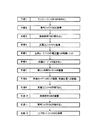
図14は、加熱ローラ14の交換手順を示した工程図である。
同図に示すようにまず手順1で、保護筒体64を用いてランプカートリッジ63を加熱ローラ14の内側から抜き出す。この操作は図17を用いて先に説明した通りであるから、重複する説明は省略する。抜き出したランプカートリッジ63は保護筒体64に収納したままにしておくことにより、剛性のある保護筒体64で保護されているから、交換作業中にランプカートリッジ63が不用意に損傷することはない。
FIG. 14 is a process diagram showing a procedure for replacing the
As shown in the figure, first, in
次に手順2で、案内シャフト30を図1に示すようにハウジング59の貫通孔59aの方(プリンタの後面側)から矢印B方向に挿入する。案内シャフト30はハウジング59の内筒部59b、一方のアブソーバ14dの摺動部85ならびに保持部材48によって案内・保持されて貫通し、所定の位置まで挿入した所でストッパー31が案内シャフト30の係合溝30aに挿入されて(図2参照)、案内シャフト30の装着が完了する。
Next, in
次に手順3で、蝶ネジ54を緩めて、センタリング部材46、軸受51、スプリング52ならびにストッパー板53などを保持した保持部材48を矢印B方向に抜き出す。このとき案内シャフト30の先端部はフレーム50の外側面よりも若干外側に突出しているから、案内シャフト30のガイドによりフレーム50の開口端などに衝突することなく、スムーズに抜き出すことができる。なお、抜き出し途中でセンタリング部材46が加熱ローラ14から離れることにより、スプリング52の復元力によりセンタリング部材46ならびに軸受51がストッパー板53に当接する。
Next, in
このとき図1に示されているように支承ローラ部材70の支承ローラ71は待機位置(下位置)にあるから、保持部材48の抜き出し動作に障害を及ぼすことはない。図5は、加熱ローラ14から保持部材48の抜き出しが終了した状態を示している。
At this time, as shown in FIG. 1, the
次に手順4で、支援ユニット40を傾斜面30bが形成されている案内シャフト30の先端部側からハンドル66を持って挿入する。このとき図7(a)に示すように、ラッチ41のレバー部41は互いに外側に開いた状態になっており、従ってユニット本体45の内側側面45aとホルダ43の挟持片部34aの間隔は広い間隔L1となっている。また、プッシュピン90の大径部91はユニット本体45の外周部から突出している。
Next, in step 4, the
支援ユニット40を加熱ローラ14の開口部に挿入すると、図9(a)に示すようにホルダ43の挟持片43aはアブソーバ14cの切欠部67を通過して、アブソーバ14cの内側に入る。そしてプッシュピン90の大径部91がリング60に当接したところで支援ユニット40の挿入が停止する。
When the
この状態でハンドル66をもって支援ユニット40を図9(a)に示すように矢印方向に回転すると、挟持片43aの根元部43bがアブソーバ14cの停止端面97に当接したところで支援ユニット40の回転が停止する。このように支援ユニット40を回転してもプッシュピン90は、図9(b)に示すように加熱ローラ14の端面と対向した位置にある。
In this state, when the
そして図7(b)ならびに図10に示すように、ラッチ41のレバー部41cを互いに内側に回転することにより、レバー部41cはプッシュピン90から離れ、シャフト42を介してホルダ43の挟持片部34aがユニット本体45側に引き寄せられて、アブソーバ14cの内周部をホルダ43の挟持片部34aとユニット本体45の内側側面45aの間で挟持する。それと同時にプッシュピン90の小径部92が、ユニット本体45の外側側面45bから突出する。このようにして、アブソーバ14cを介して支援ユニット40が加熱ローラ14に取り付けられる。
Then, as shown in FIG. 7B and FIG. 10, by rotating the
次に手順5で、支承ローラ71を作動位置に移動してロックする。この支承ローラ71の移動とロックは、図11(e)に示すローラプレート73を矢印F方向とは反対方向に180°回転させ、フック76を溝部77に嵌入することによってなされる。この移動で図15に示すように、支承ローラ71はフレーム50の交換用開口部82内に臨む。
Next, in
次に手順6で、支援ユニット40のハンドル66をもって高温状態のままの加熱ローラ14をプリンタから抜き出す。このとき案内シャフト30はハウジング59の内筒部59bにより確実に保持されており、アブソーバ14dの摺動部85が案内シャフト30の外周面上を摺動する。そしてフレーム50から外に出た加熱ローラ14の部分は支承ローラ71a,71bによって安定に支承され、加熱ローラ14の引き出しに伴って支承ローラ71a,71bは回転する。図13は、加熱ローラ14の支承状態を示しており、同図に示されているように加熱ローラ14は2つの点接触Pにより支承ローラ71a,71bに支えられている。このようにして約200℃の高温状態にある加熱ローラ14の一部を手で支える必要がなく、加熱ローラ14の抜き出しがスムーズにかつ安全に行われる。
Next, in
加熱ローラ14が抜き出されても、センタリング部材47や保持部材49はそのまま残っている。図15はこの加熱ローラ14の抜き出しの途中の状態を示しており、起立した支承ローラ71は案内シャフト30の先端部よりもフレーム50側に位置しており、加熱ローラ14の抜き出し方向後端部が案内シャフト30の先端部から抜ける前に、加熱ローラ14の外周面が支承ローラ71によって支持されている。
Even if the
次に手順7で、図示していないが交換する新しい加熱ローラ14に支援ユニット40を取り付けて、案内シャフト30を利用して支援ユニット40と共に加熱ローラ14を装着する。この装着時にも支承ローラ71a,71bが使用されるとともに、新しい加熱ローラ14に装着されているアブソーバ14dの摺動部85が案内シャフト30の外周面上を摺動しながら、加熱ローラ14が所定の位置までスムーズに挿入される。
Next, in
次に手順8で、支承ローラ71a,71bをロック解除して、待機位置に移動する。この支承ローラ71a,71bのロック解除と待機位置への移動手順は先に図11を用いて説明したので、重複する説明は省略する。 Next, in step 8, the support rollers 71a and 71b are unlocked and moved to the standby position. Since the procedures for unlocking the support rollers 71a and 71b and moving them to the standby position have been described above with reference to FIG. 11, overlapping description will be omitted.
次に手順9で、支援ユニット40を加熱ローラ14から取り出し、手順10で案内シャフト30を利用して保持部材48を装着して、手順11でストッパー31を外して案内シャフト30を抜き出し、手順12で保護筒体64で覆われたランプカートリッジ63を加熱ローラ14内に挿入し、その後に保持部材48を加熱ローラ14から抜き出してランプカートリッジ63の装着を終了する。
Next, in step 9, the
なお、前記手順7での新しい加熱ローラ14の装着は手順6の加熱ローラ14の抜き出しと逆の操作、前記手順9での支援ユニット40の取り出しは手順4の支援ユニット40の装着と逆の操作である。このときラッチ41のレバー部41cを外側に回転することにより、プッシュピン90の大径部91がユニット本体45の外周部から突出し、リング60を介して加熱ローラ14の端面を押すことになり、それにより支援ユニット40が加熱ローラ14から容易かつ迅速に分離できる。前記手順10での保持部材48の装着は手順3の保持部材48の抜き出しと逆の操作、前記手順11での案内シャフト30の抜き出しは手順2の案内シャフト30の装着と逆の操作、前記手順12でのランプカートリッジ63の装着は手順1のランプカートリッジ63の抜き出しと逆の操作であるので、それらの説明は省略する。
The installation of the
図19は、アブソーバ14dの別の実施例を示す要部拡大断面図である。同図に示すように、アブソーバ14dの摺動部85の少なくとも案内シャフト30や保護筒体64と摺接する内周面に耐熱性樹脂層99が設けられている。この実施例の場合、耐熱性樹脂層99が射出成形体から構成され、その射出成形体がアブソーバ14dの摺動部85に強嵌合されている。また、摺動部85の内周面に耐熱性樹脂をコーティングして耐熱性樹脂層99を形成することも可能である。この実施例の場合、耐熱性樹脂層99の内径が案内シャフト30や保護筒体64の外径と略同寸に設計されている。
FIG. 19 is an enlarged cross-sectional view of a main part showing another embodiment of the
耐熱性樹脂としては、例えばポリイミド樹脂、ポリアミドイミド樹脂、ポリフェニレンオキシド樹脂、ポリスルホン樹脂、フッ素樹脂などが用いられる。このように案内シャフト30や保護筒体64と摺接する部分に耐熱性樹脂層99を設けると、耐熱性樹脂層99の滑性により案内シャフト30や保護筒体64の抜き差しがさらにスムーズになり、また不快な摺動音の発生も無い。
As the heat resistant resin, for example, a polyimide resin, a polyamideimide resin, a polyphenylene oxide resin, a polysulfone resin, a fluorine resin, or the like is used. When the heat-resistant resin layer 99 is provided on the portion that is in sliding contact with the
図20はシャフト摺動部材の別の実施例を示す正面図、図21は図20のY−Y線上の断面図である。前記実施例では放熱防止部材(アブソーバ)を兼ねたシャフト摺動部材について説明したが、本実施例は放熱防止部材(アブソーバ)を兼ねないシャフト摺動部材に係り、例えば熱源を内蔵しない加圧ローラ15(図23参照)に装着される。 20 is a front view showing another embodiment of the shaft sliding member, and FIG. 21 is a cross-sectional view taken along line YY of FIG. In the above-described embodiment, the shaft sliding member that also serves as a heat radiation preventing member (absorber) has been described. However, this embodiment relates to a shaft sliding member that also does not serve as a heat radiation preventing member (absorber), for example, a pressure roller that does not incorporate a heat source. 15 (see FIG. 23).
このシャフト摺動部材200は、加圧ローラ15の内周面に例えば接着剤などによって固定される外周リング部201と、案内シャフト30が挿通する摺動部202と、前記外周リング部201と摺動部202を連結するようにシャフト摺動部材200の径方向に延びた複数本の連結リブ203とから構成されている。連結リブ203と連結リブ203の間は空間部204となっており、シャフト摺動部材200の軽量化と材料使用量の削減を図っている。
The
摺動部202の内径は案内シャフト30の外径と略同寸に設計されている。また、図21に示すように、連結リブ203は外周リング部201から摺動部202に向けて傾斜しており、案内シャフト30の先端部が摺動部202に挿入されるときにガイドの役割を果たしている。このシャフト摺動部材200は、例えばポリイミド樹脂、ポリアミドイミド樹脂、ポリフェニレンオキシド樹脂、ポリスルホン樹脂、フッ素樹脂などの耐熱性樹脂で成形されている。
The inner diameter of the sliding
本実施例ならびに先の実施例では、シャフト摺動部材となるアブソーバ14dならびにシャフト摺動部材200に、円周方向に連続した円筒状の摺動部85,202を設けたが、摺動部は必ずしも円周方向に連続する必要はなく、例えば円周方向に沿って複数本のスリットを設けて案内シャフト30の外周面に対して若干の弾性をもって摺動する摺動部とすることも可能である。
In the present embodiment and the previous embodiment, the cylindrical sliding
図22(a)〜(c)は、支援ユニット40の挟持片部43aでアブソーバ14cの内周部を挟持する際の他の実施例を示す一部側面図である。
アブソーバ14cは加熱ローラ14の内側にあるため、支援ユニット40の挟持片部43aをアブソーバ14cの切欠部67に挿入し、その後支援ユニット40を回転して挟持片部43aが切欠部67から離れてアブソーバ14cの他の内周部と対向しているかを、加熱ローラ14の外側から確認することができない。
22A to 22C are partial side views showing another embodiment when the inner peripheral portion of the
Since the
そのため本実施例では図22に示すように、支援ユニット40におけるユニット本体45の外周面で支援ユニット40の挿入方向先端部側に、1本のユニット側マーク205を印刷などの手段で付ける。一方、加熱ローラ14の外周面の開口部近くに、ローラ側第1マーク206と、ローラ側第2マーク207と、ローラ側第1マーク206からローラ側第2マーク207側に向った矢印マーク208とを印刷などの手段で付ける。ローラ側第1マーク206、ローラ側第2マーク207ならびに矢印マーク208は、加熱ローラ14の外周面でかつ通紙領域a(図16参照)外に設けられる。
Therefore, in this embodiment, as shown in FIG. 22, one unit-
ローラ側第1マーク206は、同図に示すように、支援ユニット40のユニット側マーク205がローラ側第1マーク206と合うように、支援ユニット40を加熱ローラ14の開口部に挿入すれば、図9(a)に示すように支援ユニット40の挟持片部43aがアブソーバ14cの切欠部67に正確に挿入できる位置に設けられている。
If the
ローラ側第2マーク207は、支援ユニット40を矢印マーク208の方向に回転してユニット側マーク205がローラ側第2マーク207と同一線上に来ると、支援ユニット40の挟持片部43aがアブソーバ14cの切欠部67から完全に離れて、切欠部67以外のアブソーバ14cの内周部と対向している位置に設けられている。
When the
図22(a)〜(c)はこれらの一連の動作を示す図で、まず図22(a)の矢印に示すように支援ユニット40を加熱ローラ14の開口部に挿入する際、ユニット側マーク205がローラ側第1マーク206と合うように挿入する。図22(b)に示すようにユニット側マーク205がローラ側第1マーク206と同一線上にあることにより、支援ユニット40の挟持片部43aがアブソーバ14cの切欠部67に正確に挿入できたことを確認することができる。
FIGS. 22A to 22C are diagrams showing a series of these operations. First, when the
なお、ユニット側マーク205の長さは、加熱ローラ14の開口部に支援ユニット40を挿入した状態でも、ユニット側マーク205の一部が加熱ローラ14の開口部から出る長さになっている。
The length of the
次に支援ユニット40を矢印マーク208の方向、すなわち回転許容部96(図9参照)がある方向に回転し、ユニット側マーク205がローラ側第2マーク207と一致した所で支援ユニット40の回転を止める。前記実施例のように回転許容部96の奥部に停止端面96を設けておれば、ユニット側マーク205とローラ側第2マーク207の一致を視覚的に確認できるとともに、挟持片部43aの付根部43bが停止端面96に当接したことを触感的にも確認できる。
Next, the
前記実施例では摺動部材の内径部側に円筒状の摺動部を設けたが、摺動部材を板状の素材で構成し、その摺動部材の中央部に案内シャフトが挿通する挿通穴を形成し、その挿通穴の周辺部を摺動部とする簡単な形状であってもよい。この場合、挿通穴の開口縁のエッジ部を丸く削って、案内シャフトが挿通し易くするとよい。 In the above embodiment, the cylindrical sliding portion is provided on the inner diameter side of the sliding member. However, the sliding member is made of a plate-shaped material, and the insertion hole through which the guide shaft is inserted in the central portion of the sliding member. A simple shape may be used in which the peripheral portion of the insertion hole is a sliding portion. In this case, it is preferable that the edge portion of the opening edge of the insertion hole is rounded to facilitate the insertion of the guide shaft.
前記実施例では加熱ローラ14の交換時にアブソーバ14cを利用して加熱ローラ14と支援ユニット40とを連結したが、加熱ローラ14に支援ユニット40との連結専用係合部(例えば凹部、凸部、穴などの係合部)を設けて、この連結専用係合部を利用して加熱ローラ14と支援ユニット40とを連結することも可能である。
In the above embodiment, the
前記実施例では加熱ローラ14の交換の場合について説明したが、熱源を有するまたは有さない加圧ローラ15の交換にも本発明を適用することは可能である。
In the above-described embodiment, the case of replacing the
前記実施例では加熱ローラ14側に離型剤や潤滑油を塗布したが、加圧ローラ15側、あるいは加熱ローラ14と加圧ローラ15の両側に離型剤や潤滑油を塗布する定着装置(画像形成装置)にも本発明は適用可能である。
In the above-described embodiment, the release agent or lubricant is applied to the
1・・・レーザービームプリンタ、2・・・コロナ帯電器、3・・・回転多面鏡、4・・・光源、5・・・fθレンズ、6・・・現像装置、7・・・用紙、8・・・用紙搬送トラクタ、9・・・用紙搬送トラクタ、10・・・転写器、11・・・用紙ホッパ、12・・・定着装置、13・・・プレヒータ、14・・・加熱ローラ、14a・・・素管、14b・・・表面層、14c・・・放熱防止部材(アブソーバ)、14d・・・放熱防止部材(アブソーバ)、15・・・加圧ローラ、16・・・用紙送出しローラ、17・・・スイングフィン、18・・・パドル、19・・・スタッカテーブル、20・・・清掃装置、21・・・感光ドラム、22・・・コントローラ、23・・・表示画面、24・・・バッファプレート、25・・・ヒータランプ、26・・・ウェブ部材、30・・・案内シャフト、30a・・・係合溝、30b・・・傾斜面、31・・・ストッパー、32・・・ピン、40・・・支援ユニット、41・・・ラッチ、41a・・・回転部、41b・・・軸部、41c・・・レバー部、41d・・・抜け止め手段、42・・・シャフト、43・・・ホルダ、43a・・・挟持片部、43b・・・付根部、44・・・バネ、45・・・ユニット本体、45a・・・内側側面、45b・・・挿通穴、45c・・・フランジ部、45d・・・外側側面、45e・・・バネ受け部、46・・・センタリング部材、47・・・センタリング部材、48・・・保持部材、49・・・保持部材、50・・・フレーム、51・・・軸受、52・・・スプリング、53・・・ストッパー板、54・・・蝶ネジ、55・・・ギア、56・・・軸受、57・・・軸受、58・・・ハウジング、59・・・ハウジング、59a・・・貫通孔、59b・・・内筒部、60・・・リング、61・・・ランプホルダ、62・・・ランプホルダ、62a・・・傾斜部、63・・・ランプカートリッジ、64・・・保護筒体、65・・・リング、66・・・ハンドル、67・・・切欠部、70・・・支承ローラ部材、71・・・支承ローラ、72・・・第1シャフト、73・・・ローラプレート、74・・・第2シャフト、75・・・ホルダープレート、76・・・フック、77・・・溝部、78・・・長穴、79・・・垂直線、80・・・中心線、81・・・取付プレート、82・・・交換用開口部、85・・・摺動部、86・・・外周部、87・・・傾斜部、88・・・挿通穴、90・・・プッシュピン、91・・・大径部、92・・・小径部、93・・・段差部、94・・・抜け止めリング、95・・・貫通孔、96・・・回転許容部、97・・・停止端面、98・・・凹欠部、99・・・耐熱樹脂層、200・・・シャフト摺動部材、201・・・外周リング部、202・・・摺動部、203・・・連結リブ、204・・・空間部、205・・・ユニット側マーク、206・・・ローラ側第1マーク、207・・・ローラ側第2マーク、208・・・矢印マーク、Aw・・・通紙領域。
DESCRIPTION OF
Claims (21)
前記加熱ローラおよび加圧ローラのうちの少なくとも一方のローラが当該ローラの軸方向に沿って前記定着装置から交換可能に支持される定着装置用ローラにおいて、
当該ローラの内側に摺動部材を一体に設け、
その摺動部材は、略円盤状をしており、且つ、当該ローラの交換時に当該ローラ内に挿抜されるローラ挿抜用案内シャフトを挿通する挿通穴を有し、その挿通穴の穴径は前記ローラ挿抜用案内シャフトの外径と略同寸になっていることを特徴とする定着装置用ローラ。 A heating roller and a pressure roller provided so as to be able to press against the heating roller are provided, and a recording medium holding an unfixed toner image on the surface is sandwiched and conveyed between the heating roller and the pressure roller. Used in a fixing device for fixing the toner image on a recording medium by heating and pressurizing while
In the fixing device roller in which at least one of the heating roller and the pressure roller is supported so as to be replaceable from the fixing device along the axial direction of the roller.
A sliding member is integrally provided inside the roller,
The sliding member has a substantially disk shape, and has an insertion hole for inserting a roller insertion / extraction guide shaft that is inserted into and extracted from the roller when the roller is replaced. A roller for a fixing device, characterized in that it is substantially the same size as the outer diameter of the roller insertion / extraction guide shaft .
前記加熱ローラおよび加圧ローラのうちの少なくとも一方のローラが当該ローラの軸方向に沿って交換可能に支持されている定着装置において、
前記交換可能に支持されている定着装置用ローラが請求項1ないし10のいずれか1項に記載の定着装置用ローラであることを特徴とする定着装置。 A heating roller and a pressure roller provided so as to be able to press against the heating roller are provided, and a recording medium holding an unfixed toner image on the surface is sandwiched and conveyed between the heating roller and the pressure roller. Heating and pressurizing while fixing the toner image on the recording medium,
In the fixing device in which at least one of the heating roller and the pressure roller is supported so as to be replaceable along the axial direction of the roller,
The fixing device roller according to claim 1, wherein the fixing device roller supported in a replaceable manner is the fixing device roller according to claim 1.
前記ローラの交換時に前記軸受け保持部材の内側から前記ローラの内側にわたって挿入されて交換するローラの挿抜をガイドするローラ挿抜用案内シャフトを保持する内筒部を、前記軸受け保持部材の内側に設けたことを特徴とする定着装置。 The fixing device according to claim 11, further comprising a bearing that rotatably supports one end of the roller to be replaced, and a bearing holding member that holds the bearing.
An inner cylinder portion that holds a roller insertion / extraction guide shaft that guides insertion / extraction of the roller that is inserted and replaced from the inside of the bearing holding member to the inside of the roller at the time of replacement of the roller is provided inside the bearing holding member. A fixing device.
加熱ローラと、その加熱ローラに対して圧接可能に設けた加圧ローラを有し、前記加熱ローラと加圧ローラの間に前記トナー像を転写した未定着の被記録媒体を通して、トナー像を被記録媒体上に定着する定着装置を備えた画像形成装置において、
前記定着装置が請求項11ないし13のいずれか1項に記載の定着装置であることを特徴とする画像形成装置。 A transfer device for transferring a toner image on an image carrier onto a recording medium;
A heating roller and a pressure roller provided so as to be able to press against the heating roller are provided, and the toner image is covered through an unfixed recording medium on which the toner image is transferred between the heating roller and the pressure roller. In an image forming apparatus provided with a fixing device for fixing on a recording medium,
An image forming apparatus, wherein the fixing device is the fixing device according to claim 11.
前記交換するローラの内側に設けられた摺動部材を貫通するように前記定着装置に着脱可能に取り付けられて、外周面上を前記摺動部材が摺動しながら前記ローラを挿抜するローラ挿抜用案内シャフトと、
前記交換するローラの抜き出し方向の先端部に設けられた支援ユニット連結部材に着脱可能に取り付けられるとともに、前記ローラ挿抜用案内シャフトの端部に外嵌して前記ローラの挿抜を支援する支援ユニットを備えて、
前記支援ユニットを前記支援ユニット連結部材を介して前記交換するローラの先端部に取り付けて、前記支援ユニットごと前記交換するローラを挿抜することで、前記ローラを交換する構成になっていることを特徴とする定着装置のローラ交換補助具。 In a roller replacement auxiliary tool of a fixing device that extracts and replaces at least one of a heating roller and a pressure roller provided so as to be able to come into pressure contact with the heating roller in the axial direction,
For roller insertion / extraction, which is detachably attached to the fixing device so as to pass through a sliding member provided inside the roller to be replaced, and the roller is inserted and removed while the sliding member slides on an outer peripheral surface. A guide shaft;
A support unit that is detachably attached to a support unit connecting member provided at a distal end portion in the extraction direction of the roller to be replaced, and that is externally fitted to an end portion of the roller insertion / extraction guide shaft to support the insertion / extraction of the roller. prepare for,
The support unit is attached to the tip of the roller to be replaced via the support unit connecting member, and the roller is replaced by inserting and removing the roller to be replaced together with the support unit. A roller replacement aid for the fixing device.
前記操作手段と挟持手段により前記支援ユニットを前記支援ユニット連結部材に取り付けられる構成になっていることを特徴とする定着装置のローラ交換補助具。 In the roller replacement aid of the fixing device according to claim 15, wherein the support unit, possess a clamping means for clamping the support unit connecting member of the roller, the operation means for performing the holding operation of the clamping means,
A roller replacement aid for a fixing device, wherein the support unit is attached to the support unit connecting member by the operation means and the clamping means .
前記交換するローラの内側に設けられた摺動部材を貫通するようにローラ挿抜用案内シャフトを挿入して装着する案内シャフト装着工程と、
前記交換するローラの一方の端部を回転自在に支承する軸受けを保持した保持部材を前記ローラ挿抜用案内シャフトに沿って抜き出す保持部材抜き出し工程と、
前記ローラ挿抜用案内シャフトに沿って支援ユニットを挿入して、前記ローラの抜き出し方向先端部に設けられた支援ユニット連結部材に支援ユニットを連結する支援ユニット装着工程と、
前記支援ユニットに連結したローラを、前記摺動部材を介して前記ローラ挿抜用案内シャフトの外周面上を摺動させながら抜き出すローラ抜き出し工程と、
交換する新しいローラの支援ユニット連結部材に支援ユニットを連結して、摺動部材を介して前記ローラ挿抜用案内シャフトの外周面上を摺動させながら支援ユニットとともにローラを装着するローラ装着工程と、
装着したローラから支援ユニットを外して、前記ローラ挿抜用案内シャフトに沿って支援ユニットを取り出す支援ユニット取り出し工程と、
交換した新しいローラの一方の端部を回転自在に支承する軸受けを保持する軸受け保持部材を前記ローラ挿抜用案内シャフトに沿って前記ローラに装着する保持部材装着工程と、
装着していた前記ローラ挿抜用案内シャフトを抜き出す案内シャフト抜き出し工程と
を備えたことを特徴とする定着装置のローラ交換方法。 In the roller replacement method of the fixing device for extracting and replacing at least one of the heating roller and the pressure roller provided so as to be capable of being pressed against the heating roller along the axial direction,
A guide shaft mounting step of inserting and mounting a roller insertion / extraction guide shaft so as to pass through a sliding member provided inside the roller to be replaced; and
A holding member extraction step of extracting a holding member holding a bearing that rotatably supports one end of the roller to be replaced along the guide shaft for roller insertion and extraction;
A support unit mounting step of inserting a support unit along the roller insertion / extraction guide shaft and connecting the support unit to a support unit connecting member provided at a leading end portion in the extraction direction of the roller;
A roller extracting step of extracting the roller connected to the support unit while sliding on the outer peripheral surface of the roller insertion / extraction guide shaft via the sliding member;
A roller mounting step of connecting the support unit to a support unit connecting member of a new roller to be replaced, and mounting the roller together with the support unit while sliding on the outer peripheral surface of the roller insertion / extraction guide shaft via the sliding member;
Removing the support unit from the mounted roller, and taking out the support unit along the roller insertion / extraction guide shaft; and
A holding member mounting step of mounting a bearing holding member that holds a bearing that rotatably supports one end of the replaced new roller along the roller insertion / extraction guide shaft;
A roller replacement method for a fixing device, comprising: a guide shaft extracting step of extracting the roller insertion / extraction guide shaft that has been mounted.
前記ランプカートリッジとローラの間に保護筒体を挿入してランプカートリッジを保護筒体で覆った状態で、保護筒体とともにランプカートリッジをローラから抜き出すランプカートリッジ抜き出し工程を、前記案内シャフト装着工程の前に設け、
前記案内シャフト抜き出し工程後に、保護筒体を挿入したランプカートリッジを新しく装着されたローラの内側に挿入して前記保護筒体をローラから抜き出すランプカートリッジ装着工程を設けたことを特徴とする定着装置のローラ交換方法。 The roller replacement method of the fixing device according to claim 18, wherein the roller to be extracted and the roller to be newly installed have a lamp cartridge inside,
In the state where the protective cylinder is inserted between the lamp cartridge and the roller and the lamp cartridge is covered with the protective cylinder, the lamp cartridge extracting process for extracting the lamp cartridge together with the protective cylinder from the roller is performed before the guide shaft mounting process. Provided in
A fixing device comprising: a lamp cartridge mounting step in which a lamp cartridge into which a protective cylinder is inserted is inserted into a newly mounted roller after the guide shaft is extracted, and the protective cylinder is extracted from the roller. Roller replacement method.
Priority Applications (4)
| Application Number | Priority Date | Filing Date | Title |
|---|---|---|---|
| JP2009199997A JP5402408B2 (en) | 2009-08-31 | 2009-08-31 | Fixing device roller, fixing device, image forming apparatus, fixing device roller replacement aid, and fixing device roller replacement method |
| US12/805,724 US8364062B2 (en) | 2009-08-31 | 2010-08-17 | Fixing roller for fixing unit, fixing unit, image forming apparatus, roller replacement aid for fixing unit, and method of replacing fixing roller in fixing unit |
| EP10251465.0A EP2290468B1 (en) | 2009-08-31 | 2010-08-19 | Fixing roller for fixing unit, fixing unit, image forming apparatus, roller replacement aid for fixing unit, and method of replacing fixing roller in fixing unit |
| CN2010102685984A CN102004428B (en) | 2009-08-31 | 2010-08-30 | Fixing roller, fixing unit, image forming apparatus, roller replacement aid, and method of replacing fixing roller |
Applications Claiming Priority (1)
| Application Number | Priority Date | Filing Date | Title |
|---|---|---|---|
| JP2009199997A JP5402408B2 (en) | 2009-08-31 | 2009-08-31 | Fixing device roller, fixing device, image forming apparatus, fixing device roller replacement aid, and fixing device roller replacement method |
Publications (2)
| Publication Number | Publication Date |
|---|---|
| JP2011053304A JP2011053304A (en) | 2011-03-17 |
| JP5402408B2 true JP5402408B2 (en) | 2014-01-29 |
Family
ID=43062502
Family Applications (1)
| Application Number | Title | Priority Date | Filing Date |
|---|---|---|---|
| JP2009199997A Active JP5402408B2 (en) | 2009-08-31 | 2009-08-31 | Fixing device roller, fixing device, image forming apparatus, fixing device roller replacement aid, and fixing device roller replacement method |
Country Status (4)
| Country | Link |
|---|---|
| US (1) | US8364062B2 (en) |
| EP (1) | EP2290468B1 (en) |
| JP (1) | JP5402408B2 (en) |
| CN (1) | CN102004428B (en) |
Families Citing this family (8)
| Publication number | Priority date | Publication date | Assignee | Title |
|---|---|---|---|---|
| JP5532963B2 (en) * | 2010-01-27 | 2014-06-25 | 株式会社リコー | Fixing apparatus and image forming apparatus having the same |
| JP5423448B2 (en) * | 2010-02-05 | 2014-02-19 | 株式会社リコー | Parts replacement aid for fixing device |
| JP5552943B2 (en) * | 2010-07-29 | 2014-07-16 | 株式会社リコー | Fixing apparatus and image forming apparatus |
| JP6282141B2 (en) * | 2014-03-03 | 2018-02-21 | キヤノン株式会社 | Fixing device |
| CN105235348A (en) * | 2014-07-08 | 2016-01-13 | 中信国安盟固利动力科技有限公司 | Heat-resistant rubber and metal composite heating block, preparation method therefor and application thereof |
| US9498992B2 (en) * | 2014-12-09 | 2016-11-22 | Panasonic Intellectual Property Management Co., Ltd. | Sheet material cooling device and printer including the same |
| CN109624485B (en) * | 2019-01-28 | 2020-08-11 | 汕头市精工东捷制版有限公司 | Printing plate roller of gravure press |
| CN114167704B (en) * | 2021-11-24 | 2023-05-30 | 长城信息股份有限公司 | Laser printer fixing unit heating device |
Family Cites Families (11)
| Publication number | Priority date | Publication date | Assignee | Title |
|---|---|---|---|---|
| JPH05504633A (en) * | 1989-12-13 | 1993-07-15 | オーセ プリンテイング システムズ ゲゼルシャフト ミット ベシュレンクテル ハフツング | Fusing station used in electrophotographic printing or copying equipment |
| DE4209520C1 (en) * | 1992-03-24 | 1993-04-08 | Siemens Nixdorf Informationssysteme Ag, 4790 Paderborn, De | |
| DE10056939C2 (en) | 1999-11-19 | 2003-02-20 | Hitachi Koki Kk | Lamp holder and lamp cartridge using the holder, and fuser using the holder |
| JP3900403B2 (en) * | 2001-03-16 | 2007-04-04 | リコープリンティングシステムズ株式会社 | Fixing device |
| JP2003302801A (en) * | 2002-04-12 | 2003-10-24 | Hitachi Printing Solutions Ltd | Belt carrying device |
| JP2004219491A (en) | 2003-01-09 | 2004-08-05 | Ricoh Co Ltd | Roller used in fixing unit |
| JP4591254B2 (en) | 2005-07-26 | 2010-12-01 | ブラザー工業株式会社 | Image forming apparatus |
| US8135307B2 (en) | 2007-06-22 | 2012-03-13 | Ricoh Company, Ltd. | Transfer belt device, method of assembling the same, and image forming apparatus |
| JP5593656B2 (en) | 2009-01-08 | 2014-09-24 | 株式会社リコー | Fixing device, fixing device roller replacement assisting tool, fixing device roller replacement method, and image forming apparatus |
| JP5428470B2 (en) | 2009-03-31 | 2014-02-26 | 株式会社リコー | Fixing apparatus and image forming apparatus having the same |
| US8249486B2 (en) | 2009-01-08 | 2012-08-21 | Ricoh Company, Ltd. | Fixing unit, roller replacement auxiliary tool of fixing unit, and image forming apparatus |
-
2009
- 2009-08-31 JP JP2009199997A patent/JP5402408B2/en active Active
-
2010
- 2010-08-17 US US12/805,724 patent/US8364062B2/en active Active
- 2010-08-19 EP EP10251465.0A patent/EP2290468B1/en active Active
- 2010-08-30 CN CN2010102685984A patent/CN102004428B/en active Active
Also Published As
| Publication number | Publication date |
|---|---|
| US8364062B2 (en) | 2013-01-29 |
| EP2290468A3 (en) | 2011-11-09 |
| JP2011053304A (en) | 2011-03-17 |
| US20110052258A1 (en) | 2011-03-03 |
| EP2290468B1 (en) | 2018-05-23 |
| CN102004428B (en) | 2012-12-26 |
| EP2290468A2 (en) | 2011-03-02 |
| CN102004428A (en) | 2011-04-06 |
Similar Documents
| Publication | Publication Date | Title |
|---|---|---|
| JP5402408B2 (en) | Fixing device roller, fixing device, image forming apparatus, fixing device roller replacement aid, and fixing device roller replacement method | |
| EP2207065B1 (en) | Fixing unit, roller replacement auxiliary tool of fixing unit, and image forming apparatus | |
| JP4035680B2 (en) | Fixing apparatus and printing apparatus using the same | |
| JP5532963B2 (en) | Fixing apparatus and image forming apparatus having the same | |
| US8774691B2 (en) | Image forming apparatus, fixing device, and fixing method | |
| JP5593656B2 (en) | Fixing device, fixing device roller replacement assisting tool, fixing device roller replacement method, and image forming apparatus | |
| JP5423448B2 (en) | Parts replacement aid for fixing device | |
| JP5428470B2 (en) | Fixing apparatus and image forming apparatus having the same | |
| JP5493921B2 (en) | Roller replacement aid for fixing device | |
| JP5471911B2 (en) | Fixing apparatus and image forming apparatus having the same | |
| JP3900403B2 (en) | Fixing device | |
| JP4062389B2 (en) | Fixing device | |
| JP7152275B2 (en) | Fixing device and image forming device | |
| JP5740918B2 (en) | Fixing apparatus and image forming apparatus | |
| CN103034105B (en) | The fixation unit of fixing ink powder image | |
| JP2012008325A (en) | Fixing device and image forming apparatus having the same | |
| JP2512533B2 (en) | Installation structure of wiping assembly for heat roller | |
| JP2006139035A (en) | Fixing device and image forming apparatus | |
| JPH1026196A (en) | Device for replacing endless belt | |
| JP2003098859A (en) | Thermal fixing device and image forming device | |
| JP2008268534A (en) | Image heating device | |
| JP2010072407A (en) | Fixing device |
Legal Events
| Date | Code | Title | Description |
|---|---|---|---|
| A621 | Written request for application examination |
Free format text: JAPANESE INTERMEDIATE CODE: A621 Effective date: 20120612 |
|
| A977 | Report on retrieval |
Free format text: JAPANESE INTERMEDIATE CODE: A971007 Effective date: 20130529 |
|
| A131 | Notification of reasons for refusal |
Free format text: JAPANESE INTERMEDIATE CODE: A131 Effective date: 20130604 |
|
| A521 | Written amendment |
Free format text: JAPANESE INTERMEDIATE CODE: A523 Effective date: 20130731 |
|
| RD02 | Notification of acceptance of power of attorney |
Free format text: JAPANESE INTERMEDIATE CODE: A7422 Effective date: 20130731 |
|
| TRDD | Decision of grant or rejection written | ||
| A01 | Written decision to grant a patent or to grant a registration (utility model) |
Free format text: JAPANESE INTERMEDIATE CODE: A01 Effective date: 20131001 |
|
| A61 | First payment of annual fees (during grant procedure) |
Free format text: JAPANESE INTERMEDIATE CODE: A61 Effective date: 20131014 |
|
| R151 | Written notification of patent or utility model registration |
Ref document number: 5402408 Country of ref document: JP Free format text: JAPANESE INTERMEDIATE CODE: R151 |