JP5401412B2 - Absolute distance meter with optical switch - Google Patents
Absolute distance meter with optical switch Download PDFInfo
- Publication number
- JP5401412B2 JP5401412B2 JP2010176909A JP2010176909A JP5401412B2 JP 5401412 B2 JP5401412 B2 JP 5401412B2 JP 2010176909 A JP2010176909 A JP 2010176909A JP 2010176909 A JP2010176909 A JP 2010176909A JP 5401412 B2 JP5401412 B2 JP 5401412B2
- Authority
- JP
- Japan
- Prior art keywords
- fiber
- optical
- light beam
- measurement
- switch
- Prior art date
- Legal status (The legal status is an assumption and is not a legal conclusion. Google has not performed a legal analysis and makes no representation as to the accuracy of the status listed.)
- Expired - Fee Related
Links
- 230000003287 optical effect Effects 0.000 title claims description 113
- 239000000835 fiber Substances 0.000 claims description 145
- 239000013307 optical fiber Substances 0.000 claims description 124
- 238000005259 measurement Methods 0.000 claims description 104
- 238000012545 processing Methods 0.000 claims description 62
- 238000000034 method Methods 0.000 claims description 27
- 230000008569 process Effects 0.000 claims description 14
- 230000004044 response Effects 0.000 claims description 13
- 230000001143 conditioned effect Effects 0.000 claims description 8
- 230000010363 phase shift Effects 0.000 claims description 7
- 238000010586 diagram Methods 0.000 description 11
- 230000006870 function Effects 0.000 description 10
- 238000000926 separation method Methods 0.000 description 9
- 239000013078 crystal Substances 0.000 description 6
- 230000007246 mechanism Effects 0.000 description 6
- 230000008901 benefit Effects 0.000 description 5
- 230000000694 effects Effects 0.000 description 5
- 238000005070 sampling Methods 0.000 description 5
- 230000001427 coherent effect Effects 0.000 description 4
- 230000010287 polarization Effects 0.000 description 4
- 238000004364 calculation method Methods 0.000 description 3
- 230000008859 change Effects 0.000 description 3
- 230000008878 coupling Effects 0.000 description 3
- 238000010168 coupling process Methods 0.000 description 3
- 238000005859 coupling reaction Methods 0.000 description 3
- 238000013459 approach Methods 0.000 description 2
- 230000000712 assembly Effects 0.000 description 2
- 238000000429 assembly Methods 0.000 description 2
- 239000002131 composite material Substances 0.000 description 2
- 230000001419 dependent effect Effects 0.000 description 2
- 238000002955 isolation Methods 0.000 description 2
- 238000012986 modification Methods 0.000 description 2
- 230000004048 modification Effects 0.000 description 2
- 230000009467 reduction Effects 0.000 description 2
- 238000002310 reflectometry Methods 0.000 description 2
- 230000001052 transient effect Effects 0.000 description 2
- 238000012152 algorithmic method Methods 0.000 description 1
- 238000004458 analytical method Methods 0.000 description 1
- 238000013480 data collection Methods 0.000 description 1
- 230000001934 delay Effects 0.000 description 1
- 230000000368 destabilizing effect Effects 0.000 description 1
- 239000006185 dispersion Substances 0.000 description 1
- 230000005684 electric field Effects 0.000 description 1
- CPBQJMYROZQQJC-UHFFFAOYSA-N helium neon Chemical compound [He].[Ne] CPBQJMYROZQQJC-UHFFFAOYSA-N 0.000 description 1
- 230000006872 improvement Effects 0.000 description 1
- 238000007726 management method Methods 0.000 description 1
- 238000000691 measurement method Methods 0.000 description 1
- 229910052701 rubidium Inorganic materials 0.000 description 1
- IGLNJRXAVVLDKE-UHFFFAOYSA-N rubidium atom Chemical compound [Rb] IGLNJRXAVVLDKE-UHFFFAOYSA-N 0.000 description 1
- 238000001228 spectrum Methods 0.000 description 1
- 238000004148 unit process Methods 0.000 description 1
Images


Classifications
-
- G—PHYSICS
- G01—MEASURING; TESTING
- G01S—RADIO DIRECTION-FINDING; RADIO NAVIGATION; DETERMINING DISTANCE OR VELOCITY BY USE OF RADIO WAVES; LOCATING OR PRESENCE-DETECTING BY USE OF THE REFLECTION OR RERADIATION OF RADIO WAVES; ANALOGOUS ARRANGEMENTS USING OTHER WAVES
- G01S17/00—Systems using the reflection or reradiation of electromagnetic waves other than radio waves, e.g. lidar systems
- G01S17/02—Systems using the reflection of electromagnetic waves other than radio waves
- G01S17/06—Systems determining position data of a target
- G01S17/42—Simultaneous measurement of distance and other co-ordinates
-
- G—PHYSICS
- G01—MEASURING; TESTING
- G01S—RADIO DIRECTION-FINDING; RADIO NAVIGATION; DETERMINING DISTANCE OR VELOCITY BY USE OF RADIO WAVES; LOCATING OR PRESENCE-DETECTING BY USE OF THE REFLECTION OR RERADIATION OF RADIO WAVES; ANALOGOUS ARRANGEMENTS USING OTHER WAVES
- G01S7/00—Details of systems according to groups G01S13/00, G01S15/00, G01S17/00
- G01S7/48—Details of systems according to groups G01S13/00, G01S15/00, G01S17/00 of systems according to group G01S17/00
- G01S7/497—Means for monitoring or calibrating
-
- G—PHYSICS
- G01—MEASURING; TESTING
- G01S—RADIO DIRECTION-FINDING; RADIO NAVIGATION; DETERMINING DISTANCE OR VELOCITY BY USE OF RADIO WAVES; LOCATING OR PRESENCE-DETECTING BY USE OF THE REFLECTION OR RERADIATION OF RADIO WAVES; ANALOGOUS ARRANGEMENTS USING OTHER WAVES
- G01S17/00—Systems using the reflection or reradiation of electromagnetic waves other than radio waves, e.g. lidar systems
- G01S17/02—Systems using the reflection of electromagnetic waves other than radio waves
- G01S17/06—Systems determining position data of a target
- G01S17/08—Systems determining position data of a target for measuring distance only
-
- G—PHYSICS
- G01—MEASURING; TESTING
- G01S—RADIO DIRECTION-FINDING; RADIO NAVIGATION; DETERMINING DISTANCE OR VELOCITY BY USE OF RADIO WAVES; LOCATING OR PRESENCE-DETECTING BY USE OF THE REFLECTION OR RERADIATION OF RADIO WAVES; ANALOGOUS ARRANGEMENTS USING OTHER WAVES
- G01S7/00—Details of systems according to groups G01S13/00, G01S15/00, G01S17/00
- G01S7/48—Details of systems according to groups G01S13/00, G01S15/00, G01S17/00 of systems according to group G01S17/00
- G01S7/481—Constructional features, e.g. arrangements of optical elements
- G01S7/4818—Constructional features, e.g. arrangements of optical elements using optical fibres
Landscapes
- Engineering & Computer Science (AREA)
- Physics & Mathematics (AREA)
- Computer Networks & Wireless Communication (AREA)
- General Physics & Mathematics (AREA)
- Radar, Positioning & Navigation (AREA)
- Remote Sensing (AREA)
- Electromagnetism (AREA)
- Optical Radar Systems And Details Thereof (AREA)
- Length Measuring Devices By Optical Means (AREA)
- Instruments For Measurement Of Length By Optical Means (AREA)
- Measurement Of Optical Distance (AREA)
Description
本発明は、絶対距離計に関し、より詳細には、絶対距離計内の望ましくないドリフトを低減させ、それによってより正確な距離測定を実現する、光ファイバ交換網を有する絶対距離計に関する。 The present invention relates to absolute rangefinders, and more particularly to absolute rangefinders with fiber optic switching networks that reduce undesirable drift in absolute rangefinders, thereby providing more accurate distance measurements.
関連出願の相互参照
本願は、2009年8月7日出願の「ABSOLUTE DISTANCE METER WITH OPTICAL SWITCH」という名称の米国仮特許出願第61/232,222号の利益を主張する。同願の全体を、本願に引用して援用する。
CROSS REFERENCE TO RELATED APPLICATIONS This application claims the benefit of US Provisional Patent Application No. 61 / 232,222, filed Aug. 7, 2009, entitled “ABSOLUTE DISTANCE METER WITH OPTIC SWITCH”. The entire application is incorporated herein by reference.
一般に、絶対距離計(ADM)は、遠隔ターゲットまでの距離を決定するデバイスである。これは、ターゲットにレーザ光を送り、次いでターゲットが反射または散乱させる光を収集することによって行われる。たとえば金物店で入手可能な消費者製品内で見られるように、ADMを使用して、1次元で距離を測定することができる。ADMは、追加の次元(自由度)に対応する数量を測定する能力を有するより複雑なデバイス内に取り付けることもできる。 In general, an absolute distance meter (ADM) is a device that determines the distance to a remote target. This is done by sending a laser beam to the target and then collecting the light that the target reflects or scatters. For example, ADM can be used to measure distance in one dimension, as found in consumer products available at hardware stores. The ADM can also be mounted in more complex devices that have the ability to measure quantities corresponding to additional dimensions (degrees of freedom).
後者のタイプのデバイスの一例は、3次元の空間座標を測定するレーザ追跡装置である。例示的なシステムは、ブラウンらの米国特許第4,790,651号およびラウらの米国特許第4,714,339号に記載されている。レーザ追跡装置は、当該表面に対して保持され、または固定の入れ子内に配置された再帰反射器ターゲットにレーザビームを送る。最も一般的なタイプの再帰反射器ターゲットは、球面マウント再帰反射器(SMR)である。このSMRは、球内に取り付けられたキューブコーナー再帰反射器を含むことができ、このキューブコーナーの頂点は球の中心に位置する。 An example of the latter type of device is a laser tracker that measures three-dimensional spatial coordinates. Exemplary systems are described in Brown et al. US Pat. No. 4,790,651 and Lau et al. US Pat. No. 4,714,339. The laser tracker sends a laser beam to a retroreflector target that is held against the surface or placed in a fixed nest. The most common type of retroreflector target is a spherical mount retroreflector (SMR). The SMR can include a cube corner retroreflector mounted within the sphere, the vertex of the cube corner being located at the center of the sphere.
レーザ追跡装置に密接に関係するデバイスは、レーザスキャナである。レーザスキャナは、1つ以上のレーザビームを拡散表面上の点へ移動させる。レーザ追跡装置とレーザスキャナはどちらも、座標測定デバイスである。現在の一般的な慣行では、レーザ追跡装置という用語を使用して、距離および角度を測定する能力を有するレーザスキャナデバイスも指す。レーザ追跡装置に密接に関係する別のデバイスは、通常測量士によって使用されるトータルステーションである。レーザスキャナおよびトータルステーションを含むレーザ追跡装置の大まかな定義を、本書全体にわたって使用する。 A device that is closely related to the laser tracking device is a laser scanner. A laser scanner moves one or more laser beams to a point on the diffusing surface. Both the laser tracking device and the laser scanner are coordinate measuring devices. In current common practice, the term laser tracker is also used to refer to a laser scanner device that has the ability to measure distance and angle. Another device closely related to the laser tracker is the total station normally used by surveyors. A general definition of a laser tracking device, including a laser scanner and a total station, is used throughout this document.
レーダデバイスは、電磁波を放出して受け取り、受け取った波を分析してターゲットまでの距離を学習するという点で、レーザ追跡装置に類似している。レーダは通常、電磁スペクトルのRF、マイクロ波、またはミリメートル領域内の波を放出し、一方レーザ追跡装置は通常、可視または近赤外領域内の波を放出する。レーダは、バイスタティックとモノスタティックのいずれであってもよい。モノスタティックレーダは、共通の経路に沿って電磁エネルギーを放出して受け取り、一方バイスタティックレーダは、異なる経路上で放出して受け取る。トータルステーションもまた、バイスタティックとモノスタティックのいずれであってもよい。しかし、高精度の工業計測で使用されるレーザ追跡装置は、モノスタティックである。 Radar devices are similar to laser trackers in that they emit and receive electromagnetic waves and analyze the received waves to learn the distance to the target. Radars typically emit waves in the RF, microwave, or millimeter regions of the electromagnetic spectrum, while laser trackers typically emit waves in the visible or near infrared region. The radar may be either bistatic or monostatic. Monostatic radars emit and receive electromagnetic energy along a common path, while bistatic radars emit and receive on different paths. The total station may be either bistatic or monostatic. However, laser tracking devices used in high-precision industrial measurements are monostatic.
レーザ追跡装置がなぜモノスタティックであるかを理解するために、レーザ追跡装置によって放出され、再帰反射器ターゲットへ進んで再びレーザ追跡装置自体へ再帰反射されるビームについて考慮されたい。追跡装置内でバイスタティックモードが使用された場合、入射レーザビームは再帰反射器の中心から外れるはずであり、反射されたレーザビームは入射ビームに対してシフトするはずである。レーザ追跡装置とともに使用されることが多いこの種の小型の再帰反射器ターゲットは、そのようなバイスタティックデバイスに適合しないはずである。たとえば、一般的なタイプの再帰反射器ターゲットは、直径0.5インチのSMRである。そのようなSMR内のキューブコーナー再帰反射器の開放口直径は通常、約0.3インチであり、これは約7.5mmに等しい。追跡装置からのレーザビームの1/e2照射直径は、ほぼこの大きさ、またはそれより大きいであろう。したがって、レーザビーム内の何らかのシフトにより、ビームはSMRによってクリッピングされるはずである。この結果、追跡装置へ戻る光パワーは、許容できないほど大きく低下するはずである。 To understand why the laser tracker is monostatic, consider the beam emitted by the laser tracker, going to the retroreflector target and retroreflecting back to the laser tracker itself. If a bistatic mode is used in the tracker, the incident laser beam should be off center of the retroreflector and the reflected laser beam should shift with respect to the incident beam. This type of small retroreflector target, often used with laser trackers, should not be compatible with such bistatic devices. For example, a common type of retroreflector target is a 0.5 inch diameter SMR. The open mouth diameter of cube corner retroreflectors in such SMRs is typically about 0.3 inches, which is equal to about 7.5 mm. The 1 / e 2 irradiation diameter of the laser beam from the tracking device will be approximately this size or larger. Thus, any shift in the laser beam should cause the beam to be clipped by the SMR. As a result, the optical power returning to the tracking device should drop unacceptably.
バイスタティックの幾何形状はまた、光ファイバベースのADMシステムにとっても問題となるはずである。光ファイバからレーザ光を放つモノスタティックのレーザ追跡装置では、レーザコリメータは、光ファイバの端面を視準レンズの焦点に配置することによって作製することができる。離れた再帰反射器からの復路では、戻ってくるレーザビームは一般に、出ていくレーザ光に対して中心から外れているが、視準したレーザ光は再び視準レンズに当たる。このファイバ端面は、視準レンズの焦点に配置される。これには、ビームがどこでレンズに当たるかにかかわらず、再帰反射器ターゲットからの光を再びファイバ内に効率的に結合させる効果がある。バイスタティックデバイスでは、光ファイバを受け入れる光学系の整合ははるかに困難であり、結合効率ははるかに低い。 Bistatic geometry should also be a problem for fiber optic based ADM systems. In a monostatic laser tracking device that emits laser light from an optical fiber, the laser collimator can be made by placing the end face of the optical fiber at the focus of the collimating lens. On the return path from a distant retroreflector, the returning laser beam is generally off-center with respect to the outgoing laser light, but the collimated laser light strikes the collimating lens again. This fiber end face is arranged at the focal point of the collimating lens. This has the effect of efficiently coupling the light from the retroreflector target back into the fiber regardless of where the beam hits the lens. In a bistatic device, alignment of the optical system that accepts the optical fiber is much more difficult and the coupling efficiency is much lower.
1つのタイプレーザ追跡装置は干渉計(IFM)だけを含み、絶対距離計をもたない。これらの追跡装置のうちの1つからのレーザビームの経路をある物体が阻止した場合、IFMはその距離基準を失う。このとき操作者は、既知の位置まで再帰反射器を追跡して基準距離にリセットしてからでなければ、測定を継続することができない。この制限を回避する方法は、追跡装置内にADMを置くことである。ADMは、以下により詳細に説明するポイントアンドシュート(point−and−shoot)の形で、距離を測定することができる。レーザ追跡装置の中には、ADMだけを含み、干渉計をもたないものがある。このタイプの例示的なレーザ追跡装置は、ペインらの米国特許第5,455,670号に記載されている。他のレーザ追跡装置は通常、ADMと干渉計の両方を含む。このタイプの例示的なレーザ追跡装置は、マイヤーらの米国特許第5,764,360号に記載されている。 One type of laser tracker includes only an interferometer (IFM) and no absolute rangefinder. If an object blocks the path of the laser beam from one of these trackers, the IFM loses its distance reference. At this time, the operator cannot continue the measurement until the retroreflector is traced to a known position and reset to the reference distance. A way to circumvent this limitation is to place an ADM in the tracking device. The ADM can measure distance in the form of point-and-shoot, described in more detail below. Some laser tracking devices include only ADMs and no interferometers. An exemplary laser tracking device of this type is described in US Pat. No. 5,455,670 to Payne et al. Other laser tracking devices typically include both an ADM and an interferometer. An exemplary laser tracking device of this type is described in US Pat. No. 5,764,360 to Meyer et al.
レーザ追跡装置内のジンバル機構を使用して、追跡装置からのレーザビームをSMRへ誘導することができる。SMRによって再帰反射された光の一部は、レーザ追跡装置に入って位置検出器上へ進む。レーザ追跡装置内の制御システムは、位置検出器上の光の位置を使用して、レーザビームをSMR上の中心に位置決めした状態に保つように、レーザ追跡装置の機械的方位軸および天頂軸の回転角度を調整することができる。このようにして、追跡装置は、当該物体の表面上で動くSMRを追従(追跡)することが可能である。 A gimbal mechanism in the laser tracker can be used to direct the laser beam from the tracker to the SMR. Part of the light retroreflected by the SMR enters the laser tracking device and travels onto the position detector. The control system in the laser tracking device uses the position of the light on the position detector to keep the laser beam centered on the SMR so that the mechanical azimuth and zenith axes of the laser tracking device are The rotation angle can be adjusted. In this way, the tracking device can follow (track) the SMR moving on the surface of the object.
追跡装置の機械的方位軸および天頂軸に取り付けられた角度エンコーダは、(追跡装置の基準枠に対する)レーザビームの方位角度および天頂角度を測定することができる。レーザ追跡装置によって実行される1つの距離測定および2つの角度測定は、SMRの3次元の位置を完全に指定するのに十分である。 Angle encoders attached to the mechanical azimuth and zenith axes of the tracker can measure the azimuth and zenith angles of the laser beam (relative to the reference frame of the tracker). One distance measurement and two angle measurements performed by the laser tracker are sufficient to fully specify the three-dimensional position of the SMR.
レーザ追跡装置に対する主要な適用分野の1つは、物体の表面フィーチャを走査して、それらの幾何特性を決定することである。たとえば、操作者は、それぞれの表面を走査し、次いでそれぞれに幾何平面を適合させることによって、2つの表面間の角度を決定することができる。別の例として、操作者は、球の表面を走査することによって、球の中心および半径を決定することができる。 One of the main areas of application for laser trackers is to scan surface features of objects to determine their geometric properties. For example, an operator can determine the angle between two surfaces by scanning each surface and then fitting each with a geometric plane. As another example, the operator can determine the center and radius of the sphere by scanning the surface of the sphere.
ブリッジスらの米国特許第7,352,446号以前は、レーザ追跡装置で動いているターゲットを走査するには、ADMではなく干渉計が必要とされた。それまで、絶対距離計は、動いているターゲットの位置を正確に見出すには遅すぎた。走査とポイントアンドシュートの両方の能力で完全な機能性を得るには、初期のレーザ追跡装置は、干渉計とADMの両方を必要とした。 Prior to U.S. Pat. No. 7,352,446 to Bridges et al., An interferometer, rather than an ADM, was required to scan a moving target with a laser tracker. Until then, absolute rangefinders were too slow to accurately locate the moving target. To obtain full functionality with both scanning and point-and-shoot capabilities, early laser trackers required both an interferometer and an ADM.
干渉計による距離測定と絶対距離測定の概略的な比較は以下のとおりである。レーザ追跡装置では、干渉計(存在する場合)は、再帰反射器ターゲットが2つの点間を動くときに通過する既知の長さ(通常、レーザ光の2分の1の波長)のインクリメントの数を計数することによって、開始点から終了点までの距離を決定することができる。測定中にビームが切断された場合、カウント数を正確に知ることができなくなり、距離情報は失われる。比較すると、レーザ追跡装置内のADMは、ビームの切断に関係なく再帰反射器ターゲットまでの絶対距離を決定し、また、複数のターゲット間の切換えも可能にする。このため、ADMには「ポイントアンドシュート」測定の能力があると言われている。 A rough comparison of distance measurement with an interferometer and absolute distance measurement is as follows. In a laser tracker, the interferometer (if present) is the number of increments of a known length (usually one-half wavelength of the laser light) that the retroreflector target passes when moving between the two points. Is counted, the distance from the start point to the end point can be determined. If the beam is cut during the measurement, the count number cannot be known accurately and the distance information is lost. In comparison, the ADM in the laser tracker determines the absolute distance to the retroreflector target regardless of beam cutting and also allows switching between multiple targets. For this reason, ADM is said to have the ability to measure “point and shoot”.
干渉計測定にはいくつかの誤差要因が存在するが、大部分の場合、主な誤差は、空気中のその経路上のレーザ光の平均波長の値にある。空間内のある点の波長は、レーザ光の真空波長をその点の空気の屈折率で割った値に等しい。レーザの真空波長は通常、高い精度(10,000,000分の1より良好)で知られているが、空気の平均屈折率は、それほど正確には知られていない。空気の屈折率は、まずセンサを使用して空気の温度、圧力、および湿度を測定すること、次いでこれらの測定値を、シダー(Ciddor)の等式またはエドリン(Edlin)の等式などの適切な等式に挿入することによって見出される。 There are several error factors in interferometer measurements, but in most cases the main error is the value of the average wavelength of the laser light on that path in air. The wavelength at a certain point in space is equal to the vacuum wavelength of the laser light divided by the refractive index of the air at that point. The vacuum wavelength of the laser is usually known with high accuracy (better than 1 in 10,000,000), but the average refractive index of air is not known so accurately. The refractive index of air is determined by first measuring the temperature, pressure, and humidity of the air using a sensor, and then measuring these measurements as appropriate, such as the Ciddor equation or the Edlin equation. It is found by inserting into the equation.
しかし、温度、圧力、および湿度は空間全体にわたって均一ではなく、センサも完全に正確ではない。たとえば、摂氏1度の平均温度の誤差は、約百万分の1(ppm)の屈折率の誤差をもたらす。上記のように、空気中の光の波長は、空気の屈折率に反比例する。 However, temperature, pressure, and humidity are not uniform throughout the space, and the sensors are not perfectly accurate. For example, an average temperature error of 1 degree Celsius results in an error in refractive index of about 1 part per million (ppm). As described above, the wavelength of light in the air is inversely proportional to the refractive index of air.
同様に、ADMでは、振幅変調包絡線(曖昧性範囲とも呼ばれる)のいわゆるADM波長は、空気の群屈折率に反比例する。この類似性のため、温度、圧力、および湿度の測定の誤差は、ADMシステムと干渉計システムに対してほぼ等しい計算距離の誤差をもたらす。 Similarly, in ADM, the so-called ADM wavelength of the amplitude modulation envelope (also called ambiguity range) is inversely proportional to the group index of air. Due to this similarity, temperature, pressure, and humidity measurement errors result in approximately equal computational distance errors for the ADM and interferometer systems.
しかし、ADMは、干渉計では見られない誤差を受けやすい。距離を測定するために、干渉計は電気カウンタを使用して、2つの光ビームの位相が合いまた位相がずれた回数を追跡する。このカウンタは、わずかなアナログの差に応答する必要のないデジタルデバイスである。比較すると、ADMは通常、位相シフトまたは時間遅延などのアナログ値を高い精度で測定する必要がある。 However, ADMs are subject to errors that are not seen with interferometers. To measure the distance, the interferometer uses an electrical counter to track the number of times the two light beams are in phase and out of phase. This counter is a digital device that does not need to respond to slight analog differences. In comparison, ADMs typically need to measure analog values such as phase shifts or time delays with high accuracy.
大部分の高性能のADMでは、レーザ光は、レーザ光源に電気信号を印加することによって、またはこのレーザ光を、音響光学変調器もしくは電気光学変調器などの外部変調器を通って送ることによって変調される。この変調されたレーザ光は、ADMから遠隔ターゲットへ送られる。遠隔ターゲットは、再帰反射器または拡散表面とすることができる。光は、遠隔ターゲットから反射または散乱して、少なくとも部分的に再びADM内へ入る。 In most high performance ADMs, the laser light is applied by applying an electrical signal to the laser light source or by sending the laser light through an external modulator such as an acousto-optic modulator or an electro-optic modulator. Modulated. This modulated laser light is sent from the ADM to the remote target. The remote target can be a retroreflector or a diffusing surface. The light reflects or scatters from the remote target and at least partially reenters the ADM.
ADMが直面する難点を理解するために、時間的に非干渉性のアーキテクチャおよび時間的に干渉性のアーキテクチャという2つの一般的なADMアーキテクチャについて考慮する。いくつかの時間的に干渉性のシステムでは、戻ってくるレーザ光は、別の位置からのレーザ光と混合されてから光検出器へ送られ、光検出器は、その光を電気信号に変換する。この信号を復号して、ADMから遠隔ターゲットまでの距離を見出す。そのようなシステムでは、レーザ光の振幅、位相、または波長に変調を加えることができる。他の時間的に干渉性のシステムでは、異なる波長を有するいくつかの純粋なレーザ線が組み合わされてから、再帰反射器へ送られる。これらの異なる光の波長は検出器で組み合わされ、それによって「合成」変調を提供する。 In order to understand the difficulties faced by ADM, consider two common ADM architectures: a temporally incoherent architecture and a temporally incoherent architecture. In some temporally coherent systems, the returning laser light is mixed with the laser light from another location and then sent to the photodetector, which converts the light into an electrical signal To do. This signal is decoded to find the distance from the ADM to the remote target. In such a system, modulation can be applied to the amplitude, phase, or wavelength of the laser light. In other temporally coherent systems, several pure laser lines with different wavelengths are combined before being sent to the retroreflector. These different wavelengths of light are combined at the detector, thereby providing “synthetic” modulation.
時間的に非干渉性の光システムでは、光は通常、光検出器内で別の波長の光と混合されない。最も簡単なタイプの時間的に非干渉性のシステムは単一の測定チャネルを使用し、基準チャネルを使用しない。通常、そのようなシステム内のレーザ光の光パワーは変調される。再帰反射器から戻る光は光検出器に当たり、光検出器はその光を、同じ変調周波数を有する電気信号に変換する。この信号を電気的に処理して、追跡装置からターゲットまでの距離を見出す。このタイプのシステムの主な欠点は、電気および光学構成要素の応答が時間とともに変動することで、演算された距離にジッタおよびドリフトをもたらす恐れがあることである。 In temporally incoherent optical systems, the light is usually not mixed with light of another wavelength within the photodetector. The simplest type of temporally incoherent system uses a single measurement channel and does not use a reference channel. Usually, the optical power of the laser light in such a system is modulated. The light returning from the retroreflector strikes the photodetector, which converts the light into an electrical signal having the same modulation frequency. This signal is electrically processed to find the distance from the tracking device to the target. The main drawback of this type of system is that the response of electrical and optical components can vary over time, which can result in jitter and drift in the computed distance.
時間的に非干渉性のシステム内のこれらの誤差を低減させるために、1つの手法は、測定チャネルに加えて基準チャネルを作製することである。これは、2組の電子機器を作製することによって行われる。1組の電子機器は、測定チャネル内に位置する。離れた再帰反射器から戻された変調させたレーザ光は、光検出器によって電気信号に変換され、この組の電子機器を通過する。他方の組の電子機器は、基準チャネル内に位置する。電気変調信号は、この第2の組の電子機器に直接印加される。測定チャネル内で見出された距離から基準チャネル内で測定された距離を引くことによって、ADMの読取り値のジッタおよびドリフトが低減される。このタイプの手法は、特に温度に応じて、電気構成要素によってもたらされる変動性の大部分を取り除く。しかし、レーザおよび検出器などの電気光学構成要素の違いから生じる変動性を取り除くことはできない。 In order to reduce these errors in a temporally incoherent system, one approach is to create a reference channel in addition to the measurement channel. This is done by making two sets of electronic equipment. A set of electronics is located in the measurement channel. The modulated laser light returned from the remote retroreflector is converted into an electrical signal by a photodetector and passes through this set of electronic devices. The other set of electronics is located in the reference channel. The electrical modulation signal is applied directly to this second set of electronic equipment. By subtracting the distance measured in the reference channel from the distance found in the measurement channel, the jitter and drift of the ADM reading is reduced. This type of approach removes most of the variability caused by the electrical components, especially depending on the temperature. However, variability resulting from differences in electro-optic components such as lasers and detectors cannot be removed.
これらの誤差をさらに低減させるために、変調させたレーザ光の一部を分割して基準チャネル内の光検出器へ送ることができる。測定および基準チャネルの変調させたレーザ光の変動の大部分はコモンモードであり、測定距離から基準距離が引かれるときに取り消される。 In order to further reduce these errors, a portion of the modulated laser light can be split and sent to the photodetector in the reference channel. Most of the modulation of the modulated laser light in the measurement and reference channels is common mode and is canceled when the reference distance is subtracted from the measurement distance.
これらの改善にかかわらず、そのようなADMシステム内のドリフトは、特に長時間にわたって、または大きな温度変化にわたって、やはり比較的大きいことがある。上記で論じたアーキテクチャはすべて、測定および基準チャネル内で同一ではない光学および電気要素の変動によってもたらされるドリフトおよび繰返し性誤差を受けやすい。ADMシステム内で使用される光ファイバは、温度とともに光路長さを変化させる。ADMシステム内で使用される、増幅器およびフィルタなどの電気アセンブリは、温度とともに電気位相を変化させる。 Despite these improvements, drift in such ADM systems can still be relatively large, especially over long periods of time or over large temperature changes. All of the architectures discussed above are subject to drift and repeatability errors caused by optical and electrical element variations that are not identical in the measurement and reference channels. Optical fibers used in ADM systems change the optical path length with temperature. Electrical assemblies such as amplifiers and filters used in ADM systems change the electrical phase with temperature.
レーザ追跡装置内のADMのドリフトの影響を大幅に低減させる方法および装置は、ブリッジスの米国特許第6,847,436号に教示されている。同特許の内容を、本願に引用して援用する。この方法は、チョッパアセンブリを使用して、戻ってくるレーザ光を測定または基準経路へ交互に再誘導することに関する。この方法はよく機能するが、チョッパホイールの最大回転率、したがってADMのデータ収集率には制限がある。 A method and apparatus for significantly reducing the effects of ADM drift in a laser tracker is taught in US Pat. No. 6,847,436 to Bridges. The contents of this patent are incorporated herein by reference. This method involves using a chopper assembly to alternately redirect the returning laser light into the measurement or reference path. While this method works well, there are limitations on the maximum chopper wheel rotation rate, and hence the data collection rate of the ADM.
動いている再帰反射器までの距離を測定する方法は、ブリッジスらの米国特許第7,352,446号に教示されている。同特許の内容を、本願に引用して援用する。米国特許第7,352,446号の方法を使用して可能な限り最高の性能を得るために、これらの距離は、高い率、好ましくは少なくとも10kHzの率で再び演算される。このように高いデータ率で、米国特許第6,847,436号のような機械チョッパを作製するのは困難である。したがって、ADMドリフトの問題を解決するには、別の方法を見出す必要がある。 A method for measuring the distance to a moving retroreflector is taught in US Pat. No. 7,352,446 to Bridges et al. The contents of this patent are incorporated herein by reference. In order to obtain the best possible performance using the method of US Pat. No. 7,352,446, these distances are recalculated at a high rate, preferably at a rate of at least 10 kHz. With such a high data rate, it is difficult to produce a mechanical chopper such as US Pat. No. 6,847,436. Therefore, another method must be found to solve the ADM drift problem.
2つの自由空間光路間で光学系ビームを機械的に切り換えることによって、距離計のドリフトを補正することが可能である。一方の光路は計器の内部にあり、これを基準経路と呼ぶ。第2の光路は計器から測定されている物体へ進み、次いで計器へ戻る。これを測定経路と呼ぶ。測定および基準経路からの光は、単一の光検出器に当たる。機械スイッチの動作のため、2つの基準経路からの光は、単一の光検出器に同時に当たらない。機械スイッチは、ミラー、プリズム、ビームスプリッタ、またはチョッパホイールなどの機械的に作動される光学構成要素とすることができる。アクチュエータは、ソレノイド、モータ、ボイスコイル、手動調整器、または類似のデバイスとすることができる。光検出器と電気回路は、測定および基準経路に対して同じであるため、ほぼすべてのドリフト誤差はコモンモードであり、取り消される。この方法に基づいた発明の例には、ヒューレットらの米国特許第3,619,058号、マディガンらの米国特許第3,728,025号、デウィットの米国特許第3,740,141号、ナカザワらの米国特許第3,779,645号、ハインズらの米国特許第3,813,165号、シップらの米国特許第3,832,056号、ウェントの米国特許第3,900,260号、ヴィックランドの米国特許第3,914,052号、エプステインの米国特許第4,113,381号、カボルスキーの米国特許第4,297,030号、バックらの米国特許第4,453,825号、オオイシらの米国特許第5,002,388号、ペインらの米国特許第5,455,670号、カネコらの米国特許第5,737,068号、クボの米国特許第5,880,822号、ヒルヌマの米国特許第5,886,777号、ダムの米国特許第5,991,011号、シライらの米国特許第6,765,653号、ブリッジスの米国特許第6,847,436号、オオトモらの米国特許第7,095,490号、オオトモらの米国特許第7,196,776号、シュティルレらの米国特許第7,224,444号、シュミットらの米国特許第7,262,863号、アオキらの米国特許第7,336,346号、ナカムラらの米国特許第7,339,655号、リューらの米国特許第7,471,377号、オオトモらの米国特許第7,474,388号、オサダの米国特許第7,492,444号、オイシらの米国特許第7,518,709号、ルオらの米国特許第7,738,083号、およびウォルフらの米国特許出願公開第US2009/0009747号が含まれる。これらの特許はすべて、遅い機械スイッチを使用するので、動いている再帰反射器を正確に測定するADM内で使用するのに十分なほど迅速に切り換えることができない。 It is possible to correct the drift of the distance meter by mechanically switching the optical system beam between two free space optical paths. One optical path is inside the instrument and is called the reference path. The second optical path goes from the instrument to the object being measured and then returns to the instrument. This is called a measurement path. Light from the measurement and reference paths hits a single photodetector. Due to the operation of the mechanical switch, light from the two reference paths does not strike a single photodetector simultaneously. The mechanical switch can be a mechanically actuated optical component such as a mirror, prism, beam splitter, or chopper wheel. The actuator can be a solenoid, motor, voice coil, manual adjuster, or similar device. Since the photodetector and electrical circuit are the same for the measurement and reference paths, almost all drift errors are common mode and are canceled. Examples of inventions based on this method include Hewlett et al. US Pat. No. 3,619,058, Madigan et al. US Pat. No. 3,728,025, Dewitt US Pat. No. 3,740,141, Nakazawa U.S. Pat. No. 3,779,645, Hines et al. U.S. Pat. No. 3,813,165, Ship et al. U.S. Pat. No. 3,832,056, Went U.S. Pat. No. 3,900,260, Vickland U.S. Pat. No. 3,914,052, Epstein U.S. Pat. No. 4,113,381, Kaborsky U.S. Pat. No. 4,297,030, Buck et al. U.S. Pat. No. 4,453,825, US Patent No. 5,002,388 to Oishi et al., US Patent No. 5,455,670 to Paine et al., US Patent No. 5,737,068 to Kaneko et al., US Patent for Kubo US Pat. No. 5,880,822, Hilunuma US Pat. No. 5,886,777, Dam US Pat. No. 5,991,011, Shirai et al. US Pat. No. 6,765,653, Bridges US Pat. US Pat. No. 6,847,436, Otomo et al. US Pat. No. 7,095,490, Otomo et al. US Pat. No. 7,196,776, Stille et al. US Pat. No. 7,224,444, Schmidt et al. US US Pat. No. 7,262,863, Aoki et al. US Pat. No. 7,336,346, Nakamura et al. US Pat. No. 7,339,655, Liu et al. US Pat. No. 7,471,377, Otomo et al. U.S. Patent No. 7,474,388, Osada U.S. Patent No. 7,492,444, Oishi et al. U.S. Patent No. 7,518,709, Luo et al. U.S. Patent No. 7,738,083, And it includes U.S. Patent Application Publication No. US2009 / 0009747 of Wolff et al. All of these patents use slow mechanical switches so that they cannot switch quickly enough to be used in an ADM that accurately measures a moving retroreflector.
別の可能性は、距離計の光学部分ではなく電気部分だけでドリフトを補正することである。この場合、基準光路からの光は基準光検出器へ送られ、測定光路からの光は測定光検出器へ送られる。基準および光検出器からの電気信号は電気スイッチへ進み、電気スイッチは、2つの検出器からの電気信号を単一の電気ユニットへ交互に経路指定する。電気ユニットは、この信号を処理してターゲットまでの距離を見出す。この方法に基づいた発明の例には、ヘルシャーの米国特許第3,365,717号、レイファーの米国特許第5,742,379号、シュタインレヒナーの米国特許第6,369,880号、ギーガーの米国特許第6,463,393号、ギーガーの米国特許第6,727,985号、ギーガーの米国特許第6,859,744号、およびギーガーの米国特許第6,864,966号が含まれる。電気スイッチを使用すると、ADMシステムの電気部分のドリフトを低減させることができるが、光学部分からのドリフトを取り除くことはできない。光学部分からのドリフトは通常、電気部分のドリフトと同じ大きさであり、またはそれより大きい。さらに、数GHzで変調される電気信号内の位相シフトを回避するのに十分なほど迅速に切り換えることができる電気交換システムを実施するのは困難である。有用性が制限され、また実装が困難であるため、電気スイッチは、ADM内のドリフトを補正するのに良好な解決策ではない。 Another possibility is to correct the drift only in the electrical part and not in the optical part of the rangefinder. In this case, light from the reference light path is sent to the reference light detector, and light from the measurement light path is sent to the measurement light detector. The electrical signals from the reference and photodetectors go to an electrical switch, which alternately routes the electrical signals from the two detectors to a single electrical unit. The electrical unit processes this signal to find the distance to the target. Examples of inventions based on this method include Helcher US Pat. No. 3,365,717, Raifer US Pat. No. 5,742,379, Steinlechner US Pat. No. 6,369,880, Giger ’s US Pat. US Pat. No. 6,463,393, Giger US Pat. No. 6,727,985, Giger US Pat. No. 6,859,744, and Giger US Pat. No. 6,864,966. Using an electrical switch can reduce the drift of the electrical part of the ADM system, but cannot remove the drift from the optical part. The drift from the optical part is usually as large or larger than the drift of the electrical part. Furthermore, it is difficult to implement an electrical exchange system that can be switched quickly enough to avoid phase shifts in electrical signals modulated at several GHz. Due to limited usefulness and difficult to implement, electrical switches are not a good solution to compensate for drift in the ADM.
バイスタティック距離計の場合、光ファイバスイッチの使用について論じる2つの参考文献が存在する。コンスタンティクスの米国特許出願公開第US2009/0046271号は、出ていくビーム経路内に1つのファイバスイッチが配置され、戻ってくるビーム経路内に第2のファイバスイッチが配置される方法について教示している。これらの2つの光ファイバスイッチを同時に切り換えて、測定または基準経路からの光が光検出器に到達するのを可能にする。コールの米国特許第4,689,489号は、バイスタティック距離計の戻りポートからの光がスイッチの1つのポート内に入り、出ていくビームからの光がスイッチの第2のポート内に供給される、ファイバスイッチの使用について教示している。これらの参考文献に記載のファイバスイッチのアーキテクチャは、上記に論じた理由で、バイスタティックデバイスのみに当てはまり、レーザ追跡装置とともに使用することはできない。 In the case of bistatic rangefinders, there are two references that discuss the use of fiber optic switches. Constantics US Patent Application Publication No. US2009 / 0046271 teaches how one fiber switch is placed in the outgoing beam path and a second fiber switch is placed in the returning beam path. Yes. These two fiber optic switches are switched simultaneously to allow light from the measurement or reference path to reach the photodetector. Cole, US Pat. No. 4,689,489, light from the return port of the bistatic rangefinder enters one port of the switch and light from the outgoing beam is fed into the second port of the switch Teaches the use of fiber switches. The fiber switch architectures described in these references apply only to bistatic devices for the reasons discussed above and cannot be used with laser trackers.
ドリフトをほとんど発生させることなく、動いているターゲットを正確に測定するADMが必要とされている。このADMはモノスタティックとし、光学構成要素と電気構成要素の両方でドリフトを最小限にしなければならない。 What is needed is an ADM that accurately measures a moving target with little drift. This ADM must be monostatic and minimize drift in both optical and electrical components.
本発明の一態様によれば、ターゲットまでの距離を決定する絶対距離計(ADM)は、放出光ビームを放出する光源を含む。ADMはまた、スイッチ制御信号に応答して少なくとも2つの位置間で切り換わる少なくとも1つの光スイッチを有するファイバ交換網を含み、これらの位置のうちの第1の位置は、放出光ビームがファイバ交換網からターゲットの方へ放出され、測定光ビームとしてファイバ交換網内へ後方反射される測定モードを可能にし、これらの位置のうちの第2の位置は、光ビームがファイバ交換網内の基準光ビームを含む基準モードを可能にする。ADMは、時間的に間隔を空けて多重化した形で測定および基準光ビームを検出し、検出した測定および基準光ビームに対応する電気信号を提供する単一チャネル検出器をさらに含む。また、ADMは、電気信号を処理し、それに応答して調整された電気信号を提供する単一チャネル信号処理装置と、調整された電気信号を処理してターゲットまでの距離を決定するデータ処理装置とを含む。 According to one aspect of the invention, an absolute distance meter (ADM) that determines a distance to a target includes a light source that emits an emitted light beam. The ADM also includes a fiber switched network having at least one optical switch that switches between at least two positions in response to a switch control signal, the first of these positions is where the emitted light beam is fiber switched. Enabling a measurement mode that is emitted from the network towards the target and reflected back into the fiber switched network as a measurement light beam, the second of these positions is where the light beam is the reference light in the fiber switched network Enables a reference mode that includes a beam. The ADM further includes a single channel detector that detects the measurement and reference light beams in a time-spaced multiplexed manner and provides an electrical signal corresponding to the detected measurement and reference light beams. Also, the ADM is a single channel signal processing device that processes an electrical signal and provides a conditioned electrical signal in response, and a data processing device that processes the conditioned electrical signal to determine a distance to a target. Including.
実施形態について、限定的ではなく例示的なものである添付の図面を参照して、例示のみを目的として次に説明する。添付の図面では、同じ要素にはいくつかの図で同じ番号を付ける。 Embodiments will now be described, by way of example only, with reference to the accompanying drawings, which are illustrative rather than limiting. In the accompanying drawings, identical elements are numbered the same in several figures.
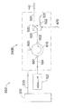
図1に例示的なレーザ追跡装置10を示す。レーザ追跡装置10の例示的なジンバル式ビームステアリング機構12は天頂キャリッジ14を含み、天頂キャリッジ14は、方位基部16に取り付けられ、方位軸20の周りを回転する。天頂キャリッジ14上にペイロード15が取り付けられ、天頂軸18の周りを回転する。追跡装置10の内部で、天頂機械回転軸18と方位機械回転軸20は、ジンバル点22で直交して交差する。ジンバル点22は通常、距離測定に対する原点である。レーザビーム46は、実質上ジンバル点22を通過し、天頂軸18に対して直交に向けられる。言い換えれば、レーザビーム46は、天頂軸18に対して垂直な平面内にある。レーザビーム46は、天頂軸18の周りのペイロード15の回転によって、また方位軸20の周りの天頂キャリッジ14の回転によって、所望の方向に向けられる。追跡装置(図示せず)内部で、天頂機械軸18および方位機械軸20に天頂および方位角度エンコーダが取り付けられ、回転の角度を高い精度で示す。レーザビーム46は、上記の球面マウント再帰反射器(SMR)などの外部再帰反射器26へ進む。ジンバル点22と再帰反射器26の間の径方向の距離、ならびに天頂軸18および方位軸20の周りの回転角度を測定することによって、追跡装置の球面座標系内で、再帰反射器26の位置が見出される。
An exemplary
以下に続く議論で説明するように、レーザビーム46は1つ以上のレーザ波長を含むことができる。見やすくかつ簡単にするために、以下の議論では、ステアリング機構は図1に示す種類のものとする。しかし、他のタイプのステアリング機構も可能である。たとえば、方位および天頂軸の周りを回転するミラーからレーザビームを反射させることが可能であろう。本明細書に記載の技法は、ステアリング機構のタイプにかかわらず適用できる。
As described in the discussion that follows, the
レーザ追跡装置の要素
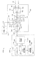
図2Aに、追跡装置の電気光学系アセンブリ250Aを示す。追跡装置の電気光学系アセンブリ250Aは、ADMアセンブリ2000、可視レーザ110、および光学アセンブリ190を含む。ADMアセンブリ2000は、ADM電子機器300、ADMレーザ102、光ファイバ交換網200、およびデータ処理装置400を含む。光学アセンブリ190は、ADMビームコリメータ140、可視ビーム投光器150、追跡アセンブリ170、およびビームエキスパンダ160を含む。
Laser Tracker Elements FIG. 2A shows an electro-
光を変調させるには多くの方法が存在する。1つのタイプの変調は光パワーのものであり、変調信号は通常、正弦波またはパルスである。別のタイプの変調は光波長のものである。このタイプの変調は、干渉性のレーザ距離計で使用されることがある。光源、または電気光学変調器などの外部変調器に直接変調を加えて、レーザ光のパワー、偏光、または位相を変動させることができる。本開示に記載の方法は、これらのタイプの変調のいずれにも適用できる。光は、レーザ、高輝度ダイオード、または任意の他のタイプの光エミッタから生じることができる。以下の文章では、光源をレーザと呼ぶことが多いが、これは、使用できる光源のタイプを限定すると解釈するべきではない。 There are many ways to modulate light. One type of modulation is of optical power and the modulation signal is typically a sine wave or pulse. Another type of modulation is at the optical wavelength. This type of modulation may be used with coherent laser rangefinders. Direct modulation can be applied to a light source or an external modulator such as an electro-optic modulator to vary the power, polarization, or phase of the laser light. The methods described in this disclosure can be applied to any of these types of modulation. The light can come from a laser, a high intensity diode, or any other type of light emitter. In the text below, the light source is often referred to as a laser, but this should not be construed as limiting the type of light source that can be used.
ADMレーザ102からの光は、光ファイバ104内に注入され、ファイバ交換網200へ進む。ファイバ交換網200からの一部の光は、光ファイバケーブル501を通ってADMビームコリメータ140へ進む。ADMビームコリメータ140は、安定フェルール142および正レンズ144を含む。光ファイバは、単一モードタイプのものであることが好ましい。
Light from the
ADMレーザ102が赤外波長で動作する場合、可視レーザビームを提供してビームを見つけやすくすると好都合である。可視レーザ110は、光ファイバケーブル215を通って可視ビーム投光器150へ可視光を送る。可視ビーム投光器150は、安定フェルール152、正レンズ154、およびダイクロイックビームスプリッタ114を含む。ダイクロイックビームスプリッタ114はADMビーム108を透過するが、可視ビーム112を反射する。ビームスプリッタ114の右側では、複合レーザビーム116は、可視レーザビーム112およびADMレーザビーム108を含む。可視レーザビーム112とADMレーザビーム108は、実質上同一直線上にある。レーザビーム116は、ビームスプリッタ118およびビームエキスパンダ160を通過し、より大きな平行レーザビーム46として現れる。ビームエキスパンダ160は、負レンズ162および正レンズ164を含む。
When the
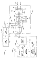
いくつかの適用分野では、ADMに加えて干渉計(IFM)を含むことが望ましい。図2Bに、追跡装置の電気光学系アセンブリ250Bを示す。追跡装置の電気光学系アセンブリ250Bは、可視レーザ110が増分距離計アセンブリ180に置き換えられたことを除いて、電気光学系アセンブリ250Aと同じ要素を含む。増分距離計アセンブリ180は、安定レーザ182および干渉計(IFM)アセンブリ184を含む。安定レーザ182は、赤色ビームを生成する周波数安定化ヘリウム−ネオンレーザであることが好ましい。IFMアセンブリ184は、再帰反射器26までの距離の増分変化を測定する光学系および電子機器(図示せず)を含む。
In some applications, it is desirable to include an interferometer (IFM) in addition to ADM. FIG. 2B shows an electro-
レーザビーム46は、図1に示すように、外部再帰反射器26へ進む。ビーム46は、再帰反射器26から反射し、ビーム48としてレーザ追跡装置10に戻る。レーザビーム46が再帰反射器26の中心に当たった場合、反射されたレーザビーム48は、入射レーザビーム46の経路を戻る。レーザビーム46が再帰反射器26に中心を外れて当たった場合、反射されたレーザビーム48は、入射ビーム46と平行であるが入射ビーム46からずれて戻る。反射されたレーザビーム48は、ビームエキスパンダ160を通って再び追跡装置10に入り、光システムを通って経路を戻る。
追跡アセンブリ170は、ビームスプリッタ118、任意選択の光フィルタ128、および位置検出器130を含む。反射されたレーザビーム48の一部は、ビームスプリッタ118に当たって跳ね返り、任意選択の光フィルタ128を通過して位置検出器130に当たる。光フィルタ128は、再帰反射器26近傍の周囲光など、望ましくない光の波長を阻止する。
The tracking
位置検出器130は、位置検出器130上の光点の位置を示す電気信号を生成する。位置検出器130は、戻ってくる光ビームの位置を示す任意のタイプの検出器とすることができる。たとえば、位置検出器130は、側面効果検出器もしくは象限検出器などの位置敏感型検出器とすることができ、またはCCDもしくはCMOSアレイなどの感光アレイとすることができる。位置検出器の帰線点は、レーザビーム46が再帰反射器26の中心に当たった場合にレーザビーム126が当たる点と定義される。レーザビーム46が再帰反射器26の中心から外れたとき、レーザビーム126は帰線点から外れ、位置検出器130は電気誤差信号を生成する。サーボシステム(図示せず)は、この誤差信号を処理して、レーザビーム46の向きをレーザ追跡装置10から外部再帰反射器26の中心の方へ変えるモータ(図示せず)を活動化させる。こうして、追跡装置10からのレーザビームに、再帰反射器26の動きを追跡させる。
The
ダイクロイックビームスプリッタ114は、戻ってくるADMレーザ光を、ADMビームコリメータ140を通って伝送し、そこでADMレーザ光は、光ファイバ501に結合される。レーザ光は再びファイバ交換網200内へ進み、その一部は、光ファイバ230を通ってADM電子機器300へ進む。ADM電子機器300は、この光信号を電気信号に変換し、レーザ光に加えられる特定のタイプの変調に適した形でこの電気信号を調整する。ADM電子機器300からの信号はデータ処理装置400へ送られ、データ処理装置400は、この信号を処理して結果420を見出す。結果420は、追跡装置のジンバル点22から再帰反射器ターゲット26までの距離である。
追跡装置の電気光学系アセンブリ250A、250Bの構成要素は、完全に追跡装置のペイロード15内に配置しても、部分的に追跡装置のペイロード15内に配置し、また部分的に方位基部16内に配置しても、または完全に方位基部16内に配置してもよい。ADMまたは干渉計の構成要素が方位基部16内に配置される場合、これらは、機械的方位および天頂軸を通ってペイロード15内へ光ファイバケーブルを経路指定することによって、光学構成要素へ接続することができる。この方法は、国際出願第WO2003/062744号に記載されている。同願を、本願に引用して援用する。別法として、ADMまたは干渉計の構成要素が方位基部16内に配置される場合、ADMレーザ102または安定レーザ182によって放出される光は、自由空間を通って、ペイロード内に配置されたビームステアリングミラーへ送ることができる。この方法は、ラウらの米国特許第4,714,339号に記載されている。
The components of the tracker electro-
光ファイバ交換網200は、光信号を光学アセンブリ190へ、および光学アセンブリ190の外へ経路指定して切り換える手段を提供する。ファイバ交換網200について、以下により詳細に説明する。
The fiber
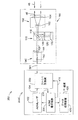
図2Aの可視光レーザ110または図2Bの増分距離計アセンブリ180をなくすことが可能である。この場合、可視ビーム投光器150は不要になる。図3に、その結果得られる電気光学系アセンブリ350を示す。このアーキテクチャは、IFMが必要とされなかった場合、またADMレーザ102が可視レーザ光を放出した場合に適切であろう。このアーキテクチャはまた、IFMが必要とされなかった場合、また可視ポインタビームが必要とされなかった場合に適切であろう。
It is possible to eliminate the
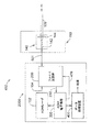
手持ち式距離計または追跡しない他の計器の場合、追跡アセンブリ170、および場合によってはビームエキスパンダ160をなくすことによって、アーキテクチャをさらに簡略化することができる。図4に、その結果得られるADM距離計450を示す。
For handheld rangefinders or other instruments that do not track, the architecture can be further simplified by eliminating the tracking
図2A、2B、3、および4はすべてADMアセンブリ2000を含み、ADMアセンブリ2000は光ファイバ交換網200を含む。ファイバ交換網200の利益は、ADM距離の読取り値のドリフトの低減を可能にすることである。この低減に対する理由は、ADM電子機器300についてより詳細に考慮することによって理解することができる。ADM電子機器に対する特有の実施形態について、図10および11に付随する、すなわちレーザ追跡装置に関連する議論で考慮する。しかし、ADMシステムのドリフトの低減に対するファイバ交換網の利点は、より全体的にADMシステムに当てはまり、たとえばパルス飛行時間ADM、チャープADM、ならびに干渉性および非干渉性のADMを含むことができる。ファイバ交換網200がどのようにしてドリフトの低減を可能にするかについて説明するために、次に図16を参照されたい。図16は、ADM電子機器300の要素についてより概略的に説明する。
2A, 2B, 3, and 4 all include an
図16では、ADM電子機器300は、レーザ送信器310、単一チャネルレーザ受信器320、単一チャネル信号線332、ならびに相互接続線330、334、および336を含む。レーザ送信器310は、様々な信号を生成することができる。相互接続線330からの信号を使用して、ADMレーザ102を変調する。さらに、大部分のタイプのADMシステムは、単一チャネル受信器320内で信号を処理する際に使用される1つ以上の追加の信号を生成する。以下に続く議論で明らかになる理由のため、本明細書ではそのような信号の組合せを単一チャネル信号332と呼ぶ。
In FIG. 16, the
単一チャネル受信器320は、単一検出器322および単一チャネル電子機器324を含む。光は、相互接続線336を介して単一検出器322に到達する。相互接続線336は、ファイバ交換網200に取り付けられた光ファイバケーブルである。単一検出器322は、336からの光信号を電気信号に変換する。この電気信号は、単一チャネル電子機器によって処理され、その結果得られる処理された信号は、相互接続線334を介してデータ処理装置400へ送られる。
ADMシステムで見られるドリフトは通常、電気および光システムが、時間とともに、特に温度の変化に対して変化した結果である。本書の背景技術の項では、ADMシステムは、測定チャネルの読取り値から基準チャネルの読取り値を引くことによって、そのような変化の影響を取り除こうとすることが多いと説明した。説明のとおり、基準チャネル内の信号は光または電気とすることができ、光基準信号は通常、最高の性能をもたらす。このようにして2つのチャネルを使用すると、受信器ユニット内で2つの別々の電気チャネル(測定チャネル用のものおよび基準チャネル用のもの)が必要とされるので、限られた程度でしかドリフトを補正することができない。基準信号が光である場合もまた、受信器ユニットは、2つの別々の光検出器(測定チャネル用のものおよび基準チャネル用のもの)を提供しなければならない。しかし、2つのチャネル内の電気および光学構成要素は同一ではなく、それぞれのチャネル内の構成要素の温度も同一ではない。したがって、測定および基準チャネル内で見られるドリフトは、完全にコモンモードではなく、完全には取り消されない。 The drift seen in ADM systems is usually the result of changes in electrical and optical systems over time, especially with changes in temperature. In the background section of this document, it has been described that ADM systems often attempt to remove the effects of such changes by subtracting the reference channel reading from the measurement channel reading. As explained, the signal in the reference channel can be optical or electrical, and the optical reference signal usually provides the best performance. Using two channels in this way requires two separate electrical channels in the receiver unit (one for the measurement channel and one for the reference channel), so drifting only to a limited extent. It cannot be corrected. If the reference signal is light, the receiver unit must also provide two separate photodetectors (one for the measurement channel and one for the reference channel). However, the electrical and optical components in the two channels are not the same, and the temperature of the components in each channel is not the same. Thus, the drift seen in the measurement and reference channels is not completely common mode and is not completely canceled.
ファイバ交換網を使用して光信号を多重化することによって、単一検出器を使用して測定チャネルと基準チャネルの両方に対応することが可能である。受信器内で、2つの電気チャネルではなく単一の電気チャネルを使用することも可能である。単一の電気受信器チャネルしか存在しないので、送信器310によって供給されるあらゆる電気信号を単一チャネル内だけで提供する必要がある。単一の光検出器、単一の電気受信器チャネル、および送信器からの単一チャネル信号の結果、ドリフト効果はほぼ完全に取り消される。その結果得られるADMシステムには、ドリフトがほとんどない。
By multiplexing optical signals using a fiber switched network, it is possible to use a single detector to accommodate both measurement and reference channels. It is also possible to use a single electrical channel instead of two electrical channels in the receiver. Since there is only a single electrical receiver channel, any electrical signal supplied by the
ファイバ交換網
本発明による光ファイバ交換網200のいくつかの可能な実施形態について、以下に論じる。これらには、図5〜9でそれぞれ200A〜200Eと標識を付けた。図5は、ADMシステム550を示す。ADMシステム550は、ADMレーザ102、ファイバ交換網200A、ADM電子機器300、および安定フェルール142を含む。ファイバ交換網200Aは、光ファイバ結合器206、光ファイバスイッチ500、部分的ファイバ再帰反射器505、相互に接続する光ファイバ104、230、501、502、503、510、および電気的接続470を含む。光は、ADMレーザ102から光ファイバ104を通って光結合器206内へ進む。ファイバ結合器206からの光の一部は、低反射終端(LRT)208へ進み、LRT208は、この光のほとんどすべてを吸収する。LRT208の反射度は、1/50000より小さいことが好ましい。ファイバ結合器206からの光の残りは、光ファイバ503を通って光スイッチ500へ進む。この場合、光ファイバスイッチ500は単極双投(SPDT)スイッチであるが、他のタイプのスイッチを使用することもできる。
Fiber Switched Network Several possible embodiments of the fiber optic switched
電気的接続470は、光ファイバスイッチ500に、光信号が光ファイバ501または光ファイバ502のどちらに経路指定されているかを制御する電気信号を送る。スイッチ500が光ファイバ501へ光を経路指定する場合、光は安定フェルール142から追跡装置を通って再帰反射器26へ出ていく。戻ってくるレーザ光は、光ファイバスイッチ500へ進み、結合器206を通って、ファイバ230を通り、ADM電子機器300内へ入る。再帰反射器へ、および再帰反射器の外へこの経路に沿って進む光は測定経路内にあると言い、この時間中、追跡装置は測定モードにあると言う。
スイッチ500が光ファイバ502へ光を経路指定する場合、光は部分的ファイバ再帰反射器505へ進み、部分的ファイバ再帰反射器505はレーザ光の一部分を、結合器206を通って、ファイバ230を通り、ADM電子機器300内へ後方反射する。部分的ファイバ再帰反射器505から反射することによって追跡装置内部へ進む光は基準経路にあると言い、この時間中、追跡装置は基準モードにあると言う。
When switch 500 routes light to
ファイバ結合器206は、50/50結合器であることが好ましい。50/50結合器は、3dB結合器とも呼ばれる。ADMレーザ102によって50/50結合器206内へ注入される光の場合、レーザ光の50%が光ファイバ510に入り、50%が光ファイバ503に入る。逆方向から結合器206内へ注入される光の場合、戻ってくる光の50%がADMレーザ102に入り、戻ってくる光の50%がADM電子機器300に入る。ファイバ結合器206を通ってADMレーザ102へ進む光がレーザを不安定にするのを防止するために、ADMレーザ102内にファラデー分離が提供される。
The
光が再帰反射器26へ進んだ後に光ファイバ501へ戻される光の量は、再帰反射器までの距離、再帰反射器の直径および傾斜、ならびにADMビームコリメータ140の結合効率を含む複数の要因に依存する。部分的ファイバ再帰反射器505の反射度は、異なる測定条件下で再帰反射器26によって戻されるパワーの平均にほぼ等しいレーザパワーを反射するように選択されることが好ましい。
The amount of light that is returned to the
光ファイバスイッチ500は、2つの切換え位置間に少なくとも20dBの光分離を有するべきであることが好ましい。つまり、スイッチが上の位置にあるとき、下の位置内に漏れる光パワーの量は、上の位置に印加される光パワーの量より少なくとも100分の1である。反射して経路を戻った後、分離はさらに100分の1低減され、その結果、全体的な有効な分離は、104倍、すなわち40dBになる。以下に説明するように、これらを組み合わせて全体的な分離を増大させることによって、分離のレベルがより低いスイッチを使用することができる。
The
光分離に加えて、光ファイバスイッチ500は、少なくとも40dBの光反射減衰量を有するべきであることが好ましい。つまり、スイッチによって後方反射された光は、入射光と比較すると、少なくとも10,000分の1低減されるべきである。これにより、過度の望ましくない光が、所望の経路上を進む光に反射し、それによって測定の精度を低減させないようにする。
In addition to light separation, the
図6のADMシステム650に、第2のファイバ交換網200Bを示す。ADMシステム650は、ADMレーザ102、ファイバ交換網200B、ADM電子機器300、および安定フェルール142を含む。ファイバ交換網200Bは、光サーキュレータ610、光ファイバスイッチ500、部分的ファイバ再帰反射器505、相互に接続する光ファイバ104、230、501、502、503、および電気的接続470を含む。光は、ADMレーザ102から光ファイバ104を通ってポート601内へ入り、ポート602から出てファイバ503へ進む。ファイバ503から、光は、ADMシステム550に対して上記で記載のとおりに進む。戻り光は、再びポート602を通過し、ポート603から出て光ファイバ230へ進む。
A second fiber switched
図5の206などの4つのポートの光ファイバ結合器と比較すると、図6の610などの3つのポートのサーキュレータの利点は、第4のポートにパワーが失われないことである。図5の206では、低反射終端208でパワーが放散される。サーキュレータの欠点は、通常、あるレベルの偏光モード分散(PMD)を有することである。その結果、光ファイバ501または502上に戻った光の偏光状態の何らかの変化の結果、変調した光の位相に遅延が生じ、それによって、報告されるADM距離に誤差をもたらす可能性がある。
Compared to a four port fiber optic coupler such as 206 in FIG. 5, the advantage of a three port circulator such as 610 in FIG. 6 is that no power is lost to the fourth port. In 206 of FIG. 5, power is dissipated at the
図7のADMシステム750に、第3のファイバ交換網200Cを示す。ADMシステム750は、ADMレーザ102、ファイバ交換網200C、ADM電子機器300、および安定フェルール142を含む。ファイバ交換網200Cは、光ファイバ結合器204、光ファイバ結合器206、低反射終端208、715、ファイバスイッチ700、相互に接続する光ファイバ104、230、501、510、701、および716、ならびに電気的接続470を含む。光は、ADMレーザ102から光ファイバ104を通って第1の光結合器204へ進む。第1の光結合器204からの光の一部は、基準光ファイバ702を通ってスイッチ700へ進み、他の部分は、光ファイバ716を通って第2の光結合器206へ進む。第2の光結合器206からの光の一部は、光ファイバ510を通って低反射終端208へ進み、他の部分は、光ファイバ501を通って安定フェルール142へ進む。
A third
安定フェルール142へ戻った光は、再び光ファイバ501を通って第2の光結合器206へ進む。第2の光結合器206からの戻り光の一部は、光スイッチ700へ進む。第2の光結合器206からの戻り光の別の部分は、再び光ファイバ716を通って第1の光結合器204へ進む。この戻り光の一部は、光ファイバ104を通ってADMレーザ102へ進み、そこで、レーザ内に構築されたファラデーアイソレータによって阻止される。戻り光の別の部分は、光ファイバ715を通って低反射終端210へ進む。
The light returning to the
測定モードでは、電気的接続470により、スイッチ700は光ファイバ701をADM電子機器300へ接続する。基準モードでは、電気的接続470により、スイッチ700は光ファイバ702をADM電子機器300へ接続する。ADMシステム550と比較すると、ADMシステム750には、部分的ファイバ再帰反射器505を必要としないという利点がある。ADMシステム750には、余分の光ファイバ結合器、余分の低反射終端、および追加の光ファイバ702を必要とするという欠点がある。
In the measurement mode, the
図8のADMシステム850に、第4のファイバ交換網200Dを示す。ADMシステム850は、ADMレーザ102、ファイバ交換網200D、ADM電子機器300、および安定フェルール142を含む。ファイバ交換網200Dは、光ファイバ結合器206、ファイバスイッチ500、810、820、低反射終端208、816、826、部分的ファイバ再帰反射器505、相互に接続する光ファイバ104、230、501、502、503、510、812、814、822、824、および電気的接続470を含む。第4のファイバ交換網構成850は、カスケード接続されたスイッチ810および820を追加することによって測定および基準チャネル間の分離を増大させるための、図5に示すADMシステム550の変形である。
A fourth fiber switched
測定モードでは、スイッチ500は光ファイバ503を光ファイバ812へ接続し、スイッチ810は光ファイバ812を光ファイバ501へ接続する。また、測定モードでは、スイッチ820は光ファイバ502を光ファイバ822へ接続する。光ファイバ822は、低反射終端826へつながる。各スイッチ500、810、820の分離は20dBであるものとする。つまり、たとえば0.01より小さな光パワーが、特定のスイッチ内の望ましくない経路を通過する。この場合、光ファイバ503上に存在する0.01より小さな光パワーが光ファイバ502へ進み、0.0001より小さな光パワーがファイバ824へ進む。部分的ファイバ再帰反射器505によって反射されるこの光は、再び光ファイバ503へ進む際、0.0001倍さらに低減される。言い換えれば、反射される光パワーは、光ファイバ503上の出ていく光パワーと比較すると、少なくとも10-8=−80dB低減される。
In the measurement mode, the
基準モードでは、スイッチ500は光ファイバ503を光ファイバ502へ接続し、スイッチ820は光ファイバ502を光ファイバ824へ接続する。光ファイバ824は、部分的ファイバ再帰反射器505へつながる。また、基準モードでは、スイッチ810は光ファイバ812を光ファイバ814へ接続する。光ファイバ814は、低反射終端816へつながる。先の場合のように、それぞれ20dBの分離を有するスイッチの場合、その結果生じる光ファイバ503へ戻ったパワーは、元の量の10-8=80dB倍に低減される。
In the reference mode, the
図9のADMシステム950に、第5のファイバ交換網200Eを示す。ADMシステム950は、ADMレーザ102、ファイバ交換網200E、ADM電子機器300、および安定フェルール142を含む。ファイバ交換網200Eは、光ファイバ結合器206、光変調器または減衰器910、920、部分的ファイバ再帰反射器505、相互に接続する光ファイバ104、501、503、510、922、230、および電気的接続470を含む。ADMシステム950は、910、920が、単極単投(SPST)スイッチとして働くように最小および最大レベル間で駆動される光変調器または減衰器であることを除いて、図5のADMシステム550と同様である。910、920が光変調器である場合、これらは偏光に依存しておらず、動作は双方向であることが好ましい。ADMシステム950の動作は、前述のADM850のものと同様である。
A fifth fiber switched
ADM電子機器300の特有の実施形態について次に考慮する。図10に示すように、この特定の実施形態をADM電子機器3000と呼ぶ。ADM電子機器3000は、ファイバ交換網200の光出力を測定モードまたは基準モードで、データ処理装置400によって処理するためのデジタル電気信号に変換し、またADMレーザ102に対する変調信号を生成する。ADM電子機器3000への入力は光ファイバ230であり、出力は電気変調信号360および調整された電気信号460である。ブリッジスらの米国特許第7,352,446号は、類似のADM電子機器3000に対する詳細を開示している。同特許を引用して援用する。
A specific embodiment of the ADM
図10のADM電子機器3000は、周波数基準3002、合成器3004、検出器3006、ミキサ3010、増幅器3014、3018、周波数分割器3024、およびアナログ−デジタル変換器(ADC)3022を含む。周波数基準3002は、ADMに対する時間基準を提供しており、低い位相ノイズおよび低い周波数ドリフトを有するべきである。周波数基準は、温度制御型水晶発振器(OCXO)、ルビジウム発振器、または任意の他の高度に安定した周波数基準とすることができる。発振器周波数は、百万分の1より小さな範囲内で正確かつ安定であることが好ましい。周波数基準からの信号は合成器内に入り、合成器は3つの信号を生成する。第1の信号は、周波数fRFであり、ADMレーザ102の光パワーを変調する。このタイプの変調は、強度変調(IM)と呼ばれる。別法として、周波数fRFの第1の信号は、ADMレーザ102からのレーザ光の光パワーではなく電界振幅を変調することが可能である。このタイプの変調は、振幅変調(AM)と呼ばれる。どちらも周波数fLOの第2および第3の信号は、ミキサ3010の局部発振器ポートへ進む。
The
光ファイバケーブル230は、レーザ光を運ぶ。この光ファイバケーブル230内の光は、検出器3006によって電気信号に変換される。この光検出器3006は、変調周波数fRFを増幅器3014へ送り、次いでミキサ3010へ送る。ミキサ3010は、2つの周波数を生成する。1つは|fLO−fRF|であり、1つは|fLO+fRF|である。これらの信号は、低周波増幅器3018へ進む。増幅器3018は高周波信号を阻止し、その結果、中間周波数(IF)fIF=|fLO−fRF|の信号だけがアナログ−デジタル変換器(ADC)3022へ進む。周波数基準3002は周波数分割器3024内へ信号を送り、周波数分割器3024は、基準3002の周波数を整数Nで分割してサンプリングクロックを生成する。一般に、ADCは、サンプリングされた信号を整数因子Mで低減させることができ、その結果、有効サンプリング速度はfREF/NMになる。この有効サンプリング速度は、中間周波数fIFの整数倍となるはずである。
The
タイミング電子機器472は、周波数分割器チップおよびマイクロプロセッサまたはフィールドプログラム可能ゲートアレイを含むことができる。周波数分割器チップは、周波数基準3002からの信号の周波数をより低い周波数に分割する。この周波数はマイクロプロセッサまたはフィールドプログラム可能ゲートアレイに印加され、マイクロプロセッサまたはフィールドプログラム可能ゲートアレイは、その内部の処理能力を使用して図13および14に示す必要なタイミング信号を提供する。
Timing
次に、例示的なADMに対する周波数を示す。周波数基準はfREF=20MHzである。レーザを駆動する合成器RF周波数は、fRF=2800MHzである。ミキサに印加される合成器LO周波数は、fLO=2800.01MHzである。LOおよびRF周波数の差は、fIF=10kHzの中間周波数である。周波数基準は、N=10で分割されて2MHzの周波数を生成し、この周波数は、サンプリングクロックとしてADCに印加される。ADCは、M=8のデシメーション因子を有し、これは250kHzの有効サンプリング速度をもたらす。IFは10kHzであるため、ADCは、1サイクル当たり25のサンプルを取得する。 Next, frequencies for an exemplary ADM are shown. The frequency reference is f REF = 20 MHz. The synthesizer RF frequency driving the laser is f RF = 2800 MHz. The synthesizer LO frequency applied to the mixer is f LO = 2800.01 MHz. The difference between the LO and RF frequencies is an intermediate frequency of f IF = 10 kHz. The frequency reference is divided by N = 10 to produce a 2 MHz frequency, which is applied to the ADC as a sampling clock. The ADC has a decimation factor of M = 8, which provides an effective sampling rate of 250 kHz. Since the IF is 10 kHz, the ADC acquires 25 samples per cycle.
ADCは、サンプリングされたデータを、分析のためにデータ処理装置400へ送る。データ処理装置は、デジタル信号処理装置(DSP)チップおよび汎用マイクロプロセッサチップを含む。これらの処理装置によって実行される処理について、以下に説明する。
The ADC sends the sampled data to the
図2〜4に示すように、ADM電子機器3000は、電気的接続470を介して進んでファイバ交換網200を測定および基準モード間で切り換える信号を生成する。さらに、データ処理装置400は、ADM電子機器3000のデジタル出力を結果420に変換する。結果420は、数値的な距離値である。データ処理装置400の1つの例示的な実施形態は、図11に示すデータ処理装置400Aである。データ処理装置400Aへの入力はADM電子機器3000への電気的インターフェース460であり、出力は結果420である。上記で引用して援用した米国特許第7,352,446号はまた、類似のデータ処理装置400に対する詳細を開示している。
As shown in FIGS. 2-4, the
図11のデータ処理装置400は、ADC3022からのデジタル化されたデータを取得し、このデータから、追跡装置から外部再帰反射器26までの距離を導出する。図11では、この距離を結果420と呼ぶ。データ処理装置400は、デジタル信号処理装置410、マイクロプロセッサ450、および水晶発振器402、404を含む。
The
アナログ−デジタル変換器3022は、サンプリングされたデータをDSP410へ送る。このデータは、DSP内で動作するプログラムへ経路指定される。このプログラムは、位相抽出器機能420、補償器機能422、およびカルマンフィルタ機能424という3つの主要な機能を含む。位相抽出器機能の目的は、信号の位相、すなわち検出器3006を通過する信号の位相を決定することである。これらの位相を決定するには、まず変調範囲を計算しなければならない。変調範囲は、レーザ変調の位相が2πラジアン変化するようにADMレーザ光が空気中を進む往復距離として定義される。
The analog-to-
ADM測定と角度エンコーダおよび位置検出器の測定を同期させるために、カウンタ414は、同期パルスと最後の状態距離との間の時間の差を決定する。これは、以下のように行われる。水晶発振器404は、マイクロプロセッサ450内に配置された周波数分割器452へ低周波正弦波を送る。このクロック周波数は、同期パルスの周波数であるfSYNCに分割される。同期パルスは、デバイスバスを介してDSP、角度エンコーダ電子機器、および位置検出器電子機器へ送られる。例示的なシステムでは、発振器は、周波数分割器452を通って32.768kHzの信号を送り、周波数分割器452は、32で分割して同期パルス周波数fSYNC=1.024kHzを生成する。同期パルスは、DSP410内に位置するカウンタ414へ送られる。このカウンタは、水晶402によってクロック制御され、水晶402は、DSP内の位相ロックループ(PLL)デバイス412を駆動する。例示的なシステムでは、発振器402は30MHzの周波数を有し、PLL412はこれを2倍にして、カウンタ414への60MHzのクロック信号を生成する。カウンタ414は、同期パルスが1/60MHz=16.7ナノ秒の分解能に到達したことを決定する。位相抽出器機能420は、ADC3022が1つのサイクルに対するすべてのサンプルを送ったとき、カウンタへ信号を送る。これにより、カウンタ414をリセットして、新しいカウントを開始する。同期パルスは、カウンタ414の計数を停止する。カウント総数を周波数で分割して、経過時間を決定する。上記の等式内の時間間隔は1に設定されていたので、正規化された時間間隔tNORMは、経過時間を時間間隔で分割した値である。同期パルス事象に外挿される状態距離xEXTは、
xEXT=xk+vktNORM
である。カルマンフィルタ機能424は、追跡装置から外部再帰反射器26までの距離である結果を提供する。
In order to synchronize the ADM measurement with the angle encoder and position detector measurements, the
x EXT = x k + v k t NORM
It is. The
本明細書に記載の光ファイバスイッチを使用する方法は、位相ベースの距離測定方法に限定されるものではなく、図10のその例示的な実施形態は一例であると認識することが重要である。たとえば、光ファイバスイッチは、パルス飛行時間距離計とともに等しく良好に使用することができる。 It is important to recognize that the method of using the fiber optic switch described herein is not limited to a phase-based distance measurement method, and that the exemplary embodiment of FIG. 10 is an example. . For example, fiber optic switches can be used equally well with pulse time-of-flight rangefinders.
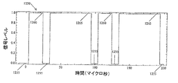
図12は、図10の信号調整器3018から現れて同じ図のアナログ−デジタル変換器(ADC)3022に入る多重化信号1300の一例を示す。このタイプの多重化信号は、位相ベースのADMによって生成することができる。図12では、より大きな振幅は測定チャネルからの信号を表し、より小さな振幅は基準チャネルからの信号を表す。基準および測定信号は、ファイバ交換網200によって一緒に多重化される。図12に示す例では、正弦波の周波数は100kHzであり、対応する期間は0.01ミリ秒=10マイクロ秒である。この例では、数値的な結果420の出力周波数は10kHzであり、対応する期間は0.1ミリ秒=100マイクロ秒である。
FIG. 12 shows an example of a multiplexed
一般に、測定および基準信号間の切換え動作により、ADM電子機器3000の電気および光学電気構成要素の出力信号にいくつかの過渡事象が現れる。ADC3022によって読み取られるこれらの過渡信号が、データ処理装置400の計算に含まれた場合、誤った結果420が生じるはずである。この問題を回避するために、データ処理装置400によって結果420を得るために処理される生データ内で過渡事象が消滅していることが重要である。
In general, due to the switching operation between the measurement and reference signals, several transients appear in the output signals of the electrical and opto-electrical components of the
ここで考慮する例では、それぞれ100マイクロ秒の期間のうちの80マイクロ秒だけが処理され、他の20マイクロ秒は破棄される。保持される80マイクロ秒のうち、20マイクロ秒(2つの正弦波期間)は基準チャネルから保持され、60マイクロ秒(6つの正弦波期間)は測定チャネルから保持される。 In the example considered here, only 80 microseconds of each 100 microsecond period are processed and the other 20 microseconds are discarded. Of the 80 microseconds held, 20 microseconds (two sine wave periods) are held from the reference channel, and 60 microseconds (6 sine wave periods) are held from the measurement channel.
図13は、電気的接続470からのタイミング信号1200を示す。タイミング信号1200が高い値1210になると測定モードが開始し、タイミング信号1200が低い値1230になると基準モードが開始する。図14は、データ460がいつ有効と見なされるかを示すゲート信号1250を示す。高いゲート信号1260は、基準信号が有効であることを示す。高いゲート信号1265は、測定信号が有効であることを示す。低いゲート信号1255は、信号が有効ではないことを示す。
FIG. 13 shows a
上記で論じたアルゴリズムの方法は、図15に示す処理システム1500を用いて実施される。処理システム1500は、追跡装置処理ユニット1510および任意選択のコンピュータ80を含む。処理ユニット1510は少なくとも1つの処理装置を含み、この処理装置は、マイクロプロセッサ、デジタル信号処理装置(DSP)、フィールドプログラム可能ゲートアレイ(FPGA)、または類似のデバイスとすることができる。情報を処理して内部追跡装置処理装置へのコマンドを発行する処理能力が提供される。そのような処理装置は、位置検出器処理装置1512、方位エンコーダ処理装置1514、天頂エンコーダ処理装置1516、表示灯処理装置1518、ADM処理装置400、干渉計(IFM)処理装置1522、およびカメラ処理装置1524を含むことができる。補助ユニット処理装置1570は、任意選択で、追跡装置処理装置ユニット1510内の他の処理装置に対してタイミングおよびマイクロプロセッサの支持を提供する。補助ユニット処理装置1570は、デバイスバス1530を用いて他の処理装置と通信することが好ましく、デバイスバス1530は、当技術分野では周知のように、データパケットを用いて追跡装置全体にわたって情報を伝達することが好ましい。追跡装置処理ユニット1510全体にわたって演算能力が分配され、DSPおよびFPGAが、追跡装置センサによって収集されたデータの中間計算を実行することが好ましい。これらの中間計算の結果は、補助ユニット処理装置1570へ戻される。補助ユニット1570は、長いケーブルによってレーザ追跡装置10の本体に取り付けることができ、または追跡装置がコンピュータ80に直接(および任意選択で)取り付けられるように、レーザ追跡装置の本体内に引き込むことができる。補助ユニット1570は接続1540によってコンピュータ80へ接続されることが好ましく、接続1540はイーサネット(登録商標)ケーブルまたは無線接続であることが好ましい。補助ユニット1570およびコンピュータ80は、接続1542、1544を通ってネットワークへ接続することができる。接続1542、1544は、イーサネット(登録商標)ケーブルまたは無線接続であることが好ましい。
The algorithmic method discussed above is implemented using a
上記の説明は、本発明の特定の実施形態を参照したが、本発明の精神から逸脱することなく、多くの変形を加えうることが理解されるであろう。添付の特許請求の範囲は、本発明の真の範囲および精神に入るはずのそのような変形を包含するものとする。 While the above description refers to particular embodiments of the invention, it will be understood that many modifications may be made without departing from the spirit of the invention. The appended claims are intended to cover such modifications as would fall within the true scope and spirit of the present invention.
したがって、本明細書に開示の実施形態は、すべての点で、限定的ではなく例示的なものとして見なされるべきであり、本発明の範囲は、上記の説明ではなく添付の特許請求の範囲によって示され、したがって、特許請求の範囲の等価の意味および範囲内に入るすべての変更は、本発明に包含されるものとする。 Accordingly, the embodiments disclosed herein are to be considered in all respects only as illustrative and not restrictive, and the scope of the present invention is not limited by the above description but by the appended claims. All changes that come within the meaning and range of equivalency of the claims are intended to be embraced by the invention.
10 レーザ追跡装置、 12 例示的なジンバル式ビームステアリング機構、 14 天頂キャリッジ、 15 ペイロード、 16 方位基部、 18 天頂機械回転軸、 20 方位機械回転軸、 22 ジンバル点、 26 外部再帰反射器、 46 レーザビーム、 48 レーザビーム、 80 コンピュータ、 102 ADMレーザ、 104 光ファイバ、 108 ADMレーザビーム、 110 可視レーザ、 112 可視レーザビーム、 114 ダイクロイックビームスプリッタ、 116 複合レーザビーム、 118 ビームスプリッタ、 126 レーザビーム、 128 光フィルタ、 130 位置検出器、 140 ADMビームコリメータ、 142 安定フェルール、 144 正レンズ、 150 可視ビーム投光器、 152 安定フェルール、 154 正レンズ、 160 ビームエキスパンダ、 162 負レンズ、 164 正レンズ、 170 追跡アセンブリ、 180 増分距離計アセンブリ、 182 安定レーザ、 184 干渉計(IFM)アセンブリ、 190 光学アセンブリ、 200 光ファイバ交換網、 200A ファイバ交換網、 200B 第2のファイバ交換網、 200C 第3のファイバ交換網、 200D 第4のファイバ交換網、 200E 第5のファイバ交換網、 204 第1の光ファイバ結合器、 206 第2の光ファイバ結合器、 208 低反射終端(LRT)、 215 光ファイバケーブル、 230 光ファイバ、 250A 追跡装置の電気光学系アセンブリ、 250B 追跡装置の電気光学系アセンブリ、 300 ADM電子機器、 310 レーザ送信器、 320 単一チャネルレーザ受信器、 322 単一検出器、 324 単一チャネル電子機器、 332 単一チャネル信号線、 330 相互接続線、 334 相互接続線、 336 相互接続線、 350 電気光学系アセンブリ、 360 電気変調信号、 400 データ処理装置、ADM処理装置、 400A データ処理装置、 402 水晶発振器、 404 水晶発振器、 410 デジタル信号処理装置、 412 位相ロックループ(PLL)デバイス、 414 カウンタ、 420 結果、位相抽出器機能、 422 補償器機能、 424 カルマンフィルタ機能、 450 ADM距離計、マイクロプロセッサ、 452 周波数分割器、 460 電気信号、電気的インターフェース、データ、 470 電気的接続、 472 タイミング電子機器、 500 光ファイバスイッチ、 501 光ファイバケーブル、 502 光ファイバ、 503 光ファイバ、 505 部分的ファイバ再帰反射器、 510 光ファイバ、 550 ADMシステム、 601 ポート、 602 ポート、 603 ポート、 610 光サーキュレータ、 650 ADMシステム、 700 ファイバスイッチ、 701 光ファイバ、 702 基準光ファイバ、 715 低反射終端、 716 光ファイバ、 750 ADMシステム、 810 ファイバスイッチ、 812 光ファイバ、 814 光ファイバ、 816 低反射終端、 820 ファイバスイッチ、 822 光ファイバ、 824 光ファイバ、 826 低反射終端、 850 ADMシステム、第4のファイバ交換網構成、 910 光変調器または減衰器、 920 光変調器または減衰器、 922 光ファイバ、 950 ADMシステム、 1200 タイミング信号、 1210 高い値、 1230 低い値、 1250 ゲート信号、 1255 低いゲート信号、 1260 高いゲート信号、 1265 高いゲート信号、 1300 多重化信号、 1500 処理システム、 1510 追跡装置処理ユニット、 1512 位置検出器処理装置、 1514 方位エンコーダ処理装置、 1516 天頂エンコーダ処理装置、 1518 表示灯処理装置、 1522 干渉計(IFM)処理装置、 1524 カメラ処理装置、 1530 デバイスバス、 1540 接続、 1542 接続、 1544 接続、 1570 補助ユニット処理装置、 2000 ADMアセンブリ、 3000 ADM電子機器、 3002 周波数基準、 3004 合成器、 3006 検出器、 3010 ミキサ、 3014 増幅器、 3018 低周波増幅器、 3022 アナログ−デジタル変換器(ADC)、 3024 周波数分割器。 10 laser tracker, 12 exemplary gimbal beam steering mechanism, 14 zenith carriage, 15 payload, 16 azimuth base, 18 zenith machine rotation axis, 20 azimuth machine rotation axis, 22 gimbal point, 26 external retroreflector, 46 laser Beam, 48 laser beam, 80 computer, 102 ADM laser, 104 optical fiber, 108 ADM laser beam, 110 visible laser, 112 visible laser beam, 114 dichroic beam splitter, 116 composite laser beam, 118 beam splitter, 126 laser beam, 128 Optical filter, 130 Position detector, 140 ADM beam collimator, 142 Stable ferrule, 144 Positive lens, 150 Visible beam projector, 152 Constant ferrule, 154 positive lens, 160 beam expander, 162 negative lens, 164 positive lens, 170 tracking assembly, 180 incremental rangefinder assembly, 182 stable laser, 184 interferometer (IFM) assembly, 190 optical assembly, 200 optical fiber exchange Network, 200A fiber switched network, 200B second fiber switched network, 200C third fiber switched network, 200D fourth fiber switched network, 200E fifth fiber switched network, 204 first optical fiber coupler, 206th 2 optical fiber coupler, 208 low reflection termination (LRT), 215 fiber optic cable, 230 optical fiber, 250A tracking device electro-optic assembly, 250B tracking device electro-optic assembly, 300 ADM Slave device, 310 laser transmitter, 320 single channel laser receiver, 322 single detector, 324 single channel electronics, 332 single channel signal line, 330 interconnect line, 334 interconnect line, 336 interconnect line 350 electro-optic assembly 360 electrical modulation signal 400 data processing device ADM processing device 400A data processing device 402 crystal oscillator 404 crystal oscillator 410 digital signal processing device 412 phase-locked loop (PLL) device 414 Counter, 420 result, phase extractor function, 422 compensator function, 424 Kalman filter function, 450 ADM distance meter, microprocessor, 452 frequency divider, 460 electrical signal, electrical interface, data, 4 0 electrical connection, 472 timing electronics, 500 optical fiber switch, 501 optical fiber cable, 502 optical fiber, 503 optical fiber, 505 partial fiber retroreflector, 510 optical fiber, 550 ADM system, 601 port, 602 port, 603 port, 610 optical circulator, 650 ADM system, 700 fiber switch, 701 optical fiber, 702 reference optical fiber, 715 low reflection termination, 716 optical fiber, 750 ADM system, 810 fiber switch, 812 optical fiber, 814 optical fiber, 816 Low reflection termination, 820 fiber switch, 822 optical fiber, 824 optical fiber, 826 low reflection termination, 850 ADM system, 4 fiber switched network configuration, 910 optical modulator or attenuator, 920 optical modulator or attenuator, 922 optical fiber, 950 ADM system, 1200 timing signal, 1210 high value, 1230 low value, 1250 gate signal, 1255 low gate Signal, 1260 high gate signal, 1265 high gate signal, 1300 multiplexed signal, 1500 processing system, 1510 tracking device processing unit, 1512 position detector processing device, 1514 azimuth encoder processing device, 1516 zenith encoder processing device, 1518 indicator light processing Device, 1522 interferometer (IFM) processing device, 1524 camera processing device, 1530 device bus, 1540 connection, 1542 connection, 1544 connection, 1570 auxiliary unit Management device, 2000 ADM assembly, 3000 ADM electronics 3002 frequency reference, 3004 synthesizer, 3006 detector, 3010 a mixer, 3014 amplifier, 3018 a low-frequency amplifier, 3022 analog - digital converter (ADC), 3024 Frequency divider.
Claims (6)
光ビームを放出するように構成された光源と、
スイッチ制御信号に応答して少なくとも2つの経路間で切り換わるように構成された少なくとも1つの第1の光スイッチを有するファイバ交換網であって、前記経路のうちの第1の経路が、前記光ビームが前記ファイバ交換網から光学ファイバの端部を通って前記ターゲットの方へ放出され、測定光ビームとして前記光学ファイバの前記端部を通って後方反射されて前記ファイバ交換網内へ戻る測定モードを可能にし、前記経路のうちの第2の経路が、前記光ビームが前記ファイバ交換網内の基準光ビームを含む基準モードを可能にする、ファイバ交換網と、
時間的に間隔を空けて多重化した形で前記測定および基準光ビームを検出するように構成され、前記検出した測定および基準光ビームに対応する電気信号を提供するように構成された単一チャネル検出器と、
前記電気信号を処理し、それに応答して調整された電気信号を提供するように構成された単一チャネル信号処理装置と、
前記スイッチ制御信号のタイミングを制御するように構成された電子部と、
前記調整された電気信号を処理して前記測定と前記基準光ビームとの位相シフトに基づいて前記ターゲットまでの前記距離を決定するように構成されたデータ処理装置と、
を含み、
前記ファイバ交換網が、
前記放出光ビームならびに前記測定および基準光ビームが通過するように構成された少なくとも1つの光ファイバ結合器と、
部分的ファイバ再帰反射器と、をさらに含み、
前記少なくとも1つの光ファイバ結合器が、前記単一チャネル検出器へ、前記光源へ、そして前記少なくとも1つの第1の光スイッチへ光学的に接続され、
前記測定モードでは、前記放出光ビームが、前記光源から前記少なくとも1つの光ファイバ結合器を通って、前記測定モード経路にある前記少なくとも1つの第1の光スイッチへ、そして前記ターゲットへ送られ、また前記ターゲットからの前記測定光ビームが、前記測定モード経路にある前記少なくとも1つの第1の光スイッチを通過し、前記少なくとも1つの光ファイバ結合器を通って前記単一チャネル検出器へ進むように構成され、
前記基準モードでは、前記放出光ビームが、前記光源から前記少なくとも1つの光ファイバ結合器を通って、前記基準モード経路にある前記少なくとも1つの第1の光スイッチへ、そして前記部分的ファイバ再帰反射器へ送られるように構成され、また前記部分的ファイバ再帰反射器から反射された前記基準光ビームが、前記基準モード経路にある前記少なくとも1つの第1の光スイッチを通過し、前記少なくとも1つの光ファイバ結合器を通って前記単一チャネル検出器へ進むように構成されることを特徴とする絶対距離計。 An absolute rangefinder configured to determine a distance to a target,
A light source configured to emit a light beam;
A fiber switched network having at least one first optical switch configured to switch between at least two paths in response to a switch control signal, wherein the first path of the paths is the optical path A measurement mode in which a beam is emitted from the fiber switching network through the end of an optical fiber toward the target and reflected back through the end of the optical fiber as a measurement light beam back into the fiber switching network A fiber switched network wherein a second path of the paths enables a reference mode in which the light beam includes a reference light beam in the fiber switched network;
A single channel configured to detect the measurement and reference light beams in a time-spaced multiplexed manner and to provide an electrical signal corresponding to the detected measurement and reference light beams A detector;
A single channel signal processing device configured to process the electrical signal and provide a conditioned electrical signal in response thereto;
An electronic unit configured to control the timing of the switch control signal;
A data processing device configured to process the adjusted electrical signal to determine the distance to the target based on a phase shift between the measurement and the reference light beam;
Including
The fiber switched network is
At least one fiber optic coupler configured to pass the emitted light beam and the measurement and reference light beams;
A partial fiber retroreflector, and
The at least one fiber optic coupler is optically connected to the single channel detector, to the light source, and to the at least one first optical switch;
In the measurement mode, the emitted light beam is sent from the light source through the at least one fiber optic coupler to the at least one first optical switch in the measurement mode path and to the target; Also, the measurement light beam from the target passes through the at least one first optical switch in the measurement mode path and travels through the at least one optical fiber coupler to the single channel detector. Composed of
In the reference mode, the emitted light beam passes from the light source through the at least one fiber optic coupler to the at least one first optical switch in the reference mode path and to the partial fiber retroreflection. And the reference light beam reflected from the partial fiber retroreflector passes through the at least one first optical switch in the reference mode path, and An absolute distance meter configured to travel through a fiber optic coupler to the single channel detector.
光ビームを放出するように構成された光源と、
スイッチ制御信号に応答して少なくとも2つの経路間で切り換わるように構成された少なくとも1つの光スイッチを有するファイバ交換網であって、前記経路のうちの第1の経路が、前記光ビームが前記ファイバ交換網から光学ファイバの端部を通って前記ターゲットの方へ放出され、測定光ビームとして前記光学ファイバの前記端部を通って後方反射されて前記ファイバ交換網内へ戻る測定モードを可能にし、前記経路のうちの第2の経路が、前記光ビームが前記ファイバ交換網内の基準光ビームを含む基準モードを可能にする、ファイバ交換網と、
時間的に間隔を空けて多重化した形で前記測定および基準光ビームを検出するように構成され、前記検出した測定および基準光ビームに対応する電気信号を提供するように構成された単一チャネル検出器と、
前記電気信号を処理し、それに応答して調整された電気信号を提供するように構成された単一チャネル信号処理装置と、
前記スイッチ制御信号のタイミングを制御するように構成された電子部と、
前記調整された電気信号を処理して前記測定と前記基準光ビームとの位相シフトに基づいて前記ターゲットまでの前記距離を決定するように構成されたデータ処理装置と、
を含み、
前記ファイバ交換網が、
前記放出光ビームならびに前記測定および基準光ビームが通過するように構成された光サーキュレータと、
部分的ファイバ再帰反射器とをさらに含み、
前記光サーキュレータが、前記単一チャネル検出器へ、前記光源へ、そして前記少なくとも1つの光スイッチへ光学的に接続され、
前記測定モードでは、前記放出光ビームが、前記光源から前記光サーキュレータを通って、前記測定モード経路にある前記少なくとも1つの光スイッチへ、そして前記ターゲットへ送られるように構成され、また前記ターゲットからの前記測定光ビームが、前記測定モード経路にある前記少なくとも1つの光スイッチを通過し、前記光サーキュレータを通って前記単一チャネル検出器へ進むように構成され、
前記基準モードでは、前記放出光ビームが、前記光源から前記光サーキュレータを通って、前記基準モード経路にある前記少なくとも1つの光スイッチへ、そして前記部分的ファイバ再帰反射器へ送られるように構成され、また前記部分的ファイバ再帰反射器から反射された前記基準光ビームが、前記基準モード経路にある前記少なくとも1つの光スイッチを通過し、前記光サーキュレータを通って前記単一チャネル検出器へ進むように構成されることを特徴とする絶対距離計。 An absolute rangefinder configured to determine a distance to a target,
A light source configured to emit a light beam;
A fiber switched network having at least one optical switch configured to switch between at least two paths in response to a switch control signal, wherein the first path of the paths includes the light beam Enables a measurement mode that is emitted from the fiber switching network through the end of the optical fiber toward the target and reflected back through the end of the optical fiber as a measurement light beam and back into the fiber switching network A fiber switched network wherein a second path of the paths enables a reference mode in which the light beam includes a reference light beam in the fiber switched network;
A single channel configured to detect the measurement and reference light beams in a time-spaced multiplexed manner and to provide an electrical signal corresponding to the detected measurement and reference light beams A detector;
A single channel signal processing device configured to process the electrical signal and provide a conditioned electrical signal in response thereto;
An electronic unit configured to control the timing of the switch control signal;
A data processing device configured to process the adjusted electrical signal to determine the distance to the target based on a phase shift between the measurement and the reference light beam;
Including
The fiber switched network is
An optical circulator configured to pass the emitted light beam and the measurement and reference light beams;
Further comprising a partial fiber retroreflector,
The optical circulator is optically connected to the single channel detector, to the light source, and to the at least one optical switch;
In the measurement mode, the emitted light beam is configured to be sent from the light source through the optical circulator to the at least one optical switch in the measurement mode path and to the target, and from the target The measurement light beam is passed through the at least one optical switch in the measurement mode path and through the optical circulator to the single channel detector;
In the reference mode, the emitted light beam is configured to be sent from the light source through the optical circulator to the at least one optical switch in the reference mode path and to the partial fiber retroreflector. And the reference light beam reflected from the partial fiber retroreflector passes through the at least one optical switch in the reference mode path and travels through the optical circulator to the single channel detector. An absolute distance meter characterized by being configured to .
光ビームを放出するように構成された光源と、
スイッチ制御信号に応答して少なくとも2つの経路間で切り換わるように構成された少なくとも1つの第1の光スイッチを有するファイバ交換網であって、前記経路のうちの第1の経路が、前記光ビームが前記ファイバ交換網から光学ファイバの端部を通って前記ターゲットの方へ放出され、測定光ビームとして前記光学ファイバの前記端部を通って後方反射されて前記ファイバ交換網内へ戻る測定モードを可能にし、前記経路のうちの第2の経路が、前記光ビームが前記ファイバ交換網内の基準光ビームを含む基準モードを可能にする、ファイバ交換網と、
時間的に間隔を空けて多重化した形で前記測定および基準光ビームを検出するように構成され、前記検出した測定および基準光ビームに対応する電気信号を提供するように構成された単一チャネル検出器と、
前記電気信号を処理し、それに応答して調整された電気信号を提供するように構成された単一チャネル信号処理装置と、
前記スイッチ制御信号のタイミングを制御するように構成された電子部と、
前記調整された電気信号を処理して前記測定と前記基準光ビームとの位相シフトに基づいて前記ターゲットまでの前記距離を決定するように構成されたデータ処理装置と、
を含み、
前記ファイバ交換網が、
前記放出光ビームならびに前記測定および基準光ビームが通過するように構成された第1および第2の光ファイバ結合器をさらに含み、
前記第1の光ファイバ結合器が、前記光源へ、前記少なくとも1つの第1の光スイッチへ、そして前記第2の光ファイバ結合器へ光学的に結合され、
前記第2の光ファイバ結合器が、前記第1の光ファイバ結合器へ、そして前記少なくとも1つの第1の光スイッチへ光学的に結合され、
前記測定モードでは、前記放出光ビームが、前記光源から前記第1の光ファイバ結合器を通り、前記第2の光ファイバ結合器を通って前記ターゲットへ送られるように構成され、また前記ターゲットからの前記測定光ビームが、前記第2の光ファイバ結合器を通過して、前記測定モード経路にある前記少なくとも1つの第1の光スイッチへ、そして前記単一チャネル検出器へ進むように構成され、
前記基準モードでは、前記放出光ビームが、前記光源から前記第1の光ファイバ結合器を通って、前記基準モード経路にある前記少なくとも1つの第1の光スイッチへ、そして前記単一チャネル検出器へ前記基準光ビームとして送られるように構成されることを特徴とする絶対距離計。 An absolute rangefinder configured to determine a distance to a target,
A light source configured to emit a light beam;
A fiber switched network having at least one first optical switch configured to switch between at least two paths in response to a switch control signal, wherein the first path of the paths is the optical path A measurement mode in which a beam is emitted from the fiber switching network through the end of an optical fiber toward the target and reflected back through the end of the optical fiber as a measurement light beam back into the fiber switching network A fiber switched network wherein a second path of the paths enables a reference mode in which the light beam includes a reference light beam in the fiber switched network;
A single channel configured to detect the measurement and reference light beams in a time-spaced multiplexed manner and to provide an electrical signal corresponding to the detected measurement and reference light beams A detector;
A single channel signal processing device configured to process the electrical signal and provide a conditioned electrical signal in response thereto;
An electronic unit configured to control the timing of the switch control signal;
A data processing device configured to process the adjusted electrical signal to determine the distance to the target based on a phase shift between the measurement and the reference light beam;
Including
The fiber switched network is
Further comprising first and second optical fiber couplers configured to pass the emitted light beam and the measurement and reference light beams;
The first optical fiber coupler is optically coupled to the light source, to the at least one first optical switch, and to the second optical fiber coupler;
Said second optical fiber coupler, said to the first fiber optic coupler, and an optical histological so coupled to the at least one first optical switch,
In the measurement mode, the emitted light beam is configured to be sent from the light source through the first optical fiber coupler, through the second optical fiber coupler to the target, and from the target. The measurement light beam is passed through the second optical fiber coupler to the at least one first optical switch in the measurement mode path and to the single channel detector. ,
In the reference mode, the emitted light beam passes from the light source through the first optical fiber coupler to the at least one first optical switch in the reference mode path and to the single channel detector. An absolute distance meter configured to be sent as the reference light beam.
光ビームを放出するように構成された光源と、
スイッチ制御信号に応答して少なくとも2つの経路間で切り換わるように構成された少なくとも1つの第1の光スイッチを有するファイバ交換網であって、前記経路のうちの第1の経路が、前記光ビームが前記ファイバ交換網から光学ファイバの端部を通って前記ターゲットの方へ放出され、測定光ビームとして前記光学ファイバの前記端部を通って後方反射されて前記ファイバ交換網内へ戻る測定モードを可能にし、前記経路のうちの第2の経路が、前記光ビームが前記ファイバ交換網内の基準光ビームを含む基準モードを可能にする、ファイバ交換網と、
時間的に間隔を空けて多重化した形で前記測定および基準光ビームを検出するように構成され、前記検出した測定および基準光ビームに対応する電気信号を提供するように構成された単一チャネル検出器と、
前記電気信号を処理し、それに応答して調整された電気信号を提供するように構成された単一チャネル信号処理装置と、
前記スイッチ制御信号のタイミングを制御するように構成された電子部と、
前記調整された電気信号を処理して前記測定と前記基準光ビームとの位相シフトに基づいて前記ターゲットまでの前記距離を決定するように構成されたデータ処理装置と、
を含み、
前記ファイバ交換網が、
前記放出光ビームならびに前記測定および基準光ビームが通過するように構成された少なくとも1つの光ファイバ結合器と、
第2および第3の光スイッチと、
部分的ファイバ再帰反射器とをさらに含み、
前記少なくとも1つの光ファイバ結合器が、前記単一チャネル検出器へ、前記光源へ、そして前記少なくとも1つの第1の光スイッチへ光学的に接続され、
前記測定モードでは、前記放出光ビームが、前記光源から前記少なくとも1つの光ファイバ結合器を通って、前記測定モード経路にある前記少なくとも1つの第1の光スイッチへ、前記測定モード経路にある前記第2の光スイッチへ、そして前記ターゲットへ送られるように構成され、また前記ターゲットからの前記測定光ビームが、前記測定モードにある前記第2の光スイッチを通過し、前記測定モード経路にある少なくとも1つの第1の光スイッチを通って、そして前記少なくとも1つの光ファイバ結合器を通って前記単一チャネル検出器へ進むように構成され、
前記基準モードでは、前記放出光ビームが、前記光源から前記少なくとも1つの光ファイバ結合器を通って、前記基準モード経路にある前記少なくとも1つの第1の光スイッチへ、前記基準モード経路にある前記第3の光スイッチへ、そして前記部分的ファイバ再帰反射器へ送られるように構成され、また前記部分的ファイバ再帰反射器から反射された前記基準光ビームが、前記基準モード経路にある前記第3の光スイッチを通過し、前記基準モード経路にある少なくとも1つの第1の光スイッチを通って、そして前記少なくとも1つの光ファイバ結合器を通って前記単一チャネル検出器へ進むように構成されることを特徴とする絶対距離計。 An absolute rangefinder configured to determine a distance to a target,
A light source configured to emit a light beam;
A fiber switched network having at least one first optical switch configured to switch between at least two paths in response to a switch control signal, wherein the first path of the paths is the optical path A measurement mode in which a beam is emitted from the fiber switching network through the end of an optical fiber toward the target and reflected back through the end of the optical fiber as a measurement light beam back into the fiber switching network A fiber switched network wherein a second path of the paths enables a reference mode in which the light beam includes a reference light beam in the fiber switched network;
A single channel configured to detect the measurement and reference light beams in a time-spaced multiplexed manner and to provide an electrical signal corresponding to the detected measurement and reference light beams A detector;
A single channel signal processing device configured to process the electrical signal and provide a conditioned electrical signal in response thereto;
An electronic unit configured to control the timing of the switch control signal;
A data processing device configured to process the adjusted electrical signal to determine the distance to the target based on a phase shift between the measurement and the reference light beam;
Including
The fiber switched network is
At least one fiber optic coupler configured to pass the emitted light beam and the measurement and reference light beams;
Second and third optical switches;
Further comprising a partial fiber retroreflector,
The at least one fiber optic coupler is optically connected to the single channel detector, to the light source, and to the at least one first optical switch;
In the measurement mode, the emitted light beam is in the measurement mode path from the light source through the at least one optical fiber coupler to the at least one first optical switch in the measurement mode path. Configured to be sent to a second optical switch and to the target, and the measurement light beam from the target passes through the second optical switch in the measurement mode and is in the measurement mode path Configured to travel through the at least one first optical switch and through the at least one fiber optic coupler to the single channel detector;
In the reference mode, the emitted light beam is in the reference mode path from the light source through the at least one optical fiber coupler to the at least one first optical switch in the reference mode path. The reference light beam configured to be sent to a third optical switch and to the partial fiber retroreflector and reflected from the partial fiber retroreflector is the third optical switch in the reference mode path. Configured to pass through the at least one optical switch, through the at least one first optical switch in the reference mode path, and through the at least one fiber optic coupler to the single channel detector. Absolute distance meter characterized by that.
光ビームを放出するように構成された光源と、
スイッチ制御信号に応答して少なくとも2つの経路間で切り換わるように構成された少なくとも1つの光スイッチを有するファイバ交換網であって、前記経路のうちの第1の経路が、前記光ビームが前記ファイバ交換網から光学ファイバの端部を通って前記ターゲットの方へ放出され、測定光ビームとして前記光学ファイバの前記端部を通って後方反射されて前記ファイバ交換網内へ戻る測定モードを可能にし、前記経路のうちの第2の経路が、前記光ビームが前記ファイバ交換網内の基準光ビームを含む基準モードを可能にする、ファイバ交換網と、
時間的に間隔を空けて多重化した形で前記測定および基準光ビームを検出するように構成され、前記検出した測定および基準光ビームに対応する電気信号を提供するように構成された単一チャネル検出器と、
前記電気信号を処理し、それに応答して調整された電気信号を提供するように構成された単一チャネル信号処理装置と、
前記スイッチ制御信号のタイミングを制御するように構成された電子部と、
前記調整された電気信号を処理して前記測定と前記基準光ビームとの位相シフトに基づいて前記ターゲットまでの前記距離を決定するように構成されたデータ処理装置と、
を含み、
前記ファイバ交換網が、
前記放出光ビームならびに前記測定および基準光ビームが通過するように構成された少なくとも1つの光ファイバ結合器と、
部分的ファイバ再帰反射器とをさらに含み、
前記少なくとも1つの光スイッチは、第1および第2の単極単投光スイッチからなり、
前記少なくとも1つの光ファイバ結合器が、前記単一チャネル検出器へ、前記光源へ、前記第1の単極単投光スイッチへ、そして前記第2の単極単投光スイッチへ光学的に接続され、
前記測定モードでは、前記放出光ビームが、前記光源から前記少なくとも1つの光ファイバ結合器を通って、前記測定モード経路にある前記第1の単極単投光スイッチへ、そして前記ターゲットへ送られるように構成され、また前記ターゲットからの前記測定光ビームが、前記測定モード経路にある前記第1の単極単投光スイッチを通過し、前記少なくとも1つの光ファイバ結合器を通って前記単一チャネル検出器へ進むように構成され、
前記基準モードでは、前記放出光ビームが、前記光源から前記少なくとも1つの第1の光ファイバ結合器を通って、前記基準モード経路にある前記第2の単極単投光スイッチへ、そして前記部分的ファイバ再帰反射器へ送られるように構成され、また前記部分的ファイバ再帰反射器から反射された前記基準光ビームが、前記基準モード経路にある前記第2の単極単投光スイッチを通過し、前記少なくとも1つの光ファイバ結合器を通って前記単一チャネル検出器へ進むように構成されることを特徴とする絶対距離計。 An absolute rangefinder configured to determine a distance to a target,
A light source configured to emit a light beam;
A fiber switched network having at least one optical switch configured to switch between at least two paths in response to a switch control signal, wherein the first path of the paths includes the light beam Enables a measurement mode that is emitted from the fiber switching network through the end of the optical fiber toward the target and reflected back through the end of the optical fiber as a measurement light beam and back into the fiber switching network A fiber switched network wherein a second path of the paths enables a reference mode in which the light beam includes a reference light beam in the fiber switched network;
A single channel configured to detect the measurement and reference light beams in a time-spaced multiplexed manner and to provide an electrical signal corresponding to the detected measurement and reference light beams A detector;
A single channel signal processing device configured to process the electrical signal and provide a conditioned electrical signal in response thereto;
An electronic unit configured to control the timing of the switch control signal;
A data processing device configured to process the adjusted electrical signal to determine the distance to the target based on a phase shift between the measurement and the reference light beam;
Including
The fiber switched network is
At least one fiber optic coupler configured to pass the emitted light beam and the measurement and reference light beams ;
Further comprising a partial fiber retroreflector,
The at least one optical switch comprises first and second single-pole single-projection switches;
The at least one fiber optic coupler is optically connected to the single channel detector, to the light source, to the first single pole single flood switch, and to the second single pole single flood switch And
In the measurement mode, the emitted light beam is sent from the light source through the at least one fiber optic coupler to the first single-pole single-projection switch in the measurement mode path and to the target. And the measurement light beam from the target passes through the first single-pole single-projection switch in the measurement mode path, passes through the at least one optical fiber coupler, and the single Configured to go to the channel detector,
In the reference mode, the emitted light beam passes from the light source through the at least one first fiber optic coupler to the second single-pole single-projection switch in the reference mode path, and the portion. And the reference light beam reflected from the partial fiber retroreflector passes through the second single pole single throw switch in the reference mode path. An absolute distance meter configured to travel through the at least one fiber optic coupler to the single channel detector.
6. The absolute distance meter according to claim 5, wherein the first single-pole single-projection switch and the second single-pole single-projection switch are each between a first minimum level and a second maximum level. absolute distance meter, wherein the configured optical modulator or attenuator as driven including it in.
Applications Claiming Priority (2)
| Application Number | Priority Date | Filing Date | Title |
|---|---|---|---|
| US23222209P | 2009-08-07 | 2009-08-07 | |
| US61/232,222 | 2009-08-07 |
Publications (3)
| Publication Number | Publication Date |
|---|---|
| JP2011039052A JP2011039052A (en) | 2011-02-24 |
| JP2011039052A5 JP2011039052A5 (en) | 2012-10-25 |
| JP5401412B2 true JP5401412B2 (en) | 2014-01-29 |
Family
ID=42931252
Family Applications (1)
| Application Number | Title | Priority Date | Filing Date |
|---|---|---|---|
| JP2010176909A Expired - Fee Related JP5401412B2 (en) | 2009-08-07 | 2010-08-06 | Absolute distance meter with optical switch |
Country Status (5)
| Country | Link |
|---|---|
| US (1) | US8659749B2 (en) |
| JP (1) | JP5401412B2 (en) |
| CN (1) | CN101995577A (en) |
| DE (1) | DE102010038955B4 (en) |
| GB (1) | GB2472514B (en) |
Families Citing this family (49)
| Publication number | Priority date | Publication date | Assignee | Title |
|---|---|---|---|---|
| US9482755B2 (en) | 2008-11-17 | 2016-11-01 | Faro Technologies, Inc. | Measurement system having air temperature compensation between a target and a laser tracker |
| US8659749B2 (en) | 2009-08-07 | 2014-02-25 | Faro Technologies, Inc. | Absolute distance meter with optical switch |
| US9400170B2 (en) | 2010-04-21 | 2016-07-26 | Faro Technologies, Inc. | Automatic measurement of dimensional data within an acceptance region by a laser tracker |
| US9377885B2 (en) | 2010-04-21 | 2016-06-28 | Faro Technologies, Inc. | Method and apparatus for locking onto a retroreflector with a laser tracker |
| US9772394B2 (en) | 2010-04-21 | 2017-09-26 | Faro Technologies, Inc. | Method and apparatus for following an operator and locking onto a retroreflector with a laser tracker |
| US8619265B2 (en) | 2011-03-14 | 2013-12-31 | Faro Technologies, Inc. | Automatic measurement of dimensional data with a laser tracker |
| US8902408B2 (en) | 2011-02-14 | 2014-12-02 | Faro Technologies Inc. | Laser tracker used with six degree-of-freedom probe having separable spherical retroreflector |
| GB2518544A (en) | 2011-03-03 | 2015-03-25 | Faro Tech Inc | Target apparatus and method |
| US9164173B2 (en) | 2011-04-15 | 2015-10-20 | Faro Technologies, Inc. | Laser tracker that uses a fiber-optic coupler and an achromatic launch to align and collimate two wavelengths of light |
| US9482529B2 (en) | 2011-04-15 | 2016-11-01 | Faro Technologies, Inc. | Three-dimensional coordinate scanner and method of operation |
| US9686532B2 (en) | 2011-04-15 | 2017-06-20 | Faro Technologies, Inc. | System and method of acquiring three-dimensional coordinates using multiple coordinate measurement devices |
| DE112012001708B4 (en) | 2011-04-15 | 2018-05-09 | Faro Technologies, Inc. | coordinate measuring machine |
| USD688577S1 (en) | 2012-02-21 | 2013-08-27 | Faro Technologies, Inc. | Laser tracker |
| DE112013000727T5 (en) | 2012-01-27 | 2014-11-06 | Faro Technologies, Inc. | Test method with bar code marking |
| US8937725B2 (en) | 2012-06-14 | 2015-01-20 | Nikon Corporation | Measurement assembly including a metrology system and a pointer that directs the metrology system |
| US9823351B2 (en) * | 2012-12-18 | 2017-11-21 | Uber Technologies, Inc. | Multi-clad fiber based optical apparatus and methods for light detection and ranging sensors |
| JP5627719B2 (en) * | 2013-01-16 | 2014-11-19 | 三菱重工業株式会社 | Target holding jig and measuring device |
| US9746560B2 (en) | 2013-02-12 | 2017-08-29 | Faro Technologies, Inc. | Combination scanner and tracker device having a focusing mechanism |
| US9036134B2 (en) * | 2013-02-12 | 2015-05-19 | Faro Technologies, Inc. | Multi-mode optical measurement device and method of operation |
| US9417062B2 (en) | 2013-02-15 | 2016-08-16 | Andrew P. Thierwechter | Forensic mapping instrument |
| US9188430B2 (en) | 2013-03-14 | 2015-11-17 | Faro Technologies, Inc. | Compensation of a structured light scanner that is tracked in six degrees-of-freedom |
| US9046360B2 (en) | 2013-03-14 | 2015-06-02 | Faro Technologies, Inc. | System and method of acquiring three dimensional coordinates using multiple coordinate measurement devices |
| US9041914B2 (en) | 2013-03-15 | 2015-05-26 | Faro Technologies, Inc. | Three-dimensional coordinate scanner and method of operation |
| US9113154B2 (en) | 2013-07-10 | 2015-08-18 | Faro Technologies, Inc. | Three-dimensional measurement device having three-dimensional overview camera |
| US9347767B2 (en) | 2013-12-11 | 2016-05-24 | Faro Technologies, Inc. | Spherically mounted retroreflector and method to minimize measurement error |
| US9423492B2 (en) | 2013-12-11 | 2016-08-23 | Faro Technologies, Inc. | Method for finding a home reference distance using a spherically mounted retroreflector |
| US9329028B2 (en) | 2013-12-11 | 2016-05-03 | Faro Technologies, Inc. | Spherically mounted retroreflector having an embedded temperature sensor and socket |
| US9239238B2 (en) * | 2013-12-11 | 2016-01-19 | Faro Technologies, Inc. | Method for correcting a 3D measurement of a spherically mounted retroreflector on a nest |
| US9606235B2 (en) * | 2014-01-16 | 2017-03-28 | The Boeing Company | Laser metrology system and method |
| RU2558694C1 (en) * | 2014-06-09 | 2015-08-10 | Открытое акционерное общество "Научно-исследовательский институт "Полюс" им. М.Ф. Стельмаха" | Determination of aircraft altitude |
| US9395174B2 (en) | 2014-06-27 | 2016-07-19 | Faro Technologies, Inc. | Determining retroreflector orientation by optimizing spatial fit |
| WO2016118637A1 (en) | 2015-01-20 | 2016-07-28 | Volfson Leo | Single aperture laser range finder |
| WO2016190921A1 (en) * | 2015-02-05 | 2016-12-01 | Associated Universities, Inc. | Fiber optic based laser range finder |
| DE102016107312A1 (en) * | 2015-04-28 | 2016-11-03 | Faro Technologies Inc. | Combined scanner and tracker with a focusing mechanism |
| US10145671B2 (en) | 2016-03-31 | 2018-12-04 | Topcon Positioning Systems, Inc. | Three dimensional laser measuring system and method |
| TWI595252B (en) * | 2016-05-10 | 2017-08-11 | 財團法人工業技術研究院 | Distance measurement device and distance measuring method thereof |
| JP6857979B2 (en) * | 2016-07-27 | 2021-04-14 | 株式会社トプコン | Laser scanner optics and surveying equipment |
| US9948395B2 (en) * | 2016-09-12 | 2018-04-17 | The United States Of America As Represented By Secretary Of The Navy | System and method for line-of-sight optical broadcasting using beam divergence and an orbiting or airborne corner cube reflector |
| US10284836B2 (en) | 2017-02-08 | 2019-05-07 | Microsoft Technology Licensing, Llc | Depth camera light leakage avoidance |
| KR102353513B1 (en) * | 2017-03-16 | 2022-01-20 | 주식회사 히타치엘지 데이터 스토리지 코리아 | Rotary distance measuring apparatus |
| KR102061040B1 (en) * | 2018-02-02 | 2019-12-31 | 호서대학교 산학협력단 | Invisible LiDAR or Laser Scanning Apparatus |
| WO2020030271A1 (en) * | 2018-08-09 | 2020-02-13 | Fraunhofer-Gesellschaft zur Förderung der angewandten Forschung e.V. | Lidar and method for optical remote sensing |
| CN109188367B (en) * | 2018-09-03 | 2022-11-22 | 西安电子工程研究所 | Circuit structure capable of realizing power amplification link fault emergency replacement function |
| JP7208388B2 (en) * | 2018-11-13 | 2023-01-18 | ブラックモア センサーズ アンド アナリティクス エルエルシー | Laser phase tracking method and system for internal reflection subtraction in phase-encoding LIDAR |
| US11493695B2 (en) * | 2019-06-25 | 2022-11-08 | Thomas C. Stewart | Sustained continuity non-powered optomechanical position switch utilizing self-testing multiplexed optocontrolling transceiver in a fiber-optic circuit |
| US11709237B2 (en) * | 2020-06-30 | 2023-07-25 | Luminar Technologies, Inc. | LiDAR systems and methods |
| CN112556579A (en) * | 2020-12-25 | 2021-03-26 | 深圳市中图仪器股份有限公司 | Six-degree-of-freedom space coordinate position and attitude measuring device |
| CN112803897B (en) * | 2020-12-30 | 2022-11-18 | 四川德骏智造科技有限公司 | Terahertz fundamental wave frequency mixing module |
| TWI750985B (en) * | 2020-12-31 | 2021-12-21 | 艾創科技股份有限公司 | Laser ranging device |
Family Cites Families (147)
| Publication number | Priority date | Publication date | Assignee | Title |
|---|---|---|---|---|
| US2682804A (en) | 1950-09-26 | 1954-07-06 | Taylor Taylor & Hobson Ltd | Optical micrometer for alignment telescopes |
| US2784641A (en) | 1952-06-20 | 1957-03-12 | Keuffel & Esser Co | Alignment telescope |
| US3497695A (en) | 1961-12-11 | 1970-02-24 | Raytheon Co | Radiant energy transmitting device |
| GB1104021A (en) | 1963-11-11 | 1968-02-21 | Nat Res Dev | Distance measuring apparatus |
| LU46404A1 (en) | 1964-06-26 | 1972-01-01 | ||
| DE1210360B (en) | 1964-11-07 | 1966-02-03 | Leitz Ernst Gmbh | Sighting device coupled to a laser range finder |
| US3365717A (en) | 1965-09-03 | 1968-01-23 | South African Inventions | Method of and apparatus for providing a measure of the distance between two spaced points |
| US3627429A (en) | 1968-08-14 | 1971-12-14 | Spectra Physics | Laser optical surveying instrument and method |
| US3658426A (en) | 1968-09-11 | 1972-04-25 | Itek Corp | Alignment telescope |
| US3619058A (en) | 1969-11-24 | 1971-11-09 | Hewlett Packard Co | Distance measuring apparatus |
| US3779645A (en) | 1970-05-20 | 1973-12-18 | Nippon Kogaku Kk | Distance measuring device |
| US3728025A (en) | 1971-03-08 | 1973-04-17 | Cubic Corp | Optical distance measuring equipment |
| US3813165A (en) | 1971-09-20 | 1974-05-28 | Laser Syst & Electronics Inc | Digital distance measuring apparatus employing modulated light beam |
| US3740141A (en) | 1971-09-20 | 1973-06-19 | Laser Systems & Electronics | Timing and measuring methods and means for laser distance measurements |
| US3832056A (en) | 1972-03-13 | 1974-08-27 | Aga Corp | Distance measuring device using electro-optical techniques |
| DE2553691C2 (en) | 1975-11-28 | 1986-10-30 | MITEC Moderne Industrietechnik GmbH, 8012 Ottobrunn | Method for opto-electronic measurement of the distance between a measuring point and a target point and a distance measuring device for carrying out this method |
| DE2235318C3 (en) | 1972-07-19 | 1980-02-14 | Ito-Patent Ag, Zuerich (Schweiz) | Method for opto-electronic measurement of distance and height difference and arrangement for carrying out the method |
| FR2206510A1 (en) | 1972-11-15 | 1974-06-07 | Aga Ab | |
| US4113381A (en) | 1976-11-18 | 1978-09-12 | Hewlett-Packard Company | Surveying instrument and method |
| GB2066015B (en) | 1979-10-23 | 1984-02-15 | South African Inventions | Distance measurment |
| US4453825A (en) | 1979-12-07 | 1984-06-12 | Hewlett-Packard Company | Distance transducer |
| DE3103567A1 (en) | 1981-02-03 | 1982-08-12 | MITEC Moderne Industrietechnik GmbH, 8012 Ottobrunn | DISTANCE MEASURING METHOD ACCORDING TO THE PRINCIPLE OF THE RUNTIME MEASUREMENT OF A MEASURING LIGHT IMPULSE AND DEVICE FOR ITS IMPLEMENTATION |
| ZA824061B (en) * | 1981-06-09 | 1983-04-27 | L Bolkow | Distance measurement method and apparatus for its performance |
| US4498764A (en) * | 1981-06-09 | 1985-02-12 | Ludwig Bolkow | Dynamic control arrangement for a distance measuring apparatus |
| DE3219423C2 (en) | 1981-06-09 | 1986-04-30 | MTC, Meßtechnik und Optoelektronik AG, Neuenburg/Neuchâtel | Distance measuring method and device for its implementation |
| JPS5838880A (en) | 1981-08-31 | 1983-03-07 | Tokyo Optical Co Ltd | Light wave range finder |
| DE3371561D1 (en) | 1982-08-26 | 1987-06-19 | Shell Int Research | A method and apparatus for tank gauging using diode lasers and optical fibres |
| US4692023A (en) * | 1983-07-30 | 1987-09-08 | Tokyo Kagaku Kikai Kabushiki Kaisha | Optical adapter for a light-wave rangefinder |
| JPS6097288A (en) * | 1983-11-01 | 1985-05-31 | Toshiba Corp | Distance measuring apparatus |
| JPS60237307A (en) | 1984-05-11 | 1985-11-26 | Yokogawa Hewlett Packard Ltd | Laser length measuring machine |
| US4632547A (en) | 1985-09-10 | 1986-12-30 | Broomer Research Corporation | Autocollimating alignment telescope |
| US4714339B2 (en) | 1986-02-28 | 2000-05-23 | Us Commerce | Three and five axis laser tracking systems |
| US4790651A (en) | 1987-09-30 | 1988-12-13 | Chesapeake Laser Systems, Inc. | Tracking laser interferometer |
| SE464782B (en) | 1987-12-22 | 1991-06-10 | Geotronics Ab | DEVICE FOR A DISTANCE SEATING INSTRUMENT SUCH AS AID TO EXPOSURE |
| JP2717408B2 (en) | 1988-03-16 | 1998-02-18 | 株式会社トプコン | Lightwave ranging device with linearity error correction function |
| DE3827458C3 (en) | 1988-08-12 | 1998-04-09 | Michael H Dipl Ing Korte | Method and device for determining the spatial coordinates of any measuring point |
| JP2731565B2 (en) * | 1989-01-11 | 1998-03-25 | 松下電工株式会社 | Distance sensor |
| GB9003221D0 (en) | 1990-02-13 | 1990-04-11 | Optical Measuring Systems Limi | Electronic distance measurement |
| US5082364A (en) | 1990-08-31 | 1992-01-21 | Russell James T | Rf modulated optical beam distance measuring system and method |
| JP3132894B2 (en) * | 1992-04-24 | 2001-02-05 | 工業技術院長 | Distance measuring device |
| JP2584875Y2 (en) | 1992-05-26 | 1998-11-11 | 株式会社ニコン | Lightwave ranging device |
| US5319434A (en) | 1992-12-30 | 1994-06-07 | Litton Systems, Inc. | Laser rangefinder apparatus with fiber optic interface |
| JP3268608B2 (en) | 1993-02-12 | 2002-03-25 | 株式会社トプコン | Surveying equipment |
| US5416321A (en) | 1993-04-08 | 1995-05-16 | Coleman Research Corporation | Integrated apparatus for mapping and characterizing the chemical composition of surfaces |
| US5455670A (en) | 1993-05-27 | 1995-10-03 | Associated Universities, Inc. | Optical electronic distance measuring apparatus with movable mirror |
| US5402193A (en) | 1993-08-30 | 1995-03-28 | Optical Gaging Products, Inc. | Method and means for projecting images in a contour projector |
| JP3307730B2 (en) | 1993-08-30 | 2002-07-24 | 浜松ホトニクス株式会社 | Optical measuring device |
| DE4438955C2 (en) | 1994-10-31 | 1996-09-26 | Swarovski Optik Kg | Rifle scope |
| JPH08220232A (en) | 1995-02-08 | 1996-08-30 | Asahi Optical Co Ltd | Light wave range finding device and optical path switching method in light wave range finding device |
| JP3523368B2 (en) | 1995-05-12 | 2004-04-26 | ペンタックス株式会社 | Lightwave rangefinder |
| DE19542490C1 (en) | 1995-11-15 | 1997-06-05 | Leica Ag | Electro-optical measuring device for absolute distances |
| US5742379A (en) | 1995-11-29 | 1998-04-21 | Reifer; Michael H. | Device and method for electronically measuring distances |
| JPH09236662A (en) | 1996-02-29 | 1997-09-09 | Ushikata Shokai:Kk | Electronic distance meter |
| US5892575A (en) * | 1996-05-10 | 1999-04-06 | Massachusetts Institute Of Technology | Method and apparatus for imaging a scene using a light detector operating in non-linear geiger-mode |
| US5754284A (en) | 1996-10-09 | 1998-05-19 | Exfo Electro-Optical Engineering Inc. | Optical time domain reflectometer with internal reference reflector |
| DE19643287A1 (en) | 1996-10-21 | 1998-04-23 | Leica Ag | Method and device for calibrating distance measuring devices |
| DE19647152A1 (en) | 1996-11-14 | 1998-05-28 | Sick Ag | Laser distance determination device |
| EP1004051A1 (en) * | 1997-08-01 | 2000-05-31 | Akzo Nobel N.V. | Cascaded optical switch comprising at least one gate |
| JP3569426B2 (en) | 1997-12-05 | 2004-09-22 | ペンタックス株式会社 | Reflecting member for surveying |
| JPH11337642A (en) * | 1998-05-26 | 1999-12-10 | Nikon Corp | Light wave distance measuring device |
| US6351483B1 (en) | 1998-06-29 | 2002-02-26 | Quarton, Inc. | Laser optical axis correcting method |
| DE19855296C1 (en) | 1998-12-01 | 2000-08-31 | Bosch Gmbh Robert | Device for distance measurement using a semiconductor laser in the visible wavelength range using the transit time method |
| US6100540A (en) | 1999-02-22 | 2000-08-08 | Visidyne, Inc. | Laser displacement measurement system |
| US6400540B1 (en) * | 1999-03-12 | 2002-06-04 | Sil.Able Inc. | Clamp circuit to prevent ESD damage to an integrated circuit |
| USD427087S (en) | 1999-03-19 | 2000-06-27 | Asahi Seimitsu Kabushiki Kaisha | Measurement surveying device |
| US7800758B1 (en) | 1999-07-23 | 2010-09-21 | Faro Laser Trackers, Llc | Laser-based coordinate measuring device and laser-based method for measuring coordinates |
| AT407202B (en) | 1999-06-10 | 2001-01-25 | Perger Andreas Dr | COMBINED SCOPE AND DISTANCE MEASURING DEVICE |
| JP2001021354A (en) | 1999-07-09 | 2001-01-26 | Topcon Corp | Optical position detector |
| US6490027B1 (en) | 1999-07-27 | 2002-12-03 | Suzanne K. Rajchel | Reduced noise optical system and method for measuring distance |
| DE10006493C2 (en) | 2000-02-14 | 2002-02-07 | Hilti Ag | Method and device for optoelectronic distance measurement |
| JP2001272468A (en) | 2000-03-27 | 2001-10-05 | Nikon Corp | Optical waveguide device and light wave distance measuring equipment |
| GB0008303D0 (en) | 2000-04-06 | 2000-05-24 | British Aerospace | Measurement system and method |
| JP3881498B2 (en) | 2000-05-25 | 2007-02-14 | ペンタックス株式会社 | Light wave rangefinder |
| WO2002016964A1 (en) | 2000-08-25 | 2002-02-28 | Kurt Giger | Method and device for measuring distances |
| US6563569B2 (en) | 2000-09-25 | 2003-05-13 | Agency Of Industrial Science & Technology, Ministry Of International Trade & Industry | Laser tracking interferometric length measuring instrument and method of measuring length and coordinates using the same |
| JP2002098762A (en) | 2000-09-26 | 2002-04-05 | Nikon Corp | Electro-optical distance measuring instrument |
| ATE447723T1 (en) | 2000-09-27 | 2009-11-15 | Leica Geosystems Ag | DEVICE AND METHOD FOR SIGNAL DETECTION IN A DISTANCE MEASUREMENT DEVICE |
| JP3935841B2 (en) | 2000-11-30 | 2007-06-27 | ライカ・ジオシステムズ・アーゲー | Frequency synthesizing method and apparatus for rangefinder, and rangefinder |
| ATE491961T1 (en) | 2001-04-10 | 2011-01-15 | Faro Tech Inc | CHOPPER STABILIZED ABSOLUTE DISTANCE MEASUREMENT DEVICE |
| US7505119B2 (en) * | 2001-04-13 | 2009-03-17 | Optical Air Data Systems, Llc | Multi-function optical system and assembly |
| EP1476797B1 (en) | 2001-10-11 | 2012-11-21 | Laser Projection Technologies, Inc. | Method and system for visualizing surface errors |
| EP1466136B1 (en) | 2002-01-16 | 2011-08-03 | Faro Technologies, Inc. | Laser-based coordinate measuring device and laser-based method for measuring coordinates |
| AU2003217687A1 (en) | 2002-02-22 | 2003-09-09 | Faro Laser Trackers, Llc | Spherically mounted light source with angle measuring device, tracking system, and method for determining coordinates |
| WO2003089949A2 (en) | 2002-04-15 | 2003-10-30 | Toolz, Ltd. | Distance measurement device with short distance optics |
| DE10235562A1 (en) | 2002-08-03 | 2004-02-19 | Robert Bosch Gmbh | Optical distance measurement device has a measurement diode, which is used for reflected signal detection and frequency conversion to a lower frequency, that has high frequency modulated electrode voltages |
| EP1388739A1 (en) | 2002-08-09 | 2004-02-11 | HILTI Aktiengesellschaft | Laser range finder with phase difference measurement |
| DE10239448A1 (en) | 2002-08-28 | 2005-06-16 | Robert Bosch Gmbh | Distance measuring Equipment |
| JP4104991B2 (en) | 2003-01-16 | 2008-06-18 | 株式会社トプコン | Light wave distance meter |
| JP4301863B2 (en) | 2003-05-21 | 2009-07-22 | 株式会社トプコン | Ranging device |
| EP2405284B1 (en) | 2003-09-05 | 2014-03-05 | Faro Technologies, Inc. | Self-compensating laser tracker |
| EP1719580B1 (en) | 2003-09-10 | 2012-06-27 | Nikon Metrology NV | Laser projection system |
| US7384220B2 (en) | 2004-01-06 | 2008-06-10 | The Boeing Company | Laser-guided coordination hole drilling |
| JP4832720B2 (en) | 2004-01-29 | 2011-12-07 | 株式会社トプコン | Pulse signal processing apparatus, pulse signal processing method and program |
| JP3935897B2 (en) | 2004-06-15 | 2007-06-27 | 北陽電機株式会社 | Lightwave ranging device |
| US20080316503A1 (en) | 2004-09-08 | 2008-12-25 | Smarsh Steven G | Automated Inspection Comparator/Shadowgraph System |
| US7352446B2 (en) * | 2004-09-30 | 2008-04-01 | Faro Technologies, Inc. | Absolute distance meter that measures a moving retroreflector |
| JP4830096B2 (en) | 2004-09-30 | 2011-12-07 | 国立大学法人名古屋大学 | Distance measuring device and distance measuring method |
| JP4707363B2 (en) | 2004-10-20 | 2011-06-22 | 株式会社 ソキア・トプコン | Light wave distance meter |
| US7268893B2 (en) | 2004-11-12 | 2007-09-11 | The Boeing Company | Optical projection system |
| US7701592B2 (en) | 2004-12-17 | 2010-04-20 | The Boeing Company | Method and apparatus for combining a targetless optical measurement function and optical projection of information |
| DE102004061338B4 (en) | 2004-12-20 | 2011-12-29 | Steinbichler Optotechnik Gmbh | Automatic component testing |
| CN1815212B (en) | 2005-02-05 | 2010-06-16 | 香港中文大学 | Diagnosis method for metal punching course and apparatus thereof |
| DE102005007916A1 (en) | 2005-02-10 | 2006-08-17 | Hensoldt Ag | Scope with a rangefinder |
| US7511824B2 (en) * | 2005-02-14 | 2009-03-31 | Digital Signal Corporation | Chirped coherent laser radar system and method |
| WO2007086888A2 (en) | 2005-03-04 | 2007-08-02 | Cornell Research Foundation, Inc. | Electro-optic modulation |
| JP4819403B2 (en) | 2005-06-06 | 2011-11-24 | 株式会社トプコン | Distance measuring device |
| JP4828167B2 (en) | 2005-06-16 | 2011-11-30 | 株式会社 ソキア・トプコン | Distance measuring apparatus and method |
| WO2007002319A1 (en) | 2005-06-23 | 2007-01-04 | Faro Technologies, Inc. | Apparatus and method for relocating an articulating-arm coordinate measuring machine |
| US7285793B2 (en) | 2005-07-15 | 2007-10-23 | Verisurf Software, Inc. | Coordinate tracking system, apparatus and method of use |
| US7392592B2 (en) | 2005-10-07 | 2008-07-01 | Milwaukee Electric Tool Corporation | Ruggedized laser level |
| WO2007084209A2 (en) | 2005-11-10 | 2007-07-26 | Optical Air Data Systems, Llc | Single aperture multiple optical waveguide transceiver |
| US7511800B2 (en) | 2005-11-28 | 2009-03-31 | Robert Bosch Company Limited | Distance measurement device with short range optics |
| US7480037B2 (en) | 2005-12-02 | 2009-01-20 | The Boeing Company | System for projecting flaws and inspection locations and associated method |
| TWI287622B (en) | 2006-03-02 | 2007-10-01 | Asia Optical Co Inc | Phase measurement method and application |
| DE102006013290A1 (en) | 2006-03-23 | 2007-09-27 | Robert Bosch Gmbh | Device for optical distance measurement and method for operating such a device |
| DE602007010753D1 (en) | 2006-04-21 | 2011-01-05 | Faro Tech Inc | CAMERA-DRIVEN DEVICE FOR TARGET MEASUREMENT AND TARGET TRACKING WITH SIX FREEDOM RATES AND ROTATABLE MIRROR |
| DE202006020299U1 (en) | 2006-05-16 | 2008-04-24 | Deutsches Zentrum für Luft- und Raumfahrt e.V. | 3D measurement arrangement |
| TWI288230B (en) | 2006-08-10 | 2007-10-11 | Asia Optical Co Inc | Laser ranging system with a shutter mechanism |
| JP2010502953A (en) | 2006-08-31 | 2010-01-28 | ファロ テクノロジーズ インコーポレーテッド | Intelligent probe |
| US7256899B1 (en) | 2006-10-04 | 2007-08-14 | Ivan Faul | Wireless methods and systems for three-dimensional non-contact shape sensing |
| US8087315B2 (en) | 2006-10-10 | 2012-01-03 | Honeywell International Inc. | Methods and systems for attaching and detaching a payload device to and from, respectively, a gimbal system without requiring use of a mechanical tool |
| WO2008052348A1 (en) | 2006-11-02 | 2008-05-08 | Northern Digital Inc. | Integrated mapping system |
| US7586586B2 (en) | 2007-01-19 | 2009-09-08 | Associates Universities, Inc. | Fiber optically coupled, multiplexed, and chopped laser rangefinder |
| JP5137104B2 (en) | 2007-03-22 | 2013-02-06 | 株式会社 ソキア・トプコン | Light wave distance meter |
| US20080246974A1 (en) | 2007-03-28 | 2008-10-09 | Jean Laurent Wilson | Portable Optical Measurement Assembly |
| WO2008121919A1 (en) | 2007-03-30 | 2008-10-09 | Faro Technologies, Inc. | Absolute distance meter |
| US7835012B1 (en) | 2007-05-01 | 2010-11-16 | Lockheed Martin Corporation | Alignment interferometer telescope apparatus and method |
| JP5244339B2 (en) | 2007-06-20 | 2013-07-24 | 株式会社ミツトヨ | Tracking laser interferometer and recovery method of tracking laser interferometer |
| KR100832696B1 (en) | 2008-01-18 | 2008-05-28 | 임권현 | Vacuum chuck |
| US7738083B2 (en) | 2008-02-05 | 2010-06-15 | Asia Optical Co., Inc. | Distant measurement method and distant measurement system |
| WO2009113484A1 (en) | 2008-03-11 | 2009-09-17 | 株式会社ニコン | Reference sphere detecting device, reference sphere position detecting device, and three-dimensional coordinate measuring device |
| USD605959S1 (en) | 2008-07-23 | 2009-12-15 | Leica Geosystems Ag | Land surveying total station measuring device |
| TW201009650A (en) | 2008-08-28 | 2010-03-01 | Acer Inc | Gesture guide system and method for controlling computer system by gesture |
| US7908757B2 (en) | 2008-10-16 | 2011-03-22 | Hexagon Metrology, Inc. | Articulating measuring arm with laser scanner |
| DE112009005524B3 (en) | 2008-11-17 | 2018-01-25 | Faro Technologies, Inc. | Apparatus and method for measuring six degrees of freedom |
| US8803055B2 (en) | 2009-01-09 | 2014-08-12 | Automated Precision Inc. | Volumetric error compensation system with laser tracker and active target |
| US8861833B2 (en) | 2009-02-18 | 2014-10-14 | International Press Of Boston, Inc. | Simultaneous three-dimensional geometry and color texture acquisition using single color camera |
| US8717545B2 (en) | 2009-02-20 | 2014-05-06 | Digital Signal Corporation | System and method for generating three dimensional images using lidar and video measurements |
| US8339616B2 (en) | 2009-03-31 | 2012-12-25 | Micrometric Vision Technologies | Method and apparatus for high-speed unconstrained three-dimensional digitalization |
| USD629314S1 (en) | 2009-04-23 | 2010-12-21 | Nikon-Trimble Co., Ltd. | Electronic tacheometer |
| EP2259013B1 (en) | 2009-05-25 | 2013-11-20 | Siemens Aktiengesellschaft | Topographical measurement of an object |
| EP2446299B1 (en) | 2009-06-23 | 2016-08-10 | Leica Geosystems AG | Coordinate measuring device |
| US8659749B2 (en) | 2009-08-07 | 2014-02-25 | Faro Technologies, Inc. | Absolute distance meter with optical switch |
| US20110069322A1 (en) | 2009-09-21 | 2011-03-24 | Faro Technologies, Inc. | Laser pointing mechanism |
| WO2011090892A2 (en) | 2010-01-20 | 2011-07-28 | Faro Technologies, Inc. | Coordinate measurement machines with removable accessories |
| US8422034B2 (en) | 2010-04-21 | 2013-04-16 | Faro Technologies, Inc. | Method and apparatus for using gestures to control a laser tracker |
| DE112012001708B4 (en) | 2011-04-15 | 2018-05-09 | Faro Technologies, Inc. | coordinate measuring machine |
-
2010
- 2010-08-03 US US12/849,065 patent/US8659749B2/en active Active
- 2010-08-05 GB GB1013200A patent/GB2472514B/en not_active Expired - Fee Related
- 2010-08-05 DE DE102010038955.2A patent/DE102010038955B4/en not_active Expired - Fee Related
- 2010-08-06 JP JP2010176909A patent/JP5401412B2/en not_active Expired - Fee Related
- 2010-08-09 CN CN2010102511893A patent/CN101995577A/en active Pending
Also Published As
| Publication number | Publication date |
|---|---|
| DE102010038955B4 (en) | 2019-08-01 |
| GB2472514B (en) | 2011-08-03 |
| GB2472514A (en) | 2011-02-09 |
| US20110032509A1 (en) | 2011-02-10 |
| JP2011039052A (en) | 2011-02-24 |
| US8659749B2 (en) | 2014-02-25 |
| CN101995577A (en) | 2011-03-30 |
| GB201013200D0 (en) | 2010-09-22 |
| DE102010038955A1 (en) | 2011-02-24 |
Similar Documents
| Publication | Publication Date | Title |
|---|---|---|
| JP5401412B2 (en) | Absolute distance meter with optical switch | |
| US11860276B2 (en) | Method of operating a coordinate measurement device | |
| JP7402868B2 (en) | Descan correction in scanning LIDAR | |
| US9036134B2 (en) | Multi-mode optical measurement device and method of operation | |
| EP1794620B1 (en) | Absolute distance meter that measures a moving retroreflector | |
| EP1407291B1 (en) | Chopper-stabilized absolute distance meter | |
| US9157987B2 (en) | Absolute distance meter based on an undersampling method | |
| CA3141211A1 (en) | Frequency modulated scanning lidar with 360 degrees field of view | |
| CA3141242A1 (en) | 360 degrees field of view scanning lidar with no movable parts | |
| JP6637827B2 (en) | Combined scanner / tracker with focus adjustment mechanism | |
| US20240183956A1 (en) | Techniques for simulating electro-optical behavior in a circuit |
Legal Events
| Date | Code | Title | Description |
|---|---|---|---|
| A521 | Request for written amendment filed |
Free format text: JAPANESE INTERMEDIATE CODE: A523 Effective date: 20120907 |
|
| A621 | Written request for application examination |
Free format text: JAPANESE INTERMEDIATE CODE: A621 Effective date: 20120907 |
|
| A871 | Explanation of circumstances concerning accelerated examination |
Free format text: JAPANESE INTERMEDIATE CODE: A871 Effective date: 20120907 |
|
| A975 | Report on accelerated examination |
Free format text: JAPANESE INTERMEDIATE CODE: A971005 Effective date: 20120925 |
|
| A131 | Notification of reasons for refusal |
Free format text: JAPANESE INTERMEDIATE CODE: A131 Effective date: 20121023 |
|
| A601 | Written request for extension of time |
Free format text: JAPANESE INTERMEDIATE CODE: A601 Effective date: 20130117 |
|
| A602 | Written permission of extension of time |
Free format text: JAPANESE INTERMEDIATE CODE: A602 Effective date: 20130122 |
|
| A521 | Request for written amendment filed |
Free format text: JAPANESE INTERMEDIATE CODE: A523 Effective date: 20130222 |
|
| A02 | Decision of refusal |
Free format text: JAPANESE INTERMEDIATE CODE: A02 Effective date: 20130319 |
|
| A521 | Request for written amendment filed |
Free format text: JAPANESE INTERMEDIATE CODE: A523 Effective date: 20130719 |
|
| A911 | Transfer to examiner for re-examination before appeal (zenchi) |
Free format text: JAPANESE INTERMEDIATE CODE: A911 Effective date: 20130726 |
|
| A131 | Notification of reasons for refusal |
Free format text: JAPANESE INTERMEDIATE CODE: A131 Effective date: 20130827 |
|
| A521 | Request for written amendment filed |
Free format text: JAPANESE INTERMEDIATE CODE: A523 Effective date: 20130918 |
|
| TRDD | Decision of grant or rejection written | ||
| A01 | Written decision to grant a patent or to grant a registration (utility model) |
Free format text: JAPANESE INTERMEDIATE CODE: A01 Effective date: 20131008 |
|
| A61 | First payment of annual fees (during grant procedure) |
Free format text: JAPANESE INTERMEDIATE CODE: A61 Effective date: 20131028 |
|
| R150 | Certificate of patent or registration of utility model |
Free format text: JAPANESE INTERMEDIATE CODE: R150 |
|
| LAPS | Cancellation because of no payment of annual fees |