JP5397751B2 - Camera and image correction method - Google Patents
Camera and image correction method Download PDFInfo
- Publication number
- JP5397751B2 JP5397751B2 JP2009067811A JP2009067811A JP5397751B2 JP 5397751 B2 JP5397751 B2 JP 5397751B2 JP 2009067811 A JP2009067811 A JP 2009067811A JP 2009067811 A JP2009067811 A JP 2009067811A JP 5397751 B2 JP5397751 B2 JP 5397751B2
- Authority
- JP
- Japan
- Prior art keywords
- image
- subject
- distortion
- optical system
- distortion correction
- Prior art date
- Legal status (The legal status is an assumption and is not a legal conclusion. Google has not performed a legal analysis and makes no representation as to the accuracy of the status listed.)
- Expired - Fee Related
Links
Images


Classifications
-
- H—ELECTRICITY
- H04—ELECTRIC COMMUNICATION TECHNIQUE
- H04N—PICTORIAL COMMUNICATION, e.g. TELEVISION
- H04N25/00—Circuitry of solid-state image sensors [SSIS]; Control thereof
- H04N25/60—Noise processing, e.g. detecting, correcting, reducing or removing noise
- H04N25/61—Noise processing, e.g. detecting, correcting, reducing or removing noise the noise originating only from the lens unit, e.g. flare, shading, vignetting or "cos4"
-
- H—ELECTRICITY
- H04—ELECTRIC COMMUNICATION TECHNIQUE
- H04N—PICTORIAL COMMUNICATION, e.g. TELEVISION
- H04N23/00—Cameras or camera modules comprising electronic image sensors; Control thereof
- H04N23/60—Control of cameras or camera modules
- H04N23/61—Control of cameras or camera modules based on recognised objects
- H04N23/611—Control of cameras or camera modules based on recognised objects where the recognised objects include parts of the human body
-
- H—ELECTRICITY
- H04—ELECTRIC COMMUNICATION TECHNIQUE
- H04N—PICTORIAL COMMUNICATION, e.g. TELEVISION
- H04N2101/00—Still video cameras
Landscapes
- Engineering & Computer Science (AREA)
- Multimedia (AREA)
- Signal Processing (AREA)
- Image Processing (AREA)
- Studio Devices (AREA)
- Image Analysis (AREA)
Description
本発明は、撮影された画像に対する歪補正機能を有するカメラ、および、画像補正方法に関する。 The present invention relates to a camera having a distortion correction function for a captured image and an image correction method.
デジタルカメラ等の撮像装置では、撮影光学系の歪曲収差によって撮像画像に歪み(ディストーション)を生じさせることが知られている。これは画像の中心付近と周辺部での結像倍率が異なることに起因するものであり、撮影光学系において、望遠位置による撮影では糸巻き型のディストーション、広角位置での撮影では樽型のディストーションが生じるものである。一方、デジタルカメラにおいては、画像をデジタルデータとして取得する特性を有しており、この画像データに対して画像処理(デジタル処理)を施すことでディストーションを補正する技術が種々提案されている(例えば、特許文献1を参照)。これによりユーザはディストーションの軽減された撮影画像を得ることできるようになっている。 It is known that an imaging apparatus such as a digital camera causes distortion (distortion) in a captured image due to distortion aberration of an imaging optical system. This is due to the difference in image magnification between the center and the periphery of the image. In the photographic optical system, there is a pincushion distortion when shooting at the telephoto position and a barrel distortion when shooting at the wide angle position. It will occur. On the other hand, a digital camera has a characteristic of acquiring an image as digital data, and various techniques for correcting distortion by applying image processing (digital processing) to the image data have been proposed (for example, , See Patent Document 1). As a result, the user can obtain a captured image with reduced distortion.
しかしながら、上記のようにディストーションが補正されたとしても、これは平面的な被写体が歪みなく撮影できるというものであって、立体的な被写体を考えると依然として歪みが残存している。例えば、観光地などで記念写真や集合写真を撮影するような場合には、背景をできるだけ広く写し込みたいので撮影光学系に広角レンズが用いられることが多い。ところが、このようなとき広角で撮影するほど、図7に示すように、撮影画像200の周辺部に写り込む人物の像201が横に引き伸ばされ、太って写ってしまうという、いわゆる「パースペクティブディストーション」や「広角歪」と称される画像の歪みが発生する問題があり、このような歪みのない高品位な撮影画像を得ることが課題になっている。
However, even if the distortion is corrected as described above, this means that a planar subject can be photographed without distortion, and distortion still remains when a stereoscopic subject is considered. For example, when taking a commemorative photo or a group photo at a sightseeing spot or the like, a wide-angle lens is often used for the photographing optical system in order to capture the background as widely as possible. However, the so-called “perspective distortion” in which the
本発明はこのような課題に鑑みてなされたものであり、撮影画像に生じる歪曲を高精度に低減することが可能な構成のカメラ、および画像補正方法を提供することを目的とする。 The present invention has been made in view of such a problem, and an object of the present invention is to provide a camera and an image correction method that can reduce distortion generated in a captured image with high accuracy.
前記課題を解決するために、本発明に係るカメラは、撮影光学系により画像を形成するカメラにおいて、撮影光学系の焦点距離と、撮影光学系への被写体からの光線の入射角とに基づいて、画像の歪曲を補正する際に、入射角に応じて歪曲補正量を変更する処理部を備え、処理部は、歪曲補正量を変更するための補正パターンを有し、補正パターンは、被写体から撮影光学系への入射角をθとし、撮影光学系の焦点距離をfとし、画像の中心から、画像の中心を通って互いに直交する画像の長辺方向および短辺方向のうちの少なくとも1方向に沿った像高をxとし、射影方式の変換係数をuとしたとき、式x=f(u+1)・sinθ/(u+cosθ)及び0.3<u<0.7の条件を満足する射影方式に従って歪曲補正量を変更する。 In order to solve the above-described problems, a camera according to the present invention is a camera that forms an image with a photographing optical system, based on a focal length of the photographing optical system and an incident angle of a light beam from a subject to the photographing optical system. The image processing apparatus includes a processing unit that changes a distortion correction amount according to an incident angle when correcting image distortion . The processing unit includes a correction pattern for changing the distortion correction amount. The incident angle to the imaging optical system is θ, the focal length of the imaging optical system is f, and at least one of the long side direction and the short side direction of the image orthogonal to each other through the center of the image from the center of the image Is a projection method satisfying the following conditions: x = f (u + 1) · sin θ / (u + cos θ) and 0.3 <u <0.7, where x is the image height along x and u is the conversion coefficient of the projection method Change the distortion correction amount according to
上述の発明において、処理部は更に、撮像光学系による画像の像高をyとしたとき、式y=f・tanθの条件を満足する射影方式に従って歪曲補正量を変更するもう一つの補正パターンを有することが好ましい。 In the invention of the above mentioned, the processing unit further, when the image height of the image by the imaging optical system and the y, another correction to change the distortion correction amount in accordance projection system that satisfies the conditions of the equation y = f · tanθ pattern It is preferable to have .
さらに、上述の発明において、1方向が画像の長辺方向である構成が好ましい。 Furthermore , in the above-described invention, a configuration in which one direction is the long side direction of the image is preferable.
なお、上述の発明において、被写体中の顔を検出する顔検出部を更に備え、顔検出部により被写体の画像に顔が検出されたときに、処理部は、歪曲補正量を変更することが好ましい。 In the above-described invention, it is preferable that the image processing apparatus further includes a face detection unit that detects a face in the subject, and the processing unit changes the distortion correction amount when the face detection unit detects a face in the subject image. .
また、上述の発明において、被写体中の顔を検出する顔検出部を更に備え、顔検出部により被写体の画像の少なくとも周辺部に顔が検出されたときに、処理部は、歪曲補正量を変更するように構成してもよい。 Further, in the above-described invention, the image processing apparatus further includes a face detection unit that detects a face in the subject, and the processing unit changes the distortion correction amount when the face detection unit detects a face in at least the peripheral part of the subject image. You may comprise.
また、上述の発明において、被写体に人を想定した人撮影モードを備え、人撮影モード適用時に、処理部は、歪曲補正量を変更する構成も好ましい。 In the above-described invention, it is also preferable that a human photographing mode assuming a person as a subject is provided, and the processing unit changes the distortion correction amount when the human photographing mode is applied.
また、上述の発明において、被写体に人を想定した人撮影モードと、被写体中の顔を検出する顔検出部とを備え、人撮影モードを適用し、顔検出部により被写体の画像の少なくとも周辺部に顔が検出されたときに、処理部は、歪曲補正量を変更する構成も好ましい。 Further, in the above-described invention, a human photographing mode in which a subject is assumed to be a person and a face detecting unit that detects a face in the subject are provided, the human photographing mode is applied, and at least a peripheral portion of the image of the subject is detected by the face detecting unit. It is also preferable that the processing unit change the distortion correction amount when a face is detected .
また、本発明に係る画像補正方法は、撮影光学系により画像を形成する画像取得ステップと、撮影光学系の焦点距離と撮影光学系への被写体からの光線の入射角とに基づいて、画像の歪曲を補正する際に、入射角に応じて歪曲補正量を変更する補正量変更ステップとを有し、補正量変更ステップは、被写体から撮影光学系への入射角をθとし、撮影光学系の焦点距離をfとし、画像の中心から、画像の中心を通って互いに直交する画像の長辺方向および短辺方向のうちの少なくとも1方向に沿った像高をxとし、射影方式の変換係数をuとしたとき、式x=f(u+1)・sinθ/(u+cosθ)及び0.3<u<0.7の条件を満足する射影方式に従って歪曲補正量を変更する。 The image correction method according to the present invention includes an image acquiring step of forming an image by photographing optical system, based on the angle of incidence of the ray from the object to the focal length of the imaging optical system of the imaging optical system, an image of A correction amount changing step for changing the distortion correction amount according to the incident angle when correcting the distortion, and the correction amount changing step is defined as θ for the incident angle from the subject to the photographing optical system, and The focal length is f, the image height along at least one of the long side direction and the short side direction of the image orthogonal to each other from the center of the image through the center of the image is x. When u is set, the distortion correction amount is changed according to a projection method that satisfies the expression x = f (u + 1) · sin θ / (u + cos θ) and 0.3 <u <0.7.
本発明によれば、歪曲が高精度に低減された均一な画像を得ることが可能な構成のカメラおよび画像補正方法を実現することができる。 According to the present invention, it is possible to realize a camera and an image correction method having a configuration capable of obtaining a uniform image in which distortion is reduced with high accuracy.
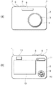
以下、図面を参照して本願の好ましい実施形態について説明する。本実施形態に係るデジタルカメラ1の外観図を図1に示しており、まず、この図面を参照しながらデジタルカメラ1の全体構成について説明する。 Hereinafter, preferred embodiments of the present application will be described with reference to the drawings. An external view of a digital camera 1 according to the present embodiment is shown in FIG. 1. First, the overall configuration of the digital camera 1 will be described with reference to this drawing.
デジタルカメラ1は、略直方体形状をなすカメラ本体2の前面に、レンズ鏡筒4内に設けられた撮像レンズ3や、撮影光量が不足している場合(被写体が暗い場合)に補助光を発光するストロボ発光部5などを備えている。
The digital camera 1 emits auxiliary light on the front surface of the
カメラ本体2の上面には、レリーズボタン6、電源ボタン7、モードダイヤル8などが設けられている。レリーズボタン6は、半押し段階、全押し段階の2段階を検出可能なボタンであり、レリーズボタン6が半押し操作されると、自動露出調節(AE)や自動焦点調節(AF)などの撮影準備動作が行われ、レリーズボタン6が全押し操作されたときに、被写体の画像が記録される。電源ボタン7は、長押し操作されることでデジタルカメラ1の電源をON/OFFに切り換える。
On the upper surface of the
モードダイヤル8は、回転操作によりデジタルカメラ1の動作モードを切り換えるようになっており、表示モード、設定モード、撮影モードの選択等、カメラの機能を変更することができるダイヤルである。デジタルカメラ1は撮影モードとして、ポートレートモード(人撮影モード)、遠景モード、夜景モード、スポーツモードなどを有しており、選択された撮影モードに応じて自動的に撮影条件を調節して、それぞれの撮影シーンに適した撮影を行うことができるようになっている。例えば、ポートレートモードは人物を主要被写体とする撮影モードであり、遠景モードは風景を被写体とする撮影モードである。 The mode dial 8 is configured to switch the operation mode of the digital camera 1 by a rotation operation, and is a dial capable of changing camera functions such as selection of a display mode, a setting mode, and a shooting mode. The digital camera 1 has a portrait mode (personal shooting mode), a distant view mode, a night view mode, a sports mode, etc. as shooting modes, and automatically adjusts shooting conditions according to the selected shooting mode, Shooting suitable for each shooting scene can be performed. For example, the portrait mode is a shooting mode in which a person is a main subject, and the distant view mode is a shooting mode in which a landscape is a subject.
カメラ本体2の背面には、十字キー9、決定ボタン10、ズームボタン11、液晶モニタ12、光学式ファインダ13などが備えられている。十字キー9は、液晶モニタ12上に表示される各種メニューや画像等を選択する際に操作される。決定ボタン10は、十字キー9で選択された項目等を決定する際に操作されるボタンである。ズームボタン11は、撮影時に記録する画像を光学的、電子的に拡大、縮小するために操作されるボタンである。液晶モニタ12は、撮影時に被写体を動画像表示したり、撮影記録した画像や各種メニュー画面などを表示する液晶ディスプレイ(LCD)である。光学式ファインダ13は、被写界を光学的に確認するためのものである。
On the back of the
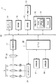
図2は、本実施形態に係るデジタルカメラ1の機能を示すブロック図である。デジタルカメラ1は、図2に示すように、撮像レンズ3、モータドライバ24、撮像素子25、画像処理部27、メモリカードスロットル31、操作部32、表示部33、液晶モニタ12、CPU40、顔検出部41、内部メモリ42、歪補正部44、およびデータバス50などを有している。なお、画像処理部27、メモリカードスロットル31、操作部32、表示部33、CPU40、および内部メモリ42は、データバス50を介して接続されている。また、当然ながらデジタルカメラ1には、他にもカメラの機能を実現するための回路部が備えられているが、その説明については省略する。
FIG. 2 is a block diagram illustrating functions of the digital camera 1 according to the present embodiment. As shown in FIG. 2, the digital camera 1 includes an
撮像レンズ3は、ズームレンズ21、フォーカスレンズ22、絞り23等で構成されており、被写体像を撮像素子25の受光面26上に結像させるための撮影光学系である。ズームレンズ21およびフォーカスレンズ22は、撮像レンズ3の光軸に沿って、広角側または望遠側の方向に移動自在に設けられている。ズームレンズ21は、撮像素子25に結像する光学像を拡大・縮小する(撮像倍率を変化させる)ために、ズームボタン11の押圧操作に応じてモータにて移動されるレンズである。フォーカスレンズ22は、ピントを調節するために、ズームボタン11の押圧操作やズームレンズ21の移動、レリーズボタン6の半押し操作に応じてモータにて移動されるレンズである。絞り23は、レリーズボタン6の半押し操作に応じて絞り開口面積を変化させて、撮像素子25に入射する被写界の光量を調節する。モータドライバ24は、CPU40の指令により各モータを駆動し、ズームレンズ21、フォーカスレンズ22を所定の位置に移動させるとともに、絞り23の開閉状態を制御する。
The
撮像素子25は、撮像レンズ3の背後に設けられており、撮像レンズ3によって受光面26に結像した被写体の光学像を電気信号に光電変換し、アナログの撮像信号を出力するCCDやCMOS等により構成される固体撮像素子である。受光面26は、横方向の長辺および縦方向の短辺を有する長方形状に形成されている。
The
画像処理部27は、撮像素子25から出力されたアナログの電気信号に対して、ノイズの除去やアナログ/デジタル変換してデジタル信号を生成する。また、画像処理部27は、デジタル変換されたデジタル信号に対して補間処理等を施して、液晶モニタ12に表示する表示用画像データや、記録用画像データ等を生成する。メモリカードスロットル31は、デジタルカメラ1に着脱自在に装着されるメモリカード(記憶媒体)内に撮影画像等のデータを書き込んだり、メモリカード内のデータを消去したりするためのスロットルである。
The
操作部32は、レリーズボタン6、電源ボタン7、モードダイヤル8、十字キー9、決定ボタン10、ズームボタン11などを有しており、レリーズボタン6の半押し操作、全押し操作等を検出する。表示部33は、CPU40の指令により画面データを生成し、デジタルカメラ1の背面側に設けられた液晶モニタ12にこの画像データを表示させる。
The
CPU40は、デジタルカメラ1で実行される種々の機能を実現するための制御プログラムを処理する回路である。CPU40は、CPU内メモリ、内部メモリ42に記憶された制御用プログラム読み出し、これを実行することで、デジタルカメラ1内の各部を統括的に制御する。
The
顔検出部41は、撮像素子25で撮像した画像データに対して、人物の特徴量を解析する人物抽出を行って、被写体の顔エリア等を検出する。顔検出部41は、例えば、人物の瞳(眼)抽出や、顔の輪郭抽出を実施することにより、撮影画像における人物の顔の大きさおよび位置を特定する。顔検出部41によって画像データに対して顔が認識されると、CPU40により撮像レンズ3の焦点を顔エリアに合わせる焦点調節制御や、顔エリアの露出を適正露出にする露出制御などが行われる。
The
内部メモリ42は、例えば、CPU40に各種処理を実行させるための制御用プログラム(ファームウェア)等を格納したROMや、撮像素子25により撮像された画像データ等の各種データを記憶するRAMなどから構成されている。内部メモリ42は、被写体の顔エリアを検出するために実行される顔検出プログラムを記憶しており、また、顔認識処理により得られた顔位置、顔の大きさ等の被写体の顔情報を記憶することができる。さらに、内部メモリ42のROMには、撮像された画像に対する歪曲の補正に用いられる歪補正テーブル43が格納されている。
The
歪補正テーブル43には、後述の歪補正部44によって、撮影した画像のディストーション補正をするときに読み出される歪曲補正関数の係数等が格納されている。
The distortion correction table 43 stores, for example, a coefficient of a distortion correction function that is read when distortion correction of a captured image is performed by a
歪補正部44は、撮像レンズ3の歪曲収差によって生じるディストーションを補正するため、撮影した画像データに対して所定の歪曲補正関数を用いて画像変換処理を行う。例えば、歪曲補正関数dis(r)は多項式として、
dis(r)=A0+A1×r+A2×r2+A3×r3+・・・+An×rn …(1)
で表すことができる。なお、rは画像変換処理前における画像の中心からの像高であり、An(A0,A1,A2,A3・・・)は各次数項での多項式係数(歪曲収差係数)であって歪補正テーブル43に格納されている。なお、これに限定されるものではなく、撮像レンズ3の歪曲収差データを撮像された画像の位置(画素位置)ごとにデータテーブル化して歪補正テーブル43に格納し、これを歪補正部44によって読み出して、撮影した画像データに対して画像変換処理(ディストーション補正)を行うように構成してもよい。
The
dis (r) = A 0 + A 1 × r + A 2 × r 2 + A 3 × r 3 +... + A n × r n (1)
It can be expressed as Note that r is the image height from the center of the image before the image conversion process, and An (A 0 , A 1 , A 2 , A 3 ...) Is a polynomial coefficient (distortion aberration coefficient) in each order term. And stored in the distortion correction table 43. However, the present invention is not limited to this, and the distortion aberration data of the
ところで、このように構成されるデジタルカメラ1において、通常、撮像レンズ3の射影方式は、撮像素子25の受光面26上での像高をr、撮像レンズ3の焦点距離をf、被写体からの入射角(半画角)をθとすると、
r=f×tanθ …(2)
に従う射影方式が用いられている。
By the way, in the digital camera 1 configured as described above, normally, the projection method of the
r = f × tan θ (2)
A projection method according to is used.
このとき一般に、式(2)に従う射影方式により撮像された画像には、画像フレームの中心付近と周辺部とでの結像倍率の違いによる撮像レンズ3の歪曲収差によって、いわゆる糸巻型もしくは樽型のディストーションが生じる(特に、レンズの広角端では樽型のディストーションが発生し易い)。このようなディストーションを補正するには、前述したように歪補正部44により、撮影した画像データに対して式(1)に示す上述の歪曲補正関数dis(r)を用いて画像変換処理を行うことで、ディストーションが低減された画像を得ることできる。
At this time, generally, an image picked up by the projection method according to Expression (2) includes a so-called pincushion type or barrel type depending on the distortion aberration of the
しかしながら、これは平面的な被写体が歪みなく撮影できるというものであって、このようなディストーションとは別に立体的な被写体を考えた場合、画像フレーム周辺の被写体の像が引き伸ばされたような歪み(これは一般に、「パースペクティブディストーション」、もしくは「広角歪」と称されており、以下の説明では「広角歪」と称する)が生じるという問題を有している。 However, this means that a planar subject can be photographed without distortion, and when considering a three-dimensional subject apart from such distortion, the distortion (such as a stretched image of the subject around the image frame) This is generally referred to as “perspective distortion” or “wide-angle distortion” and is referred to as “wide-angle distortion” in the following description).
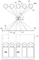
ここで、図3は画面周辺に写り込んだ被写体像の広角歪を説明するための模式図であり、この図を用いて広角歪が生じる様子を説明する。立体的な被写体として人物を想定した場合、人物の頭部は概ね球形状、胴体部は概ね円筒形状と考えることができ、図3に示すように、人物をデジタルカメラ1の正面側でほぼ横一列に整列させて撮影を行うと、周辺に写った人物は入射角をθとして、1/cosθだけ横に引き伸ばされて写ってしまう。 Here, FIG. 3 is a schematic diagram for explaining the wide-angle distortion of the subject image reflected in the periphery of the screen, and the manner in which the wide-angle distortion occurs will be described using this figure. When a person is assumed as a three-dimensional object, the person's head can be considered to be approximately spherical and the body is approximately cylindrical. As shown in FIG. When taking a picture in a line, a person in the vicinity is taken to be horizontally stretched by 1 / cos θ with an incident angle θ.
これは、撮像レンズ3のほぼ正面に位置する人物60aに対しては、この人物(球体もしくは円筒体で想定したもの)60aの直径となる線分P1P2および撮像レンズ中心P0により形成される三角形P0P1P2と、受光面26上に結像された線分P1P2の像P1′P2′および撮像レンズ中心P0により形成される三角形P0P1′P2′は相似形であるため、この人物60aの像は受光面26上に理想的な像として結像される。一方、周辺に位置する人物60bに対しては、この人物(球体もしくは円筒体で想定したもの)60bの直径となる線分P3P4および撮像レンズP0により形成される三角形P0P3P4と、受光面26上に結像された線分P3P4の像P3′P5および撮像レンズ中心P0により形成される三角形P0P3′P5′とは相似形とはならず、線分P3P4は、理想的に縮尺された線分P3′P4′よりも引き伸ばされた線分P3′P5′となって受光面26上に結像される。これが、図3に示すように、画面周辺に位置する人物の像が横に引き伸ばされて太って写ってしまう原因である。
For a
このため、このような立体的な被写体像に対して広角歪を低減するためには、立体的(球状)な被写体に対して撮像素子25の受光面26上に結像される水平方向(横方向)と垂直方向(縦方向)の像の大きさが一致するような射影方式を選択すればよいことになる。そこで、本実施形態のデジタルカメラ1では、歪補正部44が、歪曲収差によるディストーション補正の他に、撮像素子25により撮像された画像データに対して次述の他の射影方式の画像に変換する画像変換処理を行うように構成されている。
For this reason, in order to reduce wide-angle distortion for such a three-dimensional subject image, a horizontal (horizontal) image formed on the
図4は、歪補正部44によって画像変換処理を行うために本実施形態に適用される射影方式を説明するための模式図である。ここで、被写体(物界)を点Pを中心とした球61として表し、被写体像(像界)をこの球と接する平面62で表し、球61の中心Pと平面62(上の接点)との距離(すなわち球61の半径)を焦点距離fとして表したとき、式(2)に示す通常のレンズの射影方式(r=f・tanθ)は、点Pから平面62に至る直線L1で表すことができる。なお、図4においては、図示のようにXYZ直交座標系を設定しており、Y軸が紙面に対して直行する方向に設定され、X軸がY軸とともに平面に平行になるように設定され、Z軸が平面に対して直交する方向に設定されている。
FIG. 4 is a schematic diagram for explaining a projection method applied to the present embodiment in order to perform image conversion processing by the
一方、画像変換のための本射影方式は、任意の変数uを用いて、点PからZ軸に沿って距離f・uだけ離れた点Sから平面62(XY平面)に至る直線L2で表すことができ、この直線L2と平面62との交点の高さxが像界における被写体の像高となる。すなわち、Z軸と直線L2との角度をδとして、この射影方式を式化すると、
x=f(u+1)×tanδ …(3)
で表わされる。このとき、図4から、
tanδ=sinθ/(u+cosθ) …(4)
であることから、これを式(3)に代入してδを消去すると、結局xは、
x=f(u+1)・sinθ/(u+cosθ) …(5)
と表すことができる。
On the other hand, this projection method for image conversion uses an arbitrary variable u and is represented by a straight line L2 extending from the point S from the point P by the distance f · u along the Z axis to the plane 62 (XY plane). The height x of the intersection between the straight line L2 and the plane 62 becomes the image height of the subject in the image field. That is, when this projection method is formulated with the angle between the Z axis and the straight line L2 as δ,
x = f (u + 1) × tan δ (3)
It is represented by At this time, from FIG.
tan δ = sin θ / (u + cos θ) (4)
Therefore, if this is substituted into equation (3) and δ is eliminated, x will eventually become
x = f (u + 1) · sin θ / (u + cos θ) (5)
It can be expressed as.
ここで、式(5)において、u=0のときはx=f・tanθとなり通常の射影方式、u=1のときはx=2f・sin(θ/2)となり立体射影方式、u=∞のときはx=f・sinθとなり正射影方式を表すこととなる。このため、uの値を適切に選択して最適な射影方式を導くことによって像高xを調節して、広角歪の低減された画像を得ることが可能になる。なお、以降の説明では、uを射影方式の変換係数と称する。 Here, in equation (5), when u = 0, x = f · tan θ and normal projection method, and when u = 1, x = 2f · sin (θ / 2) and stereoscopic projection method, u = ∞ In this case, x = f · sin θ, which represents an orthogonal projection method. For this reason, it is possible to obtain an image with reduced wide-angle distortion by appropriately selecting the value of u and deriving an optimum projection method to adjust the image height x. In the following description, u is referred to as a projection conversion factor.
このとき、歪みのない画像を得る条件は、物界上で直径aの微小な円盤状に表される物体63の像を考えたとき、像界上でのこの像のX軸方向の大きさΔxとY軸方向の大きさΔyとが等しいこと、すなわち、
Δx=Δy …(6)
となることである。このときΔxは、一般に次式(7)で表すことができる。
Δx=a・f(u+1)(cos(θ−δ))
/((u+cosθ)・cosδ) …(7)
また、この式(7)において、三角関数の基本式を利用してδを消去するように変形すると、Δxは、
Δx=a・f(u+1)(u・cosθ+1)/(u+cosθ)2 …(8)
と変形することができる。
At this time, the condition for obtaining an image without distortion is that the size of this image on the image field in the X-axis direction is considered when an image of the
Δx = Δy (6)
It is to become. At this time, Δx can be generally expressed by the following equation (7).
Δx = a · f (u + 1) (cos (θ−δ))
/ ((U + cosθ) · cosδ) (7)
In addition, in this equation (7), if the basic equation of the trigonometric function is used to eliminate δ, Δx becomes
Δx = a · f (u + 1) (u · cos θ + 1) / (u + cos θ) 2 (8)
And can be transformed.
一方、物体63のY軸方向の像の大きさΔyについては、X軸(Y=0)近傍においては平面被写体の水平線(横線)が歪まないという条件から、次式(9)のように表すことができる。
Δy=a・f/cosθ …(9)
On the other hand, the image size Δy of the
Δy = a · f / cos θ (9)
したがって、上記の条件式(6)であるΔx=Δyに、式(8)および式(9)を代入することで、次式(10)を得ることができる。
a・f(u+1)(u・cosθ+1)/(u+cosθ)2
=a・f/cosθ …(10)
また、過程は省略するが、この式(10)を変形すると、式(10)は次式(11)のように簡素化される。
(cosθ+1)・u2+(cosθ)・u−cosθ=0 ・・・(11)
Therefore, the following equation (10) can be obtained by substituting the equations (8) and (9) into Δx = Δy, which is the conditional equation (6).
a · f (u + 1) (u · cos θ + 1) / (u + cos θ) 2
= A · f / cos θ (10)
Further, although the process is omitted, when the equation (10) is modified, the equation (10) is simplified as the following equation (11).
(Cos θ + 1) · u 2 + (cos θ) · u−cos θ = 0 (11)
方程式(10)からuについて解を導くと、
u=(−cosθ+(5cosθ2+4cosθ)1/2)
/(2(cosθ+1)) …(12)
となり、入射角θのみに依存する関数となることがわかる。
Deriving the solution for u from equation (10),
u = (− cos θ + (5 cos θ 2 +4 cos θ) 1/2 )
/ (2 (cos θ + 1)) (12)
Thus, it can be seen that the function depends only on the incident angle θ.
このとき式(12)において、θ=0°のときはu=0.5、0°<θ≦45°のときはu=0.46となり、上記条件の下ではこのu値が広角歪補正のための良好な値であることがわかる。なお、θが45°よりも大きい範囲ではuは0.46よりも小さな値となる。また、上述では説明の便宜のため、X軸近傍の画像における歪みを低減する条件を前提として説明したが、当然ながらX軸から離れた位置の画像に対してもuを適切に選択して広角歪を低減することが可能である。 In this case, in equation (12), when θ = 0 °, u = 0.5, and when 0 ° <θ ≦ 45 °, u = 0.46. Under the above conditions, this u value is a wide-angle distortion correction. It can be seen that this is a good value for. Note that u is a value smaller than 0.46 in the range where θ is larger than 45 °. Further, in the above description, for convenience of explanation, the description has been made on the assumption that the distortion in the image near the X axis is reduced. However, naturally, u is appropriately selected for an image at a position away from the X axis, and a wide angle It is possible to reduce distortion.
以上のように、本実施形態においてuはθに依存する関数であり、広角歪の低減された均一な画像を得るため、像高xを表す式(5)に対してuが次式(13)の条件を満足することが好ましい。 As described above, in the present embodiment, u is a function dependent on θ, and in order to obtain a uniform image with reduced wide-angle distortion, u is expressed by the following equation (13) with respect to equation (5) representing the image height x. It is preferable to satisfy the condition of
0.3<u<0.7 …(13) 0.3 <u <0.7 (13)
ここで、uが条件式(13)を満足するとき、式(5)において像高xは、
f・θ<x<f・tanθ …(14)
を満足し、uが条件式(13)内で適切に選択された本射影方式が、等角射影方式(x=f・θ)と、通常のレンズの射影方式(x=f・tanθ)との間の射影方式であることがわかる。
Here, when u satisfies the conditional expression (13), the image height x in the expression (5) is
f · θ <x <f · tan θ (14)
And the projection method in which u is appropriately selected in the conditional expression (13) is a conformal projection method (x = f · θ) and a normal lens projection method (x = f · tan θ). It can be seen that the projection method is between.
なお、本実施形態の効果を確実にするために、条件式(13)の上限値を0.65にすることが好ましい。また、本実施形態の効果を確実にするために、条件式(13)の下限値を0.35にすることが好ましい。 In order to secure the effect of the present embodiment, it is preferable to set the upper limit of conditional expression (13) to 0.65. In order to secure the effect of the present embodiment, it is preferable to set the lower limit of conditional expression (13) to 0.35.
このように歪補正部44は、式(2)に示す射影方式により撮像された画像に対して、式(5)および(13)を満足するような射影方式の画像に変換する画像変換処理を実施するようになっており、適切に歪曲が低減された画像を簡単に得ることが可能になる。
Thus, the
また、本実施形態においては、撮影条件が、(a)モードダイヤル8により選択される撮影モードが人物を被写体として想定したポートレートモードのとき、(b)顔検出部41により撮像素子25で撮像された画像中に人物の顔が認識されたとき、(c)顔検出部41により画像の周辺部に人物の顔が認識されたとき、等に合致した場合に歪補正部44により画像変換処理を施すようにすることが好ましい。これは撮影される主要な被写体が人物である場合に撮影した画像に対して広角歪を補正することで、上述したような(特に画面周辺の)人物の像が引き伸ばされるという不具合を防止する効果を確実にするためである。
In the present embodiment, when the shooting condition is (a) the portrait mode in which the shooting mode selected by the mode dial 8 is assumed to be a person as a subject, (b) the
次に、以上のように構成される本実施形態に係るデジタルカメラ1の動作の一例について、図5および図6を追加参照して説明する。図5はデジタルカメラ1の撮影動作を示すフローチャート、図6は撮像素子25の受光面26(画像フレーム)の座標系を説明するための模式図である。
Next, an example of the operation of the digital camera 1 according to this embodiment configured as described above will be described with additional reference to FIGS. 5 and 6. FIG. 5 is a flowchart showing the photographing operation of the digital camera 1, and FIG. 6 is a schematic diagram for explaining the coordinate system of the light receiving surface 26 (image frame) of the
まず、撮影者が電源ボタン7を操作することによりデジタルカメラ1の電源がONとなり、動作モードが撮影モードに設定されると、CPU40は画像処理部27や表示部33などを制御して、液晶モニタ12に被写体の動画像をスルー画として表示させる。撮影者は液晶モニタ12に表示される動画像を確認し撮影構図を決定する。
First, when the photographer operates the
液晶モニタ12にスルー画が表示されているときに、撮影者がレリーズボタン6を半押し操作して撮影準備を指示すると(ステップS101)、顔検出部41は画像処理部27から入力した画像に基づいて顔認識処理を実行する(ステップS102)。続いて撮影者がレリーズボタン6を全押し操作して撮影を指示すると、CPU40は撮影画像が適正露出となるように露光動作等の撮影処理を行う(ステップS103)。
When the photographer operates the
そして、ステップS104においては、撮影前にモードダイヤル8により選択された撮影モードがポートレートモードであるか否かを判定し、ポートレートモードが選択されている場合には肯定判定されてステップS106に進む。一方、他の撮影モードが選択され否定判定されると、ステップS105に進んで、ステップS102における顔認識処理の結果、撮像された画像内に人物の顔が認識されたか否かを判定する。ここで、判定対象となる顔が認識された場合とは、位置を問わず画像フレーム内のいずれかで顔が認識された場合を意味するが、これに限定されるものではなく、画像フレーム周辺部でのみ顔が認識された場合としてもよい。ステップS102で顔認識がされ人物の顔が検出されている場合にはステップS105において肯定判定されて、ステップS106に進む。 In step S104, it is determined whether or not the shooting mode selected by the mode dial 8 before shooting is the portrait mode. If the portrait mode is selected, an affirmative determination is made and the process proceeds to step S106. move on. On the other hand, if another shooting mode is selected and a negative determination is made, the process proceeds to step S105, where it is determined whether or not a person's face is recognized in the captured image as a result of the face recognition process in step S102. Here, the case where the face to be determined is recognized means the case where the face is recognized anywhere in the image frame regardless of the position, but the present invention is not limited to this. The face may be recognized only at the part. If the face is recognized in step S102 and a human face is detected, an affirmative determination is made in step S105, and the process proceeds to step S106.
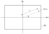
ステップS106において、CPU40は撮像素子25から画像(撮像信号)を取得して画像処理部27に入力して、画像処理部27で前述した画像処理の施された画像データを取得する。次いで、歪補正部44は、撮像素子25の受光面26上の座標系を、受光面中心を基準としてX軸(撮像素子25の長辺(横)方向の軸)とY軸(撮像素子25の短辺(縦)方向の軸)とで表される直交座標系から極座標系に変換する座標変換処理を行う(ステップS107)。この座標変換処理では、受光面26上の任意の点(画素)Qの座標(x,y)を、次式(15)、(16)で表される極座標(r,α)に変換する。
r=(x2+y2)1/2 ・・・(15)
α=atan(y/x) ・・・(16)
In step S <b> 106, the
r = (x 2 + y 2 ) 1/2 (15)
α = atan (y / x) (16)
そして、歪補正部44は、この極座標(r,α)に座標変換された画像データに対して、撮像レンズ3の歪曲収差に基づくディストーション補正を行う(ステップS108)。ディストーション補正後の極座標(r′,α′)の各値は、上述した式(1)の歪曲補正関数dis(r)を利用して、
r′=r/(1+dist(r)) …(17)
α′=α …(18)
で表すことができる。なお、このディストーション補正では、基準軸X,Yとのなす角度α′は変化せず、補正後の像高r′の大きさのみが修正される。
Then, the
r '= r / (1 + dist (r)) (17)
α ′ = α (18)
It can be expressed as In this distortion correction, the angle α ′ formed with the reference axes X and Y does not change, and only the corrected image height r ′ is corrected.
次いで、この極座標(r′,α′)を再び受光面26に対応したXY座標系の座標(x′,y′)に再変換する(戻す)処理が行われる(ステップS109)。
x′=r′cosα′ …(19)
y′=r′sinα′ …(20)
ここまでが一般のディストーション補正の流れであり、ここからが本実施形態による広角歪補正の流れになる。なお、ここでは説明の便宜上、画像におけるX軸方向(長辺方向)の広角歪補正処理を一例として説明する。
Next, a process of reconverting (returning) the polar coordinates (r ′, α ′) to the coordinates (x ′, y ′) of the XY coordinate system corresponding to the
x ′ = r′cos α ′ (19)
y ′ = r′sin α ′ (20)
The flow up to here is a general distortion correction flow, and the flow from here is the flow of wide-angle distortion correction according to the present embodiment. Here, for convenience of explanation, a wide-angle distortion correction process in the X-axis direction (long-side direction) of an image will be described as an example.
まず、X軸方向に沿った画像中心からの距離(像高)x′に対して撮像レンズ3の焦点距離をfとすると、被写体からの入射角θXは、
θX=atan(x/f) …(21)
で表すことができる(ステップS110)。ここで、画像中心からの距離x′については射影方式の変換係数uを用いて上述した条件式(5)に適用すると(ステップS111)、式(5)による射影方式の画像に変換処理した後の座標(x″,y″)は、次式(5)′および(22)で表される(ステップS112)。
x″=f(u+1)・sinθX/(u+cosθX) …(5)′
y″=y′ …(22)
このとき、式(5)′で表される射影方式の変換係数uを上述した条件式(13)の範囲内で適切に選択することで、X軸方向(横方向)に圧縮され広角歪が適切に補正された画像を得ることが可能になる。
First, when the focal length of the
θ X = atan (x / f) (21)
(Step S110). Here, if the distance x ′ from the image center is applied to the conditional expression (5) using the conversion coefficient u of the projection method (step S111), the image is converted into a projection method image according to the expression (5). The coordinates (x ″, y ″) are expressed by the following equations (5) ′ and (22) (step S112).
x ″ = f (u + 1) · sin θ X / (u + cos θ X ) (5) ′
y ″ = y ′ (22)
At this time, by appropriately selecting the conversion coefficient u of the projection method represented by Expression (5) ′ within the range of Conditional Expression (13) described above, it is compressed in the X-axis direction (lateral direction) and wide-angle distortion is generated. An appropriately corrected image can be obtained.
一方、画像上で顔が検出されずステップS105で否定判定されると(すなわち、ステップS104およびS105において共に否定判定されると)、ステップS106′に進むこととなる。ここで、ステップS106′〜ステップS109′については、一般のディストーション補正の流れである前述したステップS106〜ステップS109での処理と同様であるので、その重複説明は省略する。 On the other hand, if a face is not detected on the image and a negative determination is made in step S105 (that is, a negative determination is made in both steps S104 and S105), the process proceeds to step S106 ′. Here, Steps S106 ′ to S109 ′ are the same as the processing in Steps S106 to S109 described above, which is a general flow of distortion correction, and thus redundant description thereof is omitted.
そして、CPU40は画像変換処理された画像データを圧縮処理して、内部メモリ42(RAM)に記録する(ステップS113)。なお、CPU40は撮影により取得されたこの画像を液晶モニタ12に一定時間だけ表示させる。これによりデジタルカメラ1における一連の撮影動作が終了する。
Then, the
以上、本実施形態のデジタルカメラ1によれば、取得画像を式(5)等に示す射影方式の画像に変換する処理を行うことで広角歪を適切に補正することにより、水平および垂直方向の直線の歪みがなく、且つ、画面周辺の人物の歪みが低減された均一な画像を得ることができる。 As described above, according to the digital camera 1 of the present embodiment, the horizontal and vertical directions can be corrected by appropriately correcting the wide-angle distortion by performing the process of converting the acquired image into the image of the projection method shown in Expression (5). A uniform image with no straight line distortion and reduced distortion of the person around the screen can be obtained.
なお、本実施形態のデジタルカメラ1では、水平および垂直線の歪みが改善されるものの、斜めに延びる線に対しては多少歪みが発生するおそれがあり、また、壁のタイル等の規則的な尺目を撮影したときには画面周辺での尺目がやや縦長になるおそれが考えられる。このため、本デジタルカメラ1は、主要な被写体を人物として撮影する場合に最も適している。 In the digital camera 1 of the present embodiment, although the distortion of horizontal and vertical lines is improved, there is a possibility that a slight distortion may occur with respect to an obliquely extending line, and a regular pattern such as a wall tile is used. There is a possibility that when the measure is photographed, the measure around the screen is slightly vertically long. For this reason, the digital camera 1 is most suitable for photographing a main subject as a person.
また、上述の実施例においては、撮像された画像に対してX軸方向(長辺方向)のみの広角歪の補正処理について説明したが、これに限定されるものではなく、Y軸方向(短辺方向)にも条件式(5)および(13)を適用して、Y軸方向、もしくはX,Y軸両方向に対する広角歪の補正を行ってもよい。 In the above-described embodiments, the wide-angle distortion correction processing only in the X-axis direction (long-side direction) has been described for the captured image. However, the present invention is not limited to this, and the Y-axis direction (short Conditional expressions (5) and (13) may also be applied to the side direction to correct wide-angle distortion in the Y-axis direction or both the X and Y-axis directions.
さらに、上述の実施形態においては、撮影モードがポートレートモードに選択されているときや、画像中に顔認識されたときに限って、歪補正部44が広角歪補正のための画像変換処理を実行しているが、これに限定されるものではなく、他の撮影モード(例えば、夜景ポートレートモード)が選択された場合に画像変換処理を行うように構成してもよい。
Furthermore, in the above-described embodiment, the
また、上述の実施形態においては、図2において説明の便宜上、顔検出部41および歪補正部44という機能ブロックを設けているが、本実施形態では所定の制御用プログラムに基づいてCPUが各機能を実現するようになっている。
In the above-described embodiment, for convenience of explanation in FIG. 2, functional blocks such as a
さらに、通常の射影方式により撮像された画像に対して、前述したような所定の射影方式の画像に変換する画像変換処理は、デジタルカメラ1(の歪補正部)による処理に限定されるものではなく、カメラにより撮影取得した画像に対して、例えばCPUを有するコンピュータ(画像処理装置など)により行ってもよく、当然ながら同様の効果を得ることができる。 Furthermore, the image conversion processing for converting an image captured by the normal projection method into an image of the predetermined projection method as described above is not limited to the processing by the digital camera 1 (distortion correction unit thereof). Alternatively, for example, a computer (image processing apparatus or the like) having a CPU may be used for an image photographed and acquired by the camera, and the same effect can be obtained naturally.
1 デジタルカメラ(カメラ)
3 撮像レンズ(撮影光学系)
8 モードダイヤル
25 撮像素子
26 受光面
40 CPU(処理部)
41 顔検出部
44 歪補正部(処理部)
1 Digital camera (camera)
3 Imaging lens (photographing optical system)
8
41
Claims (8)
前記撮影光学系の焦点距離と、前記撮影光学系への被写体からの光線の入射角とに基づいて、前記画像の歪曲を補正する際に、前記入射角に応じて歪曲補正量を変更する処理部を備え、
前記処理部は、前記歪曲補正量を変更するための補正パターンを有し、
前記補正パターンは、前記被写体から前記撮影光学系への入射角をθとし、前記撮影光学系の焦点距離をfとし、前記画像の中心から、前記画像の中心を通って互いに直交する画像の長辺方向および短辺方向のうちの少なくとも1方向に沿った像高をxとし、射影方式の変換係数をuとしたとき、式
x=f(u+1)・sinθ/(u+cosθ)
0.3<u<0.7
の条件を満足する射影方式に従って前記歪曲補正量を変更することを特徴とするカメラ。 In a camera that forms an image with a taking optical system,
Processing for changing the distortion correction amount according to the incident angle when correcting the distortion of the image based on the focal length of the photographing optical system and the incident angle of the light beam from the subject to the photographing optical system with a part,
The processing unit has a correction pattern for changing the distortion correction amount,
The correction pattern has an incident angle from the subject to the photographing optical system as θ, a focal length of the photographing optical system as f, and lengths of images orthogonal to each other from the center of the image through the center of the image. When the image height along at least one of the side direction and the short side direction is x and the conversion coefficient of the projection method is u, the equation
x = f (u + 1) · sin θ / (u + cos θ)
0.3 <u <0.7
The distortion correction amount is changed according to a projection method that satisfies the above condition .
y=f・tanθ
の条件を満足する射影方式に従って前記歪曲補正量を変更するもう一つの補正パターンを有することを特徴とする請求項1に記載のカメラ。 The processing unit further has an equation where y is the image height of the image by the imaging optical system.
y = f · tan θ
The camera according to claim 1 , further comprising another correction pattern for changing the distortion correction amount according to a projection method that satisfies the above condition .
前記撮影光学系の焦点距離と前記撮影光学系への被写体からの光線の入射角とに基づいて、前記画像の歪曲を補正する際に、前記入射角に応じて歪曲補正量を変更する補正量変更ステップとを有し、
前記補正量変更ステップは、前記被写体から前記撮影光学系への入射角をθとし、前記撮影光学系の焦点距離をfとし、前記画像の中心から、前記画像の中心を通って互いに直交する画像の長辺方向および短辺方向のうちの少なくとも1方向に沿った像高をxとし、射影方式の変換係数をuとしたとき、式
x=f(u+1)・sinθ/(u+cosθ)
0.3<u<0.7
の条件を満足する射影方式に従って前記歪曲補正量を変更することを特徴とする画像補正方法。 An image acquisition step of forming an image by a photographing optical system;
A correction amount for changing the distortion correction amount according to the incident angle when correcting the distortion of the image based on the focal length of the photographing optical system and the incident angle of the light beam from the subject to the photographing optical system. A modification step,
In the correction amount changing step, an incident angle from the subject to the photographing optical system is θ, a focal length of the photographing optical system is f, and images orthogonal to each other from the center of the image through the center of the image. Where x is the image height along at least one of the long side direction and the short side direction, and u is the conversion coefficient of the projection method.
x = f (u + 1) · sin θ / (u + cos θ)
0.3 <u <0.7
An image correction method, wherein the distortion correction amount is changed according to a projection method that satisfies the above condition .
Priority Applications (4)
| Application Number | Priority Date | Filing Date | Title |
|---|---|---|---|
| JP2009067811A JP5397751B2 (en) | 2009-03-19 | 2009-03-19 | Camera and image correction method |
| EP10156802.0A EP2230833B1 (en) | 2009-03-19 | 2010-03-17 | Camera having image correction function, apparatus and image correction method |
| US12/726,699 US8466989B2 (en) | 2009-03-19 | 2010-03-18 | Camera having image correction function, apparatus and image correction method |
| CN201010143284.1A CN101841657B (en) | 2009-03-19 | 2010-03-18 | Camera having image correction function, apparatus and image correction method |
Applications Claiming Priority (1)
| Application Number | Priority Date | Filing Date | Title |
|---|---|---|---|
| JP2009067811A JP5397751B2 (en) | 2009-03-19 | 2009-03-19 | Camera and image correction method |
Publications (2)
| Publication Number | Publication Date |
|---|---|
| JP2010226157A JP2010226157A (en) | 2010-10-07 |
| JP5397751B2 true JP5397751B2 (en) | 2014-01-22 |
Family
ID=42235719
Family Applications (1)
| Application Number | Title | Priority Date | Filing Date |
|---|---|---|---|
| JP2009067811A Expired - Fee Related JP5397751B2 (en) | 2009-03-19 | 2009-03-19 | Camera and image correction method |
Country Status (4)
| Country | Link |
|---|---|
| US (1) | US8466989B2 (en) |
| EP (1) | EP2230833B1 (en) |
| JP (1) | JP5397751B2 (en) |
| CN (1) | CN101841657B (en) |
Families Citing this family (23)
| Publication number | Priority date | Publication date | Assignee | Title |
|---|---|---|---|---|
| JP4912238B2 (en) * | 2007-07-09 | 2012-04-11 | キヤノン株式会社 | Imaging device and interchangeable lens device |
| JP5590498B2 (en) * | 2009-09-07 | 2014-09-17 | 株式会社ニコン | Projection device |
| KR101599885B1 (en) * | 2009-09-29 | 2016-03-04 | 삼성전자주식회사 | Digital photographing apparatus and photographing method |
| JP5550325B2 (en) * | 2009-12-18 | 2014-07-16 | キヤノン株式会社 | Image processing apparatus and image processing method |
| JP5544277B2 (en) * | 2010-10-29 | 2014-07-09 | 株式会社日立情報通信エンジニアリング | Image correction apparatus, correction image generation method, correction table generation apparatus, correction table generation method, correction table generation program, and correction image generation program |
| CN102638674A (en) * | 2012-01-18 | 2012-08-15 | 宁波捷宏信息技术有限公司 | Omnidirectional visual detecting, analyzing and warning system on basis of fisheye correction technology |
| JP2013219544A (en) * | 2012-04-09 | 2013-10-24 | Ricoh Co Ltd | Image processing apparatus, image processing method, and image processing program |
| JP5893746B2 (en) * | 2013-01-24 | 2016-03-23 | Cbc株式会社 | CCTV lens and correction method of CCTV lens |
| JP5971216B2 (en) * | 2013-09-20 | 2016-08-17 | カシオ計算機株式会社 | Image processing apparatus, image processing method, and program |
| JP2015095857A (en) * | 2013-11-14 | 2015-05-18 | キヤノン株式会社 | Imaging apparatus |
| US9330436B2 (en) * | 2014-04-01 | 2016-05-03 | Gopro, Inc. | Multi-camera array with adjacent fields of view |
| JP5983717B2 (en) * | 2014-12-17 | 2016-09-06 | 辰巳電子工業株式会社 | Imaging apparatus, imaging method, and program thereof |
| JP6504825B2 (en) * | 2015-01-15 | 2019-04-24 | キヤノン株式会社 | Imaging device, control method therefor, program, storage medium |
| US9514524B2 (en) * | 2015-02-27 | 2016-12-06 | Sony Corporation | Optical distortion compensation |
| KR102290301B1 (en) * | 2015-05-06 | 2021-08-17 | 엘지전자 주식회사 | Mobile terminal and method of controlling the same |
| CN107004261B (en) * | 2015-09-15 | 2020-01-21 | 华为技术有限公司 | Image distortion correction method and device |
| US11602265B2 (en) | 2016-03-31 | 2023-03-14 | Sony Corporation | Control device, endoscopic imaging device, control method, program, and endoscopic system |
| JP6875836B2 (en) * | 2016-11-29 | 2021-05-26 | 株式会社明電舎 | Wire rope measuring device and method |
| US10643177B2 (en) * | 2017-03-21 | 2020-05-05 | Kellogg Company | Determining product placement compliance |
| TWI692741B (en) * | 2018-01-18 | 2020-05-01 | 鈺立微電子股份有限公司 | System of camera calibration |
| JP7031489B2 (en) * | 2018-05-15 | 2022-03-08 | 富士通株式会社 | Compensation program, compensation method and compensation device |
| CN108765537A (en) * | 2018-06-04 | 2018-11-06 | 北京旷视科技有限公司 | A kind of processing method of image, device, electronic equipment and computer-readable medium |
| CN110072045B (en) * | 2019-05-30 | 2021-11-09 | Oppo广东移动通信有限公司 | Lens, camera and electronic equipment |
Family Cites Families (7)
| Publication number | Priority date | Publication date | Assignee | Title |
|---|---|---|---|---|
| JP2000011166A (en) * | 1998-06-24 | 2000-01-14 | Sony Corp | Image processing apparatus and method, and providing medium |
| JP2005110202A (en) * | 2003-09-08 | 2005-04-21 | Auto Network Gijutsu Kenkyusho:Kk | Camera device and vehicle periphery monitoring device |
| JP4766841B2 (en) * | 2003-09-08 | 2011-09-07 | 株式会社オートネットワーク技術研究所 | Camera device and vehicle periphery monitoring device mounted on vehicle |
| JP2006025340A (en) | 2004-07-09 | 2006-01-26 | Canon Inc | Wide-angle imaging device, imaging system, and control method thereof |
| WO2007129446A1 (en) | 2006-05-01 | 2007-11-15 | Nikon Corporation | Image processing method, image processing program, image processing device, and imaging device |
| JP4914171B2 (en) | 2006-10-16 | 2012-04-11 | キヤノン株式会社 | Imaging device control method and camera system |
| JP4714174B2 (en) * | 2007-03-27 | 2011-06-29 | 富士フイルム株式会社 | Imaging device |
-
2009
- 2009-03-19 JP JP2009067811A patent/JP5397751B2/en not_active Expired - Fee Related
-
2010
- 2010-03-17 EP EP10156802.0A patent/EP2230833B1/en not_active Not-in-force
- 2010-03-18 CN CN201010143284.1A patent/CN101841657B/en not_active Expired - Fee Related
- 2010-03-18 US US12/726,699 patent/US8466989B2/en active Active
Also Published As
| Publication number | Publication date |
|---|---|
| EP2230833A1 (en) | 2010-09-22 |
| CN101841657B (en) | 2015-04-29 |
| CN101841657A (en) | 2010-09-22 |
| EP2230833B1 (en) | 2013-08-21 |
| JP2010226157A (en) | 2010-10-07 |
| US8466989B2 (en) | 2013-06-18 |
| US20100265365A1 (en) | 2010-10-21 |
Similar Documents
| Publication | Publication Date | Title |
|---|---|---|
| JP5397751B2 (en) | Camera and image correction method | |
| US8023009B2 (en) | Imaging apparatus for correcting optical distortion and wide-angle distortion | |
| US8212895B2 (en) | Digital camera system with portrait effect | |
| CN103024265B (en) | The image capture method of camera head and camera head | |
| JP5106142B2 (en) | Electronic camera | |
| TWI514847B (en) | Image processing device, image processing method, and recording medium | |
| JP5087856B2 (en) | Electronic camera | |
| US9241109B2 (en) | Image capturing apparatus, control method, and recording medium for moving image generation | |
| KR101346426B1 (en) | Image processing device capable of generating wide-range image | |
| TW201004329A (en) | Image capture apparatus and program | |
| JP5228354B2 (en) | Digital camera | |
| JP2006162991A (en) | Stereo imaging device | |
| KR20120002834A (en) | Image pickup device for providing a reference image and a reference image providing method thereof | |
| JP3493886B2 (en) | Digital camera | |
| JP2015095857A (en) | Imaging apparatus | |
| JP2009094780A (en) | Imaging device | |
| JP2012134680A (en) | Imaging apparatus | |
| JP2009198950A (en) | camera | |
| JP7271316B2 (en) | Imaging device and its control method | |
| JP2007214620A (en) | Image processing apparatus, image processing method, and program | |
| JP5424725B2 (en) | IMAGING DEVICE AND IMAGING DEVICE CONTROL METHOD | |
| JP5381578B2 (en) | Electronic camera | |
| JP2007057933A (en) | Camera with electronic viewfinder | |
| JP2006229697A (en) | Imaging device | |
| JP2007267338A (en) | Digital camera, focus position specifying method, program |
Legal Events
| Date | Code | Title | Description |
|---|---|---|---|
| A621 | Written request for application examination |
Free format text: JAPANESE INTERMEDIATE CODE: A621 Effective date: 20120308 |
|
| A521 | Request for written amendment filed |
Free format text: JAPANESE INTERMEDIATE CODE: A523 Effective date: 20130122 |
|
| A977 | Report on retrieval |
Free format text: JAPANESE INTERMEDIATE CODE: A971007 Effective date: 20130522 |
|
| A131 | Notification of reasons for refusal |
Free format text: JAPANESE INTERMEDIATE CODE: A131 Effective date: 20130628 |
|
| A521 | Request for written amendment filed |
Free format text: JAPANESE INTERMEDIATE CODE: A523 Effective date: 20130827 |
|
| TRDD | Decision of grant or rejection written | ||
| A01 | Written decision to grant a patent or to grant a registration (utility model) |
Free format text: JAPANESE INTERMEDIATE CODE: A01 Effective date: 20130927 |
|
| A61 | First payment of annual fees (during grant procedure) |
Free format text: JAPANESE INTERMEDIATE CODE: A61 Effective date: 20131010 |
|
| R150 | Certificate of patent or registration of utility model |
Ref document number: 5397751 Country of ref document: JP Free format text: JAPANESE INTERMEDIATE CODE: R150 Free format text: JAPANESE INTERMEDIATE CODE: R150 |
|
| R250 | Receipt of annual fees |
Free format text: JAPANESE INTERMEDIATE CODE: R250 |
|
| R250 | Receipt of annual fees |
Free format text: JAPANESE INTERMEDIATE CODE: R250 |
|
| R250 | Receipt of annual fees |
Free format text: JAPANESE INTERMEDIATE CODE: R250 |
|
| R250 | Receipt of annual fees |
Free format text: JAPANESE INTERMEDIATE CODE: R250 |
|
| LAPS | Cancellation because of no payment of annual fees |