EP2230833B1 - Camera having image correction function, apparatus and image correction method - Google Patents
Camera having image correction function, apparatus and image correction method Download PDFInfo
- Publication number
- EP2230833B1 EP2230833B1 EP10156802.0A EP10156802A EP2230833B1 EP 2230833 B1 EP2230833 B1 EP 2230833B1 EP 10156802 A EP10156802 A EP 10156802A EP 2230833 B1 EP2230833 B1 EP 2230833B1
- Authority
- EP
- European Patent Office
- Prior art keywords
- image
- correction
- distortion
- face
- camera
- Prior art date
- Legal status (The legal status is an assumption and is not a legal conclusion. Google has not performed a legal analysis and makes no representation as to the accuracy of the status listed.)
- Not-in-force
Links
- 238000000034 method Methods 0.000 title claims description 11
- 238000003702 image correction Methods 0.000 title claims description 8
- 238000012545 processing Methods 0.000 claims description 53
- 230000014509 gene expression Effects 0.000 claims description 46
- 230000003287 optical effect Effects 0.000 claims description 24
- 230000009466 transformation Effects 0.000 claims description 24
- 238000001514 detection method Methods 0.000 claims description 13
- 230000008859 change Effects 0.000 claims description 8
- 238000003384 imaging method Methods 0.000 description 23
- 230000006870 function Effects 0.000 description 14
- 239000004973 liquid crystal related substance Substances 0.000 description 11
- 238000010586 diagram Methods 0.000 description 9
- 238000003825 pressing Methods 0.000 description 6
- 230000000694 effects Effects 0.000 description 5
- 230000003247 decreasing effect Effects 0.000 description 4
- 230000001131 transforming effect Effects 0.000 description 3
- 241000226585 Antennaria plantaginifolia Species 0.000 description 2
- 238000003672 processing method Methods 0.000 description 2
- 230000009467 reduction Effects 0.000 description 2
- 230000008901 benefit Effects 0.000 description 1
- 238000006243 chemical reaction Methods 0.000 description 1
- 230000000994 depressogenic effect Effects 0.000 description 1
- 238000005516 engineering process Methods 0.000 description 1
- 239000000284 extract Substances 0.000 description 1
- 230000001815 facial effect Effects 0.000 description 1
- 239000000203 mixture Substances 0.000 description 1
- 230000002093 peripheral effect Effects 0.000 description 1
- 230000008569 process Effects 0.000 description 1
- 210000001747 pupil Anatomy 0.000 description 1
- 238000001454 recorded image Methods 0.000 description 1
- 239000007787 solid Substances 0.000 description 1
Images

Classifications
-
- H—ELECTRICITY
- H04—ELECTRIC COMMUNICATION TECHNIQUE
- H04N—PICTORIAL COMMUNICATION, e.g. TELEVISION
- H04N23/00—Cameras or camera modules comprising electronic image sensors; Control thereof
- H04N23/60—Control of cameras or camera modules
- H04N23/61—Control of cameras or camera modules based on recognised objects
- H04N23/611—Control of cameras or camera modules based on recognised objects where the recognised objects include parts of the human body
-
- H—ELECTRICITY
- H04—ELECTRIC COMMUNICATION TECHNIQUE
- H04N—PICTORIAL COMMUNICATION, e.g. TELEVISION
- H04N25/00—Circuitry of solid-state image sensors [SSIS]; Control thereof
- H04N25/60—Noise processing, e.g. detecting, correcting, reducing or removing noise
- H04N25/61—Noise processing, e.g. detecting, correcting, reducing or removing noise the noise originating only from the lens unit, e.g. flare, shading, vignetting or "cos4"
-
- H—ELECTRICITY
- H04—ELECTRIC COMMUNICATION TECHNIQUE
- H04N—PICTORIAL COMMUNICATION, e.g. TELEVISION
- H04N2101/00—Still video cameras
Definitions
- the present invention relates to a camera having a distortion correction function for a photographed image, and an image correction method.
- an imaging device such as a digital camera
- a photographed image is distorted by the distortion of the photographing optical system. This is due to the difference of imaging magnification between the center portion and edge portion of an image, and in the photographing optical system, a pin cushion distortion is generated in photographing in the telephoto state, and a barrel distortion is generated in photographing in the wide angle state.
- Digital cameras have characteristic to acquire images as digital data, and various technologies to correct distortion by performing image processing (digital processing) on the image data have been proposed (e.g. see Japanese Patent Application Laid-Open No. 2008-99184 ). Thereby the user can acquire photographed images with less distortion.
- EP 2015248 relates to an image processing method capable of attaining line reproducibility and magnification distortion reduction in a well-balanced manner in an image.
- the image processing method performs predetermined geometric transformation processing on an image to be processed, in which the predetermined geometric transformation processing includes geometric transformation processing for magnification distortion reduction that reduces the discrepancy between circumferential magnification and radial magnification of the image to be processed and at least one parameter; that determines the strength or content of the predetermined geometric transformation processing is set according to the structure of the image to be processed.
- US 2008/0239107 relates to a digital camera including a distortion correction section. Wide-angle distortion and optical distortion are evaluated, and coefficients are selected from tables and used to correct the distortion.
- US 2005/0083427 relates to a camera unit having a lens unit configured so that an amount of change in image height in an image formed on a pickup element with respect to a change in the incident angle of light rays is greater at a peripheral portion than at a center portion of the image.
- a camera, an apparatus and an image correction method for acquiring a uniform image of which distortions are decreased at high precision can be implemented.
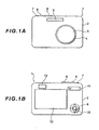
- FIG. 1 shows an external view of a digital camera 1 according to the present embodiment, and the general configuration of the digital camera 1 will be described first with reference to this drawing.
- the digital camara 1 has an imaging lens 3 installed in a lens barrel 4, and a stroboscopic emission unit 5, which emits auxiliary light when photographing light quantity is insufficient (when an object is dark), on a front face of the camera main unit 2 which is roughly a rectangular-parallelopiped.
- the release button 6 is a button that can select two levels, half pressed or full pressed, and if the release button 6 is half pressed, a photographing preparation operation, such as automatic exposure control (AE) and automatic focus control (AF), is executed, and if the release button 6 is full pressed, an image of the object is recorded.
- the power button 7 switches the power supply of the digital camera 1 ON/OFF by being depressed and held down.
- the mode dial 8 is a dial which can switch the operation mode of the digital camera 1 by a rotation operation, so that camera functions, such as display mode, setting mode and photographing mode, can be changed.
- the digital camera 1 has a portrait mode (for photographing an individual), distant view mode, night view mode and sports mode and the like, and photographing conditions are automatically controlled according to the selected photographing mode, so as to photograph appropriately for the respective photographing scene.
- the portrait mode is a photographing mode in which an individual is the primary object
- the distant view mode is a photographing mode in which a landscape is the object.
- a cross key 9, decision button 10, zoom button 11, liquid crystal monitor 12 and optical finder 13 are disposed on the rear surface of the camera main unit 2.
- the cross key 9 is controlled to select various menus and images displayed on the liquid crystal monitor 12.
- the decision button 10 is a button to operate when deciding the item selected by the cross key 9.
- the zoom button 11 is a button to optically and electronically zoom in on or zoom out from an image to be recorded upon being photographed.
- the liquid crystal monitor 12 is a liquid crystal display (LCD) to display an object as a video during photographing, or to display photographed and recorded images and various menu screens.
- the optical finder 13 is for optically confirming the object field.
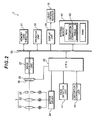
- Fig. 2 is a block diagram depicting the functions of the digital camera 1 according to the present embodiment.
- the digital camera 1 has an imaging lens 3, motor driver 24, image sensing element 25, image processing unit 27, memory card throttle 31, control unit 32, display unit 33, liquid crystal monitor 12, CPU 40, face detection unit 41, internal memory 42, distortion correction unit 44 and data bus 50 among others.
- the image processing unit 27, memory card throttle 31, operation unit 32, display unit 33, CPU 40 and internal memory 42 are connected via the data bus 50.
- the digital camera 1 also has a circuit unit to implement camera functions, but a description thereof is omitted.
- the imaging lens 3 is comprised of a zoom lens 21, focus lens 22, diaphragm 23 and so forth, and is a photographing optical system for forming an object image on a light receiving surface 26 of the image sensing element 25.
- the zoom lens 21 and focus lens 22 are disposed along the optical axis of the imaging lens 3 so as to freely move in the wide angle end side direction or telephoto end side direction.
- the zoom lens 21 is a lens that is moved by a motor according to the pressing operation of zoom button 11, so as to zoom in on or zoom out from (change photographing magnification of) the optical image formed on the image sensing element 25.
- the focus lens 22 is a lens that is moved by the motor according to the pressing operation of the zoom button 11, movement of the zoom lens 21 and half pressing operation of the release button 6, in order to control focus.
- the diaphragm 23 controls the light quantity of the object field that enters the image sensing element 25 by changing the diaphragm opening area according to the half pressing control of the release button 6.
- the motor driver 24 drives each motor based on the instruction of the CPU 40, so as to move the zoom lens 21 and focus lens 22 to predetermined positions, and control the opening state of the diaphragm 23.
- the image sensing element 25 is a solid image sensing element that is disposed on the back of the imagine lens 3, and is constituted by a CCD and CMOS, for example, to photo-electric converting an optical image of an object, which the imaging lens 3 formed on the light receiving surface 26, into electric signals, and outputting the analog imaging signals.
- the light receiving surface 26 is formed to be a rectangular shape having a long side in the lateral direction and a short side in the longitudinal direction.
- the image processing unit 27 removes noise from the analog electric signals that are output from the image sensing element 25, and performs analog/digital conversion to generate digital signals.
- the image processing unit 27 also performs interpolation processing on the digital signals converted from analog signals to generate image data for display, which is displayed on the liquid crystal monitor 12, and image data for recording.
- the memory card throttle 31 is a throttle which writes such data as photographed image in a memory card (storage medium) that is removably installed in the digital camera 1 or erases data in the memory card.
- the control unit 32 has a release button 6, power button 7, mode dial 8, cross key 9, decision button 10, zoom button 11 and so forth, and detects the half press operation and full press operation of the release button 6 or the like.
- the display unit 33 generates screen data based on the instruction from the CPU 40, and displays this image data on the liquid crystal monitor 12 disposed on the rear face side of the digital camera 1.
- the CPU 40 is a circuit which processes the control programs for implementing various functions executed by the digital camera 1.
- the CPU 40 reads and executes the control programs stored in the CPU memory and the internal memory 42, so as to comprehensively control each unit in the digital camera 1.
- the face detection unit 41 extracts an individual by analyzing the characteristic quantities of an individual on the image data captured by the image sensing element 25, and detects the face area of the object.
- the face detection unit 41 specifies the size and position of a face of an individual in the photographed image by extracting the pupils (eyes) of the individual and the contour of the face, for example. If the face detection unit 41 recognizes a face in the image data, the CPU 40 performs focus control for focusing the focal point of the imaging lens 3 on the face area, exposure control to adjust exposure of the face area to the optimum, and so forth.
- the internal memory 42 is comprised of a ROM, which stores control programs (firmware) to have the CPU 40 execute various processings, RAM, which stores various data including image data captured by the image sensing element 25, and the like.
- the internal memory 42 stores a face detection program which is executed for detecting the face area of the object, and can also store facial information of the object, such as face position and face size acquired by the face recognition processing.
- the distortion correction table 43 that is used for correcting distortion of the captured image, is stored.
- the later mentioned distortion correction unit 44 stores the coefficients of the distortion correction functions that are read when the distortion of photographed images are corrected.
- the distortion correction unit 44 performs image transformation processing on the photographed image data using a predetermined distortion correction function so as to correct the distortion generated by the distortion of the imaging lens 3.
- r denotes an image height from the center of the image before image transformation processing
- An (A 0 , A 1 , A 2 , A 3 , ...) is a polynomial coefficient (distortion coefficient) in each term of a degree, and is stored in the distortion correction table 43.
- the present invention is not limited to this, but may be constructed such that a data table of the distortion data of the imaging lens 3 is created for each position (pixel position) of the captured image, and is stored in the distortion correction table 43, and is read by the distortion correction unit 44 to perform image transformation processing (distortion correction) on the photographed image data.
- a pin cushion distortion or barrel distortion is generated on an image captured based on the projection system according to Expression (2), because of the distortion of the imaging lens 3 generated due to the difference of the image forming magnification between the center portion and edge portion of the image frame (barrel distortion in particular tends to be generated in the wide angle end of the lens).
- the distortion correction unit 44 performs image transformation processing on the photographed image data using the distortion correction function dis (r) shown in Expression (1), as mentioned above, then a less distorted image can be acquired.
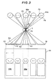
- Fig. 3 is a diagram depicting the wide angle distortion of an object image photographed at the edge portion of a screen, and how the wide angle distortion is generated will be described referring to this diagram. If a three-dimensional object is an individual, a head portion of the individual is regarded as a spherical shape, and the body portion is regarded as a cylindrical shape, and as shown in Fig. 3 if individuals are lined up side by side in front of the digital camera 1 and photographed, individual photographed at the edge portions are laterally enlarged by 1/cos ⁇ , where ⁇ is an incident angle.
- a triangle P0P1P2 created by segment P1P2 that is a diameter of this individual (approximated by the spherical or cylindrical body) 60a and the center of the imaging lens P0, and a triangle P0P1'P2' created by an image P1'P2' of the segment P1P2, formed on the light receiving surface 26, and the center of the imaging lens P0, are similar figures, therefore the image of this individual 60a is formed on the light receiving surface 26 as an ideal image.
- a triangle P0P3P4 created by a segment P3P4 that is a diameter of this individual (approximated by the spherical or cylindrical body) 60b and the center of the imaging lens P0, and a triangle P0P3'P5' created by an image P3'P5' of the segment P3P4, formed on the light receiving surface 26 and the center of the imaging lens P0 are not similar figures, and an image of the segment P3P4 is formed on the light receiving surface 26 as the segment P3'P5', that is a segment when the ideally scaled segment P3'P4' is enlarged. This is the reason why an image of an individual positioned at the edge portion of a screen is photographed in a laterally enlarged state, and looks broader as shown in Fig. 3 .
- the distortion correction unit 44 not only performs distortion correction generated by the distortion of the imaging lens, but also performs image transformation processing for transforming the image data captured by the image sensing element 25 into an image in another projection system described next.
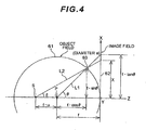
- Fig. 4 is a diagram depicting a projection method applied to the present embodiment for the distortion correction unit 44 to perform image transformation processing.
- an object object field
- the object image image field
- the distance; between the center P of the sphere 61 and the plane 62 (contact point thereon) is denoted by the focal length f
- an XYZ rectangular coordinate system is set as illustrated, where the Y axis is set in a direction perpendicular to the page face, the X axis is set, along with the Y axis, to be parallel with the plane, and the Z axis is set to be perpendicular to the plane.
- This projection system for image transformation can be represented by the line L2 from the point S, that is distant from the point P by the distance f • u along the Z axis (u is an arbitrary variable), to the plane 62 (XY plane), and the height x of the intersection of this line L2 and the plane 62 is the image height of the object in the image field.
- this projection system is expressed by the following expression.
- ⁇ x can be, in general, expressed by the following Expression (7).
- ⁇ x a • f ⁇ u + 1 ⁇ cos ⁇ - ⁇ / u + cos ⁇ • cos ⁇
- ⁇ y a • f / cos ⁇
- u is a function that depends on ⁇ , and in order to acquire a uniform image with less wide angle distortion, it is preferable that u satisfies the conditions of the following Expression (13) in Expression (5) that expresses image height x. 0.3 ⁇ u ⁇ 0.7
- the upper limit value of the conditional Expression (13) is 0.65. Also to ensure the effect of the present embodiment, it is preferable that the lower limit value of the conditional Expression (13) is 0.35.
- the distortion correction unit 44 executes the image transformation processing for transforming an image captured based on the projection system shown in Expression (2) into an image based on a projection system that satisfies Expression (5) and Expression (13), and can easily acquire an image of which distortion is appropriately decreased.
- the distortion correction unit 44 it is preferable to execute the image transformation processing by the distortion correction unit 44 when the photographing conditions satisfy (a) the photographing mode selected by the mode dial 8 is portrait mode in which the object is assumed to be an individual, (b) the face detection unit 41 recognizes a face of an individual in the image captured by the image sensing element 25, or (c) the face detection unit 41 recognizes a face of an individual in an edge portion of the image for example.
- This is to ensure the effect of preventing the above mentioned problem of an image of an individual (particularly an individual at the edge portion of a screen) being enlarged, by correcting the wide angle distortion on an image photographed when the primary photographed object is an individual.
- Fig. 5 is a flow chart depicting the photographing operation of the digital camera 1
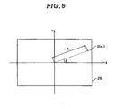
- Fig. 6 is a diagram depicting the coordinate system of the light receiving surface 26 (image frame) of the image sensing element 25.
- the CPU 40 controls the image processing unit 27, display unit 33 or the like to display the video image of the object on the liquid crystal monitor 12 as a through picture.
- the user confirms the video image displayed on the liquid crystal monitor 12, and determines the photographing composition.
- step S101 If the user instructs photographing preparation by half pressing the release button 6 when the thorough image is displayed on the liquid crystal monitor 12 (step S101), the face detection unit 41 executes face recognition processing based on the image that is input from the image processing unit 27 (step S102). If the user then instructs photographing by full pressing the release button 6, the CPU 40 executes photographing processing, such as exposure operation, so that exposure of the photographed image becomes the optimum (step S103).
- step S104 it is judged whether the photographing mode, which was selected by the mode dial 8 before photographing, is portrait mode or not, and if portrait mode is selected, that is, step S104 is YES, processing advances to step S106. If another photographing mode is selected, that is, step S104 is NO, processing advances to step S105, and it is judged whether a face of an individual is recognized in the photographed image as a result of the face recognition processing in step S102.
- the case of a face being recognized means a case of a face being recognized somewhere in the image frame regardless the position, but is not limited to this, and may be a case of a face being recognized only at the edge portion of the image frame. If step S105 is YES, that is if a face of an individual is recognized in step S102, processing advances to step S106.
- step S106 the CPU 40 acquires an image (imaging signal) from the image sensing element 25 and inputs the image to the image processing unit 27, and acquires the image on which the image processing unit 27 executed the above mentioned image processing.
- the distortion correction unit 44 performs coordinate transformation processing for transforming the coordinate system on the light receiving surface 26 of the image sensing element 25 from the rectangular coordinate system, which is an X axis (axis in the long side (lateral) direction of the light sensing element 25) and Y axis (axis in the short side (longitudinal) direction of the image sensing element 25) with the center of the light receiving surface as a reference, into a polar coordinate system (step S107).
- the distortion correction unit 44 connects the distortion of the image data of which coordinate was transformed, into this polar coordinate (r, ⁇ ) based on the distortion of the imaging lens 3 (step S108).
- step S109 a processing to retransform (return) this polar coordinate (r', ⁇ ') to the coordinate (x' y') on the XY coordinate system corresponding to the light receiving surface 26 is performed (step S109).
- ⁇ x atan x / f
- f denotes a focal length of the imaging lens 3 with respect to x', that is the distance (image height) from the image center along the X axis direction (step S110).
- the distance x' from the image center is applied to the conditional Expression (5) above, described using the transformation coefficient u of the projection system (step S111), and the coordinate (x", y") after being transformed into an image in the projection system based on Expression (5) is given by the following Expressions (5)' and (22) (step S112).
- step S106' If a face is not detected in an image and step S105 resulted in NO (that is, if both step S104 and step S105 resulted in NO), processing advances to step S106'.
- Step S106' to step s109' are the same as the above mentioned processings in step S106 to step S109, which is the general distortion correction flow, therefore redundant description is omitted here.
- the CPU 40 then compresses the image-transformed image data, and records it in the internal memory 42 (RAM) (step S113).
- the CPU 40 displays this image acquired by photographing on the liquid crystal monitor 12 only for a predetermined time. Thereby a series of photographing operations by the digital camera 1 ends.
- the acquired image is transformed into an image in the projection system shown in Expression (5) or the like, so as to correct wide angle distortion appropriately, whereby a uniform image which is free from linear distortion in the horizontal and vertical directions and has less distortion of an individual at the edge portion of a screen can be acquired.
- some distortion may be generated in diagonal lines, although the distortions of the horizontal and vertical lines are improved, and also when a regular pattern, such as tiles on a wall, is photographed, the pattern at the edge portion of the screen may become slightly elongated. Therefore this digital camera 1 is most appropriate when a major object to be photographed is an individual
- wide angle distortion correction processing on a captured image only in the X direction (long side direction) was described, but the present invention is not limited to this, and wide angle distortion may also be corrected for the Y axis direction (short side direction), or for both the X and Y axis directions by applying the conditional Expressions (5) and (13) to the Y direction as well.
- the distortion correction unit 44 executes image transformation processing for wide angle distortion correction only when the selected photographing mode is portrait mode, or when a face is recognized in an image, but the present invention is not limited to this, and image transformation processing may be performed when another photographing mods (e,g. night view portrait mode) is selected.
- another photographing mods e.g. night view portrait mode
- the image transformation processing to transform an image captured by a normal projection system into an image in the above mentioned predetermined projection system is not limited to the processing by a digital camera 1 (distortion correction unit thereof), but an image photographed by a camera may be transformed by a computer (image processor) having a CPU, for example, and needless to say, similar effect can be implemented.
- This method has an image acquisition step of acquiring an image formed by the photographing optical system and a distortion correction step of correcting distortion generated in the image based on a focal length of the photographing optical system and an incident angle ⁇ of a ray from an object to the photographing optical system, and the distortion correction performed in this distortion correction step is executed by changing the amount of correction according to the focal length of the photographing optical system and the incident angle ⁇ .
Landscapes
- Engineering & Computer Science (AREA)
- Multimedia (AREA)
- Signal Processing (AREA)
- Image Processing (AREA)
- Studio Devices (AREA)
- Image Analysis (AREA)
Description
- This invention claims the benefit of Japanese Patent Application No.
2009-067811 - The present invention relates to a camera having a distortion correction function for a photographed image, and an image correction method.
- In an imaging device, such as a digital camera, it is known that a photographed image is distorted by the distortion of the photographing optical system. This is due to the difference of imaging magnification between the center portion and edge portion of an image, and in the photographing optical system, a pin cushion distortion is generated in photographing in the telephoto state, and a barrel distortion is generated in photographing in the wide angle state. Digital cameras, on the other hand, have characteristic to acquire images as digital data, and various technologies to correct distortion by performing image processing (digital processing) on the image data have been proposed (e.g. see Japanese Patent Application Laid-Open No.
2008-99184 -
EP 2015248 relates to an image processing method capable of attaining line reproducibility and magnification distortion reduction in a well-balanced manner in an image. - The image processing method performs predetermined geometric transformation processing on an image to be processed, in which the predetermined geometric transformation processing includes geometric transformation processing for magnification distortion reduction that reduces the discrepancy between circumferential magnification and radial magnification of the image to be processed and at least one parameter; that determines the strength or content of the predetermined geometric transformation processing is set according to the structure of the image to be processed.
-
US 2008/0239107 relates to a digital camera including a distortion correction section. Wide-angle distortion and optical distortion are evaluated, and coefficients are selected from tables and used to correct the distortion. -
US 2005/0083427 relates to a camera unit having a lens unit configured so that an amount of change in image height in an image formed on a pickup element with respect to a change in the incident angle of light rays is greater at a peripheral portion than at a center portion of the image. - However if distortions are corrected as above, it means that the object can be photographed without distortion two-dimensionally, while the distortion still remains in the object viewed three-dimensionally. For example, when a commemorative photo or group shot is taken at a sightseeing location, a wide angle lens is frequently used for the photographing optical system in order to shoot the background as widely as possible. In such a case, as shown in
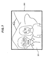
Fig. 7 , as the photographing angle becomes wider the image of an individual 201 to be shot in the edge portion of the photographedimage 200 is enlarged horizontally, and it looks broader, that is an image distortion problem called, "perspective distortion" or "wide angle distortion" is generated, and the problem is how to implement a high quality image free from such distortion. - With the foregoing in view, it is an object of the present invention to provide a camera having a configuration to decrease distortion generated in photographed images at high precision, and an image correction method.
- Aspects of the present invention are set out in the appended claims.
- According to the present invention, a camera, an apparatus and an image correction method for acquiring a uniform image of which distortions are decreased at high precision, can be implemented.
- Further scope of applicability of the present invention will become apparent from the detailed description given hereinafter.
- The present invention will become more fully understood from the detailed description given herein below and the accompanying drawings which are given by way of illustration only and thus are not limitative of the present invention.
-
Fig. 1 are external views of a camera according to an embodiment of the present invention, where A ofFig.1 is a front view and B ofFig.1 is a rear view; -
Fig. 2 is a block diagram depicting a configuration of the camera according to the embodiment; -
Fig. 3 is a diagram depicting a wide angle distortion of object images photographed on the edge of the screen; -
Fig. 4 is a diagram depicting a projection system used for the image transformation processing in the camera of the embodiment; -
Fig. 5 is a flow chart depicting the operation of the camera of the embodiment; -
Fig. 6 is a diagram showing the coordinate system on a light receiving surface; and -
Fig. 7 is a drawing to show the wide angle distortion in an image photographed by a conventional camera. -
Fig. 8 is a flow chart depicting an image correction method according to an embodiment of the present invention. - Embodiments of the present invention will now be described with reference to the drawings.
Fig. 1 shows an external view of adigital camera 1 according to the present embodiment, and the general configuration of thedigital camera 1 will be described first with reference to this drawing. - The
digital camara 1 has animaging lens 3 installed in alens barrel 4, and astroboscopic emission unit 5, which emits auxiliary light when photographing light quantity is insufficient (when an object is dark), on a front face of the cameramain unit 2 which is roughly a rectangular-parallelopiped. - On the top face of the camera
main unit 2, arelease button 6,power button 7 and amode dial 8, among others, are disposed. Therelease button 6 is a button that can select two levels, half pressed or full pressed, and if therelease button 6 is half pressed, a photographing preparation operation, such as automatic exposure control (AE) and automatic focus control (AF), is executed, and if therelease button 6 is full pressed, an image of the object is recorded. Thepower button 7 switches the power supply of thedigital camera 1 ON/OFF by being depressed and held down. - The
mode dial 8 is a dial which can switch the operation mode of thedigital camera 1 by a rotation operation, so that camera functions, such as display mode, setting mode and photographing mode, can be changed. As photographing modes, thedigital camera 1 has a portrait mode (for photographing an individual), distant view mode, night view mode and sports mode and the like, and photographing conditions are automatically controlled according to the selected photographing mode, so as to photograph appropriately for the respective photographing scene. For example, the portrait mode is a photographing mode in which an individual is the primary object, and the distant view mode is a photographing mode in which a landscape is the object. - On the rear surface of the camera
main unit 2, across key 9,decision button 10,zoom button 11,liquid crystal monitor 12 andoptical finder 13 are disposed. Thecross key 9 is controlled to select various menus and images displayed on theliquid crystal monitor 12. Thedecision button 10 is a button to operate when deciding the item selected by thecross key 9. Thezoom button 11 is a button to optically and electronically zoom in on or zoom out from an image to be recorded upon being photographed. Theliquid crystal monitor 12 is a liquid crystal display (LCD) to display an object as a video during photographing, or to display photographed and recorded images and various menu screens. Theoptical finder 13 is for optically confirming the object field. -
Fig. 2 is a block diagram depicting the functions of thedigital camera 1 according to the present embodiment. AsFig. 2 shows, thedigital camera 1 has animaging lens 3,motor driver 24,image sensing element 25,image processing unit 27,memory card throttle 31,control unit 32,display unit 33,liquid crystal monitor 12,CPU 40,face detection unit 41,internal memory 42,distortion correction unit 44 anddata bus 50 among others. Theimage processing unit 27,memory card throttle 31,operation unit 32,display unit 33,CPU 40 andinternal memory 42 are connected via thedata bus 50. Needless to say, thedigital camera 1 also has a circuit unit to implement camera functions, but a description thereof is omitted. - The
imaging lens 3 is comprised of azoom lens 21,focus lens 22,diaphragm 23 and so forth, and is a photographing optical system for forming an object image on alight receiving surface 26 of theimage sensing element 25. Thezoom lens 21 andfocus lens 22 are disposed along the optical axis of theimaging lens 3 so as to freely move in the wide angle end side direction or telephoto end side direction. Thezoom lens 21 is a lens that is moved by a motor according to the pressing operation ofzoom button 11, so as to zoom in on or zoom out from (change photographing magnification of) the optical image formed on theimage sensing element 25. Thefocus lens 22 is a lens that is moved by the motor according to the pressing operation of thezoom button 11, movement of thezoom lens 21 and half pressing operation of therelease button 6, in order to control focus. Thediaphragm 23 controls the light quantity of the object field that enters theimage sensing element 25 by changing the diaphragm opening area according to the half pressing control of therelease button 6. Themotor driver 24 drives each motor based on the instruction of theCPU 40, so as to move thezoom lens 21 andfocus lens 22 to predetermined positions, and control the opening state of thediaphragm 23. - The
image sensing element 25 is a solid image sensing element that is disposed on the back of theimagine lens 3, and is constituted by a CCD and CMOS, for example, to photo-electric converting an optical image of an object, which theimaging lens 3 formed on thelight receiving surface 26, into electric signals, and outputting the analog imaging signals. Thelight receiving surface 26 is formed to be a rectangular shape having a long side in the lateral direction and a short side in the longitudinal direction. - The
image processing unit 27 removes noise from the analog electric signals that are output from theimage sensing element 25, and performs analog/digital conversion to generate digital signals. Theimage processing unit 27 also performs interpolation processing on the digital signals converted from analog signals to generate image data for display, which is displayed on theliquid crystal monitor 12, and image data for recording. Thememory card throttle 31 is a throttle which writes such data as photographed image in a memory card (storage medium) that is removably installed in thedigital camera 1 or erases data in the memory card. - The
control unit 32 has arelease button 6,power button 7,mode dial 8,cross key 9,decision button 10,zoom button 11 and so forth, and detects the half press operation and full press operation of therelease button 6 or the like. Thedisplay unit 33 generates screen data based on the instruction from theCPU 40, and displays this image data on the liquid crystal monitor 12 disposed on the rear face side of thedigital camera 1. - The
CPU 40 is a circuit which processes the control programs for implementing various functions executed by thedigital camera 1. TheCPU 40 reads and executes the control programs stored in the CPU memory and theinternal memory 42, so as to comprehensively control each unit in thedigital camera 1. - The
face detection unit 41 extracts an individual by analyzing the characteristic quantities of an individual on the image data captured by theimage sensing element 25, and detects the face area of the object. Theface detection unit 41 specifies the size and position of a face of an individual in the photographed image by extracting the pupils (eyes) of the individual and the contour of the face, for example. If theface detection unit 41 recognizes a face in the image data, theCPU 40 performs focus control for focusing the focal point of theimaging lens 3 on the face area, exposure control to adjust exposure of the face area to the optimum, and so forth. - The
internal memory 42 is comprised of a ROM, which stores control programs (firmware) to have theCPU 40 execute various processings, RAM, which stores various data including image data captured by theimage sensing element 25, and the like. Theinternal memory 42 stores a face detection program which is executed for detecting the face area of the object, and can also store facial information of the object, such as face position and face size acquired by the face recognition processing. In the ROM of theinternal memory 42, the distortion correction table 43, that is used for correcting distortion of the captured image, is stored. - In the distortion correction table 43, the later mentioned
distortion correction unit 44 stores the coefficients of the distortion correction functions that are read when the distortion of photographed images are corrected. - The
distortion correction unit 44 performs image transformation processing on the photographed image data using a predetermined distortion correction function so as to correct the distortion generated by the distortion of theimaging lens 3. For example, the distortion correction function dis (r) can be represented by the following polynomial:
- Here, r denotes an image height from the center of the image before image transformation processing, and An (A0, A1, A2, A3, ...) is a polynomial coefficient (distortion coefficient) in each term of a degree, and is stored in the distortion correction table 43. The present invention is not limited to this, but may be constructed such that a data table of the distortion data of the
imaging lens 3 is created for each position (pixel position) of the captured image, and is stored in the distortion correction table 43, and is read by thedistortion correction unit 44 to perform image transformation processing (distortion correction) on the photographed image data. - In the
digital camera 1 constructed as above, a projection system of theimaging lens 3 is used according to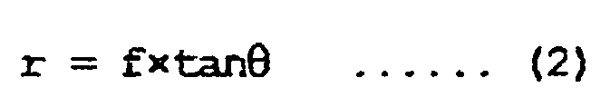
where r denotes an image height of theimage sensing element 25 on thelight receiving surface 26, f denotes a focal length of theimaging lens 3, and θ denotes an incident angle (half angle of view) from the object. - Generally a pin cushion distortion or barrel distortion is generated on an image captured based on the projection system according to Expression (2), because of the distortion of the
imaging lens 3 generated due to the difference of the image forming magnification between the center portion and edge portion of the image frame (barrel distortion in particular tends to be generated in the wide angle end of the lens). To correct this distortion, thedistortion correction unit 44 performs image transformation processing on the photographed image data using the distortion correction function dis (r) shown in Expression (1), as mentioned above, then a less distorted image can be acquired. - However this means that a two-dimensional object can be photographed without distortion, but in the case of a three-dimensional object, distortion in which the image of an object at the edge portion of the image frame is enlarged (this is generally called "perspective distortion" or "wide angle distortion", and is referred to as "wide angle distortion" in the following description) is still generated separately from the above mentioned distortion.
-
Fig. 3 is a diagram depicting the wide angle distortion of an object image photographed at the edge portion of a screen, and how the wide angle distortion is generated will be described referring to this diagram. If a three-dimensional object is an individual, a head portion of the individual is regarded as a spherical shape, and the body portion is regarded as a cylindrical shape, and as shown inFig. 3 if individuals are lined up side by side in front of thedigital camera 1 and photographed, individual photographed at the edge portions are laterally enlarged by 1/cos θ, where θ is an incident angle. - In the case of an individual 60a positioned directly in front of the
imaging lens 3, a triangle P0P1P2 created by segment P1P2 that is a diameter of this individual (approximated by the spherical or cylindrical body) 60a and the center of the imaging lens P0, and a triangle P0P1'P2' created by an image P1'P2' of the segment P1P2, formed on thelight receiving surface 26, and the center of the imaging lens P0, are similar figures, therefore the image of this individual 60a is formed on thelight receiving surface 26 as an ideal image. In the case of an individual 60b positioned at the edge portion, on the other hand, a triangle P0P3P4 created by a segment P3P4 that is a diameter of this individual (approximated by the spherical or cylindrical body) 60b and the center of the imaging lens P0, and a triangle P0P3'P5' created by an image P3'P5' of the segment P3P4, formed on thelight receiving surface 26 and the center of the imaging lens P0 are not similar figures, and an image of the segment P3P4 is formed on thelight receiving surface 26 as the segment P3'P5', that is a segment when the ideally scaled segment P3'P4' is enlarged. This is the reason why an image of an individual positioned at the edge portion of a screen is photographed in a laterally enlarged state, and looks broader as shown inFig. 3 . - Therefore in order to decrease this wide angle distortion of a three-dimensional object image, a projection system, with which the horizontal (lateral) size and vertical (longitudinal) size of an image formed on the
light receiving surface 26 of theimage sensing element 25 match with those of a three-dimensional (spherical) object, should be selected. According to thedigital camera 1 of the present embodiment, thedistortion correction unit 44 not only performs distortion correction generated by the distortion of the imaging lens, but also performs image transformation processing for transforming the image data captured by theimage sensing element 25 into an image in another projection system described next. -
Fig. 4 is a diagram depicting a projection method applied to the present embodiment for thedistortion correction unit 44 to perform image transformation processing. When an object (object field) is represented by asphere 61 of which center is the point P, the object image (image field) is represented by aplane 62 contacting the sphere, and the distance; between the center P of thesphere 61 and the plane 62 (contact point thereon) (in other words, the radius of the sphere 61) is denoted by the focal length f, the projection system of the normal lens shown in Expression (2) (r = f • tan θ) is represented by the line L1 from the point P to theplane 62. InFig. 4 , an XYZ rectangular coordinate system is set as illustrated, where the Y axis is set in a direction perpendicular to the page face, the X axis is set, along with the Y axis, to be parallel with the plane, and the Z axis is set to be perpendicular to the plane. - This projection system for image transformation, on the other hand, can be represented by the line L2 from the point S, that is distant from the point P by the distance f • u along the Z axis (u is an arbitrary variable), to the plane 62 (XY plane), and the height x of the intersection of this line L2 and the
plane 62 is the image height of the object in the image field. In other words, this projection system is expressed by the following expression.
where δ denotes an angle formed by the Z axis and the line L2. Since asFig. 4 shows,

- In Expression (5), x = f • tan θ is established when u = O, that is, a normal projection system, x = 2f • sin (θ/2) is established when u = 1, that is, a stereographic projection system, and x = f • sin θ is established when u = co, that is, an orthogonal projection system. This means that if an optimum projection system is derived by appropriately selecting the value u, the image height x can be changed, and an image with less wide angle distortion can be acquired. In the description herein below, u is called a "transformation coefficient" of a projection system.
- A condition to acquire an image free from distortion, in a case of an image of an
object 63 represented by a small disk with diameter a in the object field, is that the size Δx in the X axis direction and the size Δy in the Y axis direction of this image in the image field must be the same, that is
- In this case, Δx can be, in general, expressed by the following Expression (7).

- If Expression (7) is transformed; so as to eliminate δ using the fundamental expression of the trigonometric function, then Δ x can be transformed as follows.

- The size Δy of the image of the
object 63 in the Y axis direction, on the other hand, can be given by the following Expression (9), because of the condition that the horizontal line (lateral line) of the two-dimensional object is not distorted near the X axis (Y = 0).
- Therefore the following Expression (10) can be acquired by substituting Expression (8) and Expression (9) for Δx = Δy, which is the above mentioned conditional Expression (6).

- This expression (10) can be transformed and simplified to become the following Expression (11), although some steps are omitted.

u is solved as follows by using Expression (10):
which shows that u is a function that depends only on the incident angle θ. - According to Expression (12), u = 0.5 if θ = 0°, and u = 0.46 if 0° < θ ≤ 45°, therefore these u values are good values to correct a wide angle distortion under the respective conditions. If θ is greater than 45°, u becomes a value smaller than 0.46. The above description is based on the assumption that the distortion in an image near the X axis is decreased, but needless to say, wide angle distortion can be decreased for an image in a position distant from the X axis by appropriately selecting u.
- As described above, u is a function that depends on θ, and in order to acquire a uniform image with less wide angle distortion, it is preferable that u satisfies the conditions of the following Expression (13) in Expression (5) that expresses image height x.

- When u satisfies the conditional Expression (13), the image height x satisfies the following expression in Expression (5):

and it is shown that the present projection system in which u is appropriately selected to satisfy the conditional expression (13) is a projection system between a conformal projection system (x = f • θ) and a normal lens projection system (x = f tan θ). - To ensure the effect of the present embodiment, it is preferable that the upper limit value of the conditional Expression (13) is 0.65. Also to ensure the effect of the present embodiment, it is preferable that the lower limit value of the conditional Expression (13) is 0.35.
- In this way, the
distortion correction unit 44 executes the image transformation processing for transforming an image captured based on the projection system shown in Expression (2) into an image based on a projection system that satisfies Expression (5) and Expression (13), and can easily acquire an image of which distortion is appropriately decreased. - According to the present embodiment, it is preferable to execute the image transformation processing by the
distortion correction unit 44 when the photographing conditions satisfy (a) the photographing mode selected by themode dial 8 is portrait mode in which the object is assumed to be an individual, (b) theface detection unit 41 recognizes a face of an individual in the image captured by theimage sensing element 25, or (c) theface detection unit 41 recognizes a face of an individual in an edge portion of the image for example. This is to ensure the effect of preventing the above mentioned problem of an image of an individual (particularly an individual at the edge portion of a screen) being enlarged, by correcting the wide angle distortion on an image photographed when the primary photographed object is an individual. - Now an example of an operation of the
digital camera 1 according to the present embodiment having the above mentioned configuration will be described with reference toFig. 5 andFig. 6 .Fig. 5 is a flow chart depicting the photographing operation of thedigital camera 1, andFig. 6 is a diagram depicting the coordinate system of the light receiving surface 26 (image frame) of theimage sensing element 25. - When the user operates the
power button 7, whereby the power of thedigital camera 1 is turned ON and the operation mode is set to photographing mode, theCPU 40 controls theimage processing unit 27,display unit 33 or the like to display the video image of the object on the liquid crystal monitor 12 as a through picture. The user confirms the video image displayed on theliquid crystal monitor 12, and determines the photographing composition. - If the user instructs photographing preparation by half pressing the
release button 6 when the thorough image is displayed on the liquid crystal monitor 12 (step S101), theface detection unit 41 executes face recognition processing based on the image that is input from the image processing unit 27 (step S102). If the user then instructs photographing by full pressing therelease button 6, theCPU 40 executes photographing processing, such as exposure operation, so that exposure of the photographed image becomes the optimum (step S103). - In step S104, it is judged whether the photographing mode, which was selected by the
mode dial 8 before photographing, is portrait mode or not, and if portrait mode is selected, that is, step S104 is YES, processing advances to step S106. If another photographing mode is selected, that is, step S104 is NO, processing advances to step S105, and it is judged whether a face of an individual is recognized in the photographed image as a result of the face recognition processing in step S102. The case of a face being recognized means a case of a face being recognized somewhere in the image frame regardless the position, but is not limited to this, and may be a case of a face being recognized only at the edge portion of the image frame. If step S105 is YES, that is if a face of an individual is recognized in step S102, processing advances to step S106. - In step S106, the
CPU 40 acquires an image (imaging signal) from theimage sensing element 25 and inputs the image to theimage processing unit 27, and acquires the image on which theimage processing unit 27 executed the above mentioned image processing. Then thedistortion correction unit 44 performs coordinate transformation processing for transforming the coordinate system on thelight receiving surface 26 of theimage sensing element 25 from the rectangular coordinate system, which is an X axis (axis in the long side (lateral) direction of the light sensing element 25) and Y axis (axis in the short side (longitudinal) direction of the image sensing element 25) with the center of the light receiving surface as a reference, into a polar coordinate system (step S107). In this coordinate transformation processing, the coordinate (x, y) of an arbitrary point (pixel) Q on thelight receiving surface 26 is transformed into a polar coordinate (r, α) given by the following Expressions (15) and (16).

- Then the
distortion correction unit 44 connects the distortion of the image data of which coordinate was transformed, into this polar coordinate (r, α) based on the distortion of the imaging lens 3 (step S108). Each value of the polar coordinate (r' α') after distortion correction is given by the following expressions using the above mentioned distortion correction function dis (r) of Expression (1):
- In this distortion correction, the angle α' formed by the reference axes X and Y does not change, and only the size of the image height r' after correction is changed.
- Then a processing to retransform (return) this polar coordinate (r', α') to the coordinate (x' y') on the XY coordinate system corresponding to the
light receiving surface 26 is performed (step S109).

- Up to this point marks the flow of general distortion correction, and from this point on marks the flow of wide angle distortion correction according to the present embodiment. To simplify description, the wide angle distortion correction processing of an image in the X axis direction (long side direction) will be described as an example.
- The incident angle θx from the object is given by

where f denotes a focal length of theimaging lens 3 with respect to x', that is the distance (image height) from the image center along the X axis direction (step S110). The distance x' from the image center is applied to the conditional Expression (5) above, described using the transformation coefficient u of the projection system (step S111), and the coordinate (x", y") after being transformed into an image in the projection system based on Expression (5) is given by the following Expressions (5)' and (22) (step S112).
- Here an image compressed in the X axis direction (lateral direction), of which wide angle distortion has been appropriately corrected, can be acquired by appropriately selecting the transformation coefficient u of the projection system given by Expression (5)' within the range of the above mentioned conditional Expression (13).
- If a face is not detected in an image and step S105 resulted in NO (that is, if both step S104 and step S105 resulted in NO), processing advances to step S106'. Step S106' to step s109' are the same as the above mentioned processings in step S106 to step S109, which is the general distortion correction flow, therefore redundant description is omitted here.
- The
CPU 40 then compresses the image-transformed image data, and records it in the internal memory 42 (RAM) (step S113).
TheCPU 40 displays this image acquired by photographing on the liquid crystal monitor 12 only for a predetermined time. Thereby a series of photographing operations by thedigital camera 1 ends. - According to the
digital camera 1 of the present embodiment, the acquired image is transformed into an image in the projection system shown in Expression (5) or the like, so as to correct wide angle distortion appropriately, whereby a uniform image which is free from linear distortion in the horizontal and vertical directions and has less distortion of an individual at the edge portion of a screen can be acquired. - According to the
digital camera 1 of the present embodiment, some distortion may be generated in diagonal lines, although the distortions of the horizontal and vertical lines are improved, and also when a regular pattern, such as tiles on a wall, is photographed, the pattern at the edge portion of the screen may become slightly elongated. Therefore thisdigital camera 1 is most appropriate when a major object to be photographed is an individual - In the above embodiment, wide angle distortion correction processing on a captured image only in the X direction (long side direction) was described, but the present invention is not limited to this, and wide angle distortion may also be corrected for the Y axis direction (short side direction), or for both the X and Y axis directions by applying the conditional Expressions (5) and (13) to the Y direction as well.
- In the above embodiment, the
distortion correction unit 44 executes image transformation processing for wide angle distortion correction only when the selected photographing mode is portrait mode, or when a face is recognized in an image, but the present invention is not limited to this, and image transformation processing may be performed when another photographing mods (e,g. night view portrait mode) is selected. - In the above embodiment, functional blocks, such as the
face detection unit 41 and thedistortion correction unit 44, are disposed inFig. 2 to simplify description, but according to the present embodiment, the CPU implements each function based on a predetermined control program. - The image transformation processing to transform an image captured by a normal projection system into an image in the above mentioned predetermined projection system is not limited to the processing by a digital camera 1 (distortion correction unit thereof), but an image photographed by a camera may be transformed by a computer (image processor) having a CPU, for example, and needless to say, similar effect can be implemented.
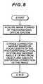
- Now the image correction method according to an embodiment of the present invention will be described with reference to the flow chart in
Fig. 8 . - This method has an image acquisition step of acquiring an image formed by the photographing optical system and a distortion correction step of correcting distortion generated in the image based on a focal length of the photographing optical system and an incident angle θ of a ray from an object to the photographing optical system, and the distortion correction performed in this distortion correction step is executed by changing the amount of correction according to the focal length of the photographing optical system and the incident angle θ.
Claims (9)
- A camera (1), comprising:a processing unit (27) which, when distortion of an image formed by a photographing optical system is corrected based on a focal length f of the photographing optical system and an incident angle 0 of a ray from an object to the photographing optical system, is adapted to change an amount of the correction of the distortion of an image according to the focal length f and the incident angle θ,characterised in thatthe processing unit (27) is adapted to execute the image distortion correction according to a projection system that satisfies the expression:
 where u is appropriately selected to satisfy the expression 0.3 < u < 0.7where x denotes an image height from a center of the image along one direction out of a long side direction and a short side direction of the image, which cross each other orthogonally, and u denotes a transformation coefficient of the projection system.
 - The camera (1) according to Claim 1, further comprising a face detection unit (41) adapted to detect a face in the object, wherein
the processing unit (27) is adapted to change the amount of correction when the face detection unit (41) detects a face in the image of the object. - The camera (1) according to Claim 2, wherein
the processing unit (27) is adapted to change the amount of correction when the face detection unit (41) detects a face at least in an edge portion of the image. - The camera (1) according to Claim 1, further comprising a portrait mode in which the object is assumed to be an individual, wherein
the processing unit (27) is adapted to change the amount of correction when the portrait mode is applied. - The camera (1) according to Claim 4, further comprising a face detection unit (41) adapted to detect a face in the object, wherein
the processing unit (27) is adapted to
detect a face at least in an edge portion of the image of the object. - The camera (1) according to Claim 1, wherein
the processing unit (27) has first and second correction patterns, the amounts of correction of which are different,
the processing unit (27) is adapted to execute distortion correction using the
first correction pattern, according to a projection system that satisfies the expression:
where y denotes an image height of an image generated by the photographing optical system, from a center of the image along one direction out of a long side direction and a short side direction of the image, which cross each other orthogonally, 0 denotes an incident angle from the object to the photographing optical system, and f denotes a focal length of the photographing optical system, and
the processing unit (27) is adapted to execute distortion correction using the
second correction pattern, according to a projection system that satisfies the expression:
- The camera (1) according to any preceding Claim, wherein the one direction is the long side direction of the image.
- An image correction method, comprising:an image acquisition step of acquiring an image formed by a projection optical system; anda distortion correction step of correcting a distortion generated in the image based on a focal length f of the photographing optical system and an incident angle θ of a ray from an object to the photographing optical system, whereinthe distortion correction is executed by changing an amount of correction based on the focal length of the photographing optical system and the incident angle θ,wherein
the distortion correction is executed according to a projection system that satisfies the expression: where u is appropriately selected to satisfy the expression
 where x denotes an image height from a center of the image along one direction out of a long side direction and a short side direction of the image, which cross each other orthogonally, and u denotes a transformation coefficient of the projection system.
 - The method according to Claim 8, further comprising the step of face detection, detecting a face in the object, wherein
the amount of correction is changed when a face is detected in at least an edge portion of the image.
Applications Claiming Priority (1)
| Application Number | Priority Date | Filing Date | Title |
|---|---|---|---|
| JP2009067811A JP5397751B2 (en) | 2009-03-19 | 2009-03-19 | Camera and image correction method |
Publications (2)
| Publication Number | Publication Date |
|---|---|
| EP2230833A1 EP2230833A1 (en) | 2010-09-22 |
| EP2230833B1 true EP2230833B1 (en) | 2013-08-21 |
Family
ID=42235719
Family Applications (1)
| Application Number | Title | Priority Date | Filing Date |
|---|---|---|---|
| EP10156802.0A Not-in-force EP2230833B1 (en) | 2009-03-19 | 2010-03-17 | Camera having image correction function, apparatus and image correction method |
Country Status (4)
| Country | Link |
|---|---|
| US (1) | US8466989B2 (en) |
| EP (1) | EP2230833B1 (en) |
| JP (1) | JP5397751B2 (en) |
| CN (1) | CN101841657B (en) |
Families Citing this family (23)
| Publication number | Priority date | Publication date | Assignee | Title |
|---|---|---|---|---|
| JP4912238B2 (en) * | 2007-07-09 | 2012-04-11 | キヤノン株式会社 | Imaging device and interchangeable lens device |
| JP5590498B2 (en) * | 2009-09-07 | 2014-09-17 | 株式会社ニコン | Projection device |
| KR101599885B1 (en) * | 2009-09-29 | 2016-03-04 | 삼성전자주식회사 | Digital photographing apparatus and photographing method |
| JP5550325B2 (en) * | 2009-12-18 | 2014-07-16 | キヤノン株式会社 | Image processing apparatus and image processing method |
| JP5544277B2 (en) * | 2010-10-29 | 2014-07-09 | 株式会社日立情報通信エンジニアリング | Image correction apparatus, correction image generation method, correction table generation apparatus, correction table generation method, correction table generation program, and correction image generation program |
| CN102638674A (en) * | 2012-01-18 | 2012-08-15 | 宁波捷宏信息技术有限公司 | Omnidirectional visual detecting, analyzing and warning system on basis of fisheye correction technology |
| JP2013219544A (en) * | 2012-04-09 | 2013-10-24 | Ricoh Co Ltd | Image processing apparatus, image processing method, and image processing program |
| WO2014115274A1 (en) * | 2013-01-24 | 2014-07-31 | Cbc株式会社 | Cctv lens and method for correcting same |
| JP5971216B2 (en) * | 2013-09-20 | 2016-08-17 | カシオ計算機株式会社 | Image processing apparatus, image processing method, and program |
| JP2015095857A (en) * | 2013-11-14 | 2015-05-18 | キヤノン株式会社 | Imaging apparatus |
| US9196039B2 (en) | 2014-04-01 | 2015-11-24 | Gopro, Inc. | Image sensor read window adjustment for multi-camera array tolerance |
| JP5983717B2 (en) * | 2014-12-17 | 2016-09-06 | 辰巳電子工業株式会社 | Imaging apparatus, imaging method, and program thereof |
| JP6504825B2 (en) * | 2015-01-15 | 2019-04-24 | キヤノン株式会社 | Imaging device, control method therefor, program, storage medium |
| US9514524B2 (en) * | 2015-02-27 | 2016-12-06 | Sony Corporation | Optical distortion compensation |
| KR102290301B1 (en) * | 2015-05-06 | 2021-08-17 | 엘지전자 주식회사 | Mobile terminal and method of controlling the same |
| WO2017045129A1 (en) * | 2015-09-15 | 2017-03-23 | 华为技术有限公司 | Image distortion correction method and apparatus |
| US11602265B2 (en) | 2016-03-31 | 2023-03-14 | Sony Corporation | Control device, endoscopic imaging device, control method, program, and endoscopic system |
| JP6875836B2 (en) * | 2016-11-29 | 2021-05-26 | 株式会社明電舎 | Wire rope measuring device and method |
| US10643177B2 (en) * | 2017-03-21 | 2020-05-05 | Kellogg Company | Determining product placement compliance |
| US11050998B2 (en) * | 2018-01-18 | 2021-06-29 | Eys3D Microelectronics, Co. | System of camera calibration |
| JP7031489B2 (en) * | 2018-05-15 | 2022-03-08 | 富士通株式会社 | Compensation program, compensation method and compensation device |
| CN108765537A (en) * | 2018-06-04 | 2018-11-06 | 北京旷视科技有限公司 | A kind of processing method of image, device, electronic equipment and computer-readable medium |
| CN110072045B (en) * | 2019-05-30 | 2021-11-09 | Oppo广东移动通信有限公司 | Lens, camera and electronic equipment |
Family Cites Families (7)
| Publication number | Priority date | Publication date | Assignee | Title |
|---|---|---|---|---|
| JP2000011166A (en) * | 1998-06-24 | 2000-01-14 | Sony Corp | Image processing apparatus and method, and providing medium |
| JP2005110202A (en) * | 2003-09-08 | 2005-04-21 | Auto Network Gijutsu Kenkyusho:Kk | Camera device and vehicle periphery monitoring device |
| JP4766841B2 (en) * | 2003-09-08 | 2011-09-07 | 株式会社オートネットワーク技術研究所 | Camera device and vehicle periphery monitoring device mounted on vehicle |
| JP2006025340A (en) | 2004-07-09 | 2006-01-26 | Canon Inc | Wide-angle imaging device, imaging system, and control method thereof |
| WO2007129446A1 (en) | 2006-05-01 | 2007-11-15 | Nikon Corporation | Image processing method, image processing program, image processing device, and imaging device |
| JP4914171B2 (en) | 2006-10-16 | 2012-04-11 | キヤノン株式会社 | Imaging device control method and camera system |
| JP4714174B2 (en) * | 2007-03-27 | 2011-06-29 | 富士フイルム株式会社 | Imaging device |
-
2009
- 2009-03-19 JP JP2009067811A patent/JP5397751B2/en not_active Expired - Fee Related
-
2010
- 2010-03-17 EP EP10156802.0A patent/EP2230833B1/en not_active Not-in-force
- 2010-03-18 US US12/726,699 patent/US8466989B2/en active Active
- 2010-03-18 CN CN201010143284.1A patent/CN101841657B/en not_active Expired - Fee Related
Also Published As
| Publication number | Publication date |
|---|---|
| JP2010226157A (en) | 2010-10-07 |
| EP2230833A1 (en) | 2010-09-22 |
| US20100265365A1 (en) | 2010-10-21 |
| CN101841657A (en) | 2010-09-22 |
| CN101841657B (en) | 2015-04-29 |
| JP5397751B2 (en) | 2014-01-22 |
| US8466989B2 (en) | 2013-06-18 |
Similar Documents
| Publication | Publication Date | Title |
|---|---|---|
| EP2230833B1 (en) | Camera having image correction function, apparatus and image correction method | |
| EP2401860B1 (en) | Imaging apparatus, image display apparatus, imaging method, method of displaying image and method of correcting position of focusing-area frame | |
| US8212895B2 (en) | Digital camera system with portrait effect | |
| CN101309367B (en) | Imaging apparatus | |
| US6975352B2 (en) | Apparatus and method for capturing a composite digital image with regions of varied focus and magnification | |
| TWI399977B (en) | Photography device and program | |
| KR102336447B1 (en) | Image capturing apparatus and method for the same | |
| CN103024265B (en) | The image capture method of camera head and camera head | |
| US20120105590A1 (en) | Electronic equipment | |
| US20090213239A1 (en) | Imaging device and method for its image processing | |
| US20020114015A1 (en) | Apparatus and method for controlling optical system | |
| JP5087856B2 (en) | Electronic camera | |
| KR20110102695A (en) | Digital imaging device, control method thereof, and computer readable storage medium | |
| CN106101519B (en) | Observation device | |
| JP2012124555A (en) | Imaging apparatus | |
| JP2014007580A (en) | Imaging apparatus, method of controlling the same and program therefor | |
| JP2006162991A (en) | Stereo imaging device | |
| US7885527B2 (en) | Focusing apparatus and method | |
| WO2021172019A1 (en) | Image processing device and method for controlling image processing device | |
| US7583308B2 (en) | Image capturing apparatus | |
| JP2008205569A (en) | Imaging apparatus and method | |
| JP5257106B2 (en) | Imaging apparatus and imaging method | |
| JP7458769B2 (en) | Image processing device, imaging device, image processing method, program and recording medium | |
| JP5125774B2 (en) | camera | |
| JP2006166396A (en) | Camera, camera shake state notification method, and program |
Legal Events
| Date | Code | Title | Description |
|---|---|---|---|
| PUAI | Public reference made under article 153(3) epc to a published international application that has entered the european phase |
Free format text: ORIGINAL CODE: 0009012 |
|
| AK | Designated contracting states |
Kind code of ref document: A1 Designated state(s): AT BE BG CH CY CZ DE DK EE ES FI FR GB GR HR HU IE IS IT LI LT LU LV MC MK MT NL NO PL PT RO SE SI SK SM TR |
|
| AX | Request for extension of the european patent |
Extension state: AL BA ME RS |
|
| 17P | Request for examination filed |
Effective date: 20110322 |
|
| 17Q | First examination report despatched |
Effective date: 20110930 |
|
| REG | Reference to a national code |
Ref country code: DE Ref legal event code: R079 Ref document number: 602010009570 Country of ref document: DE Free format text: PREVIOUS MAIN CLASS: H04N0005217000 Ipc: H04N0005357000 |
|
| RIC1 | Information provided on ipc code assigned before grant |
Ipc: H04N 5/357 20110101AFI20121217BHEP Ipc: H04N 5/232 20060101ALI20121217BHEP |
|
| GRAP | Despatch of communication of intention to grant a patent |
Free format text: ORIGINAL CODE: EPIDOSNIGR1 |
|
| GRAS | Grant fee paid |
Free format text: ORIGINAL CODE: EPIDOSNIGR3 |
|
| GRAA | (expected) grant |
Free format text: ORIGINAL CODE: 0009210 |
|
| AK | Designated contracting states |
Kind code of ref document: B1 Designated state(s): AT BE BG CH CY CZ DE DK EE ES FI FR GB GR HR HU IE IS IT LI LT LU LV MC MK MT NL NO PL PT RO SE SI SK SM TR |
|
| REG | Reference to a national code |
Ref country code: GB Ref legal event code: FG4D |
|
| REG | Reference to a national code |
Ref country code: CH Ref legal event code: EP |
|
| REG | Reference to a national code |
Ref country code: AT Ref legal event code: REF Ref document number: 628682 Country of ref document: AT Kind code of ref document: T Effective date: 20130915 |
|
| REG | Reference to a national code |
Ref country code: IE Ref legal event code: FG4D |
|
| REG | Reference to a national code |
Ref country code: DE Ref legal event code: R096 Ref document number: 602010009570 Country of ref document: DE Effective date: 20131017 |
|
| REG | Reference to a national code |
Ref country code: AT Ref legal event code: MK05 Ref document number: 628682 Country of ref document: AT Kind code of ref document: T Effective date: 20130821 Ref country code: NL Ref legal event code: VDEP Effective date: 20130821 |
|
| REG | Reference to a national code |
Ref country code: LT Ref legal event code: MG4D |
|
| PG25 | Lapsed in a contracting state [announced via postgrant information from national office to epo] |
Ref country code: AT Free format text: LAPSE BECAUSE OF FAILURE TO SUBMIT A TRANSLATION OF THE DESCRIPTION OR TO PAY THE FEE WITHIN THE PRESCRIBED TIME-LIMIT Effective date: 20130821 Ref country code: SE Free format text: LAPSE BECAUSE OF FAILURE TO SUBMIT A TRANSLATION OF THE DESCRIPTION OR TO PAY THE FEE WITHIN THE PRESCRIBED TIME-LIMIT Effective date: 20130821 Ref country code: IS Free format text: LAPSE BECAUSE OF FAILURE TO SUBMIT A TRANSLATION OF THE DESCRIPTION OR TO PAY THE FEE WITHIN THE PRESCRIBED TIME-LIMIT Effective date: 20131221 Ref country code: NO Free format text: LAPSE BECAUSE OF FAILURE TO SUBMIT A TRANSLATION OF THE DESCRIPTION OR TO PAY THE FEE WITHIN THE PRESCRIBED TIME-LIMIT Effective date: 20131121 Ref country code: HR Free format text: LAPSE BECAUSE OF FAILURE TO SUBMIT A TRANSLATION OF THE DESCRIPTION OR TO PAY THE FEE WITHIN THE PRESCRIBED TIME-LIMIT Effective date: 20130821 Ref country code: PT Free format text: LAPSE BECAUSE OF FAILURE TO SUBMIT A TRANSLATION OF THE DESCRIPTION OR TO PAY THE FEE WITHIN THE PRESCRIBED TIME-LIMIT Effective date: 20131223 Ref country code: LT Free format text: LAPSE BECAUSE OF FAILURE TO SUBMIT A TRANSLATION OF THE DESCRIPTION OR TO PAY THE FEE WITHIN THE PRESCRIBED TIME-LIMIT Effective date: 20130821 Ref country code: CY Free format text: LAPSE BECAUSE OF FAILURE TO SUBMIT A TRANSLATION OF THE DESCRIPTION OR TO PAY THE FEE WITHIN THE PRESCRIBED TIME-LIMIT Effective date: 20130904 |
|
| PG25 | Lapsed in a contracting state [announced via postgrant information from national office to epo] |
Ref country code: LV Free format text: LAPSE BECAUSE OF FAILURE TO SUBMIT A TRANSLATION OF THE DESCRIPTION OR TO PAY THE FEE WITHIN THE PRESCRIBED TIME-LIMIT Effective date: 20130821 Ref country code: PL Free format text: LAPSE BECAUSE OF FAILURE TO SUBMIT A TRANSLATION OF THE DESCRIPTION OR TO PAY THE FEE WITHIN THE PRESCRIBED TIME-LIMIT Effective date: 20130821 Ref country code: GR Free format text: LAPSE BECAUSE OF FAILURE TO SUBMIT A TRANSLATION OF THE DESCRIPTION OR TO PAY THE FEE WITHIN THE PRESCRIBED TIME-LIMIT Effective date: 20131122 Ref country code: ES Free format text: LAPSE BECAUSE OF FAILURE TO SUBMIT A TRANSLATION OF THE DESCRIPTION OR TO PAY THE FEE WITHIN THE PRESCRIBED TIME-LIMIT Effective date: 20130821 Ref country code: FI Free format text: LAPSE BECAUSE OF FAILURE TO SUBMIT A TRANSLATION OF THE DESCRIPTION OR TO PAY THE FEE WITHIN THE PRESCRIBED TIME-LIMIT Effective date: 20130821 Ref country code: BE Free format text: LAPSE BECAUSE OF FAILURE TO SUBMIT A TRANSLATION OF THE DESCRIPTION OR TO PAY THE FEE WITHIN THE PRESCRIBED TIME-LIMIT Effective date: 20130821 Ref country code: SI Free format text: LAPSE BECAUSE OF FAILURE TO SUBMIT A TRANSLATION OF THE DESCRIPTION OR TO PAY THE FEE WITHIN THE PRESCRIBED TIME-LIMIT Effective date: 20130821 |
|
| PG25 | Lapsed in a contracting state [announced via postgrant information from national office to epo] |
Ref country code: CY Free format text: LAPSE BECAUSE OF FAILURE TO SUBMIT A TRANSLATION OF THE DESCRIPTION OR TO PAY THE FEE WITHIN THE PRESCRIBED TIME-LIMIT Effective date: 20130821 |
|
| PG25 | Lapsed in a contracting state [announced via postgrant information from national office to epo] |
Ref country code: SK Free format text: LAPSE BECAUSE OF FAILURE TO SUBMIT A TRANSLATION OF THE DESCRIPTION OR TO PAY THE FEE WITHIN THE PRESCRIBED TIME-LIMIT Effective date: 20130821 Ref country code: DK Free format text: LAPSE BECAUSE OF FAILURE TO SUBMIT A TRANSLATION OF THE DESCRIPTION OR TO PAY THE FEE WITHIN THE PRESCRIBED TIME-LIMIT Effective date: 20130821 Ref country code: EE Free format text: LAPSE BECAUSE OF FAILURE TO SUBMIT A TRANSLATION OF THE DESCRIPTION OR TO PAY THE FEE WITHIN THE PRESCRIBED TIME-LIMIT Effective date: 20130821 Ref country code: NL Free format text: LAPSE BECAUSE OF FAILURE TO SUBMIT A TRANSLATION OF THE DESCRIPTION OR TO PAY THE FEE WITHIN THE PRESCRIBED TIME-LIMIT Effective date: 20130821 Ref country code: CZ Free format text: LAPSE BECAUSE OF FAILURE TO SUBMIT A TRANSLATION OF THE DESCRIPTION OR TO PAY THE FEE WITHIN THE PRESCRIBED TIME-LIMIT Effective date: 20130821 Ref country code: RO Free format text: LAPSE BECAUSE OF FAILURE TO SUBMIT A TRANSLATION OF THE DESCRIPTION OR TO PAY THE FEE WITHIN THE PRESCRIBED TIME-LIMIT Effective date: 20130821 |
|
| PG25 | Lapsed in a contracting state [announced via postgrant information from national office to epo] |
Ref country code: IT Free format text: LAPSE BECAUSE OF FAILURE TO SUBMIT A TRANSLATION OF THE DESCRIPTION OR TO PAY THE FEE WITHIN THE PRESCRIBED TIME-LIMIT Effective date: 20130821 |
|
| PLBE | No opposition filed within time limit |
Free format text: ORIGINAL CODE: 0009261 |
|
| STAA | Information on the status of an ep patent application or granted ep patent |
Free format text: STATUS: NO OPPOSITION FILED WITHIN TIME LIMIT |
|
| 26N | No opposition filed |
Effective date: 20140522 |
|
| REG | Reference to a national code |
Ref country code: DE Ref legal event code: R097 Ref document number: 602010009570 Country of ref document: DE Effective date: 20140522 |
|
| PG25 | Lapsed in a contracting state [announced via postgrant information from national office to epo] |
Ref country code: LU Free format text: LAPSE BECAUSE OF FAILURE TO SUBMIT A TRANSLATION OF THE DESCRIPTION OR TO PAY THE FEE WITHIN THE PRESCRIBED TIME-LIMIT Effective date: 20140317 |
|
| REG | Reference to a national code |
Ref country code: CH Ref legal event code: PL |
|
| REG | Reference to a national code |
Ref country code: IE Ref legal event code: MM4A |
|
| PG25 | Lapsed in a contracting state [announced via postgrant information from national office to epo] |
Ref country code: CH Free format text: LAPSE BECAUSE OF NON-PAYMENT OF DUE FEES Effective date: 20140331 Ref country code: LI Free format text: LAPSE BECAUSE OF NON-PAYMENT OF DUE FEES Effective date: 20140331 Ref country code: IE Free format text: LAPSE BECAUSE OF NON-PAYMENT OF DUE FEES Effective date: 20140317 |
|
| REG | Reference to a national code |
Ref country code: FR Ref legal event code: PLFP Year of fee payment: 7 |
|
| PG25 | Lapsed in a contracting state [announced via postgrant information from national office to epo] |
Ref country code: MT Free format text: LAPSE BECAUSE OF FAILURE TO SUBMIT A TRANSLATION OF THE DESCRIPTION OR TO PAY THE FEE WITHIN THE PRESCRIBED TIME-LIMIT Effective date: 20130821 |
|
| PG25 | Lapsed in a contracting state [announced via postgrant information from national office to epo] |
Ref country code: SM Free format text: LAPSE BECAUSE OF FAILURE TO SUBMIT A TRANSLATION OF THE DESCRIPTION OR TO PAY THE FEE WITHIN THE PRESCRIBED TIME-LIMIT Effective date: 20130821 |
|
| PG25 | Lapsed in a contracting state [announced via postgrant information from national office to epo] |
Ref country code: MC Free format text: LAPSE BECAUSE OF FAILURE TO SUBMIT A TRANSLATION OF THE DESCRIPTION OR TO PAY THE FEE WITHIN THE PRESCRIBED TIME-LIMIT Effective date: 20130821 |
|
| PG25 | Lapsed in a contracting state [announced via postgrant information from national office to epo] |
Ref country code: BG Free format text: LAPSE BECAUSE OF FAILURE TO SUBMIT A TRANSLATION OF THE DESCRIPTION OR TO PAY THE FEE WITHIN THE PRESCRIBED TIME-LIMIT Effective date: 20130821 |
|
| PG25 | Lapsed in a contracting state [announced via postgrant information from national office to epo] |
Ref country code: TR Free format text: LAPSE BECAUSE OF FAILURE TO SUBMIT A TRANSLATION OF THE DESCRIPTION OR TO PAY THE FEE WITHIN THE PRESCRIBED TIME-LIMIT Effective date: 20130821 Ref country code: HU Free format text: LAPSE BECAUSE OF FAILURE TO SUBMIT A TRANSLATION OF THE DESCRIPTION OR TO PAY THE FEE WITHIN THE PRESCRIBED TIME-LIMIT; INVALID AB INITIO Effective date: 20100317 |
|
| REG | Reference to a national code |
Ref country code: FR Ref legal event code: PLFP Year of fee payment: 8 |
|
| REG | Reference to a national code |
Ref country code: FR Ref legal event code: PLFP Year of fee payment: 9 |
|
| PG25 | Lapsed in a contracting state [announced via postgrant information from national office to epo] |
Ref country code: MK Free format text: LAPSE BECAUSE OF FAILURE TO SUBMIT A TRANSLATION OF THE DESCRIPTION OR TO PAY THE FEE WITHIN THE PRESCRIBED TIME-LIMIT Effective date: 20130821 |
|
| PGFP | Annual fee paid to national office [announced via postgrant information from national office to epo] |
Ref country code: GB Payment date: 20190313 Year of fee payment: 10 Ref country code: DE Payment date: 20190305 Year of fee payment: 10 |
|
| PGFP | Annual fee paid to national office [announced via postgrant information from national office to epo] |
Ref country code: FR Payment date: 20190213 Year of fee payment: 10 |
|
| REG | Reference to a national code |
Ref country code: DE Ref legal event code: R119 Ref document number: 602010009570 Country of ref document: DE |
|
| PG25 | Lapsed in a contracting state [announced via postgrant information from national office to epo] |
Ref country code: DE Free format text: LAPSE BECAUSE OF NON-PAYMENT OF DUE FEES Effective date: 20201001 Ref country code: FR Free format text: LAPSE BECAUSE OF NON-PAYMENT OF DUE FEES Effective date: 20200331 |
|
| GBPC | Gb: european patent ceased through non-payment of renewal fee |
Effective date: 20200317 |
|
| PG25 | Lapsed in a contracting state [announced via postgrant information from national office to epo] |
Ref country code: GB Free format text: LAPSE BECAUSE OF NON-PAYMENT OF DUE FEES Effective date: 20200317 |