JP5396391B2 - Non-interchangeable coupling valve for fuel cartridge - Google Patents
Non-interchangeable coupling valve for fuel cartridge Download PDFInfo
- Publication number
- JP5396391B2 JP5396391B2 JP2010522026A JP2010522026A JP5396391B2 JP 5396391 B2 JP5396391 B2 JP 5396391B2 JP 2010522026 A JP2010522026 A JP 2010522026A JP 2010522026 A JP2010522026 A JP 2010522026A JP 5396391 B2 JP5396391 B2 JP 5396391B2
- Authority
- JP
- Japan
- Prior art keywords
- valve
- central post
- valve element
- seal member
- fuel
- Prior art date
- Legal status (The legal status is an assumption and is not a legal conclusion. Google has not performed a legal analysis and makes no representation as to the accuracy of the status listed.)
- Expired - Fee Related
Links
Images


Classifications
-
- H—ELECTRICITY
- H01—ELECTRIC ELEMENTS
- H01M—PROCESSES OR MEANS, e.g. BATTERIES, FOR THE DIRECT CONVERSION OF CHEMICAL ENERGY INTO ELECTRICAL ENERGY
- H01M8/00—Fuel cells; Manufacture thereof
- H01M8/04—Auxiliary arrangements, e.g. for control of pressure or for circulation of fluids
- H01M8/04082—Arrangements for control of reactant parameters, e.g. pressure or concentration
-
- C—CHEMISTRY; METALLURGY
- C01—INORGANIC CHEMISTRY
- C01B—NON-METALLIC ELEMENTS; COMPOUNDS THEREOF; METALLOIDS OR COMPOUNDS THEREOF NOT COVERED BY SUBCLASS C01C
- C01B3/00—Hydrogen; Gaseous mixtures containing hydrogen; Separation of hydrogen from mixtures containing it; Purification of hydrogen
- C01B3/02—Production of hydrogen or of gaseous mixtures containing a substantial proportion of hydrogen
- C01B3/06—Production of hydrogen or of gaseous mixtures containing a substantial proportion of hydrogen by reaction of inorganic compounds containing electro-positively bound hydrogen, e.g. water, acids, bases, ammonia, with inorganic reducing agents
- C01B3/065—Production of hydrogen or of gaseous mixtures containing a substantial proportion of hydrogen by reaction of inorganic compounds containing electro-positively bound hydrogen, e.g. water, acids, bases, ammonia, with inorganic reducing agents from a hydride
-
- C—CHEMISTRY; METALLURGY
- C01—INORGANIC CHEMISTRY
- C01B—NON-METALLIC ELEMENTS; COMPOUNDS THEREOF; METALLOIDS OR COMPOUNDS THEREOF NOT COVERED BY SUBCLASS C01C
- C01B3/00—Hydrogen; Gaseous mixtures containing hydrogen; Separation of hydrogen from mixtures containing it; Purification of hydrogen
- C01B3/02—Production of hydrogen or of gaseous mixtures containing a substantial proportion of hydrogen
- C01B3/06—Production of hydrogen or of gaseous mixtures containing a substantial proportion of hydrogen by reaction of inorganic compounds containing electro-positively bound hydrogen, e.g. water, acids, bases, ammonia, with inorganic reducing agents
- C01B3/08—Production of hydrogen or of gaseous mixtures containing a substantial proportion of hydrogen by reaction of inorganic compounds containing electro-positively bound hydrogen, e.g. water, acids, bases, ammonia, with inorganic reducing agents with metals
-
- H—ELECTRICITY
- H01—ELECTRIC ELEMENTS
- H01M—PROCESSES OR MEANS, e.g. BATTERIES, FOR THE DIRECT CONVERSION OF CHEMICAL ENERGY INTO ELECTRICAL ENERGY
- H01M8/00—Fuel cells; Manufacture thereof
- H01M8/04—Auxiliary arrangements, e.g. for control of pressure or for circulation of fluids
- H01M8/04082—Arrangements for control of reactant parameters, e.g. pressure or concentration
- H01M8/04201—Reactant storage and supply, e.g. means for feeding, pipes
- H01M8/04208—Cartridges, cryogenic media or cryogenic reservoirs
-
- H—ELECTRICITY
- H01—ELECTRIC ELEMENTS
- H01M—PROCESSES OR MEANS, e.g. BATTERIES, FOR THE DIRECT CONVERSION OF CHEMICAL ENERGY INTO ELECTRICAL ENERGY
- H01M8/00—Fuel cells; Manufacture thereof
- H01M8/10—Fuel cells with solid electrolytes
- H01M8/1009—Fuel cells with solid electrolytes with one of the reactants being liquid, solid or liquid-charged
- H01M8/1011—Direct alcohol fuel cells [DAFC], e.g. direct methanol fuel cells [DMFC]
-
- Y—GENERAL TAGGING OF NEW TECHNOLOGICAL DEVELOPMENTS; GENERAL TAGGING OF CROSS-SECTIONAL TECHNOLOGIES SPANNING OVER SEVERAL SECTIONS OF THE IPC; TECHNICAL SUBJECTS COVERED BY FORMER USPC CROSS-REFERENCE ART COLLECTIONS [XRACs] AND DIGESTS
- Y02—TECHNOLOGIES OR APPLICATIONS FOR MITIGATION OR ADAPTATION AGAINST CLIMATE CHANGE
- Y02E—REDUCTION OF GREENHOUSE GAS [GHG] EMISSIONS, RELATED TO ENERGY GENERATION, TRANSMISSION OR DISTRIBUTION
- Y02E60/00—Enabling technologies; Technologies with a potential or indirect contribution to GHG emissions mitigation
- Y02E60/30—Hydrogen technology
- Y02E60/36—Hydrogen production from non-carbon containing sources, e.g. by water electrolysis
-
- Y—GENERAL TAGGING OF NEW TECHNOLOGICAL DEVELOPMENTS; GENERAL TAGGING OF CROSS-SECTIONAL TECHNOLOGIES SPANNING OVER SEVERAL SECTIONS OF THE IPC; TECHNICAL SUBJECTS COVERED BY FORMER USPC CROSS-REFERENCE ART COLLECTIONS [XRACs] AND DIGESTS
- Y02—TECHNOLOGIES OR APPLICATIONS FOR MITIGATION OR ADAPTATION AGAINST CLIMATE CHANGE
- Y02E—REDUCTION OF GREENHOUSE GAS [GHG] EMISSIONS, RELATED TO ENERGY GENERATION, TRANSMISSION OR DISTRIBUTION
- Y02E60/00—Enabling technologies; Technologies with a potential or indirect contribution to GHG emissions mitigation
- Y02E60/30—Hydrogen technology
- Y02E60/50—Fuel cells
-
- Y—GENERAL TAGGING OF NEW TECHNOLOGICAL DEVELOPMENTS; GENERAL TAGGING OF CROSS-SECTIONAL TECHNOLOGIES SPANNING OVER SEVERAL SECTIONS OF THE IPC; TECHNICAL SUBJECTS COVERED BY FORMER USPC CROSS-REFERENCE ART COLLECTIONS [XRACs] AND DIGESTS
- Y10—TECHNICAL SUBJECTS COVERED BY FORMER USPC
- Y10T—TECHNICAL SUBJECTS COVERED BY FORMER US CLASSIFICATION
- Y10T137/00—Fluid handling
- Y10T137/8593—Systems
- Y10T137/87153—Plural noncommunicating flow paths
- Y10T137/87161—With common valve operator
-
- Y—GENERAL TAGGING OF NEW TECHNOLOGICAL DEVELOPMENTS; GENERAL TAGGING OF CROSS-SECTIONAL TECHNOLOGIES SPANNING OVER SEVERAL SECTIONS OF THE IPC; TECHNICAL SUBJECTS COVERED BY FORMER USPC CROSS-REFERENCE ART COLLECTIONS [XRACs] AND DIGESTS
- Y10—TECHNICAL SUBJECTS COVERED BY FORMER USPC
- Y10T—TECHNICAL SUBJECTS COVERED BY FORMER US CLASSIFICATION
- Y10T137/00—Fluid handling
- Y10T137/8593—Systems
- Y10T137/87917—Flow path with serial valves and/or closures
- Y10T137/87925—Separable flow path section, valve or closure in each
- Y10T137/87941—Each valve and/or closure operated by coupling motion
- Y10T137/87949—Linear motion of flow path sections operates both
Description
この発明は、全般的には、燃料カートリッジを種々の燃料電池および燃料再充填デバイスに連結するバルブに関する。より具体的には、この発明は、少なくとも1つの固定して取り付けられた中央ポストと少なくとも1つの内部弾性シールとを含み、予め定められた寸法および形状のチューブにより押圧されるときに開となる、相互交換不可能な連結バルブに関する。 The present invention relates generally to valves that connect fuel cartridges to various fuel cells and fuel refill devices. More specifically, the present invention includes at least one fixedly mounted central post and at least one internal elastic seal that opens when pressed by a tube of a predetermined size and shape. The present invention relates to a connecting valve that is not interchangeable.
燃料電池は、反応物、すなわち燃料および酸素の化学エネルギを直流(DC)の電気に直接的に変換する装置である。多くの用途において、燃料電池は、化石燃料の燃焼のような従来の発電やリチウムイオン電池のような携帯用蓄電池より効率が良い。 A fuel cell is a device that directly converts the chemical energy of reactants, fuel and oxygen, into direct current (DC) electricity. In many applications, fuel cells are more efficient than conventional power generation such as fossil fuel combustion and portable storage batteries such as lithium ion batteries.
一般に、燃料電池技術は、アルカリ燃料電池、高分子電解質燃料電池、リン酸燃料電池、溶融炭酸燃料電池、固体酸化物燃料電池、および酵素燃料電池のような様々な異なった燃料電池を含む。燃料電池は一般に水素(H2)燃料で稼働し、純粋でない水素燃料を消費しても良い。純粋でない水素燃料は、メタノールを利用する直接メタノール燃料電池(DMFC)や、炭化水素を高温で利用する固体酸化物燃料電池のような酸化燃料電池を含む。水素燃料は、圧縮された形態で貯蔵されても良く、アルコールまたは炭化水素、または、他の水素含有物質内に貯蔵されて良く、これは、水素燃料および副産物に改質または変換される。水素は、化学的な水素化物、例えば水素化ホウ素ナトリウム(NaBH4)に貯蔵されても良く、これは水またはアルコールと反応して水素およびその他の副産物を生成する。水素は、また、第1の圧力および温度で、金属水素化物、例えばペンタニッケルランタン(LaNi5)の内部に吸収され、第2の圧力および温度で水素を開放しても良い。 In general, fuel cell technology includes a variety of different fuel cells such as alkaline fuel cells, polymer electrolyte fuel cells, phosphoric acid fuel cells, molten carbonate fuel cells, solid oxide fuel cells, and enzyme fuel cells. Fuel cells generally operate on hydrogen (H 2 ) fuel and may consume impure hydrogen fuel. Impure hydrogen fuel includes oxidized fuel cells such as direct methanol fuel cells (DMFC) that utilize methanol and solid oxide fuel cells that utilize hydrocarbons at high temperatures. Hydrogen fuel may be stored in a compressed form and may be stored in alcohols or hydrocarbons, or other hydrogen-containing materials, which are reformed or converted into hydrogen fuel and by-products. Hydrogen may be stored in a chemical hydride such as sodium borohydride (NaBH 4 ), which reacts with water or alcohol to produce hydrogen and other by-products. Hydrogen is also at a first pressure and temperature, metal hydrides, for example, are absorbed in the interior of the pentagonal lanthanum nickel (LaNi 5), it may be opened hydrogen at a second pressure and temperature.
ほとんどの水素燃料電池は陽子交換膜または高分子電解質膜(PEM)を具備し、これが、水素の陽子を透過可能にし、他方、電子を強制的に外部回路を通じて流し、この外部回路が、有利なことに、セルラー電話、パーソナルデジタルアシスタント(PDA)、コンピュータ、電動工具、その他の電力または電流を使用するデバイスであってよい。燃料電池の反応はつぎのように表される。
燃料電池のアノードでの半反応:
H2 → 2H+ + 2e−
燃料電池のカソードでの半反応:
2(2H+ + 2e−) + O2 → 2H2O
Most hydrogen fuel cells include a proton exchange membrane or a polymer electrolyte membrane (PEM), which allows hydrogen protons to permeate, while forcing electrons to flow through an external circuit, which is advantageous. In particular, it may be a cellular phone, a personal digital assistant (PDA), a computer, a power tool, or any other device that uses power or current. The reaction of the fuel cell is expressed as follows.
Half reaction at the anode of the fuel cell:
H2 → 2H + + 2e −
Half reaction at the cathode of the fuel cell:
2 (2H + + 2e − ) + O 2 → 2H 2 O
一般に、PEMはNafion(商標)などのポリマーから作られており、これはDuPontから入手可能であり、厚さが約0.05mm〜約0.50mmの範囲のペルフルオスルホン酸ポリマー、その他の膜である。アノードは、典型的には、白金ルテニウムなどの触媒の薄層によってサポートされたテフロン(Teflonized)のカーボン紙から製造される。カソードは、典型的には、白金粒子が膜の一面に接着されるガス拡散電極である。 Generally, PEMs are made from polymers such as Nafion ™, which are available from DuPont and are perfluorosulfonic acid polymers, other membranes with thicknesses ranging from about 0.05 mm to about 0.50 mm. It is. The anode is typically made from Teflonized carbon paper supported by a thin layer of catalyst, such as platinum ruthenium. The cathode is typically a gas diffusion electrode in which platinum particles are adhered to one side of the membrane.
DMFCでは、各電極での化学電気反応と直接メタノール燃料電池に関する総合的な反応は以下のとおり記述される:
アノードでの半反応:
CH3OH + H2O → CO2 + 6H+ + 6e−
カソードでの半反応:
1.5O2 + 6H+ + 6e− → 3H2O
全体の燃料電池反応:
CH3OH + 1.5O2 → CO2 + 2H2O
DMFCは、特許文献1(米国特許第3,143,440号)および特許文献2(米国特許第4,390,603号)に開示されており、詳細は参照してここに組み入れる。
In DMFC, the chemical and electrical reactions at each electrode and the overall reaction for direct methanol fuel cells are described as follows:
Half reaction at the anode:
CH 3 OH + H 2 O → CO 2 + 6H + + 6e −
Half reaction at the cathode:
1.5O 2 + 6H + + 6e − → 3H 2 O
Overall fuel cell reaction:
CH 3 OH + 1.5O 2 → CO 2 + 2H 2 O
DMFCs are disclosed in US Pat. No. 3,143,440 and US Pat. No. 4,390,603, the details of which are hereby incorporated by reference.
化学金属水素化物燃料電池において、水素化ホウ素ナトリウムが以下のように改質されて反応する。
NaBH4+2H2O→(加熱または触媒)→4(H2)+(NaBO2)
この反応に適切な触媒は、白金およびルテニウム、その他の金属である。水素化ホウ素ナトリウムを改質して生成された水素燃料は燃料電池中で、酸化剤例えばO2と反応させられ、電気(すなわち電子の流れ)および水の副産物を生成し、これは先の説明のとおりである。ホウ酸ナトリウム(NaBO2)の副産物もこの改質プロセスで生成される。水素化ホウ素ナトリウム燃料電池は特許文献3(米国特許第4,261,956号)に検討されており、その詳細は参照してここに組み入れる。
In a chemical metal hydride fuel cell, sodium borohydride is reformed and reacts as follows.
NaBH 4 + 2H 2 O → (heating or catalyst) → 4 (H 2 ) + (NaBO 2 )
Suitable catalysts for this reaction are platinum, ruthenium and other metals. The hydrogen fuel produced by reforming sodium borohydride is reacted in the fuel cell with an oxidant, such as O 2 , to produce electricity (ie, a flow of electrons) and water by-products, as described above. It is as follows. By-products of sodium borate (NaBO 2 ) are also produced by this modification process. Sodium borohydride fuel cells are discussed in US Pat. No. 4,261,956, the details of which are incorporated herein by reference.
バルブは、燃料カートリッジ、燃料電池、および/または燃料再充填デバイスの間で燃料を搬送するのに必要である。公知の技術文献は、種々のバルブ、および流れ制御デバイス、例えば、特許文献4(米国特許第6,506,513号)および特許文献5(米国特許第5,723,229号)、および特許文献6(米国公開出願第2003/0082427号)、および特許文献7(米国公開出願第2002/0197522号)に説明されているものを開示している。しかしながら、ガスの排出を可能にし、シールを維持し、バルブを通じた燃料の流れを改善すること、その他を可能にする改良されたバルブの要望がある。燃料カートリッジ用の改善された連結バルブの要請は、ある程度、本願の出願人の出願に係る特許文献8(米国公開出願2005/0022883号)、および特許文献9(米国公開出願同第2006/019562号)、ならびに、米国特許出願第10/978,949号に言及されている。それでも、容易に開となることがない連結バルブへの要望が依然として存在する。ここに説明される、発明をなすバルブのいくつかは2007年8月22日に出願された、本願の出願人の出願に係る米国仮出願第60/957,362号に説明されている。’362出願の内容は参照してここに組み入れる。 Valves are necessary to transport fuel between fuel cartridges, fuel cells, and / or fuel refill devices. Known technical literature includes various valves and flow control devices, such as US Pat. No. 6,506,513 and US Pat. No. 5,723,229, and US Pat. No. 5,723,229. 6 (US Published Application No. 2003/0082427) and Patent Document 7 (US Published Application No. 2002/0197522) are disclosed. However, there is a need for an improved valve that enables gas discharge, maintains a seal, improves fuel flow through the valve, and others. To some extent, there is a need for an improved connecting valve for fuel cartridges, which is related to the applicant's application, US Pat. No. 5,089,883, and US Pat. ), As well as US patent application Ser. No. 10 / 978,949. Nevertheless, there remains a need for a coupling valve that does not easily open. Some of the inventive valves described herein are described in US Provisional Application No. 60 / 957,362, filed Aug. 22, 2007, and filed by the applicant of the present application. The contents of the '362 application are incorporated herein by reference.
この発明のバルブは燃料電池用の燃料を内包する燃料サプライすなわち燃料カートリッジとともに利用可能であり、2つのバルブ要素を有する。第1のバルブ要素は通常にシールされ、第2のバルブ要素は、空洞のチューブを有し、このチューブが、第1のバルブ要素に入り込み、第1のバルブ要素中のシール部材を移動または押圧して双方のバルブ要素の間の流路を構築するように設計されている。第1のバルブ要素は相対的に移動不能な中央ポストを具備し、これがアクセスを制限してシール部材を防護する。この発明のバルブの1つの利点は、空洞のチューブが中央ポストのそばを通り抜けてシール部材に到達するために予め定められた寸法および形状を伴う必要があるという点である。 The valve of the present invention can be used with a fuel supply or fuel cartridge containing fuel for a fuel cell, and has two valve elements. The first valve element is normally sealed and the second valve element has a hollow tube that enters the first valve element and moves or pushes the seal member in the first valve element. And is designed to build a flow path between both valve elements. The first valve element includes a relatively non-movable central post that limits access and protects the seal member. One advantage of the valve of the present invention is that the hollow tube needs to be accompanied by a predetermined size and shape in order to pass by the central post and reach the seal member.
いくつかの実施例において、第2のバルブ要素もシール部材を具備し、連結の間、このシール部材も移動、または押圧されて第2のバルブ要素を開にする。シール部材は適切な弾性材料から製造されて良く、種々の寸法のO−リング形状、またはワッシャー形状、その他の形状をともなってよい。空洞のチューブは好ましくは円筒形であるけれども、非円形断面を具備しても良い。オプションとして、空洞チューブは標準から外れた寸法や形状を伴ってよく、すなわち、一般的な家庭用品や他の物品に容易に見いだせない寸法や形状を採用してシール部材へのアクセスを制限する。 In some embodiments, the second valve element also includes a seal member that is also moved or pressed during connection to open the second valve element. The sealing member may be made from a suitable elastic material and may have various dimensions of O-ring shape, washer shape, or other shapes. The hollow tube is preferably cylindrical, but may have a non-circular cross section. Optionally, the hollow tube may have off-standard dimensions and shapes, i.e., employ dimensions and shapes that are not readily found in common household items and other articles to limit access to the seal member.
添付図面は明細書の一部を形成し、それとの関連で把握されるべきであり、種々の図において類似の参照番号は類似の部分を指し示すものとして用いられている。 The accompanying drawings form part of the specification and are to be understood in connection with them, wherein like reference numerals are used to refer to like parts throughout the various views.
10 燃料サプライ
16 第1バルブ
18 第2バルブ
28 ライナー
58 バルブ本体
60 中央ポスト
62 弾性シール
64 流れチャネル
66 チューブ
68 空間
10
添付の図面に示され以下に詳細に検討するように、この発明は燃料サプライに向けられており、この燃料サプライは燃料電池燃料、例えば、メタノールおよび水、メタノール/水の混合物、メタノール/水の種々の濃度の混合物、純粋なメタノールおよび/または、メチレンクラスレートを貯蔵し、これは、米国特許第5,364,977号および同第6,512,005号B2に記載されており、その内容は参照してここに組み入れる。メタノール、および他のアルコールは、多くの種類の燃料電池、例えば、DMFC、酵素燃料電池、および改質燃料電池、その他において使用可能である。燃料サプライは他の種類の燃料電池燃料、例えば、エタノールまたは他のアルコール;金属水素化物、例えば水素化ホウ素ナトリウム;水素に改質可能な他の化学物質;または燃料電池の性能や効率を改善させる化学物質を内包してよい。燃料は、水酸化カリウム(KOH)電解質含み、これが金属燃料電池またはアルカリ燃料電池とともに使用でき、燃料サプライ中に貯蔵できる。金属燃料電池に対しては、燃料はKOH電解質反応溶液に浸漬された液体担持亜鉛粒子の形態をしており、電池空洞中の陽極は亜鉛粒子からなる粒状陽極である。KOH電解質溶液は、「1または複数の負荷に電力供給するように構成された燃料電池システムの使用方法」という題名で2003年4月24日に公開された米国公開特許出願第2003/0077493号に開示されており、参照してここに組みこむ。燃料は、また、メタノール、過酸化水素、および硫酸の混合物を含み、これはシリコンチップ状に形成された触媒を通過して流れ燃料電池反応を生成する。燃料は、また、メタノール、水素化ホウ素ナトリウム、電解質、および他の化合物、例えば、米国特許第6,554,877号、同第6,562,497号、および同第6,758,871号に説明されているもののブレンドまたは混合物を含み、これらは参照してその内容をここに組みこむ。燃料は、また、米国特許第6,773,470号に説明されている、溶媒中に部分的に溶解し、部分的に懸濁するもの、ならびに、米国特許出願公開第2002/076602号に説明されている、液体燃料および固体燃料の双方を含むものを含む。適切な燃料は、また、2005年6月13日出願の、「水素発生カートリッジ用の燃料」という題名の、本願の出願人の出願に係る米国特許出願第60/689,572号に開示されているものでもある。これらは参照してその内容をここに組みこむ。 As shown in the accompanying drawings and discussed in detail below, the present invention is directed to a fuel supply, which is a fuel cell fuel such as methanol and water, a methanol / water mixture, methanol / water. Stores various concentrations of mixtures, pure methanol and / or methylene clathrate, which are described in US Pat. Nos. 5,364,977 and 6,512,005 B2, the contents of which Are incorporated herein by reference. Methanol and other alcohols can be used in many types of fuel cells, such as DMFCs, enzyme fuel cells, reformed fuel cells, and others. Fuel supplies can improve other fuel cell fuels, such as ethanol or other alcohols; metal hydrides, such as sodium borohydride; other chemicals that can be reformed to hydrogen; or improve the performance and efficiency of fuel cells It may contain chemical substances. The fuel includes a potassium hydroxide (KOH) electrolyte, which can be used with a metal or alkaline fuel cell and can be stored in a fuel supply. For metal fuel cells, the fuel is in the form of liquid-supported zinc particles immersed in a KOH electrolyte reaction solution, and the anode in the cell cavity is a granular anode made of zinc particles. KOH electrolyte solution is described in US Published Patent Application No. 2003/0077493 published on Apr. 24, 2003 under the title “How to Use a Fuel Cell System Configured to Power One or More Loads”. Which is disclosed and incorporated herein by reference. The fuel also includes a mixture of methanol, hydrogen peroxide, and sulfuric acid, which flows through a catalyst formed into silicon chips to produce a fuel cell reaction. Fuels also include methanol, sodium borohydride, electrolytes, and other compounds, such as US Pat. Nos. 6,554,877, 6,562,497, and 6,758,871. This includes blends or mixtures of what has been described, which are incorporated herein by reference. Fuels are also described in US Pat. No. 6,773,470, partially dissolved in solvent and partially suspended, as well as described in US 2002/076602. Including both liquid fuel and solid fuel. Suitable fuels are also disclosed in US patent application Ser. No. 60 / 689,572, filed Jun. 13, 2005, entitled “Fuel for Hydrogen Generation Cartridge”, filed by the applicant of the present application. It is also a thing. These are incorporated herein by reference.
燃料は、また、上述のように、水素化ホウ素ナトリウム(NaBH4)のような化学水素化物および水のような活性剤、あるいは、所定の温度および圧力で水素化物母材中に水素を吸収、吸着し、他の温度および圧力で水素を開放して燃料電池を燃料供給する金属水素化物を含んで良い。適切な金属水素化物は、これに限定されないが、ランタンペンタニッケル(LaNi5)や、本願の出願人の2006年3月15日の出願に係る米国仮出願第60/782,632号に開示された金属水素化物を含み、これは参照してここに組み入れる。 The fuel also absorbs hydrogen into the hydride matrix at a given temperature and pressure, as described above, or a chemical hydride such as sodium borohydride (NaBH 4 ) and an activator such as water, Metal hydrides that adsorb and release hydrogen at other temperatures and pressures to fuel the fuel cell may be included. Suitable metal hydrides include, but are not limited to, lanthanum pentanickel (LaNi 5 ) and US Provisional Application No. 60 / 782,632, filed March 15, 2006, filed by the assignee of the present application. Metal hydrides, which are incorporated herein by reference.
燃料は、さらに、炭化水素燃料を含み、炭化水素燃料は、これに限定されないが、ブタン、灯油、アルコール、および天然ガスを含み、これは、「液体ヘテロインタフェース燃料電池デバイス」という題名で、2003年5月22日に公開された米国特許出願公開第2003/0096150号に開示されており、参照してここに組みこむ。燃料は、また、燃料と反応する液体酸化剤を含む。したがって、この発明は、サプライ中に含有され、また、その他、燃料電池システムにより使用される、任意のタイプの燃料、活性剤、電解質溶液、酸化剤溶液または液体または固体に制約されない。ここで使用される用語「燃料」は、燃料電池または燃料サプライ中で反応することができるすべての燃料を含み、また、上述の適切な燃料、電解質溶液、酸化剤溶液、気体、液体、固体および/または化学物質ならびにこれらの混合物のすべてを含むが、これに限定されない。 The fuel further includes a hydrocarbon fuel, which includes, but is not limited to, butane, kerosene, alcohol, and natural gas, which is entitled “Liquid Heterointerface Fuel Cell Device” in 2003. U.S. Patent Application Publication No. 2003/0096150 published May 22, 2003, which is incorporated herein by reference. The fuel also includes a liquid oxidant that reacts with the fuel. Thus, the present invention is not limited to any type of fuel, activator, electrolyte solution, oxidant solution or liquid or solid contained in the supply and used by the fuel cell system. The term “fuel” as used herein includes all fuels that can react in a fuel cell or fuel supply, and are also suitable fuels, electrolyte solutions, oxidizer solutions, gases, liquids, solids and Including, but not limited to, all chemicals and mixtures thereof.
ここで使用される用語「燃料サプライ」は、これに限定されないが、使い捨てカートリッジ、再充填可能/再使用可能カートリッジ、電子製品内に配置されるカートリッジ、取り外し可能なカートリッジ、電子製品の外部に配置されるカートリッジ、燃料タンク、燃料再充填タンク、燃料を貯蔵する他のコンテナ、および、燃料タンクおよびコンテナに結合された管材を含む。1のカートリッジがこの発明の例示的な実施例との関連で以下に説明されるが、これら実施例は他の燃料サプライにも適用可能であり、この発明は燃料サプライのいかなる特定のタイプにも限定されないことに留意されたい。 The term “fuel supply” as used herein includes, but is not limited to, disposable cartridges, refillable / reusable cartridges, cartridges placed within electronic products, removable cartridges, placed outside electronic products. Cartridge, fuel tank, fuel refill tank, other container for storing fuel, and tubing coupled to the fuel tank and container. One cartridge is described below in connection with an exemplary embodiment of the present invention, but these embodiments are applicable to other fuel supplies, and the present invention is applicable to any particular type of fuel supply. Note that it is not limited.
この発明の燃料サプライは、燃料電池で使用されない燃料を貯蔵するのに使用しても良い。これらの用途は、これに限定されないが、シリコンチップ上に構築されたマイクロガスタービン用の炭化水素および水素燃料を貯蔵することであり、”Here Come the Microengines”、The Industrial Physicist(2001年12月/2002年1月)、pp.20−25に検討されている。この出願の目的に関し、「燃料電池」はこれらマイクロエンジンも含む。他の用途は、内燃機関エンジン用の伝統的な燃料や、ポケットおよび実用ライター用の炭化水素例えばブタンおよび液体プロパンを貯蔵することである。 The fuel supply of the present invention may be used to store fuel that is not used in a fuel cell. These applications include, but are not limited to, storing hydrocarbon and hydrogen fuel for micro gas turbines built on silicon chips, “Here Come the Microengines”, The Industrial Physicist (December 2001). / January 2002), pp. 20-25. For the purposes of this application, “fuel cell” also includes these micro engines. Other uses are for storing traditional fuels for internal combustion engines and hydrocarbons for pockets and utility lighters such as butane and liquid propane.
図1〜図4を参照して、燃料サプライ10が示される。燃料サプライ10は任意の形状を伴って良く、この形状には、これに限定されないが図示の形状が含まれる。燃料サプライ10は、外側ケーシング12、蓋14、第1バルブ16、および第2バルブ18を具備する。蓋14は外側ケーシング12にぴったりと合い、O−リング13を用いてシールされる。シールは接着剤や超音波溶着によって実現しても良い。第1バルブ16は、圧力調整器20に係合するような寸法および形状を有し、第2バルブ18は装置バルブ22に係合するような寸法および形状を有する。1実施例では、燃料サプライ10は使い捨て可能であり、より好ましくはリサイクル可能である。より具体的には、外側ケーシング12がリサイクル可能、または再利用可能であり、内側ライナー28および/または蓋14が使い捨て可能である。圧力調整器20および装置バルブ22は好ましくは再利用可能であり、燃料電池、またはこの燃料電池が給電する装置に接続され、またはその一部をなし、コストを抑えるようになっている。
1-4, a
図3〜図5を参照して内部部品が詳細に示され、これらの図において、燃料サプライ10は、圧縮ガス室部24および液体燃料室部26を具備し、ここで、液体燃料がライナー28内に維持される。先に検討したように、液体燃料は、燃料電池によって触接に使用される燃料、例えば、メタノールおよびエタノールであってよい。液体燃料は、反応室部内で加水分解して、燃料電池を給電する水素を生成する液体反応物、例えば、固体金属水素化物と反応して水素燃料を生成する、水、または他の活性剤であってもよい。
The internal components are shown in detail with reference to FIGS. 3-5, in which the
第1バルブ16は、圧縮ガスが、燃料サプライ10の加圧または圧縮ガス室部24を出て圧力調整器20に入るようになし、つぎに減圧ガスが燃料サプライ10に引き入れられた減圧ガスと混ざり、液体燃料室部26に送られライナー28に圧力を加える。第1バルブ16は、バルブ本体30を具備し、加圧ガス室部24の側壁とぴったりと合い、O−リング32によってシールされる。内側の中央ポスト34はバルブ本体30に固定して、例えば締まりばめにより、取り付けられ、内側の中央ポスト34とバルブ本体30との間の相対的な移動が実質的にないようになされる。流れチャネル36は内側の中央ポスト34の幹部分とバルブ本体30との間に形成される。1例においては、幹部分の形状は円筒であり、幹部分の一部が削り落とされて平坦面を形成するようになっている。内側の流れチャネル36は、この平坦面とバルブ本体30との間に形成され、これは図3および図5に最も良く示される。内側の弾性シール38が、図示のとおり、内側の中央ポスト34の頭部およびバルブ本体30の頂部の間に配置され、内側の流れチャネル36のシールを実現するようになっている。第1バルブ16は外側の中央ポスト40も具備し、これが、内側の中央ポスト34の回りに環状に配置され、図示のとおりその間に空間を残す。外側の中央ポスト40も、バルブ本体30に固定して、例えば締まりばめにより、取り付けられ、内側の中央ポスト34とバルブ本体30との間の相対的な移動が実質的にないようになされる。外側の流れチャネル42は外側の中央ポスト40の外側回りに形成され、減圧ガスが圧力調整器20から燃料サプライ10に再び入るようになす。燃料サプライ10内において、外側チャネル42は液体燃料室部26へと再方向付けられ、これは図5に最も良く示される。外側の弾性シール44は外側の流れチャネル42に対するシールを実現し、外側の中央ポスト40の頭部およびオプションのキャップ46の下方に配置される。キャップ46は省略可能であり、バルブ本体30が外側の弾性シール44に合致するように上方に伸びても良く、または弾性シール44がバルブ本体30に合致するように下方に伸びても良い。
The
内側の流れチャネル36は外側の流れチャネル42の内側にあるように示されているけれども、これら2つのチャネルは逆の順番で、あるいは、隣り合って配列されて良い。流れ経路35および42は先の検討および図5に示されるように逆方向であってもよい。
Although the
図3および図5に示すように、第1バルブ16は閉止され、またはシールされる。バルブ16を開にするには、チューブ48を第1バルブ16中へ押し込む。チューブ48は内側チューブ50および外側チューブ52を有する。これらチューブは相対的な位置を維持するために、例えば、スポークまたはウェブ(図示しない)によって連結されてよい。内側チューブ50は、内側の中央ポスト34および外側の中央ポスト40の間に空間54にちょうど入るような寸法および形状を伴い、外側チューブ52は、外側の中央ポスト40および蓋140の間に空間56にちょうど入るような寸法および形状を伴う。内側チューブ50は内側の弾性シール38を押圧して流れ経路36を開にし、外側チューブ52は外側の弾性シール44を押圧して流れ経路42を開にする。圧縮ガスが流れ経路36を通じて燃料サプライ10を出て、減圧ガスが流れ経路42を通じて再び入り、液体燃料を加圧する。
As shown in FIGS. 3 and 5, the
この発明の創造的な側面においては、第1バルブ16は中央ポスト34、40を有するので、これは交換可能ではない。具体的には、バルブ16は、正確な直径のチューブ48が中央ポスト34、40の回りの環状空間に挿入されて、弾性シール38、44が押圧された後のみに、開になる。中央ポスト34、40は、より大きな、またはより小さな径の外来物体(例えば、ペン、鉛筆、紙クリップ、指、その他)がバルブを開にするのを阻止するように構成されている。中央ポスト34および40は、ポストおよびバルブ本体の間の相対的な移動が限定される限り、種々の手法、例えばスナップフィット、接着、超音波溶着等によりバルブ本体30に結合されて良い。好ましくは、中央ポスト34、40は充填処理の後またはその最中に組み立てられて良い。この結果、燃料のカートリッジへの流れが、他の設計手法に比べて、より速くなり、また制約がより少なくなる。
In a creative aspect of the invention, the
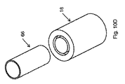
第2バルブ18は、液体燃料を燃料サプライ10から出すように構成されているだけである点を除いて、第1バルブ16と類似している。第2バルブ18はバルブ本体58および中央ポスト60を有し、これらは、実質的に、上述の第1バルブ18の内側の中央ポスト34と類似である。弾性シール62が第2バルブ18をシールし、流れチャネル64が内側ポスト60およびバルブ本体58の間に形成されている。ライナー28はシール状態でバルブ本体58に結合される。チューブ66の形状および寸法は、第2バルブ18中に空間68を入れ込み、弾性シール62を押圧し、第2バルブ18を開にして、流れチャネル64からの圧縮ガスにより強制的に燃料サプライ10から離れるようになすようなものになっている。
The
オプションとして、チューブ48または66が非標準サイズである。換言すれば、それらの寸法は、家庭やオフィスに通常散見される物品の寸法と異なり、これにより、シール部材38、44、または62が不用意に押圧されるのがより困難になるようになっている。代替的には、チューブ48または66は非円形または多角形(正規または非正規)の断面を伴うべきである。もちろん、中央ポスト34、40または60はこれらチューブを収容するために適合する形状を有しなければならない。
Optionally,
図7〜8に示される代替的な実施例において、弾性シール38、44および62はO−リング38’、44’、および62’、または、他のシール部材、例えば、ワッシャー、オーバーモールド弾性部分、弾性ボール、その他によって置き換えられる。中央ポスト34’および40’は、O−リングとともにシールを実現する環状のシール表面を実現するように変更される。この実施例の中央ポスト60’は外側リング61’を具備して、チューブ66が入り込んで第2バルブを開にする空間68’を実現する。
In the alternative embodiment shown in FIGS. 7-8, the
図5〜8や他の図面に説明されるように、バルブ16および18の、チューブ48および66に対面する、頂部表面は、係合面として終端してもよい。
As illustrated in FIGS. 5-8 and other figures, the top surface of
他の実施例において、第1バルブ16または第2バルブ18はいずれかのバルブの入口の近傍に配置されるシール部材70(例えばO−リング、シール面、ワッシャー、オーバーモールド弾性部分、弾性部分、またはその他)を具備してよい。例えば、図9(a)〜9(c)、および図10(a)〜10(c)に示されるように、シール部材70は第2バルブ18のバルブ本体58の内部に形成された溝中に配されたO−リングであってよい。シールはバルブ本体58、シール部材70、および中央ポスト60の間に実現される。空間68がバルブ本体58および中央ポスト60の間に形成される。この実施例において、チューブ66は中央ポスト60より大きな寸法、形状とされ、チューブ66が空間68中に入れ込まれると、これがO−リング70を外側に押して、図9(b)および9(c)に示されるように、チューブ66および中央ポスト60の間に流れチャネル64が許容されるようになる。図9(c)に示すようにチューブ66をさらに挿入すると、チューブ66がバルブ本体58の内部に確実に配される。チューブ66が、図9(b)に示すように、最初に空間68に挿入されると、要素間シールが、オプションとして、チューブ66およびバルブ本体58の間に形成される。図9(d)はバルブ18およびチューブ66の分解図を示す。
In other embodiments, the
図10(a)〜(d)の実施例は図9(a)〜(d)の実施例と類似である。ただし、O−リング70により実現されるシールに加えて第2のシールが弾性シール62および中央ポスト70によって実現される。ここで、チューブ66がO−リング70を脇に押すときに、バルブ18が図10(b)に示すように、シールされたままであり、この後、図10(c)に示すように、チューブ66が弾性シール62を押圧して流れ経路64を形成する。図10(d)は係合するチューブ66およびバルブ18の分解図を示す。
The embodiment shown in FIGS. 10A to 10D is similar to the embodiment shown in FIGS. However, in addition to the seal realized by the O-
図9(a)〜9(c)および図10(a)〜10(c)の手順はバルブ18について示されるけれども、同様の手順がチューブ48およびバルブ16の間の要素間シールを形成し、この後、バルブ16内で内部シールを開にするために適用できる。
Although the procedures of FIGS. 9 (a) -9 (c) and FIGS. 10 (a) -10 (c) are shown for
バルブ16またはバルブ18のいずれを閉止するための手順は上述の開手順と逆のプロセスに類似している。カートリッジ10は、まず、手作業で、あるいは、公知の排出機構を用いて自動的に、装置と係合解除され、いずれの圧縮シール(例えば、弾性シール38、44、および62、O−リング38’、44’、および62’、またはシール部材70)が貯蔵エネルギーを開放し、その当初の位置に復帰する。有利なことに、1つの具体的な実施例では、圧縮シール自体はそれ自体で排出機構として働く。この結果、カートリッジ10を排出するために外部のバネ力が不要であり、カートリッジ10内の空間を節約する。カートリッジが排出され、弾性シールが元の位置に復帰したのちに、中央ポストは、再度、弾性シールと係合して燃料カートリッジへの流れパスを閉じる。
The procedure for closing either
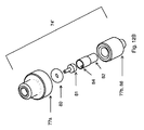
図11(a)〜(d)はこの発明の他の実施例を示す。図示のとおり、連結バルブ72は2つのバルブ要素74および76を有する。1つのバルブ要素は燃料サプライまたは装置(例えば、燃料電池、再充填装置、または、燃料電池システムに使用して好適な任意の他の装置)のいずれかと係合され、他のバルブ要素が燃料サプライまたは装置の他方と係合される。好ましくは、第1のバルブ要素74が装置と係合され、第2のバルブ要素76が好ましくは燃料サプライと係合される。図11(a)〜11(c)は第1のバルブ要素74および第2のバルブ要素76の連結と、その内部シールの開動作を示し、図11(d)は連結バルブ72の分解図を示す。
FIGS. 11A to 11D show another embodiment of the present invention. As shown, the
O−リング80は中央ポスト81との間で内部シールを形成し、これが、図示のとおり、頂部ハウジング77aと一体に形成される。内側チューブ82は選択的にO−リング80を押圧するために設けられ、これが、直径方向に対抗する一対の開口84を具備する。内側チューブ82は外側チューブ86内にちょうど入るような寸法および形状を伴う。チューブ82および86はその間に流路の一部をなす空間を形成する寸法および形状を伴う。内側チューブ82および外側チューブ86は底部76b内に配置され、スポークまたはウェブ(図示しない)によって連結されて相対的な位置を維持するようになっていてもよい。O−リング80が圧縮されていないとき、これが中央ポスト81に当接し、バルブ要素74をシールする。これが圧縮されるときには、バルブ要素74を通る流路が形成され、この流路がホースチューブ78から、圧縮されたO−リング80を通じて、チューブ82の空洞端部に至り、また開口84を通じ、また、内側チューブ82および外側チューブ86の間の空間を通じるようになっている。
The O-
第2のバルブ要素76もいくつかの部品を有し、これには頂部部分88aおよび底部部分88bを具備するハウジング88が含まれる。有利なことに、中央ポスト90は底部部分88bに固定的に結合され、O−リング92との間で内部シールを形成する環状の座面を具備する。底部部分88bはホースチューブ94も具備し、これが、O−リング92と流体的に結合する。バルブ要素74の外側チューブ86も中央ポスト90より大きく、これにより、その間を流体が流れる。
The
第1のバルブ要素74および第2のバルブ要素76の双方はチャネル98中のボルト96によって一体に結合される。さらに、O−リング(図示しない)が第1のバルブ要素74および第2のバルブ要素76の間に設けられ、2つのバルブ要素の間の要素間シールを容易に行えるようになっている。
Both the
図11(a)は、第1のバルブ要素74を、第2のバルブ要素76と非結合の状態で示す。燃料サプライを燃料電池に結合して燃料を燃料サプライから燃料電池に搬送させるために、第1のバルブ要素74からの外側チューブ86が第2のバルブ要素76の中の中央ポスト90の回りの空間100に、O−リング92に至るまで、挿入され、これを図11(b)に示す。図11(c)において、第1のバルブ要素74および第2のバルブ要素76における内部シールが開にされて流路101が形成される。第1のバルブ要素74内の内部シールは、中央ポスト90が内側チューブを押すときに、開となり、この中央ポスト90はつぎにO−リング80を押圧する。第2のバルブ要素76内の内部シールは、第1のバルブ要素74の外側チューブ86がO−リング92を押圧するときに、開となる。流路は、第2のバルブ要素において、ホースチューブ94から、圧縮されたO−リング92の回りを経て、中央ポスト90および第1のバルブ要素74の外側チューブ86の間の空間を通じて形成される。図11(c)に示すように、流路101は、第1のバルブ要素74および第2のバルブ要素76の内部の流路の組み合わせである。燃料は流路101を通じてホースチューブ78からホースチューブ94の方向または逆の方向のいずれにも流れて良い。
FIG. 11 (a) shows the
流路101を形成する際に、第1のバルブ要素74は第2のバルブ要素76と同時に開となってよく、あるいは、2つのバルブ要素が、それらの間の結合が完了した後に、時間を定めて逐次的な態様で開となってもよい。当業者に容易に理解できるように、いくつかの状況下で、カートリッジ10への流路を開にする前に、装置への流路を開とすると、有利であり、例えば、装置は、カートリッジ10に貯蔵されている燃料へのアクセスに先立って、流体または気体を受容する準備を確実にすることができる。このような順次的な開成は、単に、内側チューブ82、外側チューブ86、または中央ポスト90の長さを調整することで実現できる。例えば、第1のバルブ要素74が装置側にあるならば、外側チューブ86を短くし、内側チューブ82または中央ポスト90を短くしてよい。この場合、中央ポスト90が、外側チューブ86のO−リング92との係合に先立って、内側チューブ82を移動させる。代替的には、第2のバルブ要素が装置側にあるとすると、外側チューブ86が長くされて、内側チューブ82の中央ポスト90との係合に先立って、O−リング92を押圧するようになしてもよい。このような構成のいずれも、あるいは、組み合わせによって、一方のバルブ要素がその流路を開とするストロークが、他方のバルブ要素より長くなり、これにより、一方のバルブ要素が他方のバルブ要素より長い開手順を伴うようになる。
In forming the
他の例の第1のバルブ要素74’が図12(a)および12(b)に示される。ここでは、中央ポスト81がハウジング77aに締まりばめにより結合され、下方のハウジング部分77bが外側チューブ86に組みあわされる。内側チューブ82は下方ハウジング77b/外側チューブ86に対して若干の上下動が可能であり、O−リング80を押圧または押圧解除する。このバルブ要素74’の動作は図11(a)〜11(d)において説明された第1のバルブ要素74と類似である。
Another example first valve element 74 'is shown in FIGS. 12 (a) and 12 (b). Here, the
他の例の第1のバルブ要素74’’が図13(a)および(b)に示される。ここでは、中央ポスト81が、下方または外側に伸び、第1ハウジング部分77aに締まりばめにより結合されている。単一のチューブ82/86が内側チューブ82および外側チューブ86に置き換わり、O−リング80を押圧するように移動可能であり、これが上述のように、中央ポスト80とのシールを実現する。保持リング105は、チューブ82/86の外側リング103との干渉によって、バルブ要素74’’内にチューブ82/86を保持するようになっている。O−リング80が押圧されるとき、チューブ78から、中央ポスト81の小さな幹部の回りを経て、さらに、押圧されたO−リング80の回りを経て、チューブ82/86および中央ポスト81の間の空間に入る流路が形成される。図11(a)〜(d)に示されるように、チューブ82/86は、第2のバルブ要素76と結合されるときに、第2のバルブ要素76のO−リング92を、第1のバルブ要素74のO−リング80に加えて、押圧し、この押圧は先に検討したように、同時でも、逐次でもよい。
Another example
図14(a)〜(d)を参照すると、他の例のバルブ18が示される。この実施例では、中央ポスト60がバルブ本体58と一体に製造されているけれども、別々に製造され、先に検討され、また以下に図15(a)〜(b)に関連して説明されるようにバルブ本体58に固着されて良い。この例では、シール部材62は非平坦なワッシャーすなわちリップワッシャーであり、これが中央ポスト60との間のシールを実現する。図14(a)に最もよく示されるように、リップワッシャー62はバルブ本体58および保持部材107の間に保持される。ワッシャー62のシール部分は、図示のとおり、内側に配向されて中央ポスト60を押圧してシールを実現する。この実施例では、保持部材107および中央ポスト60の間に空間68が設けられ、これがチューブ66を収容する寸法および形状を伴う。また、チューブ66及び中央ポスト60の間に隙間が設けられ、これを通じて燃料が流れることが可能になっている。図14(b)に示すように、チューブ66は、それがリップワッシャー62に到達しさらに図14(c)に示すようにこれを超えるまで、空間68を通じてバルブ要素18中に挿入される。チューブ66が、一度、リップワッシャー62を超えて押し込まれると、図示のとおり流路が形成される。
Referring to FIGS. 14 (a) to 14 (d), another
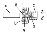
図15(a)〜(b)は図14(a)〜(b)のバルブ要素の変形例を示す。これら2つのバルブ要素は相互に類似する。ただし、ワッシャー62は平坦なワッシャーであり、中央ポスト60がバルブ本体58と別個に製造されている。さらに、バルブ本体58にはその内部に切り出しチャネル109が形成され、流路64の一部をなす。
15 (a) to 15 (b) show a modification of the valve element shown in FIGS. 14 (a) to 14 (b). These two valve elements are similar to each other. However, the
燃料サプライ10の変形例は本願の出願人の2007年8月22日の出願に係る米国仮出願60/957,362号に記述されている。’362出願の内容は参照してここに組み入れる。
A variation of
この明細書および例は例示としてのみ意図されており、この発明の本来の範囲および趣旨は以下の特許請求の範囲およびその均等物により示される。この発明の他の実施例が、ここで開示された、この発明の当該明細書およびその実施を考慮して、当業者には明らかであろう。さらに、1つの実施例の要素または特徴を他の実施例に採用できる。
なお、以下に、上述実施例の技術的な特徴を列挙する。
[技術的特徴1]
第1および第2のバルブ要素を有するバルブであって、
上記第1のバルブ要素は、バルブ本体、シール部材、および、当該バルブ本体に対して相対的に、実質的に固定であるように上記バルブ本体に固定されている中央ポストを有し、
上記シール部材は上記第1のバルブ要素の係合面から離れて位置し、上記中央ポストの回りに上記係合面との間に空間が設けられ、
上記空間は上記第2のバルブ要素からの空洞のチューブを収容する寸法及び形状を伴い、
上記空洞のチューブが上記第1のバルブ要素に押し込まれるときに、上記チューブが上記シール部材をシール位置から遠ざけて両バルブ要素を通じる流路を形成することを特徴とするバルブ。
[技術的特徴2]
上記中央ポストは上記バルブ本体と一体である技術的特徴1記載のバルブ。
[技術的特徴3]
上記流路は、上記チューブおよび上記中央ポストの間ならびに上記中央ポストおよび上記バルブ本体の間の経路を有する技術的特徴1記載のバルブ。
[技術的特徴4]
上記シール部材は、O−リング、弾性シール、シール面、ワッシャー、オーバーモールド弾性部分、平坦O−リング、非平坦O−リング、リップワッシャー、および弾性ボールからなるグループから選択される技術的特徴1記載のバルブ。
[技術的特徴5]
上記第1のバルブ要素は、上記バルブ本体に固着された第2の中央ポスト、および上記係合面から離れて位置する第2のシール部材を有し、
上記第2の中央ポストの回りに第2の空間が設けられ、
上記第2のバルブ要素は、上記第2の空間に入って両バルブ要素を通じる第2の流路を開にする寸法および形状を伴う第2のチューブを有する技術的特徴1記載のバルブ。
[技術的特徴6]
上記第2の中央ポストは上記中央ポストの回りに同芯的に位置決めされ、上記第2の空間は上記空間の回りに同芯的に位置決めされる技術的特徴5記載のバルブ。
[技術的特徴7]
上記流路及び上記第2の流路は逆方向である技術的特徴5記載のバルブ。
[技術的特徴8]
シール部材が上記バルブ本体と上記中央ポストとの間のシールを実現する技術的特徴1記載のバルブ。
[技術的特徴9]
上記第1のバルブ要素は、さらに、上記バルブ本体および上記中央ポストの間に第2のシール部材を有し、上記第2のバルブ要素の上記空洞のチューブが上記第2のシール部材を移動させて上記流路を形成する技術的特徴1または8記載のバルブ。
[技術的特徴10]
上記第2のバルブ要素はさらにバルブ本体、シール部材、および、当該バルブ本体に対して相対的に、実質的に固定であるようにバルブ本体に固定されている中央ポストを有する技術的特徴1記載のバルブ。
[技術的特徴11]
上記空洞のチューブが上記第2のバルブ要素の上記バルブ本体に対して移動可能であり、上記第2のバルブ要素の上記シール部材を押圧し、上記第2のバルブ要素を通じる流路を形成するようになす技術的特徴10記載のバルブ。
[技術的特徴12]
上記第2のバルブ要素はさらに第2の空洞のチューブを有し、上記第2の空洞のチューブが上記第2のバルブ要素の上記バルブ本体に対して移動可能であり、上記第2のバルブ要素の上記シール部材を押圧するようになす技術的特徴10記載のバルブ。
[技術的特徴13]
上記第2の空洞のチューブは上記空洞のチューブの回りに同芯的に位置決めされる技術的特徴12記載のバルブ。
[技術的特徴14]
上記空洞のチューブは上記第2のバルブ要素の上記バルブ本体に固定して結合される技術的特徴13記載のバルブ。
[技術的特徴15]
上記第1のバルブ要素は、燃料サプライ、または、燃料電池、燃料電池により給電される装置、再充填装置、および圧力調整器からなるグループから選択されたデバイスのいずれか一方に結合され、上記第2のバルブ要素は、燃料サプライまたは上記デバイスのいずれか他方に接続される技術的特徴1記載のバルブ。
[技術的特徴16]
上記シール部材は圧縮時に自己排出機構を伴う技術的特徴1記載のバルブ。
[技術的特徴17]
上記第1および第2のバルブ要素における上記流路は同時に開になる技術的特徴11記載のバルブ。
[技術的特徴18]
上記第1および第2のバルブ要素における上記流路は逐次的に開になる技術的特徴11記載のバルブ。
[技術的特徴19]
上記第1および上記第2のバルブ要素の間に要素間シールが形成される技術的特徴1記載のバルブ。
This specification and examples are intended as examples only, with the true scope and spirit of the invention being indicated by the following claims and their equivalents. Other embodiments of the invention will be apparent to those skilled in the art from consideration of the specification and practice of the invention disclosed herein. Further, elements or features of one embodiment can be employed in other embodiments.
The technical features of the above-described embodiments are listed below.
[Technical features 1]
A valve having first and second valve elements,
The first valve element has a valve body, a seal member, and a central post fixed to the valve body so as to be substantially fixed relative to the valve body;
The seal member is positioned away from the engagement surface of the first valve element, and a space is provided between the engagement surface and the center post;
The space is sized and shaped to accommodate a hollow tube from the second valve element,
When the hollow tube is pushed into the first valve element, the tube moves the seal member away from the sealing position to form a flow path through both valve elements.
[Technical feature 2]
The valve according to Technical Feature 1, wherein the central post is integral with the valve body.
[Technical feature 3]
The valve according to Technical Feature 1, wherein the flow path has a path between the tube and the central post and between the central post and the valve body.
[Technical feature 4]
The sealing member is a technical feature 1 selected from the group consisting of an O-ring, an elastic seal, a sealing surface, a washer, an overmold elastic portion, a flat O-ring, a non-flat O-ring, a lip washer, and an elastic ball. The valve described.
[Technical feature 5]
The first valve element has a second central post secured to the valve body, and a second seal member positioned away from the engagement surface;
A second space is provided around the second central post;
The valve according to Technical Feature 1, wherein the second valve element has a second tube with a size and shape that enters the second space and opens the second flow path through both valve elements.
[Technical feature 6]
The valve according to Technical Feature 5, wherein the second central post is positioned concentrically around the central post, and the second space is positioned concentrically around the space.
[Technical feature 7]
The valve according to technical feature 5, wherein the flow path and the second flow path are in opposite directions.
[Technical feature 8]
The valve according to Technical Feature 1, wherein a seal member realizes a seal between the valve body and the central post.
[Technical feature 9]
The first valve element further includes a second seal member between the valve body and the central post, and the hollow tube of the second valve element moves the second seal member. 9. The valve according to technical feature 1 or 8, wherein the flow path is formed.
[Technical feature 10]
Technical feature 1 wherein the second valve element further comprises a valve body, a sealing member and a central post fixed to the valve body so as to be substantially fixed relative to the valve body. Valve.
[Technical feature 11]
The hollow tube is movable with respect to the valve body of the second valve element and presses the seal member of the second valve element to form a flow path through the second valve element. The valve according to the
[Technical feature 12]
The second valve element further includes a second hollow tube, the second hollow tube is movable relative to the valve body of the second valve element, and the second valve element The valve according to the
[Technical feature 13]
13. The valve of
[Technical feature 14]
14. A valve according to
[Technical feature 15]
The first valve element is coupled to any one of a fuel supply or a device selected from the group consisting of a fuel cell, a fuel cell powered device, a refill device, and a pressure regulator, 2. Valve according to technical feature 1, wherein the two valve elements are connected to either the fuel supply or the other device.
[Technical feature 16]
The valve according to Technical Feature 1, wherein the seal member is accompanied by a self-discharge mechanism when compressed.
[Technical feature 17]
The valve according to the technical feature 11, wherein the flow paths in the first and second valve elements are simultaneously opened.
[Technical feature 18]
The valve according to the technical feature 11, wherein the flow paths in the first and second valve elements are sequentially opened.
[Technical feature 19]
The valve according to Technical Feature 1, wherein an inter-element seal is formed between the first and second valve elements.
Claims (15)
上記第1のバルブ要素は、バルブ本体、シール部材、および、当該バルブ本体に対して相対的に、実質的に不動であるように上記バルブ本体に固定されている中央ポストを有し、
上記シール部材は上記第1のバルブ要素の係合面から離れて位置し、上記係合面にギャップが設けられ、上記ギャップは上記中央ポストおよび上記バルブ本体の間に形成され、かつ、上記ギャップは、上記第1のバルブが閉位置にあるときに存在し、
上記ギャップは上記第2のバルブ要素からの空洞のチューブを収容する寸法及び形状を伴い、
上記空洞のチューブが上記ギャップの中に押し込まれるときに、上記チューブが上記シール部材をシール位置から遠ざけて両バルブ要素を通じる流路を形成することを特徴とするバルブ。 A valve having a first valve element and a second valve element,
The first valve element has a valve body, a seal member, and a central post fixed to the valve body so as to be substantially stationary relative to the valve body;
The seal member is located away from the engagement surface of the first valve element, the gap upward Kigakarigomen is provided, the gap is formed between the center post and the valve body, and the A gap exists when the first valve is in the closed position;
The gap is sized and shaped to accommodate a hollow tube from the second valve element,
When the hollow tube is pushed into the gap , the tube moves the seal member away from the sealing position to form a flow path through both valve elements.
上記第2の中央ポストの回りに第2の空間が設けられ、
上記第2のバルブ要素は、上記第2の空間に入って両バルブ要素を通じる第2の流路を開にする寸法および形状を伴う第2のチューブを有する請求項1記載のバルブ。 The first valve element has a second central post secured to the valve body, and a second seal member positioned away from the engagement surface;
A second space is provided around the second central post;
The valve according to claim 1, wherein the second valve element has a second tube with a size and shape that enters the second space and opens the second flow path through both valve elements.
Applications Claiming Priority (5)
| Application Number | Priority Date | Filing Date | Title |
|---|---|---|---|
| US95736207P | 2007-08-22 | 2007-08-22 | |
| US60/957,362 | 2007-08-22 | ||
| US1650807P | 2007-12-24 | 2007-12-24 | |
| US61/016,508 | 2007-12-24 | ||
| PCT/US2008/073868 WO2009026441A1 (en) | 2007-08-22 | 2008-08-21 | Non-interchangeable connecting valves for fuel cartridges |
Publications (3)
| Publication Number | Publication Date |
|---|---|
| JP2010536679A JP2010536679A (en) | 2010-12-02 |
| JP2010536679A5 JP2010536679A5 (en) | 2011-09-22 |
| JP5396391B2 true JP5396391B2 (en) | 2014-01-22 |
Family
ID=40378648
Family Applications (3)
| Application Number | Title | Priority Date | Filing Date |
|---|---|---|---|
| JP2010522025A Active JP5517936B2 (en) | 2007-08-22 | 2008-08-21 | Pressurized fuel cell cartridge |
| JP2010522026A Expired - Fee Related JP5396391B2 (en) | 2007-08-22 | 2008-08-21 | Non-interchangeable coupling valve for fuel cartridge |
| JP2014075028A Expired - Fee Related JP5883056B2 (en) | 2007-08-22 | 2014-04-01 | valve |
Family Applications Before (1)
| Application Number | Title | Priority Date | Filing Date |
|---|---|---|---|
| JP2010522025A Active JP5517936B2 (en) | 2007-08-22 | 2008-08-21 | Pressurized fuel cell cartridge |
Family Applications After (1)
| Application Number | Title | Priority Date | Filing Date |
|---|---|---|---|
| JP2014075028A Expired - Fee Related JP5883056B2 (en) | 2007-08-22 | 2014-04-01 | valve |
Country Status (11)
| Country | Link |
|---|---|
| US (3) | US8561965B2 (en) |
| EP (2) | EP2179210B1 (en) |
| JP (3) | JP5517936B2 (en) |
| KR (2) | KR101536734B1 (en) |
| CN (2) | CN101836311B (en) |
| BR (2) | BRPI0815702A8 (en) |
| CA (2) | CA2696769C (en) |
| MX (2) | MX2010001882A (en) |
| RU (1) | RU2468273C2 (en) |
| WO (2) | WO2009026441A1 (en) |
| ZA (2) | ZA201001446B (en) |
Families Citing this family (28)
| Publication number | Priority date | Publication date | Assignee | Title |
|---|---|---|---|---|
| DE60045248D1 (en) | 1999-09-20 | 2010-12-30 | Tivo Inc | CAPTION labeling |
| US9337501B2 (en) * | 2003-07-29 | 2016-05-10 | Intelligent Energy Limited | Hydrogen-generating fuel cell cartridges |
| US9016319B2 (en) * | 2007-08-22 | 2015-04-28 | Societe Bic | Relief valves for fuel cell systems |
| BRPI0815702A8 (en) * | 2007-08-22 | 2016-06-21 | SOCIéTé BIC | VALVE COMPRISING FIRST AND SECOND VALVE COMPONENTS |
| US8986404B2 (en) | 2009-11-03 | 2015-03-24 | Societe Bic | Gas generator with starter mechanism and catalyst shield |
| US8636826B2 (en) | 2009-11-03 | 2014-01-28 | Societe Bic | Hydrogen membrane separator |
| USD783815S1 (en) | 2009-12-09 | 2017-04-11 | General Electric Company | Male dual lumen bayonet connector |
| US10711930B2 (en) | 2009-12-09 | 2020-07-14 | Nordson Corporation | Releasable connection assembly |
| US9388929B2 (en) | 2009-12-09 | 2016-07-12 | Nordson Corporation | Male bayonet connector |
| JP5714028B2 (en) | 2009-12-23 | 2015-05-07 | ノードソン コーポレーションNordson Corporation | Fluid connector latch with profile retraction |
| CN102753876B (en) | 2009-12-23 | 2015-07-22 | 诺信公司 | Button latch with integrally molded cantilever springs |
| US20110232588A1 (en) * | 2010-03-26 | 2011-09-29 | Msp Corporation | Integrated system for vapor generation and thin film deposition |
| US8397784B2 (en) | 2010-08-31 | 2013-03-19 | Sanford, L.P. | Correction tape dispenser with variable clutch mechanism |
| US8578999B2 (en) | 2010-12-29 | 2013-11-12 | Sanford, L.P. | Variable clutch mechanism and correction tape dispenser with variable clutch mechanism |
| US8746313B2 (en) | 2010-12-29 | 2014-06-10 | Sanford, L.P. | Correction tape re-tensioning mechanism and correction tape dispenser comprising same |
| JP2014505347A (en) | 2011-02-11 | 2014-02-27 | ソシエテ ビック | Fuel cell system |
| JP5764007B2 (en) * | 2011-08-09 | 2015-08-12 | 大和製罐株式会社 | Liquid fuel cartridge for fuel cell |
| US8746316B2 (en) | 2011-12-30 | 2014-06-10 | Sanford, L.P. | Variable clutch mechanism and correction tape dispenser with variable clutch mechanism |
| US10193169B2 (en) | 2013-03-15 | 2019-01-29 | Intelligent Energy Limited | Fluidic interface module for a fuel cell system |
| US9577273B2 (en) | 2013-03-15 | 2017-02-21 | Intelligent Energy Limited | Fluidic interface module for a fuel cell system |
| US9680171B2 (en) | 2013-03-15 | 2017-06-13 | Intelligent Energy Limited | Methods for operating a fuel cell system |
| US9312550B2 (en) | 2013-03-15 | 2016-04-12 | Intelligent Energy Limited | Fluidic components suitable for fuel cell systems including pressure regulators and valves |
| IN2013MU02808A (en) | 2013-08-28 | 2015-07-03 | Indian Inst Technology | |
| US9979034B2 (en) * | 2013-10-23 | 2018-05-22 | Honeywell International Inc. | Fuel cell based power generator and fuel cartridge |
| US9876240B2 (en) | 2014-04-07 | 2018-01-23 | Intelligent Energy Limited | Multi-functional fuel cable |
| USD838366S1 (en) | 2016-10-31 | 2019-01-15 | Nordson Corporation | Blood pressure connector |
| KR102371012B1 (en) * | 2017-09-08 | 2022-03-04 | 현대자동차주식회사 | Fuel supplying valve for fuel cell system |
| US11117710B2 (en) * | 2017-12-04 | 2021-09-14 | Rapak, Llc | Valve assembly for bags |
Family Cites Families (46)
| Publication number | Priority date | Publication date | Assignee | Title |
|---|---|---|---|---|
| US465013A (en) | 1891-12-15 | Francois fernand bourdil | ||
| US2450446A (en) | 1946-12-12 | 1948-10-05 | Earl V Rupp | Oxygen warning device |
| US3010279A (en) * | 1957-04-08 | 1961-11-28 | Texaco Experiment Inc | Method of operating propulsion devices |
| NL101670C (en) | 1957-09-06 | |||
| US3544382A (en) * | 1967-07-08 | 1970-12-01 | Varta Ag | Fuel cell device for continuous operation |
| US3851852A (en) | 1972-08-16 | 1974-12-03 | Parker Hannifin Corp | Aerial refueling nozzle |
| US3973752A (en) | 1974-02-01 | 1976-08-10 | Uni-Mist, Inc. | Quick disconnect coupling for coaxial fluid lines |
| JPS5221420U (en) * | 1975-08-04 | 1977-02-15 | ||
| JPS54164125U (en) * | 1978-05-09 | 1979-11-17 | ||
| US5018352A (en) | 1983-11-28 | 1991-05-28 | Automotive Products Plc | Modular prefilled hydraulic control apparatus |
| US4726390A (en) | 1986-03-26 | 1988-02-23 | Waltec, Inc. | Hose bibb vacuum breaker |
| JPH0328235Y2 (en) * | 1988-09-20 | 1991-06-18 | ||
| JPH0323288U (en) * | 1989-07-17 | 1991-03-11 | ||
| JPH0380191U (en) * | 1989-12-07 | 1991-08-16 | ||
| US4997111A (en) * | 1989-12-12 | 1991-03-05 | Richard Lowers | Liquid dispensing apparatus |
| CN1080702A (en) * | 1992-07-03 | 1994-01-12 | 沈仲山 | The joint of quick joining water pipe |
| JPH06123391A (en) * | 1992-10-08 | 1994-05-06 | Kenichiro Takekoshi | Gas type quick coupling unit |
| US5293902A (en) | 1993-06-07 | 1994-03-15 | Tif Instruments, Inc. | Quick-disconnect fluid coupling |
| JP3002371U (en) * | 1994-03-25 | 1994-09-20 | 三島光産株式会社 | Fluid fitting |
| US5464042A (en) * | 1994-04-29 | 1995-11-07 | Aeroquip Corporation | Quick connect air-conditioning coupling |
| US5878798A (en) | 1997-02-28 | 1999-03-09 | Eastman Kodak Company | Valve system |
| US7022107B1 (en) * | 1999-09-22 | 2006-04-04 | Advanced Infusion, Inc. | Infusion pump with pressure regulator |
| US6708740B2 (en) | 2000-04-07 | 2004-03-23 | Kaj Wessberg | Method when tanking up using a tanking up valve |
| JP3760785B2 (en) * | 2001-03-21 | 2006-03-29 | 株式会社ジェイ・エム・エス | Rotary connector with valve |
| US6651955B2 (en) * | 2001-07-30 | 2003-11-25 | Hewlett-Packard Development Company, L.P. | Elastomeric valve, and methods |
| US6745998B2 (en) | 2001-08-10 | 2004-06-08 | Alaris Medical Systems, Inc. | Valved male luer |
| US7044441B2 (en) * | 2001-08-10 | 2006-05-16 | Cardinal Health 303, Inc. | Valved male luer connector having sequential valve timing |
| US7270907B2 (en) | 2002-01-08 | 2007-09-18 | Procter & Gamble Company | Fuel container and delivery apparatus for a liquid feed fuel cell system |
| JP2004263801A (en) * | 2003-03-03 | 2004-09-24 | Niimi Sangyo Kk | Charging device |
| US6962275B2 (en) * | 2003-05-19 | 2005-11-08 | Colder Products Company | Fluid coupling with disposable connector body |
| US7537024B2 (en) * | 2003-07-29 | 2009-05-26 | Societe Bic | Fuel cartridge with connecting valve |
| US8002853B2 (en) * | 2003-07-29 | 2011-08-23 | Societe Bic | Hydrogen-generating fuel cell cartridges |
| US7059582B2 (en) * | 2003-12-01 | 2006-06-13 | Societe Bic | Fuel cell supply having fuel compatible materials |
| RU2258167C1 (en) * | 2003-12-23 | 2005-08-10 | Лукьянов Владимир Ильич | Straightway stop valve |
| CN1910777B (en) * | 2004-01-20 | 2010-05-05 | 株式会社日立制作所 | Fuel container for fuel cell |
| KR100536200B1 (en) * | 2004-01-26 | 2005-12-12 | 삼성에스디아이 주식회사 | Fuel cell system |
| US7883815B2 (en) | 2004-06-25 | 2011-02-08 | Mitsubishi Pencil Co., Ltd. | Fuel-storing tank for fuel cell |
| JP2006093001A (en) * | 2004-09-27 | 2006-04-06 | Toshiba Corp | Coupler |
| JP2006221828A (en) | 2005-02-08 | 2006-08-24 | Sony Corp | Fuel cell system |
| US7727293B2 (en) * | 2005-02-25 | 2010-06-01 | SOCIéTé BIC | Hydrogen generating fuel cell cartridges |
| JP4764045B2 (en) * | 2005-03-29 | 2011-08-31 | 株式会社東芝 | coupler |
| JP2006309978A (en) * | 2005-03-30 | 2006-11-09 | Toshiba Corp | Liquid injection device for fuel cell |
| US7484530B2 (en) * | 2005-04-22 | 2009-02-03 | Parker-Hannifin Corporation | Dual purpose alignment and fluid coupling |
| JP2008266037A (en) * | 2007-04-16 | 2008-11-06 | Aquafairy Kk | Hydrogen generating apparatus |
| FR2919706B1 (en) * | 2007-07-30 | 2009-10-09 | Staubli Faverges Sca | RAPID CONNECTION ELEMENT AND RAPID CONNECTION COMPRISING SUCH A MEMBER |
| BRPI0815702A8 (en) * | 2007-08-22 | 2016-06-21 | SOCIéTé BIC | VALVE COMPRISING FIRST AND SECOND VALVE COMPONENTS |
-
2008
- 2008-08-21 BR BRPI0815702A patent/BRPI0815702A8/en not_active IP Right Cessation
- 2008-08-21 EP EP08798373.0A patent/EP2179210B1/en not_active Not-in-force
- 2008-08-21 WO PCT/US2008/073868 patent/WO2009026441A1/en active Application Filing
- 2008-08-21 JP JP2010522025A patent/JP5517936B2/en active Active
- 2008-08-21 CA CA2696769A patent/CA2696769C/en not_active Expired - Fee Related
- 2008-08-21 US US12/674,205 patent/US8561965B2/en active Active
- 2008-08-21 BR BRPI0815700A patent/BRPI0815700A8/en not_active IP Right Cessation
- 2008-08-21 KR KR1020107003780A patent/KR101536734B1/en active IP Right Grant
- 2008-08-21 CA CA2696766A patent/CA2696766A1/en not_active Abandoned
- 2008-08-21 CN CN200880112770.8A patent/CN101836311B/en not_active Expired - Fee Related
- 2008-08-21 WO PCT/US2008/073865 patent/WO2009026439A1/en active Application Filing
- 2008-08-21 EP EP08798370.6A patent/EP2183801B1/en not_active Not-in-force
- 2008-08-21 KR KR1020107003781A patent/KR101513121B1/en active IP Right Grant
- 2008-08-21 MX MX2010001882A patent/MX2010001882A/en unknown
- 2008-08-21 US US12/674,227 patent/US8932777B2/en not_active Expired - Fee Related
- 2008-08-21 CN CN2008801126103A patent/CN101836025B/en not_active Expired - Fee Related
- 2008-08-21 MX MX2010001883A patent/MX2010001883A/en unknown
- 2008-08-21 JP JP2010522026A patent/JP5396391B2/en not_active Expired - Fee Related
- 2008-08-21 RU RU2010105666/06A patent/RU2468273C2/en not_active IP Right Cessation
-
2010
- 2010-02-26 ZA ZA2010/01446A patent/ZA201001446B/en unknown
- 2010-02-26 ZA ZA2010/01445A patent/ZA201001445B/en unknown
-
2013
- 2013-09-20 US US14/032,966 patent/US8905373B2/en not_active Expired - Fee Related
-
2014
- 2014-04-01 JP JP2014075028A patent/JP5883056B2/en not_active Expired - Fee Related
Also Published As
Similar Documents
| Publication | Publication Date | Title |
|---|---|---|
| JP5396391B2 (en) | Non-interchangeable coupling valve for fuel cartridge | |
| KR101432142B1 (en) | Valves for fuel cartridges | |
| US8196894B2 (en) | Check valves for fuel cartridges | |
| JP2009514148A (en) | Fuel cartridge for a fuel cell in which fuel is stored outside the fuel liner | |
| US20050164065A1 (en) | Fuel cell system and fuel supply unit used therein | |
| US8235077B2 (en) | Device for refilling a fuel cartridge for a fuel cell | |
| RU2444817C2 (en) | Fuel barrel for fuel elements |
Legal Events
| Date | Code | Title | Description |
|---|---|---|---|
| A521 | Request for written amendment filed |
Free format text: JAPANESE INTERMEDIATE CODE: A523 Effective date: 20110808 |
|
| A621 | Written request for application examination |
Free format text: JAPANESE INTERMEDIATE CODE: A621 Effective date: 20110808 |
|
| A131 | Notification of reasons for refusal |
Free format text: JAPANESE INTERMEDIATE CODE: A131 Effective date: 20130205 |
|
| A601 | Written request for extension of time |
Free format text: JAPANESE INTERMEDIATE CODE: A601 Effective date: 20130424 |
|
| A602 | Written permission of extension of time |
Free format text: JAPANESE INTERMEDIATE CODE: A602 Effective date: 20130502 |
|
| A601 | Written request for extension of time |
Free format text: JAPANESE INTERMEDIATE CODE: A601 Effective date: 20130524 |
|
| A602 | Written permission of extension of time |
Free format text: JAPANESE INTERMEDIATE CODE: A602 Effective date: 20130531 |
|
| A601 | Written request for extension of time |
Free format text: JAPANESE INTERMEDIATE CODE: A601 Effective date: 20130618 |
|
| A602 | Written permission of extension of time |
Free format text: JAPANESE INTERMEDIATE CODE: A602 Effective date: 20130625 |
|
| A521 | Request for written amendment filed |
Free format text: JAPANESE INTERMEDIATE CODE: A523 Effective date: 20130803 |
|
| TRDD | Decision of grant or rejection written | ||
| A01 | Written decision to grant a patent or to grant a registration (utility model) |
Free format text: JAPANESE INTERMEDIATE CODE: A01 Effective date: 20131001 |
|
| A61 | First payment of annual fees (during grant procedure) |
Free format text: JAPANESE INTERMEDIATE CODE: A61 Effective date: 20131021 |
|
| R150 | Certificate of patent or registration of utility model |
Ref document number: 5396391 Country of ref document: JP Free format text: JAPANESE INTERMEDIATE CODE: R150 Free format text: JAPANESE INTERMEDIATE CODE: R150 |
|
| S111 | Request for change of ownership or part of ownership |
Free format text: JAPANESE INTERMEDIATE CODE: R313113 |
|
| R350 | Written notification of registration of transfer |
Free format text: JAPANESE INTERMEDIATE CODE: R350 |
|
| R250 | Receipt of annual fees |
Free format text: JAPANESE INTERMEDIATE CODE: R250 |
|
| R250 | Receipt of annual fees |
Free format text: JAPANESE INTERMEDIATE CODE: R250 |
|
| R250 | Receipt of annual fees |
Free format text: JAPANESE INTERMEDIATE CODE: R250 |
|
| R250 | Receipt of annual fees |
Free format text: JAPANESE INTERMEDIATE CODE: R250 |
|
| R250 | Receipt of annual fees |
Free format text: JAPANESE INTERMEDIATE CODE: R250 |
|
| R250 | Receipt of annual fees |
Free format text: JAPANESE INTERMEDIATE CODE: R250 |
|
| LAPS | Cancellation because of no payment of annual fees |