JP5390318B2 - Pouring tool with cap - Google Patents
Pouring tool with cap Download PDFInfo
- Publication number
- JP5390318B2 JP5390318B2 JP2009213410A JP2009213410A JP5390318B2 JP 5390318 B2 JP5390318 B2 JP 5390318B2 JP 2009213410 A JP2009213410 A JP 2009213410A JP 2009213410 A JP2009213410 A JP 2009213410A JP 5390318 B2 JP5390318 B2 JP 5390318B2
- Authority
- JP
- Japan
- Prior art keywords
- cap
- support ring
- top plate
- pouring
- tool
- Prior art date
- Legal status (The legal status is an assumption and is not a legal conclusion. Google has not performed a legal analysis and makes no representation as to the accuracy of the status listed.)
- Active
Links
Images


Description
本発明は、内容液の流路となる筒状部を有する注出具と該筒状部の開口を覆い、該筒状部に係合するキャップとからなるキャップ付注出具に関するものであり、より詳細には、容器を押圧することにより内容液の流通経路が形成されて内容液の取り出しが可能になるキャップ付注出具に関する。 The present invention relates to a pouring tool with a cap comprising a pouring tool having a cylindrical portion serving as a flow path for the content liquid and a cap that covers the opening of the tubular portion and engages with the tubular portion, and more More specifically, the present invention relates to a pouring tool with a cap that allows the content liquid to be taken out by forming a flow path of the content liquid by pressing the container.
洗剤等の用途に用いられるキャップは、一般に、容器口部に嵌合固定されるキャップ本体及びキャップ本体頂板部に形成された開口を覆う上蓋から成っており、このようなキャップが適用された容器が横倒しになった場合、上蓋とキャップ本体頂板部で形成される空間に内容液が流出して、キャップ本体及び上蓋で区画されるキャップ内空間が内容液で汚染されたり、或いは液漏れが発生したりするおそれがある。
また、蓋を有する注出具付パウチ容器では、容器を支える部分がないため、蓋を開けた時点で不用意にパウチ容器の胴部を押圧して内容液が外部にでてしまうことがある。
このような問題を解決するものとして、容器を押圧(スクイズ)することにより、開放されるスリットから成る弁機構を備えたキャップも提案されている(特許文献1)。
また、内容液取出し後、容器を押圧することにより負圧になった容器内に空気が逆流することを防止するために、弁機構を採用することも提案されている(特許文献2,3)。
Caps used for applications such as detergents generally consist of a cap body fitted and fixed to the container mouth and an upper lid covering the opening formed in the top plate of the cap body, and a container to which such a cap is applied. Lies on the side of the cap and the cap body top plate, the contents liquid flows out, and the space inside the cap defined by the cap body and the top lid is contaminated with the contents liquid, or liquid leakage occurs. There is a risk of doing so.
Moreover, in the pouch container with a pouring tool having a lid, since there is no portion that supports the container, the content liquid may come out by inadvertently pressing the trunk of the pouch container when the lid is opened.
As a solution to such a problem, a cap having a valve mechanism including a slit that is opened by pressing (squeezing) a container has also been proposed (Patent Document 1).
In addition, it has also been proposed to employ a valve mechanism in order to prevent air from flowing back into the container that has become negative pressure by pressing the container after the content liquid is taken out (
しかしながら、上述した先行技術で提案されるキャップは、キャップ或いは容器とは別途形成されたライナー材や或いは弾性部材を組み合わせる必要があり、機構が複雑であることから成形性及び生産性の点で十分満足するものではない。
従って本発明の目的は、簡単な構成でキャップ、容器口部をそれぞれ一体的に成形することが可能であり、成形性及び生産性に優れていると共に、確実な弁機構により内容液の注出及び止栓が可能なキャップ付注出具を提供することである。
However, the cap proposed in the above-described prior art requires a combination of a liner material or an elastic member formed separately from the cap or container, and the mechanism is complicated, so that it is sufficient in terms of formability and productivity. Not satisfied.
Accordingly, an object of the present invention is to form the cap and the container mouth part integrally with a simple structure, which is excellent in moldability and productivity, and dispenses the content liquid by a reliable valve mechanism. And providing a pouring tool with a cap that can be stopped.
本発明によれば、内容液の流路となる筒状部を有する注出具と該筒状部の開口を覆い、該筒状部に係合するキャップとからなるキャップ付注出具であって、前記キャップは、口部に係合固定されるキャップ本体及び該キャップ本体に脱着可能に係合される上蓋から成り、前記キャップ本体は、スカート部及び頂板部から成り、該頂板部内面には口部内側面と密着するインナーリング、該インナーリングよりも内側に内容液注出用開口、及び該内容液注出用開口よりも中心側の頂板部内面にサポートリングが形成されており、前記口部の内側面には、内方に突出し且つ先端がサポートリング外面に当接する環状フランジが形成されており、容器内を陽圧にすることにより、キャップ本体頂板部がドーム状に変形し、サポートリングが該変形に追従して半径方向内方に変形して内容液の注出が可能になることを特徴とするキャップ付注出具が提供される。 According to the present invention, there is provided a pouring tool with a cap comprising a pouring tool having a cylindrical portion serving as a flow passage for the content liquid and a cap that covers the opening of the tubular portion and engages with the tubular portion, The cap includes a cap body engaged with and fixed to the mouth portion and an upper lid detachably engaged with the cap body. The cap body includes a skirt portion and a top plate portion. An inner ring that is in intimate contact with the inner side surface of the portion, an opening for discharging the content liquid inside the inner ring, and a support ring formed on the inner surface of the top plate portion closer to the center than the opening for discharging the content liquid, An annular flange that protrudes inward and whose tip abuts on the outer surface of the support ring is formed on the inner surface of the cap. By making the inside of the container positive pressure, the cap body top plate is deformed into a dome shape, and the support ring Added to the deformation Cap annotation Daegu is provided, characterized in that it enables pouring of liquid contents deformed radially inward by.
本発明のキャップ付注出具においては、
1.サポートリングの内面に、頂板部内面とサポートリング内面に連なるリブが形成されていること、
2.頂板部のサポートリングの付け根外側に、薄肉部が形成されていること、
3.注出具が、筒状部の外面の下方部分にパウチとの溶着部を有していること、
が好適である。
In the pouring tool with a cap of the present invention,
1. Ribs connected to the inner surface of the support ring and the inner surface of the top plate portion and the inner surface of the support ring are formed.
2. A thin-walled part is formed outside the base of the support ring of the top plate part,
3. The dispensing tool has a welded portion with a pouch in the lower part of the outer surface of the tubular portion;
Is preferred.
本発明のキャップ付注出具は、キャップと注出具との組合せにおいてキャップを一体成形することが可能であり、従来必須とされたライナー材や弾性部材を要することがなく、成形性及び生産性に優れている。
また簡単な機構で確実に内容液の注出及び閉栓が可能である。
本発明のキャップ付注出具に用いる容器は、パウチやスクイズ可能な樹脂ボトルを用いることができる。
The pouring tool with a cap according to the present invention can integrally form a cap in a combination of the cap and the pouring tool, and does not require a liner material and an elastic member, which have been conventionally required, so that the moldability and productivity are improved. Are better.
In addition, it is possible to reliably pour out and close the contents with a simple mechanism.
The container used for the pouring tool with a cap of the present invention can be a pouch or a resin bottle that can be squeezed.
本発明のキャップ付注出具を、図1乃至図5に示したキャップ付注出具に適用した場合で詳細に説明する。
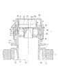
全体を1で示すキャップ付注出具は、概略的に言って、パウチ2に溶着固定される注出具10、注出具10に嵌合固定されるキャップ本体30、キャップ本体30の頂板部を覆い、キャップ本体とヒンジ50により一体的に成形されて成る上蓋40から成っている。
A case where the pouring tool with a cap of the present invention is applied to the pouring tool with a cap shown in FIGS. 1 to 5 will be described in detail.
The pouring tool with a cap denoted as a whole by 1 generally covers the
注出具10は、概略的に言って、内容液を注出するための筒状部11及び筒状部11の外面の下方部分に形成されたパウチを溶着固定する溶着部12から成っている。
筒状部11は、内部に注出用貫通路13を有しており、この注出用貫通路13は、これを介してパウチ2の内容液の注ぎ出しが行われる。
また、筒状部11の外面には、上記溶着部12の上方に上部フランジ14が形成されている。この上部フランジ14は、このキャップ付注出具或いはこのキャップ付注出具がセットされたパウチ2を搬送する際に把持するためのものである。 筒状部11の外面には、上記上部フランジ14の上方部分に、後述するキャップ本体を嵌合固定するための係合突起15が形成されている。筒状部11の内面には、半径方向内方に突出する環状フランジ16が形成されている。この環状フランジ16の先端は、後述するキャップ本体のサポートリングの下方外面と密着する。
Generally speaking, the
The
Further, an
筒状部11の外面には、上部フランジ14よりやや下方に下部フランジ17が形成され、下部フランジの下方に溶着部12が形成されており、溶着部12においてパウチ2に溶着固定される。パウチ2が溶着される溶着部12には、横リブ19が複数(図3では3個)形成されている。この横リブ19によりパウチと均一な溶着が可能となり接着強度の向上が図られる。また溶着部12には、下面から上方に延びる凹部20が筒状部の両側に設けられている。
A
キャップ本体30は、頂板部31及びスカート部32から成り、スカート部32の内面には、上述した注出具10の係合突起15と係合してキャップ本体を固定するための係合用突起33が形成されており、また頂板部31の内側にはインナーリング34が形成されており、これらによってキャップ本体は注出具に嵌合固定されている。
また頂板部31の内側には、インナーリング34よりも内側に内容液注出用開口35が形成されており、更に内容液注出用開口35よりも中心側の頂板部内面にサポートリング36が形成されている。このサポートリング36で区画される頂板部31aの肉厚は、他の部分31bに比して薄肉に形成されていると共に、サポートリングの付け根外周側の頂板部31内面には、環状凹部37が形成され、頂板部が薄肉化されている。更に、サポートリング36の内面側には、頂板部31a内面とサポートリング36内面に連なるリブ38が3つ形成されている。このリブ38は、頂板部から下方に行くに従ってサポートリング36内面からの突出量が少なくなるテーパ状に形成されている。
更に頂板部31の外側には、内容液注出開口35を取り囲むようにして、周状突起39が設けられており、これにより、内容液の注ぎ出しに際して、この周状突起39が案内となって、液の注ぎ出しをスムーズに行うことができる。
The
Further, a content
Further, a
上蓋40の内面には、これを閉じた時に、前記周状突起39の内周面に密着し得るような周状下方突起41が形成されており、これにより、上蓋40を閉じると、内容液注出開口35が完全に閉じられ、良好な密封性が確保される。
尚、図1及び図2に示されるように、開口予定部11を取り囲むように設けられている周状突起39は、キャップ本体30と上蓋40とのヒンジ連結部50と反対側の半周部分39aは背が高く、且つヒンジ連結部50側の半周部分39bは背が低く形成されていることが好ましい。これにより、上蓋40を閉じた時、上蓋40に設けられている周状下方突起41がスムーズに周状突起39内に入り込み、上蓋40の旋回が妨げられることがなく、また、内容液の注ぎ出しはヒンジ連結部50とは反対側から行われるため、周状突起39の注ぎ出し用案内としての機能が損なわれることもない。
A circumferential
As shown in FIGS. 1 and 2, the
図1に示すように、本発明のキャップ付注出具においては、注出具10の環状フランジ16の先端が、サポートリング36の下方外面と密着しているため、上蓋40を開放しても、この状態では内容液はパウチ2、注出具10、キャップ本体30のサポートリング36、及びサポートリング36で区画されるキャップ本体30の頂板部31で形成される空間内にとどまっている。
本発明においては、パウチ2を押圧して、かかる空間内の圧力を陽圧にすることにより、サポートリング36で区画された薄肉の頂板部31aは、ドーム状に変形し、この変形に追従してサポートリング36の下方は半径方向内方に撓むように変形する。特に図1及び図2に示す具体例においては、環状凹部37及びリブ38の存在と相俟って、頂板部31aの変形に追従した変形をサポートリング36に生じさせやすくなっている。
このように、サポートリング36が内側に撓むことにより、図2に示すように、注出具10に形成された環状フランジ16の先端とサポートリング36外面の間に空隙3が生じ、この空隙3を通って、内容液注出開口内容液35への流出が可能となる。またパウチの押圧を中止すれば、サポートリング36は元の形状に戻るので、再び環状フランジ16の先端とサポートリング36外面が密着して、液密性が確保される。
As shown in FIG. 1, in the pouring tool with a cap of the present invention, the tip of the
In the present invention, by pressing the
Thus, as shown in FIG. 2, the
本発明のキャップ付注出具は、上述したパウチ等に適用される注出具に限定されず、スクイズ可能な樹脂ボトルの口部に係止される注出具としても同様に適用できる。
すなわち、上述した具体例における注出具の部分が容器口部に該当し、この容器口部の内側面に環状フランジを形成し、上述したキャップ本体を取り付けることにより、同様の作用効果を奏することができる。また容器としては、押圧により容易に変形可能な所謂スクイズボトルに好適に使用できる。
また図1乃至図5に示した具体例においては、上蓋がキャップ本体にヒンジ連結されたヒンジキャップであったが、これに限定されるものではなく、キャップ本体に螺子係合や或いは嵌合固定により着脱可能なものであってもよい。
また図1乃至図5に示した具体例においては、注出用開口がキャップ本体頂板部に予め形成されていたが、これに限定されるものではなく、キャップ本体頂板部外面側に注出用開口を区画するスコア及びスコア破断用のタブを形成し、内容液の使用開始に当たって注出用開口を形成するものであっても勿論よい。また予め注出用開口を形成しておく場合には、アルミニウム積層体等のシール材で注出用開口をシールしておくことが望ましい。
The pouring tool with a cap of the present invention is not limited to the pouring tool applied to the above-described pouch or the like, and can be similarly applied as an pouring tool that is locked to the mouth of a squeezeable resin bottle.
That is, the portion of the dispensing tool in the specific example described above corresponds to the container mouth, and an annular flange is formed on the inner surface of the container mouth, and the same effect can be achieved by attaching the cap body described above. it can. Moreover, as a container, it can use suitably for what is called a squeeze bottle which can be changed easily by press.
In the specific examples shown in FIGS. 1 to 5, the upper lid is a hinge cap hinged to the cap body. However, the present invention is not limited to this, and the cap body is screw-engaged or fitted and fixed. May be removable.
Further, in the specific examples shown in FIGS. 1 to 5, the dispensing opening is formed in the cap body top plate portion in advance, but the invention is not limited to this, and the dispensing opening is provided on the outer surface side of the cap body top plate portion. Of course, it is also possible to form a score for dividing the opening and a tab for breaking the score, and to form an opening for dispensing when the use of the content liquid is started. In addition, when the extraction opening is formed in advance, it is desirable to seal the extraction opening with a sealing material such as an aluminum laminate.
更に頂板部の変形に追従するサポートリングの変形をより容易に行わせるためにサポートリング内側に形成される、頂板部及びサポートリング内側に連なるリブは、図1乃至図5に示した具体例のように、下方に行くに従ってサポートリング36内面からの突出量が減少するものであることが、サポートリングの内側への変形を容易にすると共に、成形性の点で好ましい。またリブの縦方向長さ、突出量、肉厚、或いは個数は、サポートリングの内径、肉厚、或いは縦方向長さ等によって一概に規定することはできないが、頂板部の変形を損なうことなく、サポートリングの変形を補助するという点からは、リブは薄肉で、リブの縦方向長さはサポートリングの薄肉頂板部31aから環状フランジ上端までの長さの15%乃至100%の長さを有するものであることが望ましい。
Further, the ribs connected to the inside of the support plate and the support ring, which are formed inside the support ring in order to make the deformation of the support ring following the deformation of the top plate easier, are of the example shown in FIGS. As described above, it is preferable that the amount of protrusion from the inner surface of the
本発明のキャップ付注出具は、例えば図1乃至図5に示した注出具付きパウチの場合、注出具、キャップ本体及び上蓋の各部材を、それぞれ射出成形や押出成形等の従来公知の成形法により一体的に成形し、これらをパウチに組み付けることにより容易に成形することができる。
またスクイズ可能な樹脂ボトルの場合は、上述と同様の方法で成形されたキャップ付注出具を樹脂ボトルの口部に係止することにより容易に組み付けることができる。
また本発明のキャップ付注出具を構成可能な樹脂は、従来キャップ、注出具、容器等に使用されている溶融成形可能な熱可塑性樹脂を用いることができ、これに限定されないが、ポリエチレン、ポリプロピレン等を好適に使用することができる。
For example, in the case of the pouch with a pour tool shown in FIGS. 1 to 5, the pour tool with the cap of the present invention is a conventionally known molding method such as injection molding or extrusion molding for each of the pour tool, the cap body and the upper lid. Can be molded easily by molding them together and assembling them on the pouch.
Further, in the case of a resin bottle that can be squeezed, it can be easily assembled by locking a pouring tool with a cap formed by the same method as described above to the mouth of the resin bottle.
Further, the resin capable of constituting the pouring tool with a cap according to the present invention may be a melt-moldable thermoplastic resin conventionally used for caps, pouring tools, containers, etc., but is not limited thereto, but is not limited to polyethylene, polypropylene. Etc. can be used suitably.
本発明においては、容器の押圧により容易に内容液の流出路を形成することが可能な弁機構を提供することが可能であり、簡単な構成で生産性及び経済性よく成形することができ、特に洗剤等の液体に使用される、汎用の注出具付きパウチ、或いはキャップ付き容器として好適に使用することができる。 In the present invention, it is possible to provide a valve mechanism that can easily form the outflow passage of the content liquid by pressing the container, can be molded with a simple configuration with good productivity and economy, In particular, it can be suitably used as a general-purpose pouch with a pouring tool or a cap-equipped container used for liquids such as detergents.
1 キャップ付注出具、2 パウチ、3 空隙、10 注出具、11 筒状部、12 溶着部、13 注出用貫通路、14 上部フランジ、15 係合突起、16 環状フランジ、17 下部フランジ、19 横リブ、20 凹部、30 キャップ本体、31 頂板部、32 スカート部、33 係合用突起、34 インナーリング、35 内容液注出用開口、36 サポートリング、37 環状凹部、38 リブ、39 周状突起、40 上蓋、41 周状下方突起、50 ヒンジ連結部。
DESCRIPTION OF
Claims (4)
前記キャップ本体は、スカート部及び頂板部から成り、該頂板部内面には筒状部内側面と密着するインナーリング、該インナーリングよりも内側に内容液注出用開口、及び該内容液注出用開口よりも中心側の頂板部内面にサポートリングが形成されており、
前記筒状部の内側面には、内方に突出し且つ先端がサポートリング外面に当接する環状フランジが形成されており、
容器内を陽圧にすることにより、キャップ本体頂板部がドーム状に変形し、サポートリングが該変形に追従して半径方向内方に変形して内容液の注出が可能になることを特徴とするキャップ付注出具。 A pouring tool with a cap comprising a pouring tool having a cylindrical portion serving as a flow path for the content liquid and a cap that covers the opening of the cylindrical portion and engages with the cylindrical portion, wherein the cap is tubular. A cap body engaged with and fixed to the part, and an upper lid removably engaged with the cap body,
The cap body is composed of a skirt portion and a top plate portion, an inner ring that is in close contact with the inner surface of the cylindrical portion on the inner surface of the top plate portion, an opening for pouring the content liquid inside the inner ring, and for pouring the content liquid A support ring is formed on the inner surface of the top plate part closer to the center than the opening.
An annular flange is formed on the inner side surface of the cylindrical part so as to protrude inward and the tip abuts against the outer surface of the support ring.
By making the inside of the container positive pressure, the cap body top plate part is deformed into a dome shape, and the support ring is deformed inward in the radial direction following the deformation, allowing the content liquid to be poured out. An extraction tool with a cap.
Priority Applications (1)
| Application Number | Priority Date | Filing Date | Title |
|---|---|---|---|
| JP2009213410A JP5390318B2 (en) | 2009-09-15 | 2009-09-15 | Pouring tool with cap |
Applications Claiming Priority (1)
| Application Number | Priority Date | Filing Date | Title |
|---|---|---|---|
| JP2009213410A JP5390318B2 (en) | 2009-09-15 | 2009-09-15 | Pouring tool with cap |
Publications (2)
| Publication Number | Publication Date |
|---|---|
| JP2011063277A JP2011063277A (en) | 2011-03-31 |
| JP5390318B2 true JP5390318B2 (en) | 2014-01-15 |
Family
ID=43949961
Family Applications (1)
| Application Number | Title | Priority Date | Filing Date |
|---|---|---|---|
| JP2009213410A Active JP5390318B2 (en) | 2009-09-15 | 2009-09-15 | Pouring tool with cap |
Country Status (1)
| Country | Link |
|---|---|
| JP (1) | JP5390318B2 (en) |
Families Citing this family (5)
| Publication number | Priority date | Publication date | Assignee | Title |
|---|---|---|---|---|
| JP5804849B2 (en) * | 2011-08-30 | 2015-11-04 | 日本クロージャー株式会社 | Pouring tool with check valve and cap thereof |
| JP6068968B2 (en) * | 2012-12-12 | 2017-01-25 | 押尾産業株式会社 | cap |
| JP6375598B2 (en) * | 2013-07-26 | 2018-08-22 | 東洋製罐株式会社 | Cleaning nozzle, cleaning method, and filling cleaning method for cleaning container mouth of container with cap |
| JP2016172595A (en) * | 2016-07-06 | 2016-09-29 | 押尾産業株式会社 | Spouting tool |
| JP6330023B2 (en) * | 2016-12-26 | 2018-05-23 | 押尾産業株式会社 | cap |
Family Cites Families (5)
| Publication number | Priority date | Publication date | Assignee | Title |
|---|---|---|---|---|
| JPS4532532Y1 (en) * | 1968-03-14 | 1970-12-12 | ||
| JP3410551B2 (en) * | 1994-07-14 | 2003-05-26 | 日本クラウンコルク株式会社 | Squeeze bottle cap |
| JP4043682B2 (en) * | 2000-02-29 | 2008-02-06 | 株式会社吉野工業所 | Tube container |
| JP4725991B2 (en) * | 2004-08-31 | 2011-07-13 | 株式会社吉野工業所 | Flexible container |
| JP5239521B2 (en) * | 2007-06-04 | 2013-07-17 | 大日本印刷株式会社 | Pouch container |
-
2009
- 2009-09-15 JP JP2009213410A patent/JP5390318B2/en active Active
Also Published As
| Publication number | Publication date |
|---|---|
| JP2011063277A (en) | 2011-03-31 |
Similar Documents
| Publication | Publication Date | Title |
|---|---|---|
| JP5390318B2 (en) | Pouring tool with cap | |
| WO2014084264A1 (en) | Refilling container stopper | |
| US20170267425A1 (en) | Anti-glug device for liquid containers and pour spouts | |
| JP5713345B2 (en) | Delamination container | |
| JP2018062351A (en) | Spout for refilling container and refilling container with spout | |
| JP2007176577A (en) | Pouring cap | |
| JP4954695B2 (en) | Refill container | |
| AU2014331018B2 (en) | Measuring cap | |
| JP5362440B2 (en) | Hinge cap | |
| US11377271B2 (en) | Plastic closure part with severable membrane | |
| CN110267882B (en) | Closing unit | |
| JP2014080218A (en) | Plug member for refill vessel | |
| JP5270613B2 (en) | Spouted container and stopper | |
| WO2017022736A1 (en) | Container pouring spout sealing structure | |
| JP6083855B2 (en) | Refill container stopper | |
| KR20170097600A (en) | Container | |
| JP6501698B2 (en) | Double container cap | |
| JP7391478B2 (en) | Container cap and method for manufacturing a container cap | |
| JP7345968B2 (en) | container cap | |
| JP5711976B2 (en) | Synthetic resin caps and containers with caps | |
| JP4790434B2 (en) | Hinge cap | |
| JP2022055008A (en) | Plastic molded body | |
| JP6796469B2 (en) | Noter | |
| JP2023140961A (en) | Plastic molding body | |
| JP2023016766A (en) | Method of manufacturing pour-out plug, pour-out plug and package container |
Legal Events
| Date | Code | Title | Description |
|---|---|---|---|
| A625 | Written request for application examination (by other person) |
Free format text: JAPANESE INTERMEDIATE CODE: A625 Effective date: 20120820 |
|
| A977 | Report on retrieval |
Free format text: JAPANESE INTERMEDIATE CODE: A971007 Effective date: 20130805 |
|
| TRDD | Decision of grant or rejection written | ||
| A01 | Written decision to grant a patent or to grant a registration (utility model) |
Free format text: JAPANESE INTERMEDIATE CODE: A01 Effective date: 20131001 |
|
| A61 | First payment of annual fees (during grant procedure) |
Free format text: JAPANESE INTERMEDIATE CODE: A61 Effective date: 20131010 |
|
| R150 | Certificate of patent or registration of utility model |
Ref document number: 5390318 Country of ref document: JP Free format text: JAPANESE INTERMEDIATE CODE: R150 Free format text: JAPANESE INTERMEDIATE CODE: R150 |