JP5390150B2 - Auxiliary tool and endoscope system - Google Patents
Auxiliary tool and endoscope system Download PDFInfo
- Publication number
- JP5390150B2 JP5390150B2 JP2008244379A JP2008244379A JP5390150B2 JP 5390150 B2 JP5390150 B2 JP 5390150B2 JP 2008244379 A JP2008244379 A JP 2008244379A JP 2008244379 A JP2008244379 A JP 2008244379A JP 5390150 B2 JP5390150 B2 JP 5390150B2
- Authority
- JP
- Japan
- Prior art keywords
- endoscope
- insertion portion
- auxiliary tool
- conduit
- forceps
- Prior art date
- Legal status (The legal status is an assumption and is not a legal conclusion. Google has not performed a legal analysis and makes no representation as to the accuracy of the status listed.)
- Expired - Fee Related
Links
Images


Classifications
-
- A—HUMAN NECESSITIES
- A61—MEDICAL OR VETERINARY SCIENCE; HYGIENE
- A61B—DIAGNOSIS; SURGERY; IDENTIFICATION
- A61B1/00—Instruments for performing medical examinations of the interior of cavities or tubes of the body by visual or photographical inspection, e.g. endoscopes; Illuminating arrangements therefor
- A61B1/00064—Constructional details of the endoscope body
- A61B1/00105—Constructional details of the endoscope body characterised by modular construction
-
- A—HUMAN NECESSITIES
- A61—MEDICAL OR VETERINARY SCIENCE; HYGIENE
- A61B—DIAGNOSIS; SURGERY; IDENTIFICATION
- A61B1/00—Instruments for performing medical examinations of the interior of cavities or tubes of the body by visual or photographical inspection, e.g. endoscopes; Illuminating arrangements therefor
- A61B1/00131—Accessories for endoscopes
- A61B1/0014—Fastening element for attaching accessories to the outside of an endoscope, e.g. clips, clamps or bands
-
- A—HUMAN NECESSITIES
- A61—MEDICAL OR VETERINARY SCIENCE; HYGIENE
- A61B—DIAGNOSIS; SURGERY; IDENTIFICATION
- A61B1/00—Instruments for performing medical examinations of the interior of cavities or tubes of the body by visual or photographical inspection, e.g. endoscopes; Illuminating arrangements therefor
- A61B1/012—Instruments for performing medical examinations of the interior of cavities or tubes of the body by visual or photographical inspection, e.g. endoscopes; Illuminating arrangements therefor characterised by internal passages or accessories therefor
-
- A—HUMAN NECESSITIES
- A61—MEDICAL OR VETERINARY SCIENCE; HYGIENE
- A61B—DIAGNOSIS; SURGERY; IDENTIFICATION
- A61B1/00—Instruments for performing medical examinations of the interior of cavities or tubes of the body by visual or photographical inspection, e.g. endoscopes; Illuminating arrangements therefor
- A61B1/233—Instruments for performing medical examinations of the interior of cavities or tubes of the body by visual or photographical inspection, e.g. endoscopes; Illuminating arrangements therefor for the nose, i.e. nasoscopes, e.g. testing of patency of Eustachian tubes
Description
本発明は、経鼻内視鏡の機能を補助する補助具、及びこの補助具と経鼻内視鏡とからなる内視鏡システムに関する。 The present invention relates to an auxiliary tool that assists the function of a transnasal endoscope, and an endoscope system that includes the auxiliary tool and a transnasal endoscope.
可撓管状に形成された挿入部を外鼻孔から挿入して被検者の体腔内の検査を行う、いわゆる経鼻内視鏡が知られている(特許文献1、特許文献2)。経鼻内視鏡は、挿入部が舌根に触れることなく食道に入っていくので、挿入部を口から挿入する経口内視鏡に比べて咽頭反射が起き難く、ほとんど吐き気を催さないなど被検者に与える負荷が低い。また、経鼻内視鏡には、口呼吸が可能になる、経口内視鏡検査に比べて麻酔薬も少量でよく、検査中に被検者と会話をすることができるなどの利点もあるため、近年、需要が増加している。 A so-called nasal endoscope is known in which an insertion portion formed in a flexible tubular shape is inserted from an outer nostril to inspect a body cavity of a subject (Patent Documents 1 and 2). Transnasal endoscopes enter the esophagus without touching the tongue base, so pharyngeal reflexes are less likely to occur than oral endoscopes where the insertion part is inserted through the mouth, and there is little nausea. The load on the person is low. Transnasal endoscopes also have the advantage that mouth breathing is possible, anesthetics are smaller than oral endoscopy, and conversation with the subject can be performed during the examination. Therefore, demand has increased in recent years.
経鼻内視鏡は、経口内視鏡と同様に構成されており、挿入部の内部空間には、各種の処置具を挿通するための鉗子管路、空気や水を観察光学系の先端面(観察窓)や体腔内に送り込むための送気・送水用管路、及び光源装置から供給される光を案内して先端部から照明光として照射させるためのライトガイドなどが収容されている。
経鼻内視鏡は、外鼻孔から中鼻道(下鼻道)へと狭く曲がりくねった挿入経路を通過させるため、経口内視鏡の挿入部の径が9mm前後であるのに対し、6mm前後と挿入部の径が経口内視鏡よりも細くなっている。このため、経鼻内視鏡には、挿入部内に設けられる鉗子管路などを配置するためのスペースが経口内視鏡よりも狭く、これらの径を細くしたり、いずれかを削除したりしなければならないという問題がある。 The transnasal endoscope passes through a narrow and winding insertion path from the outer nostril to the middle nasal passage (lower nasal passage), so the diameter of the insertion part of the oral endoscope is around 9 mm, whereas it is around 6 mm. And the diameter of the insertion part is thinner than the oral endoscope. For this reason, transnasal endoscopes have a narrower space for placing forceps ducts and the like provided in the insertion section than oral endoscopes, and these diameters can be reduced or any of them can be deleted. There is a problem of having to.
鉗子管路の径が細くなると、使用できる処置具の大きさが制限され、生検量の低下などを招いてしまう。また、鉗子管路は、体腔内に溜まった空気や残渣、体液などを吸引するための吸引管路としても用いられている。このため、鉗子管路の径が細くなると、吸引量が低下し、吸引に時間が掛かってしまう。送気・送水用管路の径が細くなると、送り込む空気や水の単位時間当たりの流量が低下する。このため、胃を拡張させて視野を確保したり、観察に邪魔となる血液や粘液を洗い流したりするのに時間が掛かってしまう。ライトガイドの径が細くなると、照明光の光量が低下し、遠景が暗くなってしまう。 If the diameter of the forceps conduit is reduced, the size of the treatment tool that can be used is limited, leading to a decrease in the amount of biopsy. The forceps conduit is also used as a suction conduit for sucking air, residue, body fluid, and the like accumulated in the body cavity. For this reason, when the diameter of the forceps conduit is reduced, the amount of suction is reduced and it takes time for suction. When the diameter of the air supply / water supply conduit is reduced, the flow rate per unit time of the air and water to be supplied decreases. For this reason, it takes time to expand the stomach to secure a visual field, and to wash away blood and mucus that disturb the observation. When the diameter of the light guide is reduced, the amount of illumination light is reduced and the background is darkened.
このように、経鼻内視鏡には、被検者への負荷が低いなどの利点がある反面、経口内視鏡よりも機能的な制約が多いという欠点がある。このため、経鼻内視鏡による検査において、経鼻内視鏡では処置が難しい病変部などが見付かった際には、経鼻内視鏡から経口内視鏡に切り替えて処置を行わなければならない場合もあり、経鼻内視鏡でも経口内視鏡と同程度の処置を行なえるようにしたいという要望が多い。 As described above, the transnasal endoscope has an advantage that the load on the subject is low, but has a drawback that there are more functional restrictions than the oral endoscope. For this reason, in nasal endoscopy, when a lesion or the like that is difficult to treat with nasal endoscope is found, treatment must be performed by switching from nasal endoscope to oral endoscope. In some cases, there is a great demand for a transnasal endoscope that can perform the same level of treatment as an oral endoscope.
こうした要望に応える一案として、経鼻内視鏡と略同一の径の挿入部を有するとともに、この挿入部内に鉗子管路やライトガイドなどを備えた補助具を用いることによって、経鼻内視鏡の機能を補助することが考えられる。例えば、補助具の挿入部に鉗子管路のみを設けるようにすれば、挿入部の径が経鼻内視鏡の挿入部と略同一であったとしても、鉗子管路の径を経口内視鏡に設けられる鉗子管路の径と同程度にすることができる。従って、一方の外鼻孔から経鼻内視鏡の挿入部を挿入するとともに、他方の外鼻孔から補助具の挿入部を挿入し、これらを組み合わせて使用することで、経鼻内視鏡で検査を行う際にも、経口内視鏡と同程度の生検量が得られるようになる。 As a proposal to meet these demands, a nasal endoscope is provided by using an auxiliary tool having a forceps conduit, a light guide, and the like, and having an insertion portion having the same diameter as that of a transnasal endoscope. It is conceivable to assist the function of the mirror. For example, if only the forceps conduit is provided in the insertion portion of the assisting device, the diameter of the forceps conduit is orally determined even if the diameter of the insertion portion is substantially the same as the insertion portion of the nasal endoscope. The diameter of the forceps conduit provided in the mirror can be made approximately the same. Therefore, the insertion part of the nasal endoscope is inserted from one outer nostril and the insertion part of the auxiliary tool is inserted from the other outer nostril. When performing the procedure, a biopsy amount equivalent to that of an oral endoscope can be obtained.
同様に、補助具の挿入部に送気・送水用管路を設ければ、単位時間当たりの流量を経口内視鏡と同程度にすることができるし、補助具の挿入部にライトガイドを設ければ、照明光の光量を経口内視鏡と同程度にすることができる。 Similarly, if an air supply / water supply conduit is provided at the insertion part of the auxiliary tool, the flow rate per unit time can be made the same level as that of an oral endoscope, and a light guide is provided at the insertion part of the auxiliary tool. If provided, the amount of illumination light can be made comparable to that of an oral endoscope.
上述のように、補助具を組み合わせて用いるようにすれば、経鼻内視鏡でも経口内視鏡と同程度の処置を行うことができる。しかしながら、経鼻内視鏡と補助具とを用いて検査を行うためには、双方の挿入部を別々に操作しなければならないため、操作が煩雑になってしまうという問題が生じる。 As described above, if a combination of auxiliary tools is used, a transnasal endoscope can perform the same level of treatment as an oral endoscope. However, in order to perform an examination using a nasal endoscope and an auxiliary tool, both insertion portions must be operated separately, which causes a problem that the operation becomes complicated.
本発明は、上記課題を鑑みてなされたものであって、操作の煩雑化を招くことなく、経鼻内視鏡でも経口内視鏡と同程度の処置を行なえるようにすることを目的とする。 The present invention has been made in view of the above problems, and an object of the present invention is to enable a nasal endoscope to perform the same level of treatment as an oral endoscope without incurring complicated operations. To do.
上記目的を達成するため、本発明は、一方の外鼻孔から体腔内に挿入される挿入部を有する内視鏡と組み合わせて使用され、他方の外鼻孔から体腔内に挿入されることで前記内視鏡の機能を補助する挿入部を有する補助具において、リング状又は円筒状に形成され、内部空間に流体を送り込むことで拡張するとともに、内部空間の流体を吸い出すことで収縮する拘束部材を備えている。この拘束部材は、拡張/収縮にともなう内径の変化によって、内部に通された内視鏡の挿入部を拘束し、各挿入部の先端が同じ方向を向くように各挿入部の先端同士を着脱自在に固定する。 In order to achieve the above object, the present invention is used in combination with an endoscope having an insertion portion inserted into a body cavity from one outer nostril, and is inserted into the body cavity from the other outer nostril. An assisting device having an insertion portion for assisting the function of an endoscope, which is formed in a ring shape or a cylindrical shape, includes a restraining member that expands by sending fluid into the internal space and contracts by sucking out fluid in the internal space. ing. This restraining member restrains the insertion part of the endoscope passed through the inside by a change in inner diameter accompanying expansion / contraction, and attaches and removes the distal ends of the insertion parts so that the distal ends of the insertion parts face the same direction. Ru freely solid Teisu.
前記内視鏡は、前記挿入部の基端部に連設され、前記挿入部の湾曲操作を行うための操作部を有しており、前記補助具の挿入部には、その基端部を前記操作部に着脱自在に取り付けるための取付部が設けられていることが好ましい。 The endoscope includes an operation unit that is connected to a proximal end portion of the insertion portion and performs a bending operation of the insertion portion, and the insertion portion of the auxiliary tool includes the proximal end portion. It is preferable that an attachment portion for detachably attaching to the operation portion is provided.
前記補助具の挿入部には、体腔内に処置具を挿入するための鉗子管路、照明光を照射して体腔内を照明するための照明手段、体腔内に気体を送り込むための送気管路、及び体腔内に液体を送り込むための送水管路のうちの少なくとも一つが設けられていることが好ましい。 A forceps conduit for inserting the treatment instrument into the body cavity, an illuminating means for illuminating the inside of the body cavity by irradiating illumination light, and an air supply conduit for sending gas into the body cavity It is preferable that at least one of water supply conduits for feeding liquid into the body cavity is provided.
また、本発明は、一方の外鼻孔から体腔内に挿入される挿入部を有する内視鏡と、前記内視鏡と組み合わせて使用され、他方の外鼻孔から体腔内に挿入されることで前記内視鏡の機能を補助する挿入部を有する補助具とからなる内視鏡システムに関する。補助具は、リング状又は円筒状に形成され、内部空間に流体を送り込むことで拡張するとともに、内部空間の流体を吸い出すことで収縮する拘束部材を備えている。この拘束部材は、拡張/収縮にともなう内径の変化によって、内部に通された内視鏡の挿入部を拘束し、各挿入部の先端が同じ方向を向くように各挿入部の先端同士を着脱自在に固定する。 In addition, the present invention is used in combination with an endoscope having an insertion portion that is inserted into a body cavity from one outer nostril, and inserted into the body cavity from the other outer nostril, thereby concerning the function of the endoscope to an endoscope system including a device for assisting with the insertion portion to assist. The auxiliary tool is formed in a ring shape or a cylindrical shape, and includes a restraining member that expands by sending fluid into the internal space and contracts by sucking out the fluid in the internal space. This restraining member restrains the insertion part of the endoscope passed through the inside by a change in inner diameter accompanying expansion / contraction, and attaches and removes the distal ends of the insertion parts so that the distal ends of the insertion parts face the same direction. Ru freely solid Teisu.
本発明によれば、補助具を用いて内視鏡の機能を補助することにより、経鼻内視鏡でも経口内視鏡と同程度の処置を行うことができる。そして、各挿入部の先端同士を固定する固定手段を補助具に設けたので、内視鏡の挿入部の操作に補助具の挿入部を追従させることが可能となり、内視鏡と補助具とを用いて検査を行う際にも、操作が煩雑になることを防ぐことができる。 According to the present invention, by using the auxiliary tool to assist the function of the endoscope, the transnasal endoscope can perform the same level of treatment as the oral endoscope. Since the auxiliary tool is provided with a fixing means for fixing the distal ends of the insertion parts, it becomes possible to cause the insertion part of the auxiliary tool to follow the operation of the insertion part of the endoscope. It is possible to prevent the operation from becoming complicated even when the inspection is performed using the.
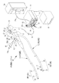
図1に示すように、内視鏡システム10は、被検者の体腔内を撮影する内視鏡11と、この内視鏡11の機能を補助する補助具12と、体腔内を照明するための照明光を内視鏡11に供給する光源装置13と、内視鏡画像を生成するプロセッサ装置14と、このプロセッサ装置14が生成した内視鏡画像を表示するモニタ15とで構成されている。
As shown in FIG. 1, an endoscope system 10 includes an endoscope 11 that captures an image of a body cavity of a subject, an
内視鏡11は、被検者の体腔内に挿入される挿入部16と、挿入部16の基端部に連設され、医師や技師などの術者が操作を行うための手元操作部17と、手元操作部17に連設され、内視鏡11を光源装置13及びプロセッサ装置14に接続するためのユニバーサルケーブル18とを有している。また、この内視鏡11の内部には、手元操作部17から挿入部16の先端に掛けて、鉗子やスネアなどといった各種の処置具を挿通するための鉗子管路57(図2参照)が設けられている。挿入部16は、約6mmの外径を有する管状に形成されている。鉗子管路57は、約2mmの内径を有する管状に形成されている。
The endoscope 11 is connected to an
補助具12は、被検者の体腔内に挿入される挿入部35と、この挿入部35の基端部を内視鏡11の手元操作部17に取り付けるための取付部36とを有している。挿入部35は、内視鏡11の挿入部16と略同一もしくは僅かに細い外径を有する管状に形成されている。この補助具12の内部には、取付部36から挿入部35の先端に掛けて、内視鏡11の鉗子管路57よりも太い径を有する鉗子管路74(図4参照)が設けられている。
The
内視鏡11は、挿入部16を外鼻孔から挿入する、いわゆる経鼻内視鏡である。この内視鏡11は、挿入部を口から挿入する経口内視鏡に比べて挿入部16の径が細い。従って、挿入部16内に設けられる鉗子管路57の径も当然ながら細くなる。このため、内視鏡11では、経口内視鏡に比べて、使用できる処置具の大きさが制限されてしまう。
The endoscope 11 is a so-called transnasal endoscope that inserts the
内視鏡システム10は、一方の外鼻孔から内視鏡11の挿入部16を挿入するとともに、内視鏡11の挿入部16が挿入されていない他方の外鼻孔から補助具12の挿入部35を挿入し、これらを組み合わせて使用する。そして、補助具12の鉗子管路74で内視鏡11の鉗子管路57の機能を補助することにより、経鼻内視鏡である内視鏡11で検査を行う際にも、経口内視鏡と同程度の大きさの処置具を使用できるようにする。なお、一般的な経口内視鏡の鉗子管路の内径は、約3.2mmであるから、補助具12の鉗子管路74の内径は、3.2mm以上であることが好ましい。
The endoscope system 10 inserts the
内視鏡11の挿入部16は、周知のように、先端硬質部20、湾曲部21、及び軟性部22からなる。先端硬質部20には、硬質な金属材料などで形成された先端部本体の内部に撮像素子や観察光学系、及び照明光学系などが内蔵されている。
As is well known, the
湾曲部21は、手元操作部17に設けられた上下用湾曲操作部23、左右用湾曲操作部24の操作に連動して上下左右の4方向に湾曲するように構成されている。これにより、先端硬質部20の先端面を所望の方向に向けて体腔内の観察を行うことができる。軟性部22は、手元操作部17と湾曲部21との間を接続する部分であり、細径かつ長尺な管状に形成され、可撓性を有している。
The bending
手元操作部17には、各湾曲操作部23、24の他に、鉗子管路57に処置具を挿入するための鉗子入口25、体腔内に空気や水を送り込む送気・送水を行うための送気・送水ボタン26、体腔内に溜まった空気や残渣、体液などの吸引を行うための吸引ボタン27、及び洗浄水や薬液などの液体を観察対象に向けて噴射するためのウォータージェット口(WJ口)28などが設けられている。WJ口28には、シリンジポンプ(図示は省略)が着脱自在に接続される。観察対象に噴射する洗浄水や薬液などは、このシリンジポンプから供給される。なお、鉗子入口25とWJ口28とは、通常は着脱自在な栓により塞がれている。
In addition to the
ユニバーサルケーブル18には、手元操作部17と反対側の端部に、光源装置13に接続するためのライトガイド用コネクタ(LGコネクタ)30と、プロセッサ装置14に接続するためのビデオ用コネクタ(電気コネクタ)31とが設けられている。電気コネクタ31は、コード32を介してLGコネクタ30と接続されている。内視鏡11は、これらの各コネクタ30、31を介して各装置13、14に着脱自在に接続される。
The
また、LGコネクタ30には、送水用の水を貯留する送水タンク33を接続するためのジョイントと、吸引を行うための吸引圧を内視鏡11に供給する吸引装置34を接続するためのジョイントとが設けられている。LGコネクタ30は、送水用のジョイント及び送水チューブ33aを介して送水タンク33と接続されるとともに、吸引用のジョイント及び吸引チューブ34aを介して吸引装置34と接続されている。
Further, the
吸引用のジョイントは、内視鏡11内に形成された吸引管路と接続されている。この吸引管路は、手元操作部17内で鉗子管路57に接続されるとともに、吸引ボタン27の押下操作に連動するバルブによって閉塞されている。吸引ボタン27を押下操作すると、吸引管路が開通し、鉗子管路57から吸引管路と吸引チューブ34aとを経由して吸引装置34へと至る経路が繋がる。そして、この経路が繋がると、吸引装置34の吸引圧によって吸引が開始され、挿入部16の先端から体腔内に溜まった空気や体液などが吸引される。また、吸引装置34は、洗浄水や体液などの液体を吸引すると、その液体を吸引タンク34bに貯留する。このように、鉗子管路57は、吸引管路としての機能も兼ねている。
The suction joint is connected to a suction pipe formed in the endoscope 11. The suction line is connected to the forceps line 57 in the
光源装置13には、照明光を照射する光源ランプが内蔵されている。光源ランプは、接続されたLGコネクタ30の光入射面と対面するように配置されており、その光入射面に照明光を入射させる。LGコネクタ30に入射した照明光は、内視鏡11内に設けられたライトガイドによって先端硬質部20内の照明光学系に導かれ、先端硬質部20の先端面から照射される。
The
また、光源装置13には、送気・送水用の空気を内視鏡11に供給するためのポンプが設けられている。光源装置13から供給される空気は、LGコネクタ30を介して内視鏡11内に形成された送気管路に送り込まれるとともに、送水チューブ33aに送り込まれる。
Further, the
送水チューブ33aには、光源装置13から供給される空気を送水タンク33に送り込んで送水タンク33内に圧力を加える送気用の管路と、加えられた圧力によって押し出される送水タンク33内の水を送り出す送水用の管路とが形成されている。この送水用の管路は、LGコネクタ30で内視鏡11内に形成された送水管路に接続される。
In the
内視鏡11の送気管路、及び送水管路は、送気・送水ボタン26の押下操作に連動するバルブによって閉塞されている。送気・送水ボタン26の中央には、光源装置13から供給される空気をリークする穴が設けられている。バルブは、送気・送水ボタン26の押下操作に応じて各管路の閉塞及び開通を切り替える。送気・送水ボタン26の穴を指で塞ぐと、光源装置13から供給された空気が送気管路に送られ、挿入部16の先端から吐出される。そして、送気・送水ボタン26を押下操作すると、送気管路が閉塞して送水管路が開通し、送水タンク33から送り出された水が挿入部16の先端から吐出される。
The air supply conduit and the water supply conduit of the endoscope 11 are closed by a valve that is interlocked with the pressing operation of the air /
なお、内視鏡11の送気管路、及び送水管路は、バルブよりも下流側の部分で送気・送水管路58(図2参照)として1本にまとめられている。挿入部16内では、光源装置13からの空気と送水タンク33からの水とが同じ送気・送水管路58内を通って挿入部16の先端に送られる。
In addition, the air supply pipe line and the water supply pipe line of the endoscope 11 are integrated into one as an air supply / water supply pipe line 58 (see FIG. 2) at a portion downstream of the valve. In the
プロセッサ装置14には、内視鏡11に設けられた撮像素子から出力される撮像信号に各種の画像処理を施して内視鏡画像を生成する画像処理回路が設けられている。画像処理回路は、内視鏡画像をコンポジット信号やRGBコンポーネント信号にエンコードし、モニタ15に出力する。これにより、モニタ15に内視鏡画像が表示される。
The
補助具12の挿入部35は、先端部37と軟性部38とで構成されている。先端部37は、内視鏡11の先端硬質部20と同様に、金属などの硬質な材料で形成されている。軟性部38も、内視鏡11の軟性部22と同様に構成されており、細径かつ長尺な管状に形成されるとともに、可撓性を有し、先端部37と取付部36との間を接続する。
The
挿入部35の先端には、リング状に形成された一対のバルーン(拘束部材)40、41が設けられている。各バルーン40、41には、例えば、ポリウレタンなどの樹脂材料が用いられており、所定の大きさ以上に膨らまないようになっている。また、各バルーン40、41は、体腔内に挿入する際に体壁を傷付けないよう表面が滑らかに形成されている。これらの各バルーン40、41は、内視鏡11の挿入部16の先端に補助具12の挿入部35の先端を固定するために用いられる。なお、図1では、各バルーン40、41が拡張した状態を示している。
A pair of balloons (restraining members) 40 and 41 formed in a ring shape are provided at the distal end of the
挿入部35の基端付近には、分岐するように形成されたチューブ42が設けられている。そして、挿入部35は、このチューブ42を介して各バルーン40、41を拡張/収縮させるためのシリンジポンプ43と接続されている。チューブ42は、ゴムなどで形成されており、可撓性を有している。
Near the proximal end of the
シリンジポンプ43は、ピストン43aの押し引きに応じて空気を吐出/吸引する。ピストン43aを押し込んでシリンジポンプ43から空気を吐出させると、各バルーン40、41の内部空間に空気が送り込まれ、各バルーン40、41が拡張する。ピストン43aを引き戻してシリンジポンプ43に空気を吸引させると、各バルーン40、41の内部空間の空気が吸い出され、各バルーン40、41が収縮する。このように、シリンジポンプ43の操作に応じて各バルーン40、41が拡張/収縮する。なお、各バルーン40、41を拡張/収縮させる媒体は、空気に限ることなく、他の気体でもよいし、水などの液体でもよい。
The
取付部36は、略T字の三又管状に形成されており(図5参照)、中央部の管路を介して挿入部35と接続されている。取付部36の一端部は、略円筒状に形成された鉗子入口25の外径と略同一の内径に形成されている。取付部36は、この一端部を鉗子入口25に嵌合させることによって、補助具12を手元操作部17に着脱自在に取り付ける(図5参照)。
The
取付部36の他端部は、内視鏡11の鉗子管路57及び補助具12の鉗子管路74に処置具を挿入するための鉗子入口44になっている。このように、補助具12は、取付部36によって内視鏡11の鉗子入口25に取り付けられた後、鉗子入口44及び三又管状に形成された取付部36の内部管路を介して内視鏡11の鉗子管路57と補助具12の鉗子管路74とに処置具を選択的に挿入することができるように構成されている。また、鉗子入口44は、内視鏡11の鉗子入口25と略同一の形状に形成されている。これにより、内視鏡11の鉗子入口25に用いられる鉗子栓を鉗子入口44に取り付けることができる。
The other end of the
前述のように、内視鏡11の鉗子管路57は、吸引管路としての機能も有している。鉗子入口25に補助具12を取り付けて吸引ボタン27を押下操作した場合、三又管状に形成された取付部36を介して内視鏡11の鉗子管路57と補助具12の鉗子管路74とが接続されているため、各鉗子管路57、74から同時に吸引が行われる。これにより、補助具12を併用して吸引を行った場合には、単位時間当たりの吸引量を増やすことができる。
As described above, the forceps conduit 57 of the endoscope 11 also has a function as a suction conduit. When the
なお、補助具12の取付部36を鉗子入口25に取り付けるタイミングとしては、各挿入部16、35を体腔内に挿入する前と挿入後とが考えられる。この際、後者の場合には、補助具12の挿入部35の長さを内視鏡11の挿入部16よりも長くしておくと作業がし易いので望ましい。
In addition, as timing which attaches the
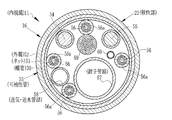
図2に示すように、内視鏡11の軟性部22は、内側より順に可撓性を保ちながら内部を保護するフレックスと呼ばれる螺管50と、この螺管50の上に被覆され外層52の樹脂を保持するブレードと呼ばれるネット51と、このネット51上に樹脂を被着した外層52との3層からなる可撓性管53で構成されている。
As shown in FIG. 2, the
可撓性管53の内部には、ライトガイド54、55、アングルワイヤ56、鉗子管路57、送気・送水管路58、多芯ケーブル59、及び、ウォータージェット管路(WJ管路)60などが設けられている。各ライトガイド54、55は、光源装置13から供給される照明光を先端硬質部20の照明光学系に導く。アングルワイヤ56は、上下用と左右用との2本のアングルワイヤを各湾曲操作部23、24の操作に連動する2つのプーリに各々掛け回してそれら先端を湾曲部21に向けて挿通しているので可撓性管53の内部には4本あり、それぞれが密着コイルパイプ56aの中に挿通されている。
Inside the flexible tube 53, there are
鉗子管路57は、鉗子入口25又は鉗子入口44から挿入された処置具を先端硬質部20に案内する。送気・送水管路58は、送気・送水ボタン26の押下操作に応じて供給される空気や水を先端硬質部20に送る。多芯ケーブル59は、主に、映像信号処理部から撮像センサを駆動するための信号を送るとともに、撮影センサから得られる撮像信号を映像信号処理部に送るためのケーブルであり、複数の信号線を保護被膜で覆った断面形状になっている。WJ管路60は、WJ口28に接続されたシリンジから供給される水や薬液などの液体を先端硬質部20に送る。
The forceps conduit 57 guides the treatment instrument inserted from the
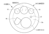
図3に示すように、内視鏡11の先端硬質部20の先端面20aには、観察窓62、一対の照明窓63、64、鉗子出口65、送気・送水ノズル66、及びウォータージェットノズル(WJノズル)67などが設けられている。観察窓62には、観察対象からの像光を取り込むための観察光学系の一部が配されている。照明窓63、64は、観察窓62を挟んだ両側に設けられ、ライトガイド54、55を介して供給される光源装置13からの光を観察対象に向けて照射する。
As shown in FIG. 3, an
鉗子出口65は、鉗子管路57に挿入された処置具の先端を導出させる。送気・送水ノズル66は、送気・送水ボタン26の押下操作に応じて送気・送水管路58から送られる空気や水を噴射する。送気・送水ノズル66の噴射口は、噴射する空気や水が観察窓62に向かうように形成されている。これにより、送気・送水ノズル66から噴射された空気や水によって観察窓62が洗浄され、観察窓62に付着した汚れなどを洗い流すことができる。WJノズル67は、WJ管路60から送られる洗浄水や薬液などの液体を噴射する。WJノズル67の噴射口は、観察窓62の光軸方向に向いて形成されており、噴射する液体を観察対象に直接吹き付ける。
The
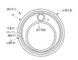
図4に示すように、補助具12の軟性部38は、内視鏡11の軟性部22と同様、螺管70、ネット71、及び外層72との3層からなる可撓性管73で覆われている。螺管70は、可撓性を保ちながら内部を保護する。ネット71は、螺管70の上に被覆され、外層62の樹脂を保持する。外層72は、ネット71上に樹脂を被着したものである。
As shown in FIG. 4, the
この可撓性管73内には、鉗子管路74と、バルーン用送気管路75とが設けられている。これらの各管路74、75は、例えば、合成樹脂製のフレキシブル管からなる。鉗子管路74は、鉗子入口44から挿入された処置具を先端部37に案内する。バルーン用送気管路75は、各バルーン40、41とシリンジポンプ43との間の空気の流通を媒介する。
In the
図5に示すように、先端部37の先端面37aには、鉗子管路74に挿入された処置具の先端を導出させる鉗子出口76が形成されている。また、軟性部38の側面には、各バルーン40、41を取り付けるための2つの凹部77、78が設けられている。各凹部77、78は、可撓性管73の外面を略円形に窪ませるようにして形成されている。また、各凹部77、78は、挿入部35の軸方向に沿って一直線上に並ぶように配置されている。
As shown in FIG. 5, a
各バルーン40、41には、各凹部77、78の形状に応じた略円板状の取付部40a、41aが形成されている。各取付部40a、41aの中心には、各バルーン40、41の内部空間に繋がる貫通孔が形成されており、各取付部40a、41aは、内部空間に空気を流通させて各バルーン40、41を拡張/収縮させるための流通口になっている。
The
各バルーン40、41は、各取付部40a、41aを各凹部77、78に嵌合させることにより、挿入部35に対して着脱自在に取り付けられる。また、各凹部77、78の内側面には、略半円形に窪んだ係合溝が形成され、各取付部40a、41aの側面には、略半円形に突出した係合突起が形成されている。各バルーン40、41は、挿入部35に取り付けられた際に、係合突起を係合溝に係合させる。これにより、各バルーン40、41が挿入部35から簡単に外れないようになるとともに、各取付部40a、41aと各凹部77、78との気密が保たれるようになる。
The
なお、図5では、便宜的に、紙面と直交する方向を向いて各バルーン40、41が挿入部35に取り付けられるように図示しているが、実際には、図1などに示すように、各バルーン40、41は、挿入部35の軸方向を向いて挿入部35に取り付けられる。
In FIG. 5, for convenience, the
バルーン用送気管路75の一方の端部75aは、チューブ42と接続されている。バルーン用送気管路75の他方の端部75bは、先端側の凹部77と接続されている。そして、バルーン用送気管路75には、分岐部75cが形成されており、この分岐部75cを介して凹部78と接続されている。これにより、チューブ42やバルーン用送気管路75などを介して各バルーン40、41とシリンジポンプ43とが接続され、ピストン43aを押し引きすることで各バルーン40、41が拡張/収縮する。
One
補助具12の挿入部35の先端を内視鏡11の挿入部16の先端に固定する場合には、先ず、シリンジポンプ43から空気を供給して各バルーン40、41を拡張させた後、図6(a)に示すように、各先端面20a、37aが同じ方向を向くように各挿入部16、35を平行にするとともに、挿入部35に取り付けられたバルーン41よりも挿入部16の先端面20aが後方に位置するように、それぞれを配置する。
When fixing the distal end of the
そして、図6(b)に示すように、挿入部16の先端面20aを挿入部35の先端面37aに近付けるように挿入部16を前方に移動させて挿入部16を各バルーン40、41に通し、各先端面20a、37aを揃える。
Then, as shown in FIG. 6B, the
各バルーン40、41の内径は、挿入部16を通し易いように、挿入部16の外径よりも僅かに大きく形成されている。また、バルーン40は、各先端面20a、37aを揃えて各挿入部16、35を並べた際に、湾曲部21の前端付近に位置するように配置されている。さらに、バルーン41は、各先端面20a、37aを揃えて各挿入部16、35を並べた際に、湾曲部21の後端付近に位置するように配置されている。
The inner diameters of the
挿入部16を各バルーン40、41に通し、各先端面20a、37aを揃えて各挿入部16、35を並べた後、シリンジポンプ43で空気を吸引し、各バルーン40、41を収縮させる。各バルーン40、41を拡張した状態から収縮させると、内径が狭まる。これにより、図6(c)に示すように、収縮した各バルーン40、41によって挿入部16が拘束され、挿入部16の先端に挿入部35の先端が固定される。すなわち、本例では、各バルーン40、41とシリンジポンプ43、及びこれらを接続するバルーン用送気管路75などの各管路によって請求項記載の固定手段が構成される。
The
このように挿入部35の先端を挿入部16の先端に固定すれば、各湾曲操作部23、24の湾曲操作にともなう湾曲部21の湾曲に追従して挿入部35の軟性部38が湾曲し、内視鏡11の先端面20aと補助具12の先端面37aとが同じ方向を向くようになる。これにより、内視鏡11と補助具12とを組み合わせて使用する際にも、内視鏡11の湾曲操作だけでよくなるので、操作が煩雑になることを防止することができる。
If the distal end of the
また、各バルーン40、41で拘束する方法では、内視鏡11に手を加えることなく各挿入部16、35の先端を固定することができるので、既存の内視鏡11に対して補助具12を組み合わせることができる。
Moreover, in the method of restraining with each
また、観察窓62が先端面20aに設けられているため、挿入部16を各バルーン40、41に通す場合には、内視鏡画像内に各バルーン40、41が映し出される。従って、術者は、内視鏡画像に表示された各バルーン40、41を見ながら操作を行うことができるので、容易に各バルーン40、41に挿入部16を通すことができる。
In addition, since the
さらに、各挿入部16、35の固定を解除する場合には、シリンジポンプ43から再び空気を供給して各バルーン40、41を拡張させ、各バルーン40、41から挿入部16を引き抜くだけでよいので、固定を解除する際の操作が煩雑になることもない。
Further, in order to release the fixing of each
次に、図7に示すフローチャートを参照しながら上記構成による内視鏡システム10の作用について説明する。経鼻内視鏡検査では、まず前処置として、内視鏡11の挿入部16を挿入するために外鼻孔の奧の鼻腔から中(下)鼻道に麻酔を行うとともに挿通テストを行い、挿入部16が挿通可能な挿入経路のある鼻腔を決定する。前処置は座位又は仰臥位で行い、その後に、仰臥位又は左側臥位で挿入部16を一方の外鼻孔に挿入していく。挿入部16は、外鼻孔から挿入された後、中鼻道又は下鼻道、後鼻孔(内鼻孔)、食道を経由して胃もしくは十二指腸へと到達する。
Next, the operation of the endoscope system 10 configured as described above will be described with reference to the flowchart shown in FIG. In the transnasal endoscopy, as a pretreatment, in order to insert the
十二指腸や胃を観察して処置や治療が必要ないと判断された場合は、内視鏡11の挿入部16を体腔から引き抜いて検査を終了する。また、病変が見つかった場合で、かつ内視鏡11の小径の鉗子管路57を使って処置又は治療を行える場合には、その鉗子管路57を使って小型のスネアや生体鉗子などの処置具を挿入して処置又は治療を行う。
When it is determined that treatment or treatment is not necessary by observing the duodenum or stomach, the
内視鏡11の鉗子管路57では処置又は治療が行えないと判断された場合には、補助具12を併用する。補助具12を内視鏡11と併用する場合、まず補助具12の挿入部35を他方の外鼻孔に挿入するため、他方の外鼻孔の奧の鼻腔に麻酔を行う。次に、補助具12の挿入部35の先端を内視鏡11の挿入部16の先端に固定するため、後鼻孔から食道までの範囲に先端面20aが位置するように、内視鏡11の挿入部16を引き戻す。
When it is determined that treatment or therapy cannot be performed in the forceps conduit 57 of the endoscope 11, the
挿入部16を引き戻した後、他方の外鼻孔から補助具12の挿入部35を挿入し、その先端面37aを後鼻孔から食道までの範囲に位置させる。この際、各バルーン40、41は、空気を抜いて収縮させ、挿入部35の外面に沿わせるようにしておく。
After the
各挿入部16、35を挿入した後、シリンジポンプ43から空気を供給して各バルーン40、41を拡張させる。そして、前述のように、各バルーン40、41で挿入部16を拘束することにより、内視鏡11の挿入部16の先端に補助具12の挿入部35の先端を固定する。その後、補助具12の取付部36を内視鏡11の鉗子入口25に取り付け、各挿入部16、35の挿入を開始する。
After inserting each
各挿入部16、35を挿入する場合には、モニタ15の画面を見ながら各湾曲操作部23、24を操作し、内視鏡11の湾曲部21を湾曲させながら挿入を行っていく。この際、補助具12の軟性部38は、各バルーン40、41の拘束によって内視鏡11の湾曲部21に密着しているため、内視鏡11の湾曲部21と一緒に湾曲し、また、内視鏡11の挿入部16の挿入に追従して挿入される。このため、内視鏡11の挿入部16のみをもって挿入していくだけで補助具12の挿入部35も一緒に挿入される。
When inserting the
各挿入部16、35を挿入して、モニタ15の画面に処置又は治療を施す必要のある患部が映し出されると、スネアや生検鉗子などの処置具を、取付部36に設けられた鉗子入口44から補助具12の鉗子管路74に挿入する。そして、処置具の先端処置部材、例えば一対の鉗子カップや絞断用ループなどを補助具12の鉗子出口76から導出させて処置又は治療を行う。
When each of the
処置具の一例として説明した生検鉗子は一般に、先端に一対の鉗子カップが開閉自在に取り付けられた操作ワイヤを可撓性シース内に挿通し、操作ワイヤの後端を鉗子入口の外で軸線方向に進退操作することによって、可撓性シースの先端部内に設けられたリンク構造により鉗子カップを嘴状に開閉駆動する。生検鉗子は、主に組織採取を目的として使用されており、適合する鉗子管路の内径としては、例えば2.8mm以上必要になるものが多い。 A biopsy forceps described as an example of a treatment tool generally has an operation wire having a pair of forceps cups attached to the tip of the biopsy forceps so as to be freely opened and closed, and the rear end of the operation wire is positioned outside the forceps inlet. By moving forward and backward in the direction, the forceps cup is opened and closed in a hook shape by the link structure provided in the distal end portion of the flexible sheath. Biopsy forceps are mainly used for the purpose of tissue collection, and the inner diameter of a compatible forceps conduit often requires, for example, 2.8 mm or more.
また、スネアは一般に、弾性ワイヤを曲げて形成された絞断用ループがシースの手元側からの操作によりシースの先端内に出入りするように構成されていて、その絞断用ループが、シース内に引き込まれた状態では窄まった状態に弾性変形し、シース内から前方に押し出されるとループ状に膨らんだ形状に広がるようになっている。スネアでポリープ切除を行う場合には、ポリープの根元部分を絞断用ループで適度に締め付けた状態にしてから絞断用ループに高周波電流を通電することにより、絞断用ループに接触している部分の生体組織を焼灼して切断と凝固を同時に行う。このスネアも、適合する鉗子管路の内径が、例えば2.8mm以上必要になるものが多い。 In addition, a snare is generally configured such that a squeezing loop formed by bending an elastic wire enters and exits the sheath tip by operation from the proximal side of the sheath. In the state of being pulled in, it is elastically deformed into a constricted state, and when it is pushed forward from within the sheath, it expands into a loop-like shape. When polypectomy is performed with a snare, the root portion of the polyp is properly tightened with the loop for squeezing, and then a high-frequency current is applied to the squeezing loop to make contact with the squeezing loop. A part of living tissue is cauterized and cut and coagulated simultaneously. Many of these snares require an inner diameter of a compatible forceps conduit of, for example, 2.8 mm or more.
このようなスネアや生検鉗子などの処置具を補助具12の鉗子管路74を使用して、例えば組織を採る組織採取(バイオプシ)、異物の摘出、出血を止める、腫瘍の摘出、胆石の破砕等の治療や処置を行う。また、体内汚物や血液その他の体液などを吸引したい場合、手元操作部17の吸引ボタン27を押下操作すると、内視鏡11の鉗子出口65のみならず、補助具12の鉗子出口76からも吸引するため、迅速な吸引を行うことができ、また、双方の鉗子出口65、76から同時に吸引することができるので、生体組織を多く採取することができる。
Such a treatment tool such as a snare or a biopsy forceps is used by using the
治療又は処置を終了した後には、補助具12の鉗子入口44から処置具を引き抜き、しかる後に、双方の挿入部16、35をゆっくりと引き抜いていく。この途中、例えば後鼻孔から食道までの範囲を通過するまでに、双方の挿入部16、35の先端の固定を解除する。固定の解除は、シリンジポンプ43から空気を供給して各バルーン40、41を拡張させ、各バルーン40、41から挿入部16を引き抜くことによって行われる。各挿入部16、35の固定を解除した後には、補助具12、内視鏡11の順に各挿入部16、35を個別に引き抜く。最後に、補助具12の取付部36を手元操作部17の鉗子入口25から外す。
After the treatment or treatment is finished, the treatment tool is pulled out from the
以上により、内視鏡11と補助具12とを組み合わせて使用した場合の検査が終了する。なお、内視鏡11の鉗子管路57を使って処置又は治療が行えないことが初めから分かっている場合には、最初から補助具12を使えばよい。
By the above, the test | inspection at the time of using the endoscope 11 and the
上記実施形態では、各取付部40a、41aを各凹部77、78に嵌合させることによって各バルーン40、41を挿入部35に着脱自在に取り付けるようにしたが、各バルーン40、41の取り付け方法は、これに限定されるものではない。例えば、バルーン用送気管路75に繋がる突起部を挿入部35の外面に設け、この突起部に各バルーン40、41の流通口を嵌入させることによって取り付けるようにしてもよい。また、挿入部35に対して着脱自在にすることなく、接着剤などで各バルーン40、41を挿入部35に固着するようにしてもよい。
In the above embodiment, each of the
上記実施形態では、シリンジポンプ43を用いて各バルーン40、41を拡張/収縮させるようにしたが、これに限ることなく、ロータリポンプなどの他のポンプを用いて各バルーン40、41を拡張/収縮させてもよい。
In the above embodiment, the
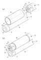
上記実施形態では、リング状に形成された各バルーン40、41によって内視鏡11の挿入部16を拘束するようにしたが、これに限ることなく、例えば、図8(a)、(b)に示すように、円筒状に形成されたバルーン90によって挿入部16を拘束するようにしてもよい。こうした円筒状のバルーン90では、一箇所から空気の供給/吸引を行えばよいので、バルーン用送気管路75に分岐部75cを設ける必要がない。従って、円筒状のバルーン90を用いる場合には、リング状の各バルーン40、41を用いる場合と比べてバルーン用送気管路75の構成を簡潔にすることができる。
In the above-described embodiment, the
なお、円筒状のバルーン90を用いる場合に、複数の箇所から空気の供給/吸引を行うようにしても勿論よい。また、拘束した内視鏡11の挿入部16を補助具12の挿入部35に密着させるため、バルーン90は、少なくとも両端部と中央付近との3箇所で挿入部35に取り付けられていることが好ましい。
Of course, when the
また、バルーンに限ることなく、例えば、図9に示す補助具100のように、挿入部35の内部空間に鉗子管路74とは別に、スネア型の拘束具101を挿通するための拘束用管路102を設け、拘束具101の先端に設けた拘束用ループ(紐体)103で内視鏡11の挿入部16を拘束して、各挿入部16、35の先端を固定する構造としてもよい。
In addition to the balloon, for example, a restraining tube for inserting the snare-
拘束用管路102は、鉗子管路74に比べ小径となっており、一端が補助具100の先端に設けた管路出口104に、他端が後端部に設けた管路入口105にそれぞれ接続されている。拘束具101は、拘束用管路102内に移動自在に収容されている。拘束具101の先端には、弾性ワイヤを折り曲げて形成した開閉自在な拘束用ループ103が設けられている。また、拘束具101の後端には、管路入口105から導出するハンドル106が設けられている。本例では、この拘束具101と拘束用管路102とによって、請求項記載の固定手段が構成される。
The restraining
拘束用ループ103は、ハンドル106を押し引きすることで、拘束用管路102内に収納される位置と、拘束用管路102から押し出された位置との間で移動する。また、弾性ワイヤからなる拘束用ループ103は、拘束用管路102から押し出された際に環状に膨らむように予め癖付けられている。挿入部35を外鼻孔から挿入するときには、拘束用ループ103を拘束用管路102内に収納して窄まった状態にしておく。
The restraining
各挿入部16、35の先端同士を固定するときには、拘束用ループ103を拘束用管路102から押し出して環状に膨らませる。そして、膨らんだ拘束用ループ103に内視鏡11の挿入部16の先端を通した後、ハンドル106を引いて拘束用ループ103を窄める。このように、拘束用管路102から押し出された部分の長さを変化させることで、拘束用ループ103によって挿入部16が拘束され、挿入部16の先端に挿入部35の先端が固定される。従って、拘束用ループ103を有する拘束具101を用いても、バルーンで拘束する場合と同様の効果を得ることができる。
When the distal ends of the
なお、挿入部16の湾曲操作に挿入部35を追従させやすいように、管路出口104は、先端部37の後端の近くに形成することが好ましい。また、図9の例では、弾性ワイヤからなる拘束用ループ103を紐体として示したが、紐体は、これに限ることなく、例えば、樹脂製の糸や細径な金属線など、拘束が可能な強度を有する紐状のものであれば如何なるものでもよい。但し、押し出した際にも紐体が窄まっていると、挿入部16を挿入し難いので、上述の拘束用ループ103のように、拘束用管路102から押し出した際に膨らむ構成にしておくことが好ましい。
It should be noted that the
上記各実施形態では、内視鏡11の挿入部16を環状に形成されたバルーンや弾性ワイヤに通し、これらで拘束することによって挿入部16に補助具の挿入部35を固定する構成としたが、これに限ることなく、各挿入部16、35の先端同士が固定できれば、如何なる構成としてもよい。例えば、クリップ状に形成された把持部材を補助具の挿入部の先端に設け、この把持部材で内視鏡の挿入部の先端を把持することによって、内視鏡の挿入部の先端に補助具の挿入部の先端を固定するようにしてもよい。
In each of the above-described embodiments, the
上記各実施形態では、補助具に鉗子管路74を設け、内視鏡11の鉗子管路57の機能を補助するようにしたが、これに限ることなく、例えば、補助具にライトガイドを設け、内視鏡11の各ライトガイド54、55の機能を補助してもよいし、補助具に送気・送水管路を設け、内視鏡11の送気・送水管路58の機能を補助してもよいし、補助具にWJ管路を設け、内視鏡11のWJ管路60の機能を補助してもよい。さらには、これらを組み合わせて補助具に設け、内視鏡11の複数の機能を補助するようにしてもよい。
In each of the above embodiments, the
経鼻内視鏡である内視鏡11は、鉗子管路57と同様に、各ライトガイド54、55、送気・送水管路58などの径も、経口内視鏡に比べて細くなっており、経鼻内視鏡としては、WJノズル67、WJ管路60を備えていないものが多い。各ライトガイド54、55の小径化は、照明光の光量や配光特性の低下を招き、遠景が暗くなる。また、送気・送水管路58の小径化は、送り込む空気や水の単位時間当たりの流量の低下を招き、胃の拡張、及び血液や粘液などの洗浄に時間が掛かってしまう。そして、WJ管路60を備えていないと、洗浄水や薬液などの噴射を行うことができない。
In the endoscope 11 which is a transnasal endoscope, the diameters of the light guides 54 and 55 and the air /
そこで、補助具にライトガイドを設ければ、照明光の光量を向上させ、経口内視鏡と同程度の明るさ、配光特性で検査を行うことができる。また、補助具に送気・送水管路を設ければ、送り込む流体の単位時間当たりの流量を経口内視鏡と同程度にすることができる。さらに、補助具にWJ管路を設ければ、ウォータージェットとして噴射する液体の液量を経口内視鏡と同程度にすることができる。 Thus, if a light guide is provided in the auxiliary tool, the amount of illumination light can be improved, and inspection can be performed with the same brightness and light distribution characteristics as those of an oral endoscope. In addition, if an air supply / water supply conduit is provided in the auxiliary tool, the flow rate per unit time of the fluid to be fed can be set to the same level as that of the oral endoscope. Furthermore, if the auxiliary tool is provided with a WJ pipe, the amount of liquid ejected as a water jet can be made comparable to that of an oral endoscope.
上記各実施形態では、取付部36を介して挿入部35の基端部が内視鏡11の手元操作部17に着脱自在に取り付けられるようにしたが、これに限ることなく、挿入部の基端部を取り付けない構成としてもよい。
In each of the above embodiments, the base end portion of the
10 内視鏡システム
11 内視鏡
12 補助具
16 挿入部
17 手元操作部(操作部)
35 挿入部
36 取付部
40、41 バルーン(拘束部材)
102 拘束用管路
103 拘束用ループ(紐体)
DESCRIPTION OF SYMBOLS 10 Endoscope system 11
35
102 Constraining
Claims (4)
リング状又は円筒状に形成され、内部空間に流体を送り込むことで拡張するとともに、内部空間の流体を吸い出すことで収縮する拘束部材を備えており、前記拘束部材は、拡張/収縮にともなう内径の変化によって、内部に通された前記内視鏡の挿入部を拘束し、前記各挿入部の先端が同じ方向を向くように前記各挿入部の先端同士を着脱自在に固定することを特徴とする補助具。 Used in combination with an endoscope having an insertion portion inserted into the body cavity from one outer nostril, and having an insertion portion that assists the function of the endoscope by being inserted into the body cavity from the other outer nostril In assistive devices,
It is formed in a ring shape or a cylindrical shape, and includes a restraining member that expands by sending fluid into the internal space and contracts by sucking out the fluid in the internal space, and the restraining member has an inner diameter associated with expansion / contraction. a change, to restrain the insertion portion of the endoscope is passed through the inside, characterized and Turkey tip of each insertion portion to secure detachably the tips of the respective insertion portions so as to face the same direction Auxiliary tool.
前記補助具の挿入部には、その基端部を前記操作部に着脱自在に取り付けるための取付部が設けられていることを特徴とする請求項1に記載の補助具。 The endoscope has an operation unit that is connected to a proximal end portion of the insertion portion and performs a bending operation of the insertion portion,
The assisting tool according to claim 1, wherein the insertion part of the assisting tool is provided with an attaching part for detachably attaching the base end part to the operating part.
前記内視鏡と組み合わせて使用され、他方の外鼻孔から体腔内に挿入されることで前記内視鏡の機能を補助する挿入部を有する補助具とからなる内視鏡システムにおいて、
前記補助具は、リング状又は円筒状に形成され、内部空間に流体を送り込むことで拡張するとともに、内部空間の流体を吸い出すことで収縮する拘束部材を備えており、前記拘束部材は、拡張/収縮にともなう内径の変化によって、内部に通された前記内視鏡の挿入部を拘束し、前記各挿入部の先端が同じ方向を向くように前記各挿入部の先端同士を着脱自在に固定することを特徴とする内視鏡システム。 An endoscope having an insertion portion to be inserted into a body cavity from one nostril;
In an endoscope system comprising an auxiliary tool that is used in combination with the endoscope and has an insertion portion that assists the function of the endoscope by being inserted into a body cavity from the other nostril.
The auxiliary tool is formed in a ring shape or a cylindrical shape, and includes a restraining member that expands by sending a fluid into the inner space and contracts by sucking out the fluid in the inner space. The insertion portion of the endoscope passed through the inside is restrained by the change in the inner diameter accompanying the contraction, and the distal ends of the insertion portions are detachably fixed so that the distal ends of the insertion portions face the same direction. the endoscope system according to claim and Turkey.
Priority Applications (5)
| Application Number | Priority Date | Filing Date | Title |
|---|---|---|---|
| JP2008244379A JP5390150B2 (en) | 2008-09-24 | 2008-09-24 | Auxiliary tool and endoscope system |
| KR1020117005185A KR101644842B1 (en) | 2008-09-08 | 2009-09-07 | Endoscope system, method of using the same, assisting tool and adapter |
| EP09811628.8A EP2339950A4 (en) | 2008-09-08 | 2009-09-07 | Endoscope system, method of using the same, assisting tool and adapter |
| CN200980135135.6A CN102149312B (en) | 2008-09-08 | 2009-09-07 | Endoscope system, method of using the same, assisting tool and adapter |
| PCT/JP2009/065975 WO2010027109A1 (en) | 2008-09-08 | 2009-09-07 | Endoscope system, method of using the same, assisting tool and adapter |
Applications Claiming Priority (1)
| Application Number | Priority Date | Filing Date | Title |
|---|---|---|---|
| JP2008244379A JP5390150B2 (en) | 2008-09-24 | 2008-09-24 | Auxiliary tool and endoscope system |
Related Child Applications (1)
| Application Number | Title | Priority Date | Filing Date |
|---|---|---|---|
| JP2013211969A Division JP2014000480A (en) | 2013-10-09 | 2013-10-09 | Assist device and endoscope system |
Publications (2)
| Publication Number | Publication Date |
|---|---|
| JP2010075270A JP2010075270A (en) | 2010-04-08 |
| JP5390150B2 true JP5390150B2 (en) | 2014-01-15 |
Family
ID=42206468
Family Applications (1)
| Application Number | Title | Priority Date | Filing Date |
|---|---|---|---|
| JP2008244379A Expired - Fee Related JP5390150B2 (en) | 2008-09-08 | 2008-09-24 | Auxiliary tool and endoscope system |
Country Status (1)
| Country | Link |
|---|---|
| JP (1) | JP5390150B2 (en) |
Families Citing this family (4)
| Publication number | Priority date | Publication date | Assignee | Title |
|---|---|---|---|---|
| JP2013169276A (en) * | 2012-02-20 | 2013-09-02 | Fujifilm Corp | Coupling fixture for rigid endoscope apparatus, and rigid endoscope apparatus |
| WO2013137000A1 (en) * | 2012-03-12 | 2013-09-19 | テルモ株式会社 | Nasal endoscope |
| WO2014054775A1 (en) * | 2012-10-05 | 2014-04-10 | 富士フイルム株式会社 | Medical-use observation system, endoscope, and illumination tool |
| CN111265179B (en) * | 2020-02-26 | 2023-11-03 | 上海澳华内镜股份有限公司 | Auxiliary tool for advancing treatment tool and endoscope system |
Family Cites Families (4)
| Publication number | Priority date | Publication date | Assignee | Title |
|---|---|---|---|---|
| JPS5142227Y2 (en) * | 1974-03-28 | 1976-10-14 | ||
| JP3504517B2 (en) * | 1998-11-27 | 2004-03-08 | オリンパス株式会社 | Endoscope insertion shape detection device |
| JP2007111541A (en) * | 2002-05-29 | 2007-05-10 | Olympus Corp | Endoscope apparatus and connecting device for endoscope |
| JP4663345B2 (en) * | 2005-01-31 | 2011-04-06 | オリンパスメディカルシステムズ株式会社 | Endoscopic treatment tool |
-
2008
- 2008-09-24 JP JP2008244379A patent/JP5390150B2/en not_active Expired - Fee Related
Also Published As
| Publication number | Publication date |
|---|---|
| JP2010075270A (en) | 2010-04-08 |
Similar Documents
| Publication | Publication Date | Title |
|---|---|---|
| US10441143B2 (en) | Insertion assisting tool for endoscope | |
| JP4544924B2 (en) | Endoscopy tube | |
| KR101644842B1 (en) | Endoscope system, method of using the same, assisting tool and adapter | |
| JP5437300B2 (en) | Endoscope insertion aid | |
| JP6385029B2 (en) | Endoscope and endoscope system | |
| JP2012192080A (en) | Endoscopic device | |
| JP2007268147A (en) | Medical device | |
| JP2018138115A (en) | Endoscope | |
| JPWO2017183366A1 (en) | Instrument insertion aid | |
| JP5390150B2 (en) | Auxiliary tool and endoscope system | |
| JP5496140B2 (en) | Endoscope insertion aid | |
| JP5390146B2 (en) | Auxiliary tool and endoscope system using the same | |
| JP5384893B2 (en) | Endoscope system and auxiliary tool | |
| JP2012085860A (en) | Endoscope and endoscope system | |
| JP5384892B2 (en) | Endoscope system and auxiliary tool | |
| JP5415746B2 (en) | Endoscope system | |
| JP5305859B2 (en) | Endoscope system | |
| JP2010148549A (en) | Endoscope system and endoscope | |
| JP5514077B2 (en) | Endoscope hood and endoscope system | |
| JP2014000480A (en) | Assist device and endoscope system | |
| JP2010136990A (en) | Endoscope system and aid | |
| JP2005131107A (en) | External channel and endoscope apparatus equipped with the same | |
| JPH08280603A (en) | Cover type endoscope | |
| JP5384894B2 (en) | Adapter and endoscope system using the adapter | |
| JP5390151B2 (en) | Auxiliary tool and endoscope system using the same |
Legal Events
| Date | Code | Title | Description |
|---|---|---|---|
| A711 | Notification of change in applicant |
Free format text: JAPANESE INTERMEDIATE CODE: A711 Effective date: 20100619 |
|
| A621 | Written request for application examination |
Free format text: JAPANESE INTERMEDIATE CODE: A621 Effective date: 20110210 |
|
| A131 | Notification of reasons for refusal |
Free format text: JAPANESE INTERMEDIATE CODE: A131 Effective date: 20130410 |
|
| TRDD | Decision of grant or rejection written | ||
| A01 | Written decision to grant a patent or to grant a registration (utility model) |
Free format text: JAPANESE INTERMEDIATE CODE: A01 Effective date: 20130911 |
|
| A61 | First payment of annual fees (during grant procedure) |
Free format text: JAPANESE INTERMEDIATE CODE: A61 Effective date: 20131010 |
|
| R150 | Certificate of patent or registration of utility model |
Ref document number: 5390150 Country of ref document: JP Free format text: JAPANESE INTERMEDIATE CODE: R150 Free format text: JAPANESE INTERMEDIATE CODE: R150 |
|
| R250 | Receipt of annual fees |
Free format text: JAPANESE INTERMEDIATE CODE: R250 |
|
| R250 | Receipt of annual fees |
Free format text: JAPANESE INTERMEDIATE CODE: R250 |
|
| R250 | Receipt of annual fees |
Free format text: JAPANESE INTERMEDIATE CODE: R250 |
|
| R250 | Receipt of annual fees |
Free format text: JAPANESE INTERMEDIATE CODE: R250 |
|
| R250 | Receipt of annual fees |
Free format text: JAPANESE INTERMEDIATE CODE: R250 |
|
| LAPS | Cancellation because of no payment of annual fees |