JP5389605B2 - Image printing device - Google Patents
Image printing device Download PDFInfo
- Publication number
- JP5389605B2 JP5389605B2 JP2009247849A JP2009247849A JP5389605B2 JP 5389605 B2 JP5389605 B2 JP 5389605B2 JP 2009247849 A JP2009247849 A JP 2009247849A JP 2009247849 A JP2009247849 A JP 2009247849A JP 5389605 B2 JP5389605 B2 JP 5389605B2
- Authority
- JP
- Japan
- Prior art keywords
- printing
- unit
- image data
- image
- Prior art date
- Legal status (The legal status is an assumption and is not a legal conclusion. Google has not performed a legal analysis and makes no representation as to the accuracy of the status listed.)
- Expired - Fee Related
Links
Images


Landscapes
- Accessory Devices And Overall Control Thereof (AREA)
- Cleaning In Electrography (AREA)
- Control Or Security For Electrophotography (AREA)
- Facsimiles In General (AREA)
Description
本発明は、画像データを用紙上に印刷する画像印刷装置に関する。 The present invention relates to an image printing apparatus that prints image data on paper.
近年、プリンタや複写機、複合機等の画像印刷装置は、オフィス等において必需品になっている。このような画像印刷装置は、ユーザが直接操作して複写等を行うほか、LAN(Local Area Network)等のネットワークを通じて入力された画像データを用紙上に印刷できるようになっている。 2. Description of the Related Art In recent years, image printing apparatuses such as printers, copiers, and multifunction machines have become a necessity in offices and the like. Such an image printing apparatus can be directly operated by a user for copying and printing image data input through a network such as a LAN (Local Area Network) on a sheet.
ところで、画像印刷装置が用紙上に画像を印刷する場合、各印刷のジョブには、例えばA4サイズの用紙に印刷すべきであるとか、画像データに指定された画像処理を適用するとか、印刷後にパンチ穴を開けるとか、ステープル処理を行う等の印刷条件が設定される。例えば、写真等を含む画像データの印刷では写真を鮮明にするために印刷条件が設定される。カラー印刷では印刷される画像を所望の色合いにするために印刷条件が設定される。製本を目的とした印刷では用紙上の適切な位置に画像を配置するために印刷条件が設定される。 By the way, when the image printing apparatus prints an image on paper, each print job should be printed on, for example, A4 size paper, image processing specified in the image data is applied, or after printing Printing conditions such as punch holes and stapling are set. For example, in printing image data including a photograph or the like, printing conditions are set in order to make the photograph clear. In color printing, printing conditions are set in order to obtain a desired color for an image to be printed. In printing intended for bookbinding, printing conditions are set in order to place an image at an appropriate position on a sheet.
また、設定した印刷条件により印刷される画像が所望の状態であるか否かを確認するために、実際に印刷した印刷物の状態を確認することも行われる(例えば、特許文献1等参照。)。このような試し印刷では、得られた印刷物が所望の状態ではない場合、再度、印刷条件を設定して印刷する。試し印刷は、例えば、大量の枚数や部数を印刷する場合等に、意図しない印刷条件で大量の印刷物が生成されることを防止でき、非常に有益である。 In addition, in order to confirm whether or not an image to be printed is in a desired state based on the set printing conditions, the state of a printed matter that is actually printed is also confirmed (see, for example, Patent Document 1). . In such trial printing, if the obtained printed matter is not in a desired state, printing is performed again by setting printing conditions. Trial printing is very useful because it can prevent a large amount of printed matter from being generated under unintended printing conditions, for example, when printing a large number of copies or copies.
近年、画像印刷装置の多機能化に伴い、印刷ジョブに対してユーザが設定できる印刷条件の項目は増加し、その組み合わせの数も膨大になっている。また、画像印刷装置の性能を活用するために、様々な機能を組み合わせた印刷条件をユーザが設定して印刷することも多い。このような場合、試し印刷では、種々の設定項目が組み合わされた多数の印刷条件について実施され、その複数の印刷条件の中から所望の印刷物が得られる印刷条件が選択されることになる。 In recent years, with the increase in the number of functions of image printing apparatuses, the number of print condition items that can be set by a user for a print job has increased, and the number of combinations has also increased. Further, in order to utilize the performance of the image printing apparatus, the user often sets and prints printing conditions that combine various functions. In such a case, the trial printing is performed for a large number of printing conditions in which various setting items are combined, and a printing condition for obtaining a desired printed matter is selected from the plurality of printing conditions.
このような多数の印刷条件を順次設定して試し印刷を行う状況下では、ユーザは様々な設定項目を変更して印刷条件を設定する。このため、印刷された印刷物と印刷条件との対応関係が不明になると、最適な印刷条件を選択するための作業効率が著しく低下する。また、多数の印刷条件について試し印刷を実行する場合には、既に試し印刷を実行した印刷条件を再度設定してしまう状況が発生しうる。このように、一度実行した印刷条件と同一の印刷条件で再度印刷が行うことは、無駄な印刷物が生成されて用紙やトナーが無駄に消費される上、最適な印刷条件を選択するための作業効率を低下させることになる。 In a situation where trial printing is performed by sequentially setting a large number of printing conditions as described above, the user changes various setting items to set printing conditions. For this reason, when the correspondence between the printed material and the printing conditions becomes unclear, the work efficiency for selecting the optimum printing conditions is significantly reduced. Further, when trial printing is performed for a large number of printing conditions, a situation may occur in which the printing conditions for which trial printing has already been performed are set again. In this way, when printing is performed again under the same printing conditions as once executed, useless prints are generated and paper and toner are wasted, and work for selecting optimum printing conditions. Efficiency will be reduced.
本発明は、このような従来技術の課題を鑑みてなされたものであり、試し印刷を通じて印刷条件を選択する際に、効率良く最適な印刷条件を確認することができるとともに、用紙やトナーの無駄な消費を抑制できる、画像印刷装置を提供することを目的とする。 The present invention has been made in view of the above-described problems of the prior art, and when selecting printing conditions through trial printing, it is possible to efficiently check optimum printing conditions and to waste paper and toner. An object of the present invention is to provide an image printing apparatus that can suppress unnecessary consumption.
上述の目的を達成するために、本発明に係る画像印刷装置は以下の技術的手段を採用している。まず、本発明は、試し印刷機能を有する画像印刷装置を前提としている。そして、本発明に係る画像印刷装置は、画像形成部、印刷条件設定部、設定入力部、ID生成部、画像データ合成部、印刷実行部を備える。画像形成部は画像データを用紙上に印刷する。印刷条件設定部は、設定入力部を通じて登録された、画像形成部における画像データの印刷に適用される印刷条件を保持する。ID生成部は、印刷条件設定部に保持された印刷条件を特定する識別子を生成する。画像データ合成部は、試し印刷対象の画像データとID生成部が生成した識別子とを合成し、当該画像データが印刷される用紙の所定位置に識別子を配置した、試し印刷用画像データを生成する。例えば、所定位置は、用紙の余白部分である。印刷実行部は、画像データ合成部が生成した試し印刷用画像データを、印刷条件設定部に保持された印刷条件で画像形成部に印刷させる。 In order to achieve the above object, the image printing apparatus according to the present invention employs the following technical means. First, the present invention is premised on an image printing apparatus having a test printing function. The image printing apparatus according to the present invention includes an image forming unit, a printing condition setting unit, a setting input unit, an ID generation unit, an image data composition unit, and a print execution unit. The image forming unit prints the image data on a sheet. The printing condition setting unit holds printing conditions that are registered through the setting input unit and that are applied to the printing of the image data in the image forming unit. The ID generation unit generates an identifier for specifying the printing condition held in the printing condition setting unit. The image data synthesizing unit synthesizes the image data to be tested and the identifier generated by the ID generation unit, and generates test print image data in which the identifier is arranged at a predetermined position on the sheet on which the image data is printed. . For example, the predetermined position is a margin portion of the paper. The print execution unit causes the image forming unit to print the test print image data generated by the image data synthesis unit under the print conditions held in the print condition setting unit.
この画像印刷装置では、印刷条件を特定する識別子を試し印刷対象の画像データとともに用紙上に印刷することができる。すなわち、複数の異なる印刷条件を適用して試し印刷を実施した場合であっても、生成された複数の印刷物の中から所望の印刷物を選択するだけで、選択した用紙に印刷された識別子によってその印刷条件を速やかに特定することができる。したがって、最適な印刷条件を選択するための作業効率が向上する。 In this image printing apparatus, an identifier for specifying printing conditions can be printed on paper together with image data to be subjected to trial printing. That is, even when trial printing is performed by applying a plurality of different printing conditions, simply selecting a desired printed material from a plurality of generated printed materials, and the identifier is printed on the selected paper. Printing conditions can be specified quickly. Therefore, the work efficiency for selecting the optimum printing conditions is improved.
また、この画像印刷装置は、設定履歴記憶部、印刷条件比較部、報知部をさらに備えることができる。設定履歴記憶部は、一連の試し印刷において、印刷条件設定部に保持され、試し印刷が実行された印刷条件の履歴を記憶する。印刷条件比較部は、一連の試し印刷において、印刷条件設定部に新たに保持された印刷条件と、設定履歴記憶部に記憶された印刷条件とを比較する。報知部は、設定履歴記憶部に記憶された印刷条件に、印刷条件設定部に新たに保持された印刷条件と一致する印刷条件が含まれている場合、警告を発報する。
The image printing apparatus may further include a setting history storage unit, a printing condition comparison unit, and a notification unit. The setting history storage unit stores a history of printing conditions that are held in the printing condition setting unit and executed for trial printing in a series of trial printing . The printing condition comparison unit compares the printing condition newly held in the printing condition setting unit with the printing condition stored in the setting history storage unit in a series of trial printing . The notifying unit issues a warning when the printing condition stored in the setting history storage unit includes a printing condition that matches the printing condition newly held in the printing condition setting unit.
この構成では、ユーザが印刷条件を順次変更して試し印刷をする際に、同一の印刷条件で試し印刷が実行されるのを防止することができる。その結果、用紙やトナーが無駄な消費を抑制できるとともに、最適な印刷条件を選択するための作業効率が向上する。 With this configuration, it is possible to prevent the trial printing from being executed under the same printing conditions when the user sequentially changes the printing conditions to perform the trial printing. As a result, wasteful consumption of paper and toner can be suppressed, and work efficiency for selecting optimum printing conditions can be improved.
以上の画像印刷装置は、用紙の所定位置に印刷された識別子が入力される識別子入力部をさらに備え、印刷実行部が、入力された識別子により特定される印刷条件で印刷対象の全画像データを画像形成部に印刷させる構成にすることもできる。これにより、試し印刷において選択した印刷条件を示す識別子を入力するだけで、その印刷条件を画像形成装置に設定することができ、その印刷条件で本番印刷を実施することができる。すなわち、最適な印刷条件を選択するための作業効率がさらに向上する。 The above-described image printing apparatus further includes an identifier input unit for inputting an identifier printed at a predetermined position on the paper, and the print execution unit displays all image data to be printed under the printing conditions specified by the input identifier. It can also be configured to print on the image forming unit. Thus, simply by inputting an identifier indicating the printing condition selected in the trial printing, the printing condition can be set in the image forming apparatus, and the actual printing can be performed with the printing condition. That is, the work efficiency for selecting the optimum printing conditions is further improved.
本発明によれば、試し印刷を通じて印刷条件を選択する際に、効率良く最適な印刷条件を確認することができる。また、用紙やトナーの無駄な消費を抑制でき、最適な印刷条件を選択するための作業効率を向上させることができる。 According to the present invention, when selecting a printing condition through trial printing, it is possible to efficiently confirm the optimum printing condition. In addition, wasteful consumption of paper and toner can be suppressed, and work efficiency for selecting optimal printing conditions can be improved.
以下、本発明の実施形態について、図面を参照しながらより詳細に説明する。以下では、試し印刷機能を有するデジタル複合機として本発明を具体化する。試し印刷機能とは、特定の画像データについて、印刷の都度、印刷条件を変更し、印刷条件が異なる複数の印刷物を取得する機能である。なお、特定の画像データは、1ページの用紙に印刷される画像データの場合、複数ページの用紙に印刷される画像データの場合のいずれも含む。 Hereinafter, embodiments of the present invention will be described in more detail with reference to the drawings. Hereinafter, the present invention is embodied as a digital multi-function peripheral having a trial printing function. The trial printing function is a function for acquiring a plurality of printed materials having different printing conditions by changing printing conditions for specific image data each time printing is performed. The specific image data includes both image data printed on one page of paper and image data printed on a plurality of pages of paper.
図1は本実施形態におけるデジタル複合機の全体構成の一例を示す概略構成図である。図1に示すように、複合機100は、画像読取部120および画像形成部140を含む本体101と、本体101の上方に取り付けられたプラテンカバー102とを備える。本体101の上面には原稿台103が設けられており、原稿台103はプラテンカバー102によって開閉されるようになっている。また、プラテンカバー102は、原稿搬送装置110と原稿トレイ111と排紙トレイ112を備えている。
FIG. 1 is a schematic configuration diagram illustrating an example of the overall configuration of a digital multifunction peripheral according to the present embodiment. As shown in FIG. 1, the multifunction peripheral 100 includes a
原稿台103の下方には、画像読取部120が設けられている。画像読取部120は、原稿の画像を読み取りその画像のデジタルデータを生成する。原稿は、原稿台103に載置することができる。原稿台103の下方には走査光学系121が配置されている。走査光学系121は、第1キャリッジ122や第2キャリッジ123、集光レンズ124を備える。第1キャリッジ122には線状の光源131およびミラー132が設けられ、第2キャリッジ123にはミラー133および134が設けられている。光源131は原稿を照明する。ミラー132、133、134は、原稿からの反射光を集光レンズ124に導き、集光レンズ124はその光像をラインイメージセンサ125の受光面に結像する。この走査光学系121において、第1キャリッジ122および第2キャリッジ123は、副走査方向135に往復動可能に設けられている。第1キャリッジ122および第2キャリッジ123を副走査方向135に移動することによって、原稿台103に載置された原稿の画像をイメージセンサ125で読み取ることができる。イメージセンサ125は、受光面に入射した光像から、原稿の画像データを生成する。
An
また、原稿は、原稿トレイ111に載置することもできる。原稿搬送装置110は、ピックアップローラ113により原稿トレイ111にセットされた原稿を1枚ずつ搬送路116へ送り出す。その搬送路116上には画像読取位置Pがある。搬送ローラ114は画像読取位置Pへ原稿を搬送する。原稿トレイ111にセットされた原稿の画像を読み取る場合、画像読取部120は、第1キャリッジ122および第2キャリッジ123を画像読取位置Pに合わせて一時的に固定する。原稿が画像読取位置Pを通過するとき、光源131は原稿を照明する。光源131からの光は、原稿台103を透過して原稿読取位置Pを通過する原稿において反射し、ミラー132、133、134、集光レンズ124によってイメージセンサ125に導かれる。イメージセンサ125は、受光光に基づいて、例えば、R(レッド)、G(グリーン)、B(ブルー)の電気信号を生成する。画像読取位置Pを通過した原稿は、排紙ローラ115により排紙トレイ112に排出される。
Further, the document can be placed on the
画像形成部140は、画像読取部120で得た画像データや、ネットワーク162に接続された他の機器(図示せず)からネットワークアダプタ161を介して受信した画像データを用紙に印刷する。画像形成部140は、感光体ドラム141を備える。感光体ドラム141は一定速度で一方向に回転する。感光体ドラム141の周囲には、回転方向の上流側から順に、帯電器142、露光器143、現像器144、中間転写ベルト145が配置されている。帯電器142は、感光体ドラム141表面を一様に帯電させる。露光器143は、一様に帯電した感光体ドラム141の表面に、画像データに応じて光を照射し、感光体ドラム141上に静電潜像を形成する。現像器144は、その静電潜像にトナーを付着させ、感光体ドラム141上にトナー像を形成する。中間転写ベルト145は、感光体ドラム141上のトナー像を用紙に転写する。画像データがカラー画像である場合、中間転写ベルト145は、各色のトナー像を同一の用紙に転写する。
The
画像形成部140は、手差しトレイ151、給紙カセット152、153、154等から、中間転写ベルト145と転写ローラ146との間の転写部に用紙を給送する。手差しトレイ151や各給紙カセット152、153、154には、様々なサイズの用紙を載置または収容することができる。画像形成部140は、ユーザの指定した用紙や、自動検知した原稿のサイズに応じた用紙を選択し、選択した用紙を給送ローラ155により手差しトレイ151やカセット152、153、154から引き出す。引き出した用紙は搬送ローラ156やレジストローラ157で転写部に送り込む。トナー像を転写した用紙は、搬送ベルト147により定着器148に搬送される。定着器148は、ヒータを内蔵した定着ローラ158および加圧ローラ159を有しており、熱と押圧力によってトナー像を用紙に定着する。画像形成部140は、定着器148を通過した用紙を排紙トレイ149へ排紙する。
The
図2は複合機が備える操作パネルの外観の一例を示す図である。ユーザは、操作パネル200を用いて、上述のような複合機に複写開始やその他の指示を与えたり、複合機100の状態や設定を確認したりすることができる。操作パネル200には、タッチパネル付きディスプレイ201や操作ボタン203が配置されている。ユーザは、例えば、タッチペン202を使用して、ディスプレイ201を通じて入力を行うことができる。
FIG. 2 is a diagram illustrating an example of an appearance of an operation panel included in the multifunction peripheral. Using the
ディスプレイ201は、設定部204およびメッセージ表示部205を有する操作画面を表示する。設定部204には、複数のタブ206が用意されている。「基本」タブは、用紙のサイズや向き、複写倍率、濃度などの設定に使用される。「基本」タブは、その設定のためボタンなどの各種の要素を有している。例えば「濃度設定」ボタン207を押す操作をユーザが行うと、濃度の数値を指定するためのウィンドウがそのタブ上に重ねて表示される。図2の例では、「基本」タブのほか、「ユーザ機能」、「機能リスト」、「プログラム」タブも設けられている。ユーザは、タブボタン208を選択する(触れる)操作を行うことによって、これらのタブの表示を切り替えることができる。一つのタブが選択されている間、操作画面上で他のタブやその要素は隠れている。
The
メッセージ表示部205は、複写が可能かどうかや用紙の補給が必要かどうかなどの複合機の状態や、複写部数などの設定をユーザに知らせるメッセージを表示する。この表示には、複合機100が備える各種のセンサの検知結果やユーザの操作結果が反映される。
The
操作キー203は、主電源キー209、テンキー210やスタートキー211、クリアキー212等を含む。例えば、主電源キー209は、複合機100の主電源のON、OFFの切り替えに使用される。テンキー210は、複写部数の指定や複写倍率の設定に用いることができる。ユーザがそれらの設定をすると、複合機は、例えば「コピーできます(設定あり)」のようなメッセージを表示部205に表示し、ユーザによる設定が行われたことを通知する。スタートキー211は、複写や画像印刷の開始指示に使用される。ユーザは、自身でした設定を解除する場合、クリアキー212を操作する。ユーザによる設定を機械が受け付けているかどうかは上述のメッセージで判断することができるので、その設定が不要になれば、クリアキー212を操作すればよい。
The
図3は、複合機における制御系のハードウェア構成図である。本実施形態の複合機100は、CPU(Central Processing Unit)301、RAM(Random Access Memory)302、ROM(Read Only Memory)303、HDD(Hard Disk Drive)304および原稿搬送装置110、画像読取部120、画像形成部140における各駆動部に対応するドライバ305が内部バス306を介して接続されている。ROM303やHDD304等はプログラムを格納しており、CPU301はその制御プログラムの指令にしたがって複合機100を制御する。例えば、CPU301はRAM302を作業領域として利用し、ドライバ305とデータや命令を授受することにより上記各駆動部の動作を制御する。また、HDD304は、画像読取部120により得られた画像データや、他の機器からネットワークアダプタ161を通じて受信した画像データの蓄積にも用いられる。
FIG. 3 is a hardware configuration diagram of a control system in the multifunction machine. The multifunction peripheral 100 according to the present embodiment includes a CPU (Central Processing Unit) 301, a RAM (Random Access Memory) 302, a ROM (Read Only Memory) 303, an HDD (Hard Disk Drive) 304, an
内部バス306には、操作パネル200や各種のセンサ307も接続されている。操作パネル200は、ユーザの操作を受け付け、その操作に基づく信号をCPU301に供給する。また、ディスプレイ201は、CPU301からの制御信号にしたがって上述の操作画面を表示する。また、センサ307は、プラテンカバー102の開閉検知センサや原稿台103上の原稿検知センサ、定着器148の温度センサ、搬送される用紙または原稿の検知センサなど各種のセンサを含む。CPU301は、例えばROM303に格納されたプログラムを実行することで、以下の各手段を実現するとともに、これらセンサからの信号に応じて各手段の動作を制御する。
An
図4は、複合機の機能ブロック図である。印刷条件設定部402は、設定入力部401を通じて登録された、画像形成部140における画像データの印刷に適用される印刷条件を保持する。ここで、印刷条件とは、用紙サイズ、濃度、画質、倍率、レイアウト、後処理(パンチ穴あけ、ステープル)等、用紙上への画像印刷に際し画像形成部140に設定可能な条件である。ID生成部403は、印刷条件設定部402に保持された印刷条件に基づいて、当該印刷条件を特定する識別子(試し印刷条件IDともいう。)を生成する。識別子は、一連の試し印刷において生成される印刷物の印刷条件を特定可能であればその形式は問わない。例えば、印刷条件を構成する各項目の設定内容を一意に特定する絶対的な識別子でもよいし、一連の試し印刷において印刷条件を特定する相対的な識別子でもよい。後者としては、例えば、一連の試し印刷において最初に生成された印刷物の印刷条件を基準とし、その印刷条件から変更された設定内容の情報のみを含む識別子や、単に印刷物の生成順を特定する識別子がある。また、後述のように、当該識別子は、識別子入力部(本実施形態では、設定入力部401が兼ねる。)を通じて複合機100に入力される場合がある。この観点では、操作パネル200のテンキー210を識別子入力部として使用できるように、識別子は数字のみで構成されることが好ましい。また、ディスプレイ201に表示されるソフトウェアキーボード等の入力手段を識別子入力部として使用できる場合には、識別子はソフトウェアキーボード等で入力可能な文字(例えば、英字)を含んでもよい。さらに、識別子は、バーコードや2次元バーコード等の光学的に認識可能なマークであってもよい。この場合、複合機100は、光学的な認識手段を備えることになる。この場合、画像読取部120を認識手段のマーク読取部として使用することもできる。
FIG. 4 is a functional block diagram of the multifunction machine. The printing
画像データ合成部404は、試し印刷対象の画像データとID生成部403が生成した識別子とを合成し、当該画像データが印刷される用紙の余白部分に識別子を配置した試し印刷用画像データを生成する。なお、識別子は、用紙の余白部分に限らず、用紙の任意の位置に合成することができる。本実施形態では、試し印刷対象の画像データは画像データ保持部405に保持される。画像データ保持部405に保持される画像データは、例えば、画像読取部120やネットワークアダプタ161を通じて取得される。印刷実行部406は、画像データ合成部404が生成した試し印刷用画像データを、印刷条件設定部402に保持されている印刷条件で画像形成部140に印刷させる。
The image
また、本実施形態の複合機100は、設定履歴記憶部407、印刷条件比較部408、報知部409をさらに備える。設定履歴記憶部407は、印刷条件設定部402に保持され、試し印刷が実行された印刷条件の履歴を記憶する。印刷条件比較部408は、印刷条件設定部402に新たに保持された印刷条件と、設定履歴記憶部407に記憶された印刷条件とを比較する。報知部409は、設定履歴記憶部407に記憶された印刷条件に、印刷条件設定部402に新たに保持された印刷条件と一致する印刷条件が含まれている場合、警告を発報する。報知方法は、表示、音声等ユーザが認識可能な任意の方法を採用することができる。本実施形態では、報知部409は、操作パネル200が備えるディスプレイ201に、同一の印刷条件で既に試し印刷が実施されていることをユーザに通知するメッセージ(警告表示)を表示する。
The
図5は、本実施形態の複合機が実行する制御手順の一例を示す図である。当該制御手順は、ユーザが、複合機100の試し印刷機能を起動したときに開始する。本実施形態では、ユーザは、操作パネル200を用いて試し印刷機能を起動できるようになっている。すなわち、ユーザは、ディスプレイ201に表示されている操作画面の「機能リスト」タブをタブボタン208により選択し、当該「機能リスト」タブに表示される「試し印刷」ボタンを選択することで試し印刷機能を起動することができる。
FIG. 5 is a diagram illustrating an example of a control procedure executed by the multifunction peripheral according to the present embodiment. The control procedure starts when the user activates the trial printing function of the multifunction peripheral 100. In the present embodiment, the user can activate the test print function using the
試し印刷機能を起動したユーザは、まず、試し印刷の対象となる画像データを指定する(ステップS501)。指定方法は、特に限定されない。例えば、画像読取部120で読み取られ、あるいは、ネットワーク162を介して他の機器から入力され、HDD304に格納されている画像データを、試し印刷対象の画像データに指定することができる。また、原稿搬送装置110の原稿トレイ111に原稿束をセットし、1枚目等の原稿の画像を画像読取部120で読み取り、当該画像データを試し印刷対象の画像データに指定することもできる。指定された画像データは、画像データ保持部405に保持される。
The user who has activated the trial printing function first designates image data to be subjected to trial printing (step S501). The designation method is not particularly limited. For example, image data read by the
試し印刷の対象となる画像データを指定したユーザは、試し印刷に適用する印刷条件を設定する(ステップS502)。上述のように印刷条件は、ユーザが設定入力部401を通じて印刷条件設定部402に登録する。本実施形態では、操作パネル200が設定入力部401として機能する。すなわち、ユーザは、操作パネル200のディスプレイ201に表示される操作画面(「基本」タブや「機能リスト」タブ)を操作して印刷条件設定部402に印刷条件を設定することができる。印刷条件の設定を完了したユーザが、スタートボタン211押下等により印刷開始を複合機100に指示すると試し印刷処理が開始される(ステップS503Yes)。なお、複合機100は、スタートボタン211押下等の印刷開始指示があるまでは待機状態にある(ステップS503No)。
A user who has designated image data to be subjected to trial printing sets print conditions to be applied to trial printing (step S502). As described above, the printing condition is registered in the printing
印刷開始の指示があると、印刷条件比較部408が設定履歴記憶部407に記憶されている印刷条件に、設定入力部401にその時点で保持されている印刷条件と一致する印刷条件があるか否かを判定し、印刷条件設定部402にその時点で保持されている印刷条件による試し印刷が既に実施されているか否かを判断する(ステップS504)。設定履歴記憶部407には、一連の試し印刷において印刷条件設定部402に保持され、試し印刷が実施された印刷条件が記憶される。一連の試し印刷とは、上述のようにして試し印刷機能が起動され、当該試し印刷機能が終了されるまでの間に実行される全ての印刷を指す。ここでは、試し印刷機能が起動されてからまだ一度も試し印刷が実行されていないので、設定履歴記憶部407に記憶されている印刷条件はない。そのため、印刷条件比較部408は、印刷条件設定部402に保持されている印刷条件による試し印刷は未実施であると判断する(ステップS504No)。当該判断をした印刷条件比較部408は印刷条件設定部402にその旨を通知する。当該通知を受けた印刷条件設定部402は、保持している印刷条件を特定する識別子の生成をID生成部403に指示する。当該指示を受けたID生成部403は、印刷条件設定部402が保持している印刷条件を特定する識別子を生成し、生成した識別子を画像データ合成部404に入力する(ステップS505)。本実施形態では、この段階で、印刷条件設定部402に保持されている印刷条件での試し印刷の実行が確定しているため、印刷条件設定部402は、保持している印刷条件を既実施の印刷条件として設定履歴記憶部407に記録する(ステップS505)。なお、特に限定されないが、本実施形態では、印刷条件設定部402は、ID生成部403が生成した識別子を取得し、当該識別子と印刷条件とを関連づけて設定履歴記憶部407に記録する。
If there is an instruction to start printing, is there a print condition stored in the setting
識別子が入力された画像データ合成部404は、入力された識別子と画像データ保持部405に保持されている画像データとを合成し、上述の試し印刷用画像データを生成する(ステップS506)。印刷用画像データを生成した画像データ合成部404は、その旨を印刷実行部406に通知する。当該通知を受けた印刷実行部406は、画像データ合成部404が生成した試し印刷用画像データを、印刷条件設定部402に保持された印刷条件で画像形成部140に印刷させる(ステップS507)。
The image
試し印刷を実行した印刷実行部406は、印刷条件設定部402にその旨を通知する。当該通知を受けた印刷条件設定部402は、ユーザに他の印刷条件を設定するか否かを問い合わせる(ステップS508)。本実施形態では、印刷条件設定部402は、操作パネル200のディスプレイ201を介して当該問い合わせを行う。なお、印刷条件設定部402による設定履歴記憶部407への既実行印刷条件の記録は、このタイミングで実行されてもよい。
The
図6は、複合機が試し印刷中にディスプレイに表示する表示画面の一例を示す図である。この例では、表示画面601には、「他の設定で試し印刷を実行しますか?」というメッセージが示されている。また、表示画面601は、印刷条件設定部402による問い合わせの回答に使用する回答ボタン602、603を備える。ユーザが「実行する」ボタン602を選択した場合、印刷条件の設定(ステップS502)から試し印刷(ステップS507)までが継続して実施される(ステップS508Yes)。
FIG. 6 is a diagram illustrating an example of a display screen displayed on the display during the trial printing by the multifunction machine. In this example, the
以上のようにして試し印刷が繰り返し実行される過程で、ユーザが、既に試し印刷を実行した印刷条件と同一の印刷条件を新たな試し印刷の印刷条件として設定した場合、複合機100は以下の手順を実施する。すなわち、新たな印刷条件の設定を完了したユーザが、印刷開始を複合機100に指示すると、印刷条件比較部408が設定履歴記憶部407に記憶されている印刷条件に、設定入力部401にその時点で保持されている印刷条件と一致する印刷条件があるか否かを判定する(ステップS503Yes、S504)。ここでは、この時点で印刷条件設定部402に保持されている印刷条件による試し印刷が既に実施されているため、当該印刷条件と一致する印刷条件が設定履歴記憶部407に記憶されている。そのため、印刷条件比較部408は、印刷条件設定部402に保持されている印刷条件による試し印刷は既実施であると判断する(ステップS504Yes)。当該判断をした印刷条件比較部408は報知部409にその旨を通知する。当該通知を受けた報知部409は、印刷条件設定部402に保持されている印刷条件が、既に試し印刷が実施された印刷条件と重複している旨の警告を発報する(ステップS513)。本実施形態では、報知部409は、操作パネル200のディスプレイ201を介して当該警告を報知する。また、本実施形態では、報知部409は、ユーザに重複した印刷条件で試し印刷を実行するか否かを同時に問い合わせる(ステップS514)。
In the process where test printing is repeatedly executed as described above, when the user sets the same print condition as the print condition for which the test print has already been performed as the new print condition for the test print, the
図7は、複合機が警告報知時にディスプレイに表示する表示画面の一例を示す図である。この例では、表示画面701には、「この設定での試し印刷は実行されています。印刷を実行しますか?」という警告メッセージが示されている。また、表示画面701は、報知部409による問い合わせの回答に使用する回答ボタン702、703を備える。ユーザが「印刷しない」ボタン702を選択した場合、報知部409はその旨を印刷条件比較部408に通知する。当該通知を受けた印刷条件比較部408は、印刷条件設定部402にその旨を通知する。当該通知を受けた印刷条件設定部402は、ユーザに他の印刷条件を設定するか否かを問い合わせる(ステップS514No、S508)。
FIG. 7 is a diagram illustrating an example of a display screen displayed on the display when the multifunction peripheral issues a warning. In this example, the
一方、ユーザが「印刷する」ボタン703を選択した場合、報知部409はその旨を印刷条件比較部408に通知する。当該通知を受けた印刷条件比較部408は、印刷条件設定部402にその旨を通知する。当該通知を受けた印刷条件設定部402は、設定履歴記憶部407に記憶されている、同一の印刷条件に対応する識別子を読み出し、当該識別子を画像データ合成部404に入力する。識別子が入力された画像データ合成部404は、入力された識別子と画像データ保持部405に保持されている画像データとを合成し、上述の試し印刷用画像データを生成する(ステップS514Yes、S506)。印刷用画像データを生成した画像データ合成部404は、その旨を印刷実行部406に通知する。当該通知を受けた印刷実行部406は、画像データ合成部404が生成した試し印刷用画像データを、印刷条件設定部402に保持された印刷条件で画像形成部140に印刷させる(ステップS507)。
On the other hand, when the user selects the “print”
以上のように、本実施形態によれば、ユーザが印刷条件を順次変更して試し印刷をする際に、同一の印刷条件で試し印刷が実行されるのを防止することができる。その結果、用紙やトナーが無駄な消費を抑制できるとともに、最適な印刷条件を選択するための作業効率が向上する。 As described above, according to the present embodiment, it is possible to prevent the trial printing from being executed under the same printing conditions when the user performs the trial printing by sequentially changing the printing conditions. As a result, wasteful consumption of paper and toner can be suppressed, and work efficiency for selecting optimum printing conditions can be improved.
ところで、印刷条件設定部402による、ユーザへの他の印刷条件を設定するか否かの問い合わせにおいて、ユーザが表示画面601の「実行しない」ボタン603を選択した場合、複合機100は試し印刷機能を終了する(ステップS508No)。すなわち、複合機100は、印刷対象の画像を連続的に印刷可能な通常の状態になる。このとき、印刷条件設定部402は、ユーザに本番印刷を実行設定するか否かを問い合わせる(ステップS509)。ここで、本番印刷とは、試し印刷により選択した最適な印刷条件により印刷対象の全画像データを印刷することを意味する。本実施形態では、印刷条件設定部402は、操作パネル200のディスプレイ201を介して当該問い合わせを行う。
By the way, when the user selects the “do not execute”
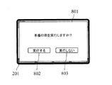
図8は、複合機が試し印刷処理を終了した際にディスプレイに表示する表示画面の一例を示す図である。この例では、表示画面801には、「本番印刷を実行しますか?」というメッセージが示されている。また、表示画面801は、印刷条件設定部402による問い合わせの回答に使用する回答ボタン802、803を備える。ユーザが「実行しない」ボタン803を選択した場合、印刷条件設定部402は設定履歴記憶部407に履歴の消去を指示し、履歴の消去が完了すると手順が終了する(ステップS509No、S512)。
FIG. 8 is a diagram illustrating an example of a display screen that is displayed on the display when the multifunction peripheral finishes the trial printing process. In this example, the
一方、ユーザが「実行する」ボタン802を選択した場合、印刷条件設定部402は、識別子入力部(設定入力部401)を通じて識別子の入力をユーザに要求する(ステップS509Yes)。本実施形態では、印刷条件設定部402は、操作パネル200のディスプレイ201を介して当該要求を行う。
On the other hand, when the user selects the “execute”
図9は、本番印刷開始時に複合機がディスプレイに表示する表示画面の一例を示す図である。この例では、表示画面901には、「試し印刷条件IDを入力してください」というメッセージが示されている。また、表示画面901は、印刷条件設定部402による要求の回答に使用する入力欄902、先の画面での選択をキャンセルする際に使用する「終了」ボタン903を備える。ユーザが入力欄902に、テンキー210等の入力手段を使用して試し印刷条件IDを入力すると、印刷条件設定部402は入力された試し印刷条件IDにより特定される印刷条件を設定履歴記憶部407から読み出して保持する(ステップS510)。印刷条件を読み出した印刷条件設定部402は印刷実行部406にその旨を通知する。当該通知を受けた印刷実行部406は、印刷対象の全画像データを、印刷条件設定部402に保持された印刷条件で画像形成部140に印刷させる(ステップS511)。ここで、印刷対象の全画像データは、HDD304に格納されている画像データから選択したり、原稿搬送装置110の原稿トレイ111に原稿束をセットし、画像読取部120で新たに読み取ったりすることにより指定すればよい。
FIG. 9 is a diagram illustrating an example of a display screen that the multi-function peripheral displays on the display at the start of actual printing. In this example, the
なお、本実施形態では、印刷条件設定部402が、ID生成部403が生成した識別子と印刷条件とを関連づけて設定履歴記憶部407に記録する構成を採用しているため、入力された試し印刷条件IDにより特定される印刷条件を印刷条件設定部402が設定履歴記憶部407から読み出す構成になっている。しかしながら、試し印刷条件IDとして、印刷条件を構成する各項目の設定内容を一意に特定する識別子を採用している場合には、試し印刷条件IDから印刷条件を抽出するID解析部を設け、当該ID解析部が抽出した印刷条件が印刷条件設定部402に登録される構成を採用することも可能である。
In the present embodiment, the print
上述のようにして本番印刷を実行した印刷実行部406は、印刷条件設定部402にその旨を通知する。当該通知を受けた印刷条件設定部402は、設定履歴記憶部407に履歴の消去を指示し、履歴の消去が完了すると手順が終了する(ステップS512)。
The
なお、表示画面901において、ユーザが「終了」ボタン903を選択した場合は、ステップS509において、本番印刷を実行しない場合と同様の手順が実行される。
If the user selects the “END”
以上のように、この複合機では、試し印刷において選択した印刷条件を示す識別子を入力するだけで、その印刷条件を画像形成装置に設定することができる。また、当該印刷条件で本番印刷を実施することができる。したがって、最適な印刷条件を選択するための作業効率が従来に比べて向上する。 As described above, in this multi-function peripheral, the print condition can be set in the image forming apparatus only by inputting the identifier indicating the print condition selected in the trial printing. In addition, actual printing can be performed under the printing conditions. Therefore, the work efficiency for selecting the optimum printing conditions is improved as compared with the conventional case.
なお、上記では、特に好ましい実施形態として、識別子入力部を備え、識別子入力部を通じて入力された識別子により特定される印刷条件を印刷条件設定部に保持させる構成を説明したが、識別子入力部は本発明に必須の要素ではない。例えば、印刷条件設定部402が、一連の試し印刷処理において実行された全試し印刷条件IDを設定履歴記憶部407から読み出してディスプレイ表示し、ユーザに、所望の状態で印刷された印刷物に印刷された試し印刷条件IDを選択させる構成を採用することもできる。この場合、印刷条件設定部402は、ユーザが選択した試し印刷条件IDにより特定される印刷条件を設定履歴記憶部407から読み出し、当該印刷条件で本番印刷を実行することになる。
In the above description, a configuration in which an identifier input unit is provided and the print condition specified by the identifier input through the identifier input unit is held in the print condition setting unit is described as a particularly preferable embodiment. It is not an essential element for the invention. For example, the print
以上説明したように、本発明によれば、ユーザが印刷条件を順次変更して試し印刷をする際に、同一の印刷条件で試し印刷が実行されるのを防止することができる。その結果、用紙やトナーが無駄な消費を抑制できる。また、試し印刷において選択した印刷条件を示す識別子を入力するだけで、その印刷条件を画像形成装置に設定することができる。したがって、極めて容易に、その印刷条件で本番印刷を実施することができる。 As described above, according to the present invention, it is possible to prevent the trial printing from being executed under the same printing conditions when the user performs the trial printing by sequentially changing the printing conditions. As a result, wasteful consumption of paper and toner can be suppressed. Also, simply by inputting an identifier indicating the printing condition selected in the trial printing, the printing condition can be set in the image forming apparatus. Therefore, it is very easy to perform the actual printing under the printing conditions.
なお、上述した各実施形態は本発明の技術的範囲を制限するものではなく、既に記載したもの以外でも、本発明の範囲内で種々の変形や応用が可能である。例えば、設定履歴記憶部、印刷条件比較部、報知部を備えない構成を採用してもよい。この構成であっても、印刷条件を特定する識別子を試し印刷対象の画像データとともに用紙上に印刷することができる。すなわち、複数の異なる印刷条件を適用して試し印刷を実施した場合であっても、生成された複数の印刷物の中から所望の印刷物を選択するだけで、選択した用紙に印刷された識別子によってその印刷条件を速やかに特定することができ、最適な印刷条件を選択するための作業効率が向上するという効果を得ることができる。 The above-described embodiments do not limit the technical scope of the present invention, and various modifications and applications other than those already described are possible within the scope of the present invention. For example, a configuration that does not include the setting history storage unit, the print condition comparison unit, and the notification unit may be employed. Even with this configuration, it is possible to print the identifier for specifying the printing condition on the paper together with the image data to be subjected to trial printing. That is, even when trial printing is performed by applying a plurality of different printing conditions, simply selecting a desired printed material from a plurality of generated printed materials, and the identifier is printed on the selected paper. It is possible to quickly specify the printing conditions, and to obtain an effect that the work efficiency for selecting the optimum printing conditions is improved.
また、上述の実施形態では、デジタル複合機として本発明を具体化したが、デジタル複合機に限らず、試し印刷機能を有するプリンタや複写機などの画像印刷装置に本発明を適用することも可能である。 In the above-described embodiment, the present invention is embodied as a digital multifunction peripheral. However, the present invention can be applied not only to a digital multifunction peripheral but also to an image printing apparatus such as a printer or a copying machine having a test printing function. It is.
本発明によれば、試し印刷を通じて印刷条件を選択する際に、効率良く最適な印刷条件を確認することができ、画像印刷装置として有用である。 According to the present invention, when selecting printing conditions through trial printing, the optimum printing conditions can be confirmed efficiently, which is useful as an image printing apparatus.
100 複合機
110 原稿搬送装置
120 画像読取部
130 画像形成部
200 操作パネル
401 設定入力部(兼 識別子入力部)
402 印刷条件設定部
403 ID生成部
404 画像データ合成部
405 画像データ保持部
406 印刷実行部
407 設定履歴記憶部
408 印刷条件比較部
409 報知部
701 メッセージ(警告表示)
DESCRIPTION OF
402 Print
Claims (3)
画像データを用紙上に印刷する画像形成部と、
前記画像形成部における画像データの印刷に適用される印刷条件が保持される印刷条件設定部と、
前記印刷条件設定部に印刷条件を登録する設定入力部と、
前記印刷条件設定部に保持された印刷条件を特定する識別子を生成するID生成部と、
試し印刷対象の画像データと前記ID生成部が生成した識別子とを合成し、当該画像データが印刷される用紙の所定位置に識別子を配置した、試し印刷用画像データを生成する画像データ合成部と、
前記画像データ合成部が生成した前記試し印刷用画像データを、前記印刷条件設定部に保持された印刷条件で前記画像形成部に印刷させる印刷実行部と、
一連の試し印刷において、前記印刷条件設定部に保持され、試し印刷が実行された印刷条件の履歴を記憶する設定履歴記憶部と、
前記一連の試し印刷において、前記印刷条件設定部に新たに保持された印刷条件と、前記設定履歴記憶部に記憶された印刷条件とを比較する印刷条件比較部と、
前記設定履歴記憶部に記憶された印刷条件に、前記印刷条件設定部に新たに保持された印刷条件と一致する印刷条件が含まれている場合、警告を発報する報知部と、
を備える画像印刷装置。 An image printing apparatus having a test printing function,
An image forming unit that prints image data on paper;
A printing condition setting unit that holds printing conditions applied to printing of image data in the image forming unit;
A setting input unit for registering printing conditions in the printing condition setting unit;
An ID generation unit that generates an identifier for specifying the printing condition held in the printing condition setting unit;
An image data synthesizing unit for synthesizing the image data to be tested and the identifier generated by the ID generation unit, and generating the image data for test printing, wherein the identifier is arranged at a predetermined position on a sheet on which the image data is printed; ,
A print execution unit that causes the image forming unit to print the test print image data generated by the image data synthesis unit under a print condition held in the print condition setting unit;
In a series of trial printing, a setting history storage unit that stores a history of printing conditions that are held in the printing condition setting unit and the trial printing is executed;
In the series of test printing, a printing condition comparison unit that compares the printing condition newly held in the printing condition setting unit with the printing condition stored in the setting history storage unit;
A notification unit that issues a warning when the printing condition stored in the setting history storage unit includes a printing condition that matches the printing condition newly held in the printing condition setting unit;
An image printing apparatus comprising:
前記問い合わせに応じてユーザが印刷する旨を回答した場合、前記画像データ合成部は、前記試し印刷対象の画像データと前記警告の対象となった印刷条件について先に前記ID生成部が生成した識別子とを合成した前記試し印刷用画像データを生成する、請求項1記載の画像印刷装置。 The notifying unit inquires of the user whether or not to execute printing under the printing condition that is the target of the warning together with the warning,
When the user replies to the print in response to the inquiry, the image data composition unit generates the identifier generated by the ID generation unit in advance for the test print target image data and the print condition for the warning. The image printing apparatus according to claim 1, wherein the image data for test printing is generated by combining .
前記印刷実行部が、入力された識別子により特定される印刷条件で印刷対象の全画像データを前記画像形成部に印刷させる、請求項1または請求項2記載の画像印刷装置。 An identifier input unit for inputting an identifier printed at a predetermined position on the paper;
The image printing apparatus according to claim 1, wherein the print execution unit causes the image forming unit to print all image data to be printed under a printing condition specified by the input identifier.
Priority Applications (1)
| Application Number | Priority Date | Filing Date | Title |
|---|---|---|---|
| JP2009247849A JP5389605B2 (en) | 2009-10-28 | 2009-10-28 | Image printing device |
Applications Claiming Priority (1)
| Application Number | Priority Date | Filing Date | Title |
|---|---|---|---|
| JP2009247849A JP5389605B2 (en) | 2009-10-28 | 2009-10-28 | Image printing device |
Publications (2)
| Publication Number | Publication Date |
|---|---|
| JP2011093147A JP2011093147A (en) | 2011-05-12 |
| JP5389605B2 true JP5389605B2 (en) | 2014-01-15 |
Family
ID=44110623
Family Applications (1)
| Application Number | Title | Priority Date | Filing Date |
|---|---|---|---|
| JP2009247849A Expired - Fee Related JP5389605B2 (en) | 2009-10-28 | 2009-10-28 | Image printing device |
Country Status (1)
| Country | Link |
|---|---|
| JP (1) | JP5389605B2 (en) |
Families Citing this family (6)
| Publication number | Priority date | Publication date | Assignee | Title |
|---|---|---|---|---|
| US8971734B2 (en) | 2011-03-29 | 2015-03-03 | Canon Kabushiki Kaisha | Image forming apparatus |
| WO2012137972A1 (en) | 2011-04-06 | 2012-10-11 | Canon Kabushiki Kaisha | Image forming apparatus |
| CN103172876A (en) * | 2011-12-26 | 2013-06-26 | 东丽纤维研究所(中国)有限公司 | Polylactic acid microsphere and preparation method thereof |
| JP6264933B2 (en) * | 2014-02-20 | 2018-01-24 | コニカミノルタ株式会社 | Image forming apparatus, image forming system, and image forming control program |
| JP2017123642A (en) * | 2016-01-06 | 2017-07-13 | 株式会社リコー | Image forming apparatus and program |
| JP6610897B2 (en) * | 2016-12-02 | 2019-11-27 | 京セラドキュメントソリューションズ株式会社 | Image forming apparatus and program |
Family Cites Families (6)
| Publication number | Priority date | Publication date | Assignee | Title |
|---|---|---|---|---|
| JP2000238382A (en) * | 1999-02-19 | 2000-09-05 | Hitachi Koki Co Ltd | Print page management system |
| JP2000242448A (en) * | 1999-02-19 | 2000-09-08 | Hitachi Koki Co Ltd | Printer print parameter registration system |
| JP2003005938A (en) * | 2001-06-25 | 2003-01-10 | Canon Inc | IMAGE OUTPUT SYSTEM, IMAGE OUTPUT METHOD, INFORMATION PROCESSING DEVICE, ITS CONTROL METHOD, STORAGE MEDIUM STORING ITS PROGRAM, AND ITS PROGRAM |
| JP2005328257A (en) * | 2004-05-13 | 2005-11-24 | Kyocera Mita Corp | Image forming apparatus and printing program |
| JP4218708B2 (en) * | 2006-07-20 | 2009-02-04 | コニカミノルタビジネステクノロジーズ株式会社 | Control program for controlling image forming apparatus |
| JP2008059034A (en) * | 2006-08-29 | 2008-03-13 | Fuji Xerox Co Ltd | Printer and program |
-
2009
- 2009-10-28 JP JP2009247849A patent/JP5389605B2/en not_active Expired - Fee Related
Also Published As
| Publication number | Publication date |
|---|---|
| JP2011093147A (en) | 2011-05-12 |
Similar Documents
| Publication | Publication Date | Title |
|---|---|---|
| JP5389605B2 (en) | Image printing device | |
| US7933526B2 (en) | Image forming apparatus and image forming method with forms for printing according to consumable material | |
| JP2012049855A (en) | Image formation device and image formation system | |
| JP2010271546A (en) | Image forming apparatus, control method therefor, and program | |
| JP5661573B2 (en) | Image forming apparatus and image forming system | |
| JP6222242B2 (en) | Image processing apparatus and image processing system | |
| JP5420494B2 (en) | Guidance providing apparatus and electronic device | |
| JP5069768B2 (en) | Operating device and electronic device | |
| JP5868893B2 (en) | Image processing device | |
| US10834277B2 (en) | Image forming apparatus including job end notification function and control method thereof | |
| JP2008246812A (en) | Image forming system | |
| JP5389606B2 (en) | Image printing device | |
| JP2013162456A (en) | Image forming apparatus and control method | |
| JP5705787B2 (en) | Authentication apparatus and image forming apparatus | |
| JP5474911B2 (en) | Operating device and image processing device | |
| JP2011176606A (en) | Help display device, image forming apparatus, and help display system | |
| JP5889848B2 (en) | Information processing terminal, printing program, printing apparatus and printing system | |
| JP6169220B2 (en) | Authentication apparatus and image forming apparatus | |
| JP5112470B2 (en) | Help display device and electronic device | |
| JP6054494B2 (en) | Operating device and electronic device | |
| JP6017607B2 (en) | Authentication apparatus and image forming apparatus | |
| JP6198209B2 (en) | SETTING DEVICE, IMAGE FORMING DEVICE HAVING THE SETTING DEVICE, AND CLEAR COAT SETTING METHOD | |
| JP2011097412A (en) | Image reading apparatus | |
| JP5528974B2 (en) | Image printing apparatus and image printing system | |
| JP2007078726A (en) | Image forming apparatus |
Legal Events
| Date | Code | Title | Description |
|---|---|---|---|
| A621 | Written request for application examination |
Free format text: JAPANESE INTERMEDIATE CODE: A621 Effective date: 20111121 |
|
| A131 | Notification of reasons for refusal |
Free format text: JAPANESE INTERMEDIATE CODE: A131 Effective date: 20130313 |
|
| A977 | Report on retrieval |
Free format text: JAPANESE INTERMEDIATE CODE: A971007 Effective date: 20130313 |
|
| A521 | Request for written amendment filed |
Free format text: JAPANESE INTERMEDIATE CODE: A523 Effective date: 20130508 |
|
| TRDD | Decision of grant or rejection written | ||
| A01 | Written decision to grant a patent or to grant a registration (utility model) |
Free format text: JAPANESE INTERMEDIATE CODE: A01 Effective date: 20130911 |
|
| A61 | First payment of annual fees (during grant procedure) |
Free format text: JAPANESE INTERMEDIATE CODE: A61 Effective date: 20131009 |
|
| R150 | Certificate of patent or registration of utility model |
Ref document number: 5389605 Country of ref document: JP Free format text: JAPANESE INTERMEDIATE CODE: R150 Free format text: JAPANESE INTERMEDIATE CODE: R150 |
|
| LAPS | Cancellation because of no payment of annual fees |