JP5388823B2 - Trajectory measuring device - Google Patents
Trajectory measuring device Download PDFInfo
- Publication number
- JP5388823B2 JP5388823B2 JP2009274745A JP2009274745A JP5388823B2 JP 5388823 B2 JP5388823 B2 JP 5388823B2 JP 2009274745 A JP2009274745 A JP 2009274745A JP 2009274745 A JP2009274745 A JP 2009274745A JP 5388823 B2 JP5388823 B2 JP 5388823B2
- Authority
- JP
- Japan
- Prior art keywords
- machine
- acceleration
- error
- trajectory
- detected
- Prior art date
- Legal status (The legal status is an assumption and is not a legal conclusion. Google has not performed a legal analysis and makes no representation as to the accuracy of the status listed.)
- Active
Links
Images


Landscapes
- Machine Tool Sensing Apparatuses (AREA)
- Numerical Control (AREA)
- Control Of Position Or Direction (AREA)
Description
本発明は、数値制御工作機械やロボットなどの運動軌跡を測定する軌跡測定装置に関する。 The present invention relates to a trajectory measuring apparatus that measures a motion trajectory of a numerically controlled machine tool, a robot, or the like.
数値制御工作機械やロボットでは、モータを駆動して指令位置にできる限り忠実に機械の可動軸の位置を制御する。その場合、機械の振動や運動方向反転時の摩擦力の影響により指令位置と実際の機械位置との間に誤差が生じ、例えば加工面に傷が付いたりする。そのような問題が発生した場合には、機械の運動軌跡を測定して問題の原因を探り、モータを制御するコントローラの各種パラメータを調整することが行われる。そのための機械運動軌跡の測定表示方法としては、複数の方法が公知である。 In numerically controlled machine tools and robots, the position of the movable shaft of the machine is controlled as faithfully as possible by driving the motor to the command position. In that case, an error occurs between the command position and the actual machine position due to the influence of the vibration of the machine or the frictional force at the time of reversing the movement direction. When such a problem occurs, the movement locus of the machine is measured to find the cause of the problem, and various parameters of the controller that controls the motor are adjusted. For this purpose, a plurality of methods are known for measuring and displaying the machine motion trajectory.
特許文献1に示された方法は、2つの高精度な鋼球の間が変位計を介して結合され、2球間の相対距離を一定に保つような運動(円弧)を行わせたときの変位を読み取るものである。この方法はボールバー法と呼ばれ、広く普及している。
In the method disclosed in
非特許文献1には、交差格子スケール(グリッドエンコーダ)と呼ばれる測定器を使って工作機械の運動軌跡を測定する方法が示されている。交差格子スケールを用いた測定では、直角に交差した2つの光学格子をガラス基板上に有するスケールと、スケールの光学格子のそれぞれに対応して互いに直角に交差して配設された2つの受光部を有する検出ヘッドとを用い、2次元的な相対変位の測定が可能である。
特許文献2には、工作機械を円運動させたときのフィードバックされた位置信号から、円弧軌跡を算出して目標軌跡との誤差を拡大して表示する方法が示されている。
Non-Patent
しかしながら、特許文献1に記載の方法では、決められた半径の円弧軌跡しか測定できないという問題があるほか、ケーブルが絡まりやすく、高速運動の測定は難しかった。また、ケーブルの取り回しやボールバーの取り外しのために、常に1名以上のオペレータが必要となっていた。
However, the method described in
非特許文献1に記載の交差格子スケールを用いた精度測定方法では、自由な形状や高速運動の測定ができるものの、スケールとヘッドとの間隔を0.5mm程度に保つ必要があり、スケールとヘッドが衝突して破損しやすいという問題があった。また、3次元的な運動軌跡は測定できなかった。
Although the accuracy measurement method using the crossed grid scale described in
また、上記の方法に共通して、機械に変位計を取付けて運動軌跡を測定するために、例えば、工作機械にジグや工具が取り付けてある場合には、測定のためにそれらを外す必要があった。そのため、実際の使用状態にある機械の運動軌跡を測定できないという問題があった。 Also, in common with the above method, in order to measure the movement trajectory by attaching a displacement meter to the machine, for example, when a jig or tool is attached to the machine tool, it is necessary to remove them for measurement. there were. For this reason, there has been a problem that it is impossible to measure the motion trajectory of a machine in actual use.
さらに、上記の方法に共通して、測定範囲が比較的狭い範囲に限られているために、誤って測定範囲を超えて機械が運動した場合には、測定器が破損する。また、ストロークの大きな機械の運動軌跡を測定しようとすると、測定器を一旦取り外して場所をずらして設置し直す必要があった。また、測定器を設置できない機械も存在し、そのような場合には測定ができなかった。 Furthermore, since the measurement range is limited to a relatively narrow range in common with the above method, the measuring instrument is damaged if the machine moves accidentally beyond the measurement range. In addition, when attempting to measure the motion trajectory of a machine having a large stroke, it was necessary to remove the measuring device once and shift the location. In addition, there are machines that cannot install a measuring instrument, and in such a case, measurement could not be performed.
特許文献2に記載の方法では、機械に測定器を設置せずに、フィードバック信号から求めた機械位置により運動軌跡を算出するため、自由形状かつ全可動範囲内での測定が可能であり、測定器が破損することもない。しかし、実際の機械位置とフィードバック位置とが同じであるとは限らず、例えば機械に振動が発生している場合やバックラッシが存在する場合には、機械の運動軌跡を正しく評価することができないという問題があった。
In the method described in
本発明は、上記に鑑みてなされたものであって、実際の使用状態にある機械の運動軌跡をジグや工具を外すことなく精度よく測定することが可能な軌跡測定装置を得ることを目的とする。 The present invention has been made in view of the above, and an object of the present invention is to provide a trajectory measuring apparatus capable of accurately measuring a motion trajectory of a machine in actual use without removing a jig or a tool. To do.
上述した課題を解決し、目的を達成するために、本発明の軌跡測定装置は、可動軸を駆動するモータの検出位置が指令位置に追従するように機械位置が制御される機械の運動軌跡を測定する軌跡測定装置であって、前記機械の加速度を測定する加速度計と、前記指令位置または前記検出位置ないしはその両方と前記加速度に基づいて前記機械の運動軌跡を解析する運動軌跡解析部とを備えることを特徴とする。 In order to solve the above-described problems and achieve the object, the trajectory measurement apparatus of the present invention is configured to obtain a motion trajectory of a machine whose machine position is controlled so that a detection position of a motor driving a movable shaft follows a command position. A trajectory measuring apparatus for measuring, comprising: an accelerometer that measures the acceleration of the machine; and a motion trajectory analysis unit that analyzes the motion trajectory of the machine based on the command position and / or the detection position and the acceleration. It is characterized by providing.
この発明によれば、実際の使用状態にある機械の運動軌跡をジグや工具を外すことなく精度よく測定することが可能という効果を奏する。 According to the present invention, there is an effect that it is possible to accurately measure the motion trajectory of a machine in an actual use state without removing a jig or a tool.
以下に、本発明に係る軌跡測定装置の実施の形態を図面に基づいて詳細に説明する。なお、この実施の形態によりこの発明が限定されるものではない。 Embodiments of a trajectory measuring apparatus according to the present invention will be described below in detail with reference to the drawings. Note that the present invention is not limited to the embodiments.
実施の形態1.
図1は、本発明に係る軌跡測定装置が適用される数値制御工作機械の実施の形態1の概略構成を示す斜視図である。図1において、X軸、Y軸およびZ軸方向に運動を案内された複数の可動軸を有し、各可動軸はモータ1x、1y、1zと送りねじ2x、2y、2zから成る駆動機構によって駆動される。モータ1x、1y、1zの回転角度は回転角度検出器3x、3y、3zによりそれぞれ検出され、モータ制御装置にフィードバックされる。モータ駆動方法として、モータ1x、1y、1zと送りねじ2x、2y、2zの代わりにリニアモータを用い、回転角度検出器3x、3y、3zの代わりにリニアスケールを用いる場合もある。
FIG. 1 is a perspective view showing a schematic configuration of a first embodiment of a numerically controlled machine tool to which a trajectory measuring apparatus according to the present invention is applied. In FIG. 1, it has a plurality of movable shafts guided in motion in the X-axis, Y-axis, and Z-axis directions, and each movable shaft is driven by a drive
この数値制御工作機械では、Y軸の駆動機構によりワークテーブル4が駆動され、X軸の駆動機構によりコラム5が駆動される。コラム5に取付けられたZ軸の駆動機構により、ラム6を介して主軸頭7が駆動され、結果として主軸頭7の先端に取付けられる工具と、ワークテーブル4上に設置される工作物との間に3次元形状が創成される。なお、ワークテーブル4およびコラム5は架台21上に設置される。
In this numerically controlled machine tool, the work table 4 is driven by the Y-axis drive mechanism, and the column 5 is driven by the X-axis drive mechanism. The spindle head 7 is driven via the
図2は、図1の数値制御工作機械の駆動機構の概略構成を示す側面図である。なお、図2の例では、便宜上Y軸の駆動機構のみ示しているが、X軸およびZ軸の駆動機構についても同一である。図2において、モータ1yの回転運動はカップリング8yを介して送りねじ2yに伝達され、ナット9yを介して直進運動に変換される。送りねじ2yの直進運動は、サポートベアリング10yにより拘束されている。
FIG. 2 is a side view showing a schematic configuration of the drive mechanism of the numerically controlled machine tool of FIG. In the example of FIG. 2, only the Y-axis drive mechanism is shown for convenience, but the same applies to the X-axis and Z-axis drive mechanisms. In FIG. 2, the rotational motion of the
モータ制御装置の指令生成部11から出力される指令位置はモータ駆動部12に伝送され、モータ駆動部12では指令位置と回転角度検出器3yにより検出されたモータ1yの回転角度を位置に変換した検出位置との誤差ができる限り小さくなるようにモータ1yを駆動する。なお、指令位置および検出位置とは、それぞれ各可動軸がもつ基準原点位置に対する変位を意味する。
The command position output from the
モータ1yの回転角度に加えて、ワークテーブル4の位置を検出するリニアスケールやレーザ変位計を付加し、モータ駆動部12にフィードバックする場合もあるし、さらにモータ1yと送りねじ2yの代わりにリニアモータを用いる場合もある。
数値制御工作機械においては、主軸頭7の先端に取付けられる工具とワークテーブル4との相対変位が重要であり、相対変位を予め測定して、指令生成部11またはモータ駆動部12において機械に存在する誤差を補正することが一般的に行われている。誤差の原因として、可動軸間の直角度や送りねじ2yのピッチ誤差といった静的な誤差があり、これらは機械を組立てる段階で測定および調整が行われ、通常使用中に変化することは少ない。
In addition to the rotation angle of the
In a numerically controlled machine tool, the relative displacement between the tool attached to the tip of the spindle head 7 and the work table 4 is important. The relative displacement is measured in advance, and the
一方、主にカップリング8yや送りねじ2y、サポートベアリング10y部分で生じる弾性変形および振動や、コラム5やラム6の姿勢変化や振動、また摩擦力による誤差が生じることも知られており、これらの動的な誤差は、機械の使用状況やワークテーブル4上の負荷質量、機械の経年変化や摩耗等によって特性が変化する。そこで、機械を使用中にも定期的または継続的に機械運動軌跡を測定し、モータ制御装置の各種補正パラメータを調整できることが望ましい。
On the other hand, it is also known that elastic deformation and vibration mainly generated in the
図3は、本発明に係る軌跡測定装置が適用された数値制御工作機械の実施の形態1の概略構成を示すブロック図である。図3において、この軌跡測定装置では、モータ制御装置のパラメータを調整するために必要な運動軌跡情報が測定される。なお、運動軌跡情報は、モータ制御装置の調整に必要とされる情報を含むことであり、具体的には、機械振動の有無、振動の周期や振幅、象限切り替え時に生じる突起状の軌跡誤差(象限突起)の高さや幅、およびバックラッシやロストモーションの大きさなどの情報である。 FIG. 3 is a block diagram showing a schematic configuration of the first embodiment of the numerically controlled machine tool to which the trajectory measuring apparatus according to the present invention is applied. In FIG. 3, the trajectory measuring apparatus measures motion trajectory information necessary for adjusting the parameters of the motor control apparatus. The movement trajectory information includes information necessary for adjustment of the motor control device. Specifically, the presence or absence of mechanical vibration, the period and amplitude of vibration, and a protruding trajectory error ( Information such as the height and width of the quadrant projections, and the size of backlash and lost motion.
ここで、ワークテーブル4上には工作物17が設置され、主軸頭7の先端には工具16が取り付けられている。そして、軌跡測定装置には、機械の加速度aを測定する加速度計13a、13bおよび指令位置Piまたは検出位置Pdないしはその両方と加速度aに基づいて機械の運動軌跡を解析する運動軌跡解析部14が設けられている。また、運動軌跡解析部14にて解析された機械の運動軌跡を表示する運動軌跡表示部15を設けるようにしてもよい。
Here, a
運動軌跡解析部14には、加速度aの積分結果に基づいて機械位置Pkを算出する加速度積分部14aと、指令位置Piまたは検出位置Pdないしはその両方に基づいて、機械位置Pkを補正する誤差補正部14bが設けられている。誤差補正部14bは、機械位置Pkと、検出位置Pdないしは指令位置Piから推定される位置とを比較することで、加速度aの測定誤差と積分誤差を分離して機械位置Pkを補正することができる。
The motion
そして、指令生成部11では入力された目標位置Pmを解析して指令位置Piを生成する。モータ駆動部12では、入力された指令位置Piと回転角度検出器3x、3y、3zから伝送される検出信号Sdを処理して得られる検出位置Pdとができる限り一致するようにモータ駆動電圧Vmを出力してモータ1x、1y、1zを駆動する。
Then, the
また、運動軌跡解析部14には、加速度a、目標位置Pm、指令位置Piおよび検出位置Pdが入力される。そして、加速度aを2回積分することで機械位置Pkが算出され、指令位置Piまたは検出位置Pdないしはその両方に基づいて機械位置Pkが補正され、補正後の機械位置Pk´が指令位置Piおよび検出位置Pdとともに運動軌跡表示部15に送られる。
Further, the acceleration a, the target position Pm, the command position Pi, and the detection position Pd are input to the motion
なお、加速度aを2回積分して位置を算出する方法は、例えば慣性航法装置や建築物などの振動測定にも使われている。ただし、その測定精度は、前者で数m、後者で数十mmであることが知られており、数値制御工作機械の測定において要求される精度と比べて4〜6桁悪い。加速度aを2回積分して位置を算出する場合、加速度aの測定誤差および積分誤差が発生する。 Note that the method of calculating the position by integrating the acceleration a twice is also used for vibration measurement of, for example, an inertial navigation system or a building. However, the measurement accuracy is known to be several meters in the former and several tens of millimeters in the latter, which is 4 to 6 orders of magnitude worse than the accuracy required in the measurement of numerically controlled machine tools. When the position is calculated by integrating the acceleration a twice, the measurement error and the integration error of the acceleration a occur.
加速度aの測定誤差の原因として、加速度計13a、13bの設置誤差がある。この設置誤差は、加速度計13a、13bの感度方向が、測定対象とする可動軸の方向に対して偏向していることであり、測定対象の可動軸以外の可動軸の運動による影響を受けることになる。このような場合には、測定対象とした可動軸以外の可動軸が加速度aの測定結果ないしは加速度aを2回積分して求めた機械位置に及ぼす影響を解析的または数値的に求め、求めた誤差分だけ加速度aまたは機械位置Pkを補正することができる。
As a cause of the measurement error of the acceleration a, there is an installation error of the
図4は、本発明に係る軌跡測定装置に適用される加速度計の設置誤差を示す側面図である。図4において、感度方向が直交するように固定された2つのX軸加速度計18およびY軸加速度計19を使ってXYテーブルのX軸およびY軸方向の加速度を測定する際、X軸加速度計18およびY軸加速度計19がZ軸まわりに角度θだけ傾いて設置されていたとすると、真の加速度ax、ayと検出される加速度ax´、ay´との関係は(1)式のように表される。このため、X軸加速度計18およびY軸加速度計19の感度方向の傾き角θから真の加速度ax、ayを算出し、検出される加速度ax´、ay´を補正できる。
FIG. 4 is a side view showing an installation error of the accelerometer applied to the trajectory measuring apparatus according to the present invention. In FIG. 4, when measuring the acceleration in the X-axis and Y-axis directions of the XY table using two

また、例えばXYテーブルのX軸のみを運動させた場合に検出される加速度と、Y軸のみを運動させた場合に検出される加速度とから、測定対象とした可動軸以外の可動軸の運動による影響を予め同定しておき、その結果を使って加速度計の設置誤差による影響を補正することもできる。 Further, for example, from the acceleration detected when only the X axis of the XY table is moved and the acceleration detected when only the Y axis is moved, the movement is caused by the movement of a movable axis other than the movable axis to be measured. The influence can be identified in advance, and the result can be used to correct the influence due to the installation error of the accelerometer.
加速度aの数値積分を行う際に生じる積分誤差は、積分誤差が機械位置Pkに及ぼす影響を指令位置Piから解析的または数値的に求め、求めた誤差分だけ機械位置Pkを補正することができる。 The integration error that occurs when performing the numerical integration of the acceleration a can analytically or numerically determine the influence of the integration error on the machine position Pk from the command position Pi, and correct the machine position Pk by the calculated error. .
例えば、2つの可動軸を同時に動かして円運動を行う場合には、各軸の運動は正弦波および余弦波となる。そのときの加速度波形を台形公式により2回数値積分して位置を求めた場合の積分誤差を含む誤差波形Epは、解析的に(2)式のように求められる。ただし、(2)式において、Rは円運動の半径、Fは送り速度であり、Δtはデータの時間間隔である。 For example, when performing circular motion by moving two movable shafts simultaneously, the motion of each shaft is a sine wave and a cosine wave. Error waveform E p comprising integral error when the acceleration waveform to determine the position by integrating 2 frequency value by trapezoidal rule at that time is obtained as analytically (2). In equation (2), R is the radius of circular motion, F is the feed rate, and Δt is the data time interval.
実際には、加速度aの測定誤差と積分誤差を別々に計算して補正することが難しい場合が多い。そこで、加速度計13a、13bの設置誤差および積分誤差の両方が存在した場合に生じる誤差波形を複数のパラメータをもつ数式として指令位置Piから求めるとともに、加速度aを2回積分して求めた機械位置Pkと、検出位置Pdまたは指令位置Piから推定される機械位置との差を、(2)式で近似することで、加速度計13a、13bの設置誤差および積分誤差を同定し、同定された誤差分だけ機械位置Pkを補正することができる。
In practice, it is often difficult to calculate and correct the measurement error and integration error of acceleration a separately. Accordingly, an error waveform generated when both the installation error and the integration error of the
例えば、円運動を行った場合の加速度aを2回積分して機械位置Pkを求めた場合において、加速度計13a、13bの設置誤差と積分誤差を含む誤差波形Epは円運動と同じ周期を持つ正弦波になり、(3)式のようなn次多項式に帰着させることができる。 For example, in the case of obtaining the machine position Pk and the acceleration a is integrated twice in the case of performing circular motion, accelerometer 13a, the error waveform E p is the same period as the circular motion including installation error and the integral error of 13b It becomes a sine wave, and can be reduced to an nth order polynomial as shown in equation (3).
図5は、図3の運動軌跡解析部14の概略構成を示すブロック図である。図5において、運動軌跡解析部14には、加速度積分部14aおよび誤差補正部14bが設けられ、誤差補正部14bには、減算器K1、K2および誤差波形近似部23が設けられている。
FIG. 5 is a block diagram showing a schematic configuration of the motion
そして、加速度aを2回積分して得た機械位置Pkに含まれる加速度計13a、13bの設置誤差と積分誤差を同定して補正する場合、減算器K1において、加速度aを2回積分して得た機械位置Pkと、フィードバックされた検出位置Pd(FBデータ)との差を算出する。ここには、機械がもつ誤差要因に起因する誤差と加速度計13a、13bの設置誤差や積分誤差に起因する誤差の両方が含まれている。
When the installation error and integration error of the
このうち、加速度計13a、13bの設置誤差や積分誤差に起因する誤差成分は(3)式の多項式で近似できるので、加速度aを2回積分して得た機械位置Pkと、フィードバックされた検出位置Pd(FBデータ)との差のうち、多項式近似できる成分は加速度計13a、13bの設置誤差や積分誤差に起因する誤差であることになる。よって、加速度aを2回積分して得た機械位置Pkとフィードバックされた検出位置Pd(FBデータ)との差を誤差波形近似部23にて多項式近似する。そして、減算器K2において、この多項式により得られる解を、加速度aを2回積分して得た機械位置Pkから差し引くことで、補正後の機械位置Pk´を求めることができる。
Among these, since the error component due to the installation error or integration error of the
なお、図5に示す実施例では検出位置Pd(FBデータ)を使って誤差を同定しているが、これを指令位置Piから推定される機械位置としてもよい。また、実施例では円運動を取り上げているが、他の運動を行った場合には、加速度aの設置誤差と積分誤差は(3)式とは異なっていてもよい。 In the embodiment shown in FIG. 5, the error is identified using the detection position Pd (FB data), but this may be a machine position estimated from the command position Pi. In addition, although circular motion is taken up in the embodiment, when other motion is performed, the installation error and the integration error of the acceleration a may be different from the equation (3).
誤差波形を近似する際には、例えば最小二乗法により近似式の未知パラメータを決定してもよいし、例えば滑降シンプレックス法のような数値解法を使ってもよい。 When approximating the error waveform, the unknown parameter of the approximate expression may be determined by, for example, the least square method, or a numerical solution method such as the downhill simplex method may be used.
図6は、図5の誤差波形近似部23で近似される誤差波形の近似多項式の次数と近似誤差との関係を表す図である。図6において、円運動を測定したときの誤差波形は(3)式の多項式で近似でき、その近似精度は多項式の次数によって変化する。図6からわかるように、近似誤差は多項式の次数が高いほど小さくなり、8次以上にすれば近似誤差は1μm以下になることがわかる。
FIG. 6 is a diagram showing the relationship between the order of the approximation polynomial of the error waveform approximated by the error
通常の工作機械を測定対象とする場合には、その測定精度に対する要求は1μm程度であるから、円運動を測定する場合には8次の多項式で誤差を近似して補正すれば、実用上十分な精度で機械運動軌跡を測定できることになる。 When measuring an ordinary machine tool, the measurement accuracy requirement is about 1 μm. Therefore, when measuring circular motion, it is practically sufficient to correct the error by approximating the error with an 8th order polynomial. The machine motion trajectory can be measured with high accuracy.
図7は、図3の軌跡測定装置にて測定された機械端軌跡およびモータ端軌跡を交差格子法(グリッドエンコーダ)による測定結果と比較して示す図である。なお、図7では、加速度計を使った測定方法を実際の工作機械に適用し、半径25mm、送り速度3000mm/minの円運動を測定した結果を示す。また、図7の例では、1divは10μmに相当する。図7(b)において、交差格子法では、機械端軌跡T4(実線)とモータ端軌跡T3(破線)との間に数マイクロメートルのずれが計測されている。また、図7(a)において、図3の軌跡測定装置においても、交差格子法と同様に、機械端軌跡T2(実線)とモータ端軌跡T1(破線)との間に数マイクロメートルのずれが計測できた。 FIG. 7 is a view showing the machine end locus and the motor end locus measured by the locus measuring apparatus of FIG. 3 in comparison with the measurement result by the cross grid method (grid encoder). FIG. 7 shows the result of measuring a circular motion with a radius of 25 mm and a feed rate of 3000 mm / min by applying a measurement method using an accelerometer to an actual machine tool. In the example of FIG. 7, 1 div corresponds to 10 μm. In FIG. 7B, in the cross grid method, a deviation of several micrometers is measured between the machine end locus T4 (solid line) and the motor end locus T3 (broken line). Further, in FIG. 7A, also in the trajectory measuring apparatus of FIG. 3, a deviation of several micrometers is present between the machine end trajectory T2 (solid line) and the motor end trajectory T1 (broken line), as in the crossed lattice method. I was able to measure.
なお、測定対象によっては工作機械ほどの測定精度がいらない場合もあり、そのような場合には、(3)式の近似多項式の次数を下げればよい。逆に、より高精度な測定が求められる場合には、(3)式の近似多項式の次数を上げることで、測定精度を調整できる。 Depending on the measurement target, the measurement accuracy as high as that of the machine tool may not be required. In such a case, the order of the approximate polynomial in the equation (3) may be lowered. On the other hand, when higher-precision measurement is required, the measurement accuracy can be adjusted by increasing the degree of the approximate polynomial in equation (3).
実施の形態2.
図5の構成では、測定対象である機械がもつ誤差要因に起因する誤差波形が、加速度計13a、13bの設置誤差および積分誤差により生じる誤差波形と同じ数式で表される場合には、本来測定対象である機械誤差も加速度計13a、13bの設置誤差や積分誤差と区別できずに取り除かれる。
In the configuration of FIG. 5, when the error waveform due to the error factor of the machine to be measured is expressed by the same equation as the error waveform caused by the installation error and integration error of the
そこで、加速度計13a、13bの設置誤差および積分誤差により生じる誤差波形が、測定対象である機械が持つ誤差要因に起因する誤差波形と同じ数式で表される場合には、指令位置Piまたは検出位置Pdから機械の誤差要因に起因する誤差量を推定して機械位置Pkに加算するようにしてもよい。
Therefore, when the error waveform caused by the installation error and the integration error of the
2つの可動軸を同時に制御する同時2軸制御運動である円運動を例にあげると、位置指令は正弦波往復運動となり、この時の加速度計13a、13bの設置誤差および積分誤差は、円運動と同じ周期を持つ正弦波状になることが解析的にわかっている。すなわち、円運動1周あたり1周期分の変動成分をもつ機械誤差については、加速度計13a、13bの設置誤差や積分誤差と区別できずに取り除かれる。
Taking circular motion, which is a simultaneous biaxial control motion that controls two movable axes simultaneously, for example, the position command is a sine wave reciprocating motion, and the installation error and integration error of the
図8(a)は、可動軸の駆動機構をモデル化して示すブロック図、図8(b)は、弾性変形による誤差の発生を説明する図である。図8(a)において、円運動1周あたり1周期分の変動成分をもつ機械誤差の一例として、機械の弾性変形に起因する誤差があげられる。例えば、可動軸の駆動機構を模式的にバネK(モータ端から機械端までの等価軸方向剛性)と質量M(被駆動体質量)として考えると、質量Mをある加速度aで加速した場合には加速度aと質量Mの積としての慣性力が作用する。慣性力が作用すると、慣性力と剛性の比として弾性変形が生じることになる。 FIG. 8A is a block diagram showing the drive mechanism of the movable shaft as a model, and FIG. 8B is a diagram for explaining the generation of an error due to elastic deformation. In FIG. 8A, an example of a mechanical error having a fluctuation component for one cycle per one round of circular motion is an error caused by elastic deformation of the machine. For example, when the driving mechanism of the movable shaft is schematically considered as a spring K (equivalent axial rigidity from the motor end to the machine end) and a mass M (driven body mass), when the mass M is accelerated at a certain acceleration a. Inertia force acts as the product of acceleration a and mass M. When the inertial force acts, elastic deformation occurs as a ratio between the inertial force and the rigidity.
正弦波往復運動中の加速度aの変化は、指令位置Piの2回微分であるから、加速度aは指令位置Piの符号を逆にした波形となる。すなわち、加速度aの変化に起因する弾性変形量の変化は、図8(b)に示すように、指令位置Piの変化と同じ周期を持つ正弦波状になることがわかる。例えば、モータ軸変位xmが円弧半径Rを振幅とする正弦波で表されるとすると、機械端変位xtはモータ軸変位xmと同じ周期を持つ正弦波で表され、振幅が円弧半径Rに弾性変形量Dを加算した値になる。 Since the change in the acceleration a during the sine wave reciprocation is a second derivative of the command position Pi, the acceleration a has a waveform with the sign of the command position Pi reversed. That is, it can be seen that the change in the amount of elastic deformation due to the change in the acceleration a becomes a sine wave having the same cycle as the change in the command position Pi, as shown in FIG. For example, when represented by a sine wave motor shaft displacement x m is the arc radius R and the amplitude, the machine end displacement x t is represented by a sine wave having the same period as the motor shaft displacement x m, amplitude arc radius A value obtained by adding the elastic deformation amount D to R.
弾性変形量Dは、駆動機構の剛性、質量、および加速度波形がわかれば簡単に計算できる。加速度波形には機械に設置した加速度計13a、13bによる測定結果を使ってもよいし、指令位置Piまたは検出位置Pdから計算してもよい。また、駆動機構の剛性と質量の代わりに、剛性と質量の比により決まる固有振動数を使っても弾性変形量Dを計算できる。
The elastic deformation amount D can be easily calculated if the rigidity, mass, and acceleration waveform of the drive mechanism are known. As the acceleration waveform, the measurement result by the
図9は、本発明に係る軌跡測定装置が適用される数値制御工作機械の実施の形態2の機械位置および検出位置をグリッドエンコーダによる測定結果と比較して示す図である。なお、図9の例では、1divは5μmに相当する。また、測定対象としたXYテーブルは、X軸方向の剛性がY軸方向と比べて低い構造となっている。図9において、弾性変形による軌跡誤差が顕著に現れる場合、加速度計13a、13bの設置誤差や積分誤差と区別なく機械位置Pk´が測定される。なお、本発明の実施の形態2による測定結果では、図9(a)に示すように、検出位置Pdから求めた軌跡T7と加速度計13a、13bを使って測定した機械位置Pkから求めた機械運動軌跡T6とを重ねて表示している。また、図9(b)に示すように、交差格子法では、機械運動軌跡T8のみを示した。
FIG. 9 is a diagram showing the machine position and the detected position of the numerically controlled machine tool to which the trajectory measuring apparatus according to the present invention is applied in comparison with the measurement result by the grid encoder. In the example of FIG. 9, 1 div corresponds to 5 μm. Further, the XY table to be measured has a structure in which the rigidity in the X-axis direction is lower than that in the Y-axis direction. In FIG. 9, when a trajectory error due to elastic deformation appears prominently, the machine position Pk ′ is measured without distinction from an installation error or an integration error of the
図9(a)によると、機械運動軌跡T6は横軸方向に長軸をもつ楕円形状になっており、これがX軸方向の剛性が低いことに起因して生じる弾性変形による軌跡誤差である。図9(b)のグリッドエンコーダによる測定結果をみても、図9(a)と同様の軌跡誤差が機械運動軌跡T8に生じており、図9(a)で示した本実施の形態の方法の有効性が確認された。 According to FIG. 9A, the mechanical movement trajectory T6 has an elliptical shape having a long axis in the horizontal axis direction, which is a trajectory error due to elastic deformation caused by low rigidity in the X-axis direction. Even when the measurement result by the grid encoder in FIG. 9B is seen, a trajectory error similar to that in FIG. 9A is generated in the mechanical motion trajectory T8, and the method of the present embodiment shown in FIG. The effectiveness was confirmed.
実施の形態3.
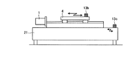
図10は、本発明に係る軌跡測定装置が適用される数値制御工作機械の実施の形態3の架台の加速度を測定する加速度計13の設置例を示す側面図である。図10において、可動軸を支える架台21にはワークテーブル4の運動に伴う反力が作用して振動が発生する。そのような場合、加速度計13bにより測定される加速度は絶対加速度であるため、その情報には架台21の振動加速度が含まれ、可動軸の変位を正しく解析することができなくなる。
FIG. 10 is a side view showing an installation example of the accelerometer 13 for measuring the acceleration of the gantry of the third embodiment of the numerically controlled machine tool to which the trajectory measuring apparatus according to the present invention is applied. In FIG. 10, a reaction force accompanying the movement of the work table 4 acts on the
そこで、機械の可動軸を支える架台21の加速度を測定するための加速度計13cを備え、加速度計13cの感度方向は可動軸の運動方向と略一致するように設置するとともに、図3の運動軌跡解析部14は、可動軸の加速度と架台21の加速度の相対加速度を算出し、その相対加速度を2回積分することで架台21と可動軸間の相対変位を求めるようにしてもよい。これにより、架台21の振動が無視できないほど大きい場合にも、機械運動軌跡を正確に測定できる。
Therefore, an
実施の形態4.
図11は、本発明に係る軌跡測定装置が適用される数値制御工作機械の実施の形態4のワークテーブル側と主軸側に加速度計を設置した例を示す斜視図である。図11において、工作機械のように3次元的な相対運動が問題となる場合には、相対運動を行う2つの機械要素にそれぞれ直交する3方向の加速度を測定するための加速度計22a、22bを備え、2つの機械要素に設置した加速度計22a,22bの感度方向が略一致するように設置するとともに、図3の運動軌跡解析部14は、2つの機械要素における各方向の加速度から相対加速度を算出し、相対加速度を2回積分して2つの機械要素間の相対変位を求めることにより、2つの機械要素間の3次元的な相対変位をより正確に測定できるようになる。
FIG. 11 is a perspective view showing an example in which accelerometers are installed on the work table side and the spindle side of the numerical control machine tool to which the trajectory measuring apparatus according to the present invention is applied. In FIG. 11, when three-dimensional relative motion becomes a problem as in a machine tool,
なお、図11の例では、主軸側とワークテーブル4側にそれぞれ3軸方向の加速度を測定可能な3軸加速度計22a,22bを設置した例を表しているが、通常の1軸加速度計を3個ずつ設置してもよいし、測定したい方向にのみ1軸加速度計を設置してもよい。
In the example of FIG. 11, an example in which
実施の形態5.
図3において、機械に加速度計13a、13bを設置する場合、加速度計13a、13bの感度が事前に正しく校正されているとは限らないし、加速度計13a、13bの正負方向が測定対象とする可動軸の正負方向に一致しているとは限らない。さらに、複数の加速度信号を伝達するための複数のケーブルが、その入力チャンネルに正しい順番で接続されているとも限らない。
Embodiment 5 FIG.
In FIG. 3, when the
そこで、可動軸の加速度と同一可動軸の検出位置を2回微分して求めた検出加速度、または加速度を1回積分して求めた機械速度と検出位置を1回微分して求めた検出速度、ないしは加速度を2回積分して求めた機械位置と検出位置とを比較し、加速度と検出加速度の波形における振幅、または機械速度と検出速度の波形における振幅、ないしは機械位置と検出位置の波形における振幅が一致するように、可動軸の加速度の振幅、または機械速度の振幅、ないしは機械位置の振幅を補正するようにしてもよい。これにより、加速度計13a、13bの感度を事前に校正する必要がなくなる。
Therefore, the detected acceleration obtained by differentiating the detected position of the same movable axis with the acceleration of the movable axis twice, or the machine speed obtained by integrating the acceleration once and the detected speed obtained by differentiating the detected position once, Or the machine position obtained by integrating acceleration twice and the detected position are compared, and the amplitude in the waveform of acceleration and detected acceleration, the amplitude in waveform of machine speed and detected speed, or the amplitude in waveform of machine position and detected position The amplitude of the acceleration of the movable axis, the amplitude of the machine speed, or the amplitude of the machine position may be corrected so that the two coincide. This eliminates the need to calibrate the sensitivity of the
また、可動軸の加速度と同一可動軸の検出位置を2回微分して求めた検出加速度、または加速度を1回積分して求めた機械速度と検出位置を1回微分して求めた検出速度、ないしは加速度を2回積分して求めた機械位置と検出位置との誤差を求め、誤差の振幅が、指令位置または検出位置から算出される加速度の振幅、または前令位置または検出位置から算出される速度の振幅、ないしは指令位置または検出位置の振幅より大きい場合に、可動軸の加速度、機械速度、または機械位置の符号を反転するようにしてもよい。これにより、加速度計の符号を事前に校正する必要がなくなる。 Further, the detected acceleration obtained by differentiating the detected position of the same movable axis with the acceleration of the movable axis twice, or the machine speed obtained by integrating the acceleration once and the detected speed obtained by differentiating the detected position once, Or, the error between the machine position obtained by integrating acceleration twice and the detected position is obtained, and the amplitude of the error is calculated from the acceleration amplitude calculated from the command position or the detected position, or from the previous position or the detected position. If the velocity amplitude is larger than the amplitude of the command position or the detection position, the acceleration of the movable axis, the machine speed, or the sign of the machine position may be reversed. This eliminates the need to calibrate the accelerometer sign in advance.
さらに、複数の可動軸の加速度と複数の可動軸の検出位置を2回微分して求めた検出加速度、または加速度を1回積分して求めた機械速度と検出位置を1回微分して求めた検出速度、ないしは加速度を2回積分して求めた機械位置と前記検出位置とを比較し、N(Nは正の整数)番目の可動軸の加速度と検出加速度、またはN番目の可動軸の機械速度と検出速度、ないしはN番目の可動軸の機械位置と検出位置の変動波形との間に、位相差が存在する場合には、N番目の機械速度データとN+1番目の機械速度データとを入れ替えるようにしてもよい。これにより、加速度信号の入力チャンネルを間違えた場合にも、機械運動軌跡を正しく測定できる。 Furthermore, the acceleration obtained by differentiating the acceleration of the plurality of movable axes and the detection positions of the plurality of movable axes twice, or the machine speed obtained by integrating the acceleration once and the detection position obtained by differentiating once. The machine position obtained by integrating twice the detected speed or acceleration is compared with the detected position, and the acceleration and detected acceleration of the Nth movable axis (N is a positive integer) or the machine of the Nth movable axis. If there is a phase difference between the speed and the detected speed, or the machine position of the Nth movable shaft and the fluctuation waveform of the detected position, the Nth machine speed data and the N + 1th machine speed data are switched. You may do it. As a result, even when the input channel of the acceleration signal is wrong, the mechanical motion trajectory can be measured correctly.
図12は、本発明に係る軌跡測定装置の実施の形態5の軌跡測定方法の概略の一例を示すフローチャートである。図12において、加速度aを1回積分して求めた速度と検出位置Pdを微分して求めた速度から、加速度計13a、13bの感度、入力チャンネル、および符号を校正する(ステップS1〜S3)。さらに、それらを校正した後の速度波形を積分して機械位置Pkを求め(ステップS4)、その機械位置Pkと検出位置Pdとを比較することで、積分誤差と加速度計13a、13bの設置誤差による影響を補正し(ステップS5)、例えば弾性変形量を推定した結果を加えて機械運動軌跡を表示する(ステップS6、S7)。
FIG. 12 is a flowchart showing an example of an outline of the trajectory measuring method according to the fifth embodiment of the trajectory measuring apparatus according to the present invention. In FIG. 12, the sensitivity, input channel, and sign of the
図13は、本発明に係る軌跡測定装置の実施の形態5の軌跡測定方法の詳細の一例を示すフローチャートである。なお、図13の例では、円運動を測定する場合を例に挙げた。また、解析は可動軸ごとに行うが、図13の例では、便宜上1軸分のみの処理を示した。 FIG. 13 is a flowchart showing an example of the details of the trajectory measuring method according to the fifth embodiment of the trajectory measuring apparatus according to the present invention. In the example of FIG. 13, the case of measuring circular motion is taken as an example. The analysis is performed for each movable axis, but in the example of FIG. 13, only the processing for one axis is shown for convenience.
図13において、この軌跡測定方法では、感度校正処理30、符号校正処理31、入力チャンネル補正処理32、誤差補正処理33および弾性変形推定処理34が行われる。感度校正処理30では、フィードバック位置を1回微分して求めた速度Vfb[m/s]の振幅Avfb[m/s](ステップS11、S12)と、加速度を1回積分して求めた速度Va[m/s]の振幅Ava[m/s](ステップS13、S14)との比Rを算出する(ステップS15)。速度振幅Avaは、速度Vaの最大値と最小値の差として求めることができる。ただし、極端に速度Vaが小さい、または分解能が低い場合には速度振幅Avaが正しく計算できなくなるが、このような低速運動では、そもそも加速度計13a、13bによる軌跡測定ができないので、加速度計13a、13bによる方法で運動軌跡が測定できる条件であれば、速度振幅Avaも問題なく求められる。
In FIG. 13, in this locus measurement method,
また、円運動中の速度振幅Avaは円運動の指令速度(F値)に相当し、微視的な振動による影響を除けばモータ端と機械端に違いはない。よって、速度振幅比Rは加速度の感度誤差とみなすことができ、加速度を1回積分して求めた速度Vaに速度振幅比Rを掛けることで、加速度計13a、13bの測定感度を校正できる(ステップS16)。なお、加速度計13a、13bの感度は速度振幅Avaから校正されるので、たとえ加速度の入力チャンネルや符号が反対になっていても結果には影響しない。
Further, the velocity amplitude Ava during the circular motion corresponds to the command speed (F value) of the circular motion, and there is no difference between the motor end and the machine end except for the influence of microscopic vibration. Therefore, the velocity amplitude ratio R can be regarded as an acceleration sensitivity error, and the measurement sensitivity of the
図14は、本発明に係る軌跡測定装置の実施の形態5の加速度信号の入力チャンネルの判別方法を説明する図である。なお、図14では、送り速度を3000mm/min、半径を10mmとした場合のX軸の速度波形を示した、また、図14(a)が正しいチャンネルに接続した場合、図14(b)はチャンネルが逆になっている場合の結果である。図14において、円運動では2つの軸がそれぞれ正弦波運動と余弦波運動を行っており、その位相は90°である。図14(a)に示すように、加速度信号が正しいチャンネルに入力されている場合には、加速度を積分して求めた速度Va’とフィードバック位置を微分して求めた速度Vfbとの位相は一致する。しかし、図14(b)に示すように、加速度の入力チャンネルが逆になっている場合には、速度Va’、Vfbの位相は位相差Pだけずれる。 FIG. 14 is a diagram for explaining a method of discriminating an input channel for acceleration signals according to the fifth embodiment of the trajectory measuring apparatus according to the present invention. 14 shows the X-axis velocity waveform when the feed rate is 3000 mm / min and the radius is 10 mm. Also, when FIG. 14A is connected to the correct channel, FIG. This is the result when the channels are reversed. In FIG. 14, in the circular motion, the two axes perform a sine wave motion and a cosine wave motion, respectively, and their phases are 90 °. As shown in FIG. 14A, when the acceleration signal is input to the correct channel, the phase of the velocity Va ′ obtained by integrating the acceleration and the velocity Vfb obtained by differentiating the feedback position are the same. To do. However, as shown in FIG. 14B, when the acceleration input channels are reversed, the phases of the velocities Va ′ and Vfb are shifted by the phase difference P.
そこで、符号校正処理31では、速度Vfbの半周期Tと速度Va’、Vfbの位相差Pを求め(ステップS17)、この位相差Pがある場合には、加速度計13a、13bが逆のチャンネルに接続されていると判断し、1軸目と2軸目のデータを交換する(ステップS18)。なお、この位相差Pは、加速度から求めた速度Va’の符号が反転する時刻Taとフィードバック位置から求めた速度Vfbの符号が反転する時刻Tfbとの差として算出している。
Therefore, in the
図15は、本発明に係る軌跡測定装置の実施の形態5の加速度信号の符号の判別方法を説明する図である。なお、図15の例では、送り速度3000mm/min、半径10mmの円運動を行った場合におけるフィードバック位置および加速度から求めた速度と、その2つの差を示した。また、図15(a)は2つのデータの符号が一致している場合の結果、図15(b)は加速度の符号がフィードバックに対して反転している場合の結果を示す。 FIG. 15 is a diagram for explaining a method of discriminating the sign of the acceleration signal in the fifth embodiment of the trajectory measuring apparatus according to the present invention. In the example of FIG. 15, the speed obtained from the feedback position and the acceleration when a circular motion with a feed speed of 3000 mm / min and a radius of 10 mm is performed, and the difference between the two are shown. FIG. 15A shows the result when the signs of the two data match, and FIG. 15B shows the result when the sign of the acceleration is reversed with respect to the feedback.
図15(a)において、2つのデータの符号が一致している場合には、2つの速度Va’、Vfbの速度差は円運動の送り速度の振幅Avfbである3000mm/minより小さいことがわかる。一方、図15(b)に示すように、加速度の符号がフィードバックに対して反転している場合には、2つの速度Va’、Vfbの差の最大値Difは送り速度の振幅Avfbよりも大きくなることがわかる。 In FIG. 15A, when the signs of the two data match, the speed difference between the two speeds Va ′ and Vfb is smaller than 3000 mm / min, which is the amplitude Avfb of the feed speed of the circular motion. . On the other hand, as shown in FIG. 15B, when the sign of acceleration is reversed with respect to feedback, the maximum value Dif of the difference between the two velocities Va ′ and Vfb is larger than the amplitude Avfb of the feed speed. I understand that
このため、入力チャンネル補正処理32では、2つの速度Va’、Vfbの差の最大値Difを求め(ステップS19)、2つの速度Va’、Vfbの差の最大値Difが送り速度の振幅Avfbよりも大きい場合には、加速度を積分して求めた速度Vaの符号を反転することで、加速度の符号を校正する(ステップS20)。
Therefore, in the input
次に、以上の処理で校正した後の速度を積分して機械位置Paを求め(ステップS21)、その校正後の機械位置Paと、フィードバックされた検出位置Pd(FBデータ)との差を算出する(ステップS22)。そして、校正後の機械位置Paとフィードバックされた検出位置Pd(FBデータ)との差を(3)式にて多項式近似する(ステップS23)。そして、この多項式により得られる解を、校正後の機械位置Paから差し引き(ステップS24)、弾性変形量を推定した結果を加えて機械運動軌跡を表示する(ステップS25、S26)。 Next, the machine position Pa is obtained by integrating the speed after the calibration in the above process (step S21), and the difference between the machine position Pa after the calibration and the detected position Pd (FB data) fed back is calculated. (Step S22). Then, the difference between the calibrated machine position Pa and the fed back detected position Pd (FB data) is approximated by a polynomial expression (3) (step S23). Then, the solution obtained by this polynomial is subtracted from the calibrated machine position Pa (step S24), and the result of estimating the amount of elastic deformation is added to display the machine motion trajectory (steps S25 and S26).
なお、図12から図15に示した実施例では、加速度を1回積分して求めた速度と、検出位置を1回微分して求めた速度とから、加速度計の感度、符号および入力チャンネルを校正している。しかし、速度の代わりに加速度や位置を使ったとしても、同じ方法で感度、符号および入力チャンネルを校正することができる。 In the embodiment shown in FIGS. 12 to 15, the sensitivity, sign, and input channel of the accelerometer are determined from the speed obtained by integrating the acceleration once and the speed obtained by differentiating the detected position once. I am calibrating. However, the sensitivity, sign and input channel can be calibrated in the same way even if acceleration or position is used instead of velocity.
以上の方法により、加速度計の感度、入力チャンネルおよび符号を自動的に認識して校正できる。円運動軌跡を一度測定し、そのときの校正結果を記憶させておけば、自由形状を測定するときにもその校正結果を利用できる。すなわち、円運動軌跡の測定により加速度計の校正も同時に可能となる。 By the above method, the sensitivity, input channel and sign of the accelerometer can be automatically recognized and calibrated. If the circular motion trajectory is measured once and the calibration result at that time is stored, the calibration result can be used when measuring the freeform. That is, the accelerometer can be calibrated simultaneously by measuring the circular motion trajectory.
以上のように本発明に係る軌跡測定装置は、加速度を2回積分して得られる機械位置と、検出位置または指令位置から推定される機械位置とを比較することで、加速度の測定とその積分に起因する誤差を分離し、機械位置を補正することができ、実際の使用状態にある機械の運動軌跡をジグや工具を外すことなく精度よく測定する方法に適している。 As described above, the trajectory measuring apparatus according to the present invention compares the machine position obtained by integrating acceleration twice with the machine position estimated from the detected position or the command position, thereby measuring the acceleration and integrating it. It is suitable for a method for accurately measuring the motion trajectory of a machine in an actual use state without removing a jig or a tool.
1x、1y、1z モータ
2x、2y、2z 送りねじ
3x、3y、3z 回転角度検出器
4 ワークテーブル
5 コラム
6 ラム
7 主軸頭
8y カップリング
9y ナット
10y サポートベアリング
11 指令生成部
12 モータ駆動部
13a〜13c 加速度計
14 運動軌跡解析部
14a 加速度積分部
14b 誤差補正部
15 運動軌跡表示部
16 工具
17 工作物
18 X軸加速度計
19 Y軸加速度計
21 架台
22a、22b 3軸加速度計
23 誤差波形近似部
K1、K2 減算器
30 感度校正処理
31 符号校正処理
32 入力チャンネル補正処理
33 誤差補正処理
34 弾性変形推定処理
1x, 1y, 1z
Claims (11)
前記機械の加速度を測定する加速度計と、
前記指令位置または前記検出位置ないしはその両方と前記加速度に基づいて前記機械の運動軌跡を解析する運動軌跡解析部とを備え、
前記運動軌跡解析部は、
前記加速度の積分結果に基づいて機械位置を算出する加速度積分部と、
前記指令位置または前記検出位置ないしはその両方に基づいて、前記機械位置を補正する誤差補正部とを備え、
さらに前記誤差補正部は、前記機械位置と、前記検出位置ないしは前記指令位置から推定される位置とを比較することで、前記加速度の測定誤差と積分誤差を分離して前記機械位置を補正することを特徴とする軌跡測定装置。 A trajectory measuring device that measures a motion trajectory of a machine whose machine position is controlled so that a detection position of a motor that drives a movable shaft follows a command position,
An accelerometer for measuring the acceleration of the machine;
E Bei and said command position or the detection position or motion trajectory analysis unit for analyzing the movement trajectory of the machine based on the acceleration and both,
The motion trajectory analysis unit
An acceleration integrator that calculates a machine position based on the integration result of the acceleration;
An error correction unit that corrects the machine position based on the command position or the detection position or both,
Further, the error correction unit corrects the machine position by separating the acceleration measurement error and the integration error by comparing the machine position with a position estimated from the detection position or the command position. Trajectory measuring device characterized by
前記機械の加速度を測定する加速度計と、 An accelerometer for measuring the acceleration of the machine;
前記指令位置または前記検出位置ないしはその両方と前記加速度に基づいて前記機械の運動軌跡を解析する運動軌跡解析部とを備え、 A motion trajectory analysis unit that analyzes the motion trajectory of the machine based on the command position or the detection position or both and the acceleration;
前記運動軌跡解析部は、前記加速度計の感度方向が、測定対象とする可動軸の方向に対して偏向していることで、測定対象とした可動軸以外の可動軸の運動による測定誤差が発生する場合において、前記測定誤差を解析的または数値的に求め、求めた誤差分だけ前記加速度または前記機械位置を補正することを特徴とする軌跡測定装置。 The motion trajectory analyzer generates a measurement error due to the movement of a movable axis other than the movable axis to be measured because the sensitivity direction of the accelerometer is deflected with respect to the direction of the movable axis to be measured. In this case, the trajectory measuring apparatus is characterized in that the measurement error is obtained analytically or numerically, and the acceleration or the machine position is corrected by the obtained error.
前記機械の加速度を測定する加速度計と、 An accelerometer for measuring the acceleration of the machine;
前記指令位置または前記検出位置ないしはその両方と前記加速度に基づいて前記機械の運動軌跡を解析する運動軌跡解析部とを備え、 A motion trajectory analysis unit that analyzes the motion trajectory of the machine based on the command position or the detection position or both and the acceleration;
前記運動軌跡解析部は、加速度を2回積分して機械位置を求め、数値積分による積分誤差が生じる場合において、前記積分誤差を指令位置から解析的または数値的に求め、求めた誤差分だけ前記機械位置を補正することを特徴とする軌跡測定装置。 The motion trajectory analysis unit integrates acceleration twice to determine a machine position, and when an integration error due to numerical integration occurs, the integration error is analytically or numerically determined from a command position, and the error is calculated by the calculated error. A trajectory measuring apparatus that corrects a machine position.
前記機械の加速度を測定する加速度計と、 An accelerometer for measuring the acceleration of the machine;
前記指令位置または前記検出位置ないしはその両方と前記加速度に基づいて前記機械の運動軌跡を解析する運動軌跡解析部とを備え、 A motion trajectory analysis unit that analyzes the motion trajectory of the machine based on the command position or the detection position or both and the acceleration;
前記加速度計の設置誤差および積分誤差の両方が存在した場合に生じる誤差波形を複数のパラメータを持つ数式として前記指令位置から求めるとともに、加速度を2回積分して求めた前記機械位置と前記検出位置または前記指令位置から推定される機械位置との差を前記数式で近似することで、前記加速度計の設置誤差および積分誤差を同定し、同定された誤差分だけ前記機械位置を補正することを特徴とする軌跡測定装置。 The machine position and the detection position obtained by calculating the error waveform generated when both the installation error and the integration error of the accelerometer exist from the command position as a mathematical expression having a plurality of parameters and integrating the acceleration twice. Alternatively, by approximating the difference from the machine position estimated from the command position with the mathematical formula, the accelerometer installation error and integration error are identified, and the machine position is corrected by the identified error. Trajectory measuring device.
前記第2の加速度計は、その感度方向が前記可動軸の運動方向と略一致するように設置され、
前記運動軌跡解析部は、前記可動軸の加速度と前記架台の加速度との相対加速度を算出し、前記相対加速度を前記機械の加速度として前記機械の運動軌跡を解析することを特徴とする請求項1から6のいずれか1項に記載の軌跡測定装置。 A second accelerometer that measures the acceleration of the cradle that supports the movable axis of the machine;
The second accelerometer is installed such that its sensitivity direction substantially coincides with the movement direction of the movable shaft,
2. The motion trajectory analysis unit calculates a relative acceleration between the acceleration of the movable shaft and the acceleration of the gantry, and analyzes the motion trajectory of the machine using the relative acceleration as the acceleration of the machine. The trajectory measuring apparatus according to any one of 1 to 6 .
前記運動軌跡解析部は、前記2つの機械要素における各方向の加速度から相対加速度を算出し、前記相対加速度を前記機械の加速度として前記機械の運動軌跡を解析することを特徴とする請求項1から6のいずれか1項に記載の軌跡測定装置。 The accelerometer measures accelerations in three orthogonal directions, and is installed so that the sensitivity directions of the accelerometers substantially coincide with each of two mechanical elements that perform relative motion,
2. The motion trajectory analysis unit calculates a relative acceleration from acceleration in each direction in the two machine elements, and analyzes the motion trajectory of the machine using the relative acceleration as the acceleration of the machine. The trajectory measuring apparatus according to any one of 6 .
Priority Applications (1)
| Application Number | Priority Date | Filing Date | Title |
|---|---|---|---|
| JP2009274745A JP5388823B2 (en) | 2009-12-02 | 2009-12-02 | Trajectory measuring device |
Applications Claiming Priority (1)
| Application Number | Priority Date | Filing Date | Title |
|---|---|---|---|
| JP2009274745A JP5388823B2 (en) | 2009-12-02 | 2009-12-02 | Trajectory measuring device |
Publications (2)
| Publication Number | Publication Date |
|---|---|
| JP2011115885A JP2011115885A (en) | 2011-06-16 |
| JP5388823B2 true JP5388823B2 (en) | 2014-01-15 |
Family
ID=44281835
Family Applications (1)
| Application Number | Title | Priority Date | Filing Date |
|---|---|---|---|
| JP2009274745A Active JP5388823B2 (en) | 2009-12-02 | 2009-12-02 | Trajectory measuring device |
Country Status (1)
| Country | Link |
|---|---|
| JP (1) | JP5388823B2 (en) |
Cited By (2)
| Publication number | Priority date | Publication date | Assignee | Title |
|---|---|---|---|---|
| EP4270769A4 (en) * | 2020-12-23 | 2024-06-05 | Panasonic Intellectual Property Management Co., Ltd. | Characteristic calculation device, characteristic calculation method, and program |
| EP4270777A4 (en) * | 2020-12-23 | 2024-06-05 | Panasonic Intellectual Property Management Co., Ltd. | Abnormality determining device, motor control device, abnormality determining method, and program |
Families Citing this family (7)
| Publication number | Priority date | Publication date | Assignee | Title |
|---|---|---|---|---|
| JP5738490B1 (en) * | 2013-12-05 | 2015-06-24 | 三菱電機株式会社 | Trajectory measuring device, numerical control device, and trajectory measuring method |
| JP6298672B2 (en) * | 2014-03-20 | 2018-03-20 | Dmg森精機株式会社 | Motion error measuring device and machine tool equipped with the same |
| EP3176657A1 (en) * | 2015-12-02 | 2017-06-07 | Siemens Aktiengesellschaft | Determining the stiffness of a drive train of a machine, in particular a machine tool or a production machine |
| DE112016006602T5 (en) * | 2016-03-16 | 2018-12-13 | Mitsubishi Electric Corporation | Machine motion trajectory measuring device |
| EP3569367B1 (en) | 2018-05-17 | 2022-08-03 | Siemens Aktiengesellschaft | Computer-aided determination of a movement of a device |
| JP7257870B2 (en) * | 2019-05-08 | 2023-04-14 | オークマ株式会社 | Maximum load estimation device and machine damage diagnosis device at the time of collision |
| CN113447801B (en) * | 2020-03-25 | 2024-03-15 | 法雷奥汽车内部控制(深圳)有限公司 | Switch position detection device and method for sliding switch |
Family Cites Families (5)
| Publication number | Priority date | Publication date | Assignee | Title |
|---|---|---|---|---|
| US5834623A (en) * | 1995-03-03 | 1998-11-10 | Ignagni; Mario B. | Apparatus and method to provide high accuracy calibration of machine tools |
| JP2005081444A (en) * | 2003-09-04 | 2005-03-31 | Toshiba Mach Co Ltd | Device and method for measuring accuracy of driving device, program for measuring accuracy of driving device, recording medium recording the program, and method for calibrating driving device |
| EP1803536A1 (en) * | 2004-08-25 | 2007-07-04 | Kabushiki Kaisha Yaskawa Denki | Robot evaluation system and evaluation method |
| JP4283214B2 (en) * | 2004-12-16 | 2009-06-24 | ファナック株式会社 | Machine tip control device |
| JP2009254697A (en) * | 2008-04-18 | 2009-11-05 | Panasonic Electric Works Co Ltd | Exercise system |
-
2009
- 2009-12-02 JP JP2009274745A patent/JP5388823B2/en active Active
Cited By (2)
| Publication number | Priority date | Publication date | Assignee | Title |
|---|---|---|---|---|
| EP4270769A4 (en) * | 2020-12-23 | 2024-06-05 | Panasonic Intellectual Property Management Co., Ltd. | Characteristic calculation device, characteristic calculation method, and program |
| EP4270777A4 (en) * | 2020-12-23 | 2024-06-05 | Panasonic Intellectual Property Management Co., Ltd. | Abnormality determining device, motor control device, abnormality determining method, and program |
Also Published As
| Publication number | Publication date |
|---|---|
| JP2011115885A (en) | 2011-06-16 |
Similar Documents
| Publication | Publication Date | Title |
|---|---|---|
| JP5388823B2 (en) | Trajectory measuring device | |
| US9144869B2 (en) | Machine motion trajectory measuring device, numerically controlled machine tool, and machine motion trajectory measuring method | |
| US10543574B2 (en) | Machine motion trajectory measuring apparatus | |
| JP4829359B2 (en) | Calculation method of probe mounting position of on-machine measuring device | |
| JP4819665B2 (en) | Non-circular shape processing equipment | |
| US20140025195A1 (en) | Computer Numerical Control Devices Employing Accelerometers And Associated Feedback Method | |
| JP5404507B2 (en) | Correction parameter adjustment device | |
| JP5249452B1 (en) | Trajectory display device considering correction data | |
| JP2017503157A (en) | Calibrate the position of the motion system by using inertial sensors | |
| US9921568B2 (en) | Trajectory measuring device, numerical control device, and trajectory measuring method | |
| US9110458B2 (en) | Positioning control apparatus and machine tool provided therewith | |
| CN112207629A (en) | Compensation method for open-loop dynamic error of motion control mechanism | |
| JP5091702B2 (en) | Probe straightness measurement method | |
| JP4618616B2 (en) | Numerical controller | |
| KR20230029941A (en) | Manufacturing method of processing machine, processing system and work piece | |
| EP3864474B1 (en) | Measurement system, and a method in relation to the measurement system | |
| US11409258B2 (en) | Information processing device and information processing method | |
| JP4503148B2 (en) | Compensator for feeding mechanism of numerically controlled machine tool and numerically controlled machine tool | |
| JP2003157114A (en) | Method and device for lost motion correction | |
| JP5300831B2 (en) | Mechanical angle measuring device | |
| JP2017068391A (en) | Numerical control device and method for compensating for lost motion of numerical control device | |
| JP5225060B2 (en) | Mechanical motion measuring device | |
| JP2018128350A (en) | Position detector, stage device, and shape measuring device | |
| JP2015191271A (en) | trajectory error display device | |
| JP2012146006A (en) | Positioning control device |
Legal Events
| Date | Code | Title | Description |
|---|---|---|---|
| A621 | Written request for application examination |
Free format text: JAPANESE INTERMEDIATE CODE: A621 Effective date: 20111018 |
|
| A977 | Report on retrieval |
Free format text: JAPANESE INTERMEDIATE CODE: A971007 Effective date: 20130329 |
|
| A131 | Notification of reasons for refusal |
Free format text: JAPANESE INTERMEDIATE CODE: A131 Effective date: 20130702 |
|
| A521 | Request for written amendment filed |
Free format text: JAPANESE INTERMEDIATE CODE: A523 Effective date: 20130822 |
|
| TRDD | Decision of grant or rejection written | ||
| A01 | Written decision to grant a patent or to grant a registration (utility model) |
Free format text: JAPANESE INTERMEDIATE CODE: A01 Effective date: 20130910 |
|
| A61 | First payment of annual fees (during grant procedure) |
Free format text: JAPANESE INTERMEDIATE CODE: A61 Effective date: 20131008 |
|
| R150 | Certificate of patent or registration of utility model |
Ref document number: 5388823 Country of ref document: JP Free format text: JAPANESE INTERMEDIATE CODE: R150 Free format text: JAPANESE INTERMEDIATE CODE: R150 |
|
| R250 | Receipt of annual fees |
Free format text: JAPANESE INTERMEDIATE CODE: R250 |
|
| R250 | Receipt of annual fees |
Free format text: JAPANESE INTERMEDIATE CODE: R250 |
|
| R250 | Receipt of annual fees |
Free format text: JAPANESE INTERMEDIATE CODE: R250 |
|
| R250 | Receipt of annual fees |
Free format text: JAPANESE INTERMEDIATE CODE: R250 |
|
| R250 | Receipt of annual fees |
Free format text: JAPANESE INTERMEDIATE CODE: R250 |
|
| R250 | Receipt of annual fees |
Free format text: JAPANESE INTERMEDIATE CODE: R250 |
|
| R250 | Receipt of annual fees |
Free format text: JAPANESE INTERMEDIATE CODE: R250 |
|
| R250 | Receipt of annual fees |
Free format text: JAPANESE INTERMEDIATE CODE: R250 |