JP5386925B2 - Cylindrical linear motor - Google Patents
Cylindrical linear motor Download PDFInfo
- Publication number
- JP5386925B2 JP5386925B2 JP2008268638A JP2008268638A JP5386925B2 JP 5386925 B2 JP5386925 B2 JP 5386925B2 JP 2008268638 A JP2008268638 A JP 2008268638A JP 2008268638 A JP2008268638 A JP 2008268638A JP 5386925 B2 JP5386925 B2 JP 5386925B2
- Authority
- JP
- Japan
- Prior art keywords
- teeth
- mover
- linear motor
- cylindrical linear
- small
- Prior art date
- Legal status (The legal status is an assumption and is not a legal conclusion. Google has not performed a legal analysis and makes no representation as to the accuracy of the status listed.)
- Expired - Fee Related
Links
Images


Description
本発明は、半導体製造装置などの精密位置決め装置の直動機構に使用されているリニアモータの中で特に重力方向の小ストローク位置決め用途に向けたものであり、小型でありながら高推力、推力リプル低減が求められる円筒形リニアモータに関する。 The present invention is particularly intended for small stroke positioning applications in the gravitational direction among linear motors used in linear motion mechanisms of precision positioning devices such as semiconductor manufacturing equipment. It is small in size but has high thrust and thrust ripple. The present invention relates to a cylindrical linear motor that is required to be reduced.
従来、半導体製造装置などの精密位置決め装置の直動機構に使用されると共に、固定子と可動子が円筒形を成し、固定子が電機子巻線を巻装した複数のティースとそのティース先端に軸方向等間隔に設けられた小歯から構成され、可動子が軸方向等間隔に配置された磁極から構成された、円筒形リニアモータが提案されている(例えば、特許文献1及び特許文献2参照)。
特許文献1の円筒形リニアモータは、ティースを有する固定子コアが電磁鋼板の積層により構成されており、1枚の電磁鋼板中に有する小歯の数が相数とティースの数により決められている。電磁鋼板が回転積層されることで、小歯が隣接するティース間で軸方向にずれるように配置される。小歯の軸方向ピッチが電磁鋼板の厚さ×ティース数に設定されているので、ステッピングモータとして駆動した場合、ステップごとの基本移動量を小さくできる。また、回転モータと同様の製造方法により電機子巻線をティースに巻装することができるので、スロット内の導体数を多くでき高推力にすることができる。
特許文献2の円筒形リニアモータは、特許文献1の可動子を改良したものである。可動子は薄板の永久磁石が2枚の薄板の可動子コアで挟まれ、その組合せが軸方向等間隔に並べて構成される。特許文献1に比べ、ギャップの磁束密度を高めることができ、さらに高推力にすることができる。
以下、特許文献1を例に従来の円筒形リニアモータを説明する。
図13は第1従来技術(特許文献1)による円筒形リニアモータの側断面図、図14は図13を軸方向から見た正断面図である。図において、1は可動子、2はシャフト、3は永久磁石、4は可動子コア、5は凸部、100は固定子、101はフレーム、102は電機子巻線、103は固定子コア、104はティース、105は小歯である。
可動子1はシャフト2、永久磁石3、可動子コア4から構成されている。シャフト2の外周に2個の可動子コア4と1個の永久磁石3が配置され、可動子コア4の外周表面に凸部5が形成されている。軸方向上側の可動子コア4の凸部5はN極の磁極となり、軸方向下側の可動子コア4の凸部5はS極の磁極となっている。このように構成された可動子1は、図示しない支持機構により固定子10と所定の磁気的空隙を介して相対移動できるようにされている。
固定子100はフレーム101、電機子巻線102、固定子コア103、ティース104、小歯105から構成されている。フレーム101の内周に固定子コア103が設けられ、固定子コア103の円周方向には6個のティース104が形成されている。そのティース104に3相の電機子巻線102が巻装されている。固定子コア103の材料には電磁鋼板の積層体が用いられている。3相の電機子巻線102はティース104と同数の6個のコイルにより構成されており、各コイルは図14において時計方向の順にU相、V相、W相、U相、V相、W相となっている。
また、ティース104の内周表面には軸方向等間隔に小歯105が形成されている。図15は図13に示す可動子1側から見た小歯105の配置展開図である。同図の上下方向と左右方向は、円筒形リニアモータのそれぞれ軸方向と円周方向を表している。つまり、上下方向に並ぶ小歯105は各ティース104上での並びを表し、左右方向はティース104の並びを表している。
特許文献1によると、kを1以上の整数、mを相数、nをm/2より小さくm/2に最も近い値の整数とするとき、電磁鋼板はk×m個のティースを有するとともに、1枚の電磁鋼板中の小歯105がn×k個とするように決められている。図13、14に示す円筒形リニアモータは、相数m=3、ティース104の数を6としているので、n=1、k=2であり、1枚の電磁鋼板中の小歯105はn×k=2個となっている。従って、図15に示すような小歯105の並びとなっており、小歯105の厚さtと軸方向ピッチλの関係は必然的に
t/λ=1/3
となる。
例えば、相数m=3、ティースの数を9とすると、n=1、k=3となるので、1枚の電磁鋼板中の小歯はn×k=3個となり、小歯の厚さtと軸方向ピッチλの関係はt/λ=1/3となる。従って、3相の場合はティースの数に限らず、t/λが1/3に決定される。
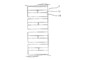
次に、図16は第2従来技術(特許文献2)による円筒形リニアモータの可動子の側面から見た断面拡大図である。図において、13は永久磁石、14は可動子コアである。特許文献1と異なり、薄板の永久磁石が2枚の薄板の可動子コアで挟まれ、その組合せが軸方向等間隔に並べて配置されている。永久磁石23の磁化方向はすべて同じ軸方向となっている。
このように構成された従来技術による円筒形リニアモータは、電機子巻線にサーボモータとして3相交流電流を供給したり、ステッピングモータとして矩形波状の電流を供給することで、可動子に軸方向の推力を発生させることができる。
In the cylindrical linear motor of
The cylindrical linear motor of
Hereinafter, a conventional cylindrical linear motor will be described using
13 is a side sectional view of a cylindrical linear motor according to the first prior art (Patent Document 1), and FIG. 14 is a front sectional view of FIG. 13 viewed from the axial direction. In the figure, 1 is a mover, 2 is a shaft, 3 is a permanent magnet, 4 is a mover core, 5 is a convex part, 100 is a stator, 101 is a frame, 102 is an armature winding, 103 is a stator core, 104 is a tooth and 105 is a small tooth.
The
The
According to
It becomes.
For example, if the number of phases is m = 3 and the number of teeth is 9, then n = 1 and k = 3, so there are n × k = 3 small teeth in one electromagnetic steel sheet, and the thickness of the small teeth The relationship between t and the axial pitch λ is t / λ = 1/3. Therefore, in the case of three phases, not only the number of teeth but t / λ is determined to be 1/3.
Next, FIG. 16 is an enlarged cross-sectional view seen from the side of the mover of the cylindrical linear motor according to the second prior art (Patent Document 2). In the figure, 13 is a permanent magnet, and 14 is a mover core. Unlike
The cylindrical linear motor according to the related art configured as described above is configured such that a three-phase alternating current is supplied to the armature winding as a servo motor or a rectangular wave current is supplied to the armature as a stepping motor. The thrust can be generated.
しかし、従来技術の円筒形リニアモータには次のような問題があった。
特許文献1の構成は、小歯の厚さtと軸方向ピッチλの関係がt/λ=1/3に設定されている。一般にt/λが小さいと推力/電流比は大きくできるものの、電流を大きくすると巻線磁束の増大にともない小歯が磁気飽和を起こしてしまう。つまり、推力が飽和し、所定の最大推力が得られなくなる問題があった。
また、t/λが小さいので、ギャップのパーミンアス分布は高調波成分を多く含む歪なものとなり、コギング力が大きくなった。コギング力が大きいと、ステッピングモータとして駆動した場合は静止位置誤差が大きくなり、サーボモータとして駆動した場合は送り時の振動が大きくなるなどの問題を引き起こした。さらに、特許文献2の構成は、永久磁石の磁化方向がすべて同じ軸方向になっている。そのため、永久磁石が作る磁束のうち固定子側を通る有効磁束はわずかで、可動子コア間を漏れ渡って軸方向に通る漏れ磁束が圧倒的に多くなっていた。その結果、所定の推力を得られない問題があった。
本発明はこのような問題点に鑑みてなされたものであり、円筒形リニアモータにおいて、推力を大きくでき、かつ、コギング力を小さくできる円筒形リニアモータを提供することを目的とする。
However, the conventional cylindrical linear motor has the following problems.
In the configuration of
Further, since t / λ is small, the permeation distribution of the gap is distorted including a lot of harmonic components, and the cogging force is increased. When the cogging force is large, the stationary position error increases when driven as a stepping motor, and the vibration during feeding increases when driven as a servo motor. Furthermore, in the configuration of
The present invention has been made in view of such problems, and an object of the present invention is to provide a cylindrical linear motor capable of increasing thrust and reducing cogging force in a cylindrical linear motor.
上記問題を解決するため、請求項1に記載の発明は、3相電機子巻線を巻装した複数のティースを円周方向に配置すると共に、前記ティースのギャップ面に軸方向等間隔に小歯を配置した固定子と、前記固定子と磁気的空隙を介して対向すると共に、軸方向等間隔に磁極を配置した可動子と、を備えた円筒形リニアモータにおいて、前記小歯の軸方向の厚さをt、軸方向ピッチをλとした場合、2/5<t/λ≦1/2とし、前記可動子の磁極の極ピッチをτ、前記磁極の極数である界磁極数をPmとした場合、λ/2−λ/(6×Pm)≦τ<λ/2 または λ/2<τ≦λ/2+λ/(6×Pm)としたことを特徴としている。
また、請求項2記載の発明は、請求項1記載の円筒形リニアモータにおいて、前記3相電機子巻線が作る磁界の極数である電機子極数をPa、前記ティース数をNとした場合、隣接する前記ティースとの間の前記小歯の軸方向ずれδを、δ=Pa・λ/(2×N)としたことを特徴としている。
また、請求項3記載の発明は、請求項1または2記載の円筒形リニアモータにおいて、前記可動子の磁極を可動子コアと永久磁石で構成すると共に、前記可動子コアと前記永久磁石を軸方向に交互に配置し、隣接する前記永久磁石の磁化方向を軸方向にして対極させたことを特徴としている。
また、請求項4記載の発明は、請求項1〜3までの何れか1項に記載の円筒形リニアモータにおいて、前記小歯の形状を階段状もしくは台形状にしたことを特徴としている。
In order to solve the above problem, the invention according to
According to a second aspect of the present invention, in the cylindrical linear motor according to the first aspect, the number of armature poles, which is the number of magnetic fields generated by the three-phase armature winding, is Pa, and the number of teeth is N. In this case, the axial displacement δ of the small teeth between adjacent teeth is δ = Pa · λ / (2 × N) .
According to a third aspect of the present invention, in the cylindrical linear motor according to the first or second aspect, the magnetic pole of the mover is constituted by a mover core and a permanent magnet, and the mover core and the permanent magnet are pivoted. The electrodes are alternately arranged in the direction, and are opposite to each other with the magnetization direction of the adjacent permanent magnets as the axial direction.
According to a fourth aspect of the present invention, in the cylindrical linear motor according to any one of the first to third aspects, the shape of the small teeth is stepped or trapezoidal.
請求項1に記載の発明によると、小歯の厚さtと軸方向ピッチλの関係t/λを従来技術よりも大きくしているので、固定子の小歯の磁気飽和を抑制し、最大推力を大きくすることができる。また、可動子の磁極ピッチを固定子の小歯ピッチ/2よりも少し小さくまたは大きく設定しているので、各磁極に発生するコギング力を可動子全体で相殺することができ、コギング力を大幅に低減することができる。
また、請求項2に記載の発明によると、隣接するティース間での小歯の軸方向ずれδをティース数と電機子極数に合わせ推力が最大となるように規定しているので、推力/電流比を大きくし、推力を有効的に発生させることができる。さらに、ギャップのパーミアンス分布の高調波成分も低減されるので、コギング力を低減することができる。
また、請求項3に記載の発明によると、可動子コアと永久磁石を軸方向に交互に配置し、隣接する永久磁石の磁化方向を軸方向にして対極するようにしている。そのため、可動子コアで集中された永久磁石の磁束が固定子側を通る有効磁束となるので、推力を大幅に向上することができる。
また、請求項4に記載の発明によると、小歯の形状を階段状もしくは台形状にしているので、請求項1に比べ、ギャップのパーミアンス分布をより滑らかにし、コギング力を更に低減することができる。
According to the first aspect of the present invention, since the relationship t / λ between the thickness t of the small teeth and the axial pitch λ is larger than that in the prior art, the magnetic saturation of the small teeth of the stator is suppressed, and the maximum Thrust can be increased. In addition, since the magnetic pole pitch of the mover is set slightly smaller or larger than the small tooth pitch / 2 of the stator, the cogging force generated in each magnetic pole can be offset by the entire mover, greatly increasing the cogging force. Can be reduced.
Further, according to the invention described in
According to the third aspect of the present invention, the mover cores and the permanent magnets are alternately arranged in the axial direction so that the magnetization directions of the adjacent permanent magnets are opposite to each other in the axial direction. Therefore, the magnetic flux of the permanent magnet concentrated by the mover core becomes an effective magnetic flux passing through the stator side, so that the thrust can be greatly improved.
Further, according to the invention described in claim 4, since the shape of the small teeth is stepped or trapezoidal, the gap permeance distribution can be made smoother and the cogging force can be further reduced as compared with
以下、本発明の実施の形態について図を参照して説明する。 Hereinafter, embodiments of the present invention will be described with reference to the drawings.
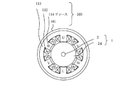
図1は本発明の第1実施例を示す円筒形リニアモータの側断面図、図2は図1に示す可動子の拡大側断面図、図3は図1を軸方向から見た正断面図である。以下、本発明が従来技術と同一の構成要素については同一の符号を付して説明する。
図において、23は永久磁石、24は可動子コア、112は電機子巻線、113は固定子コア、114はティース、115は小歯である。可動子1はシャフト2、永久磁石23、可動子コア24から構成されている。シャフト2の外周に可動子コア24と永久磁石23を軸方向に交互に配置するとともに、隣接する永久磁石23の磁化方向を軸方向に対極するようにして、それを磁極数(界磁極数)Pm=16個組み合わせている。このように構成した可動子1を、図示しない支持機構により固定子100と所定の磁気的空隙を介して相対移動できるようにしている。
固定子10はフレーム101、電機子巻線112、固定子コア113、ティース114、小歯115から構成されている。フレーム101の内周に固定子コア113を設け、固定子コア113の円周方向に6個のティース114を形成し、そのティース114に3相の電機子巻線112を巻装している。固定子コア113の材料には磁性体である電磁鋼板の積層体や焼結コアの成形体を用いることでき、第1実施例では電磁鋼板の積層体としている。3相の電機子巻線112をティース114と同数の6個のコイルにより構成しており、各コイルを図2において時計方向の順にU相、V相、W相、U相、V相、W相となるように配置している。このようなコイルの相順にすることで、3相の電機子巻線112が作る回転磁界の極数(電機子極数)はPa=4となっている。
また、ティース114の内周表面には軸方向等間隔に小歯115を形成している。図4は図1に示す可動子1側から見た小歯115の配置展開図である。第1実施例では小歯115の軸方向厚さtと軸方向ピッチλの関係を、
t/λ=1/2
としている。従来技術はt/λ=1/3であるので、第1実施例のt/λは1.5倍大きくなっている。さらに、小歯115を隣接するティース114間で軸方向にずらして配置させている。ティース114の数をNとした場合、隣接するティース114との間で生じる小歯115の軸方向ずれδを
δ=Pa・λ/(2×N)=λ/3
になるように設定している。
上記した式の関係から、1枚の電磁鋼板中に有する小歯115の数は図4を見てわかるように2個と4個が繰り返すようになっている。つまり、従来技術が2個の電磁鋼板だけであったのに対し、新たに4個の電磁鋼板が入っている。
FIG. 1 is a side sectional view of a cylindrical linear motor showing a first embodiment of the present invention, FIG. 2 is an enlarged side sectional view of a mover shown in FIG. 1, and FIG. 3 is a front sectional view of FIG. It is. In the following, the same components as those of the prior art will be described with the same reference numerals.
In the figure, 23 is a permanent magnet, 24 is a mover core, 112 is an armature winding, 113 is a stator core, 114 is a tooth, and 115 is a small tooth. The
The stator 10 includes a
Small teeth 115 are formed on the inner peripheral surface of the tooth 114 at equal intervals in the axial direction. FIG. 4 is an exploded view of the arrangement of the small teeth 115 as viewed from the side of the
t / λ = 1/2
It is said. Since t / λ = 1/3 in the prior art, t / λ of the first embodiment is 1.5 times larger. Further, the small teeth 115 are arranged so as to be shifted in the axial direction between the adjacent teeth 114. When the number of the teeth 114 is N, the axial displacement δ of the small teeth 115 occurring between the adjacent teeth 114 is δ = Pa · λ / (2 × N) = λ / 3
It is set to become.
From the relationship of the above formula, the number of small teeth 115 in one electromagnetic steel plate is two and four as shown in FIG. That is, while the prior art is only two electromagnetic steel sheets, four new electromagnetic steel sheets are included.
以上のような構成において、電機子巻線112に3相交流電流を供給すると、回転磁界を生じる。その回転磁界はティース14の先端の小歯115で変調され、軸方向の進行磁界になる。この進行磁界と可動子1の磁極との電磁作用によって、可動子1は軸方向に推力を発生する。
In the above configuration, when a three-phase alternating current is supplied to the armature winding 112, a rotating magnetic field is generated. The rotating magnetic field is modulated by the small teeth 115 at the tip of the
以上のように構成された円筒形リニアモータは、小歯の厚さtと軸方向ピッチλの関係であるt/λを従来技術に比べ大きく設定しているので、固定子の小歯の磁気飽和を抑制し、最大推力を大きくすることができる。また、永久磁石の磁束を可動子コアに集中させ、固定子に流れる有効磁束としているので、推力/電流比を大きく大きくすることができる。さらに、ギャップのパーミアンス分布の高調波成分も低減されるので、コギング力を低減することができる。 In the cylindrical linear motor configured as described above, t / λ, which is the relationship between the thickness t of the small teeth and the axial pitch λ, is set to be larger than that in the prior art. Saturation can be suppressed and the maximum thrust can be increased. Further, since the magnetic flux of the permanent magnet is concentrated on the mover core and used as the effective magnetic flux flowing through the stator, the thrust / current ratio can be greatly increased. Furthermore, since the harmonic component of the gap permeance distribution is also reduced, the cogging force can be reduced.
次に本発明の第2実施例について説明する。
図5は本発明の第2実施例を示す円筒形リニアモータの側断面図、図6は図5を軸方向から見た正断面図である。である。また、図7は図5に示す可動子側から見た小歯の配置展開図である。図において、122は電機子巻線、123は固定子コア、124はティース、125は小歯である。
第2実施例が第1実施例と異なる点は、ティース124の数をN=9、電機子極数をPa=8とし、小歯125の厚さtと軸方向ピッチλを
t/λ=4/9
としたことである。従来技術はt/λ=1/3であるので、第2実施例のt/λは1.33倍大きくなっている。
また、ティース124の数をN=9、電機子極数をPa=8としているので、図6における電機子巻線122の9個のコイルを時計方向の順にU相、U´相、V´相、V相、V´相、W´相、W相、W´相、U´相としている(U´相、V´相、W´相で示されるコイルはU相、V相、W相で示されるコイルと反対のコイル巻線方向(逆相)を示す)。
そして、隣接するティース124間の小歯125の軸方向ずれδを
δ=Pa・λ/(2×N)=4×λ/9
としている。
上記した式の関係から、ティースの数N=9における1枚の電磁鋼板中に有する小歯の数は図7を見てわかるように4個となっている。従来技術でティース数N=9とすると、1枚の電磁鋼板中に有する小歯の数は前記したように3個となる。従って、従来技術とは異なる構成となっている。
Next, a second embodiment of the present invention will be described.
FIG. 5 is a side sectional view of a cylindrical linear motor showing a second embodiment of the present invention, and FIG. 6 is a front sectional view of FIG. 5 viewed from the axial direction. It is. FIG. 7 is an exploded view of the arrangement of small teeth as viewed from the mover side shown in FIG. In the figure, 122 is an armature winding, 123 is a stator core, 124 is a tooth, and 125 is a small tooth.
The second embodiment differs from the first embodiment in that the number of teeth 124 is N = 9, the number of armature poles is Pa = 8, the thickness t of the
It is that. Since t / λ = 1/3 in the prior art, t / λ of the second embodiment is 1.33 times larger.
Further, since the number of teeth 124 is N = 9 and the number of armature poles is Pa = 8, the nine coils of the armature winding 122 in FIG. 6 are arranged in the clockwise order in the U phase, U ′ phase, V ′. Phase, V phase, V ′ phase, W ′ phase, W phase, W ′ phase, U ′ phase (the coils indicated by U ′ phase, V ′ phase, W ′ phase are U phase, V phase, W phase) The coil winding direction (reverse phase) opposite to the coil indicated by is shown).
Then, the axial deviation δ of the
It is said.
From the relationship of the above formula, the number of small teeth in one electromagnetic steel sheet with the number N of teeth is 9 as shown in FIG. Assuming that the number of teeth N = 9 in the prior art, the number of small teeth in one electromagnetic steel sheet is three as described above. Therefore, the configuration is different from that of the prior art.
以上のような構成において、電機子巻線122に3相交流電流を供給すると、第1実施例と同様の原理により、可動子1に推力を発生させることができる。
In the above configuration, when a three-phase alternating current is supplied to the armature winding 122, thrust can be generated in the
以上のように構成された円筒形リニアモータは、第1実施例とはティース数や電機子極数、1枚の電磁鋼板中の小歯数が異なっている。このように異なる構造においても、第1実施例と同様に、最大推力を大きくでき、コギング力を低減することができる。さらに、隣接するティース間での小歯の軸方向ずれδを、ティース数と電機子極数に合わせ推力が最大となるように規定している。つまり、同じティース数であっても従来技術とは異なる電機子巻線と小歯の配置になっており、より推力/電流比を大きくし推力を有効的に発生させるようになっている。 The cylindrical linear motor configured as described above differs from the first embodiment in the number of teeth, the number of armature poles, and the number of small teeth in one electromagnetic steel sheet. Even in such a different structure, the maximum thrust can be increased and the cogging force can be reduced as in the first embodiment. Further, the axial deviation δ of the small teeth between adjacent teeth is defined so as to maximize the thrust in accordance with the number of teeth and the number of armature poles. In other words, even with the same number of teeth, the arrangement of armature windings and small teeth is different from that of the prior art, and the thrust / current ratio is further increased to effectively generate thrust.
なお、第1実施例および第2実施例で説明した効果は、小歯の厚さtと軸方向ピッチλの関係を従来技術のt/λ=1/3よりも大きな2/5とすることで、より大きな効果を得ることができる。また、1/2よりも大きくすると、推力/電流比や最大推力がかえって低下してしまう。従って、本発明では
2/5 < t/λ ≦ 1/2
の条件を満たすこととしている。軸方向ピッチλあたりの電磁鋼板の枚数を3の倍数とし、この条件を満たすt/λを求めると、以下のとおりとなる。
電磁鋼板の枚数が 3枚の場合 適合するものなし
6枚の場合 t/λ=3/6=1/2 (第1実施例に適用)
9枚の場合 t/λ=4/9 (第2実施例に適用)
12枚の場合 t/λ=5/12
t/λ=6/12=1/2
15枚の場合 t/λ=7/15
18枚の場合 t/λ=8/18=4/9
t/λ=9/18=1/2
以上のように電磁鋼板の枚数を設定することで、第1実施例、第2実施例と同様の効果を得ることができる。なお、電磁鋼板の枚数を多くしλを大きくしすぎると、小歯の数が少なくなり、推力/電流比が低下してしまう。よって、18枚より多く設定することは、設計上ほとんどないと言える。
The effect described in the first and second embodiments is that the relationship between the small tooth thickness t and the axial pitch λ is 2/5, which is larger than t / λ = 1/3 of the prior art. Thus, a greater effect can be obtained. On the other hand, if the ratio is larger than 1/2, the thrust / current ratio and the maximum thrust are reduced. Therefore, in the present invention, 2/5 <t / λ ≦ 1/2
It is supposed to satisfy the conditions. When the number of electromagnetic steel sheets per axial pitch λ is a multiple of 3 and t / λ satisfying this condition is obtained, the following is obtained.
When the number of electrical steel sheets is 3 None
In the case of 6 sheets t / λ = 3/6 = 1/2 (applied to the first embodiment)
In case of 9 sheets t / λ = 4/9 (applied to the second embodiment)
In case of 12 sheets t / λ = 5/12
t / λ = 6/12 = 1/2
In case of 15 sheets t / λ = 7/15
In case of 18 sheets t / λ = 8/18 = 4/9
t / λ = 9/18 = 1/2
By setting the number of electromagnetic steel sheets as described above, the same effects as those of the first and second embodiments can be obtained. If the number of electromagnetic steel sheets is increased and λ is increased too much, the number of small teeth decreases and the thrust / current ratio decreases. Therefore, it can be said that setting more than 18 is hardly in design.
次に本発明の第3の実施例について説明する。
図8〜図11は本発明の第3の実施例を示す側面から見た小歯の形状である。図において、135、145、155、165すべて小歯である。
図8は第1実施例における小歯を階段状に形成し、新たに小歯135として構成したものである。小歯135は電磁鋼板3枚のうち外側2枚の内径を大きくすることで階段状としている。
図9は第2実施例における小歯を階段状に形成し、新たに小歯145として構成したものである。小歯145は電磁鋼板4枚のうち外側2枚の内径を大きくすることで階段状としている。
図10は小歯の厚さtと軸方向ピッチλの関係をt/λ=5/12として構成した場合について、その小歯を階段状に形成し、新たに小歯155として構成したものである。小歯155は電磁鋼板5枚のうち外側2枚の内径を最も大きくし、次に内側2枚の内径を少し大きくすることで階段状としている。
図11は固定子コアを焼結コアで構成した場合であり、小歯165を台形状に形成したものである。
Next, a third embodiment of the present invention will be described.
8 to 11 show the shape of the small teeth as seen from the side, showing the third embodiment of the present invention. In the figure, 135, 145, 155, and 165 are all small teeth.
FIG. 8 shows a configuration in which the small teeth in the first embodiment are formed stepwise and newly formed as small teeth 135. The small teeth 135 are stepped by increasing the inner diameter of the outer two of the three electromagnetic steel sheets.
FIG. 9 shows a configuration in which the small teeth in the second embodiment are formed in a step shape and newly formed as small teeth 145. The small teeth 145 are stepped by increasing the inner diameter of the outer two of the four electromagnetic steel sheets.
FIG. 10 shows a case where the relationship between the thickness t of the small teeth and the axial pitch λ is t / λ = 5/12, and the small teeth are formed stepwise and newly formed as small teeth 155. is there. The small teeth 155 are stepped by making the inner diameter of the outer two sheets the largest among the five electromagnetic steel sheets and then increasing the inner diameter of the inner two sheets a little.
FIG. 11 shows a case where the stator core is composed of a sintered core, and small teeth 165 are formed in a trapezoidal shape.
以上のように構成された円筒形リニアモータは、第1実施例や第2実施例に比べ、ギャップのパーミアンス分布の高調波成分がより低減されるので、コギング力をさらに低減することができる。 The cylindrical linear motor configured as described above can further reduce the cogging force because the harmonic component of the gap permeance distribution is further reduced as compared with the first and second embodiments.
次に本発明の第4実施例について説明する。
図12は本発明の第4実施例を示す可動子であって、(a)はその側断面図、(b)は(a)の比較対象となる第1実施例の側断面図である。
図12において、33は永久磁石、34は可動子コアである。第4実施例が第1実施例と異なる点は、可動子の磁極ピッチを固定子の小歯ピッチよりも少し大きく設定している点である。図12(b)に示す第1実施例の可動子の磁極ピッチτは、
τ=λ/2
に設定されている。一方、図12(a)に示す第4実施例の磁極ピッチτは、界磁極数Pm=16であるので
τ=λ/2+λ/(6×Pm)=λ/2+λ/96
に設定している。つまり、磁極ピッチをλ/96だけ大きくしている。その結果、可動子の軸方向長Lmは第1実施例が
Lm=τ×Pm=8×λ
であるのに対し、第4実施例では
Lm=8×λ+λ/6
となり、λ/6だけ長くなっている。
Next, a fourth embodiment of the present invention will be described.
12A and 12B show a mover according to a fourth embodiment of the present invention, in which FIG. 12A is a side sectional view thereof, and FIG. 12B is a side sectional view of the first embodiment to be compared with FIG.
In FIG. 12, 33 is a permanent magnet and 34 is a mover core. The fourth embodiment differs from the first embodiment in that the magnetic pole pitch of the mover is set slightly larger than the small tooth pitch of the stator. The magnetic pole pitch τ of the mover of the first embodiment shown in FIG.
τ = λ / 2
Is set to On the other hand, since the magnetic pole pitch τ of the fourth embodiment shown in FIG. 12A is the number of field poles Pm = 16, τ = λ / 2 + λ / (6 × Pm) = λ / 2 + λ / 96
It is set to. That is, the magnetic pole pitch is increased by λ / 96. As a result, the axial length Lm of the mover is as follows in the first embodiment: Lm = τ × Pm = 8 × λ
In contrast, in the fourth embodiment, Lm = 8 × λ + λ / 6
And is longer by λ / 6.
一方、第1実施例において発生するコギング力の1周期はλ/6(可動子がλだけ動くと6山のコギング力が発生する)である。可動子の界磁極数はPm=16であり、16個の磁極はそれぞれλ/96だけずれて配置されるので、それぞれの磁極に発生するコギング力もλ/96だけずれることになる。よって、16個の磁極に発生するコギング力が相殺され、可動子に発生するコギング力をさらに低減することができる。
なお、第4実施例では磁極ピッチτを
τ=λ/2+λ/(6×Pm)
として設定したが、この場合16個の磁極がλ/96ずつずれることになるので、推力も低下してしまう。そこで、下記の範囲
λ/2−λ/(6×Pm)≦τ<λ/2 または λ/2<τ≦λ/2+λ/(6×Pm)
の中で、必要な推力に合わせて設定すれば、推力をむやみに低下させずにコギング力を低減することができる。
On the other hand, one period of the cogging force generated in the first embodiment is λ / 6 (six cogging forces are generated when the mover moves by λ). Field poles of the mover is Pm = 16, since 16 pieces of magnetic pole Ru are disposed shifted by lambda / 96, respectively, it will deviate only cogging force even lambda / 96 generated in the respective magnetic poles. Therefore, the cogging force generated in the 16 magnetic poles is canceled out, and the cogging force generated in the mover can be further reduced.
In the fourth embodiment, the magnetic pole pitch τ is set to τ = λ / 2 + λ / (6 × Pm)
However, in this case, since the 16 magnetic poles are shifted by λ / 96, the thrust is also reduced. Therefore, the following range λ / 2−λ / (6 × Pm) ≦ τ <λ / 2 or λ / 2 <τ ≦ λ / 2 + λ / (6 × Pm)
Among these, if it is set according to the required thrust, the cogging force can be reduced without reducing the thrust unnecessarily.
以上の実施例では、磁極を可動子コアと永久磁石を交互に配置する構成で示したが、可動子コアをなくし永久磁石のみで構成しても良いし、可動子表面に径方向を磁化方向とする永久磁石を配置する構成としても良い。また、第1実施例では小歯の軸方向ピッチの電磁鋼板枚数が6枚であったがこれを12枚とし、小歯の電磁鋼板枚数を5枚として、t/λ=5/12として構成しても良い。また、可動子に永久磁石、固定子に電機子巻線を有する構成で示したが、これを逆にして構成するようにしても本発明の効果が得られることは言うまでもない。 In the above embodiment, the magnetic pole is shown as having a structure in which the mover core and the permanent magnet are alternately arranged. However, the mover core may be eliminated and the permanent magnet may be constituted only by the permanent magnet. It is good also as a structure which arrange | positions the permanent magnet. In the first embodiment, the number of electromagnetic steel sheets with small teeth in the axial direction pitch is six, but this is set to twelve, and the number of small steel teeth to five is set to t / λ = 5/12. You may do it. In addition, although the structure has the permanent magnet as the mover and the armature winding as the stator, it goes without saying that the effect of the present invention can be obtained even if the structure is reversed.
本発明の円筒形リニアモータは推力が大きく、コギング力が小さいので、精密な直動機構として半導体製造装置などに搭載されている昇降機構の位置決め用途に適用できる。 Since the cylindrical linear motor of the present invention has a large thrust and a small cogging force, it can be applied as a precise linear motion mechanism for positioning a lifting mechanism mounted in a semiconductor manufacturing apparatus or the like.
1 可動子
2 シャフト
3、13、23、33 永久磁石
4、14、24、34 可動子コア
5 凸部
100 固定子
101 フレーム
102、112、122 電機子巻線
103、113、123 固定子コア
104、114、124 ティース
105、115、125、135、145、155、165 小歯
DESCRIPTION OF
Claims (4)
前記固定子と磁気的空隙を介して対向すると共に、軸方向等間隔に磁極を配置した可動子と、
を備えた円筒形リニアモータにおいて、
前記小歯の軸方向の厚さをt、軸方向ピッチをλとした場合、
2/5<t/λ≦1/2
とし、
前記可動子の磁極の極ピッチをτ、前記磁極の極数である界磁極数をPmとした場合、
λ/2−λ/(6×Pm)≦τ<λ/2 または λ/2<τ≦λ/2+λ/(6×Pm)
としたことを特徴とする円筒形リニアモータ。 A plurality of teeth wound with three-phase armature windings are arranged in the circumferential direction, and a stator in which small teeth are arranged at equal intervals in the axial direction on the gap surface of the teeth,
A movable element facing the stator via a magnetic gap and having magnetic poles arranged at equal intervals in the axial direction,
In a cylindrical linear motor with
When the axial thickness of the small teeth is t and the axial pitch is λ,
2/5 <t / λ ≦ 1/2
age,
When the pole pitch of the magnetic poles of the mover is τ, and the number of field poles that is the number of poles of the magnetic poles is Pm,
λ / 2−λ / (6 × Pm) ≦ τ <λ / 2 or λ / 2 <τ ≦ λ / 2 + λ / (6 × Pm)
A cylindrical linear motor characterized by that.
δ=Pa・λ/(2×N)
としたことを特徴とする請求項1記載の円筒形リニアモータ。 When the number of armature poles, which is the number of magnetic poles generated by the three-phase armature winding, is Pa and the number of teeth is N, the axial displacement δ of the small teeth between the adjacent teeth is
δ = Pa · λ / (2 × N)
The cylindrical linear motor according to claim 1, wherein
Priority Applications (1)
| Application Number | Priority Date | Filing Date | Title |
|---|---|---|---|
| JP2008268638A JP5386925B2 (en) | 2008-10-17 | 2008-10-17 | Cylindrical linear motor |
Applications Claiming Priority (1)
| Application Number | Priority Date | Filing Date | Title |
|---|---|---|---|
| JP2008268638A JP5386925B2 (en) | 2008-10-17 | 2008-10-17 | Cylindrical linear motor |
Publications (3)
| Publication Number | Publication Date |
|---|---|
| JP2010098880A JP2010098880A (en) | 2010-04-30 |
| JP2010098880A5 JP2010098880A5 (en) | 2012-02-16 |
| JP5386925B2 true JP5386925B2 (en) | 2014-01-15 |
Family
ID=42260154
Family Applications (1)
| Application Number | Title | Priority Date | Filing Date |
|---|---|---|---|
| JP2008268638A Expired - Fee Related JP5386925B2 (en) | 2008-10-17 | 2008-10-17 | Cylindrical linear motor |
Country Status (1)
| Country | Link |
|---|---|
| JP (1) | JP5386925B2 (en) |
Families Citing this family (4)
| Publication number | Priority date | Publication date | Assignee | Title |
|---|---|---|---|---|
| CN102497081B (en) * | 2011-11-30 | 2013-07-24 | 哈尔滨工业大学 | Magnetic-field modulation-type cylinder-type transverse-flux linear motor |
| JP5809996B2 (en) * | 2012-02-10 | 2015-11-11 | 隆逸 小林 | Linear generator |
| TWI500241B (en) * | 2012-02-16 | 2015-09-11 | Hitachi Metals Ltd | Linear motor |
| JP7204058B1 (en) * | 2022-04-08 | 2023-01-13 | 三菱電機株式会社 | Modular linear motor |
Family Cites Families (6)
| Publication number | Priority date | Publication date | Assignee | Title |
|---|---|---|---|---|
| JPS49116514A (en) * | 1973-03-12 | 1974-11-07 | ||
| JPH0739135A (en) * | 1993-07-20 | 1995-02-07 | Oriental Motor Co Ltd | Cylindrical linear pulse motor |
| JP3585130B2 (en) * | 1993-09-24 | 2004-11-04 | オリエンタルモーター株式会社 | Linear pulse motor |
| JPH08237933A (en) * | 1995-02-28 | 1996-09-13 | Oriental Motor Co Ltd | Linear motor |
| JPH1141905A (en) * | 1997-07-22 | 1999-02-12 | Oriental Motor Co Ltd | Linear pulse motor |
| JP2007244004A (en) * | 2006-02-08 | 2007-09-20 | Nippon Densan Corp | Motor and recording disc drive equipped with it |
-
2008
- 2008-10-17 JP JP2008268638A patent/JP5386925B2/en not_active Expired - Fee Related
Also Published As
| Publication number | Publication date |
|---|---|
| JP2010098880A (en) | 2010-04-30 |
Similar Documents
| Publication | Publication Date | Title |
|---|---|---|
| JP5477126B2 (en) | Linear motor | |
| JP2007174830A (en) | Permanent magnet type rotary machine | |
| US9059626B2 (en) | Electric machine with linear mover | |
| JP5462877B2 (en) | Permanent magnet type stepping motor | |
| JP5511713B2 (en) | Linear motor | |
| JP6117574B2 (en) | Inductor type rotary motor | |
| JP5386925B2 (en) | Cylindrical linear motor | |
| JP2009219199A (en) | Linear motor | |
| KR101308154B1 (en) | Permanent magnet linear and rotating type synchronous motor | |
| JP2002209371A (en) | Linear motor | |
| JP5678025B2 (en) | Thrust generating mechanism | |
| JP5589507B2 (en) | Mover and stator of linear drive unit | |
| JP5143119B2 (en) | Printing machine or electrical machine for printing machine | |
| JP2010068548A (en) | Motor | |
| WO2018167970A1 (en) | Linear motor | |
| JP3944766B2 (en) | Permanent magnet synchronous linear motor | |
| JP2006129546A (en) | Moving coil type linear motor | |
| JP2002101636A (en) | Linear motor | |
| JP4988233B2 (en) | Linear motor | |
| JP3824060B2 (en) | Linear motor | |
| JP5874246B2 (en) | Linear drive mover | |
| JP2004289961A (en) | Stepping motor | |
| JP5589508B2 (en) | MOVE, STATOR, AND LINEAR DRIVE DEVICE FOR LINEAR DRIVE DEVICE | |
| JP5352442B2 (en) | Permanent magnet motor | |
| JP5953688B2 (en) | Linear drive |
Legal Events
| Date | Code | Title | Description |
|---|---|---|---|
| A621 | Written request for application examination |
Free format text: JAPANESE INTERMEDIATE CODE: A621 Effective date: 20110509 |
|
| A521 | Written amendment |
Free format text: JAPANESE INTERMEDIATE CODE: A523 Effective date: 20111222 |
|
| RD02 | Notification of acceptance of power of attorney |
Free format text: JAPANESE INTERMEDIATE CODE: A7422 Effective date: 20120216 |
|
| A977 | Report on retrieval |
Free format text: JAPANESE INTERMEDIATE CODE: A971007 Effective date: 20121217 |
|
| A131 | Notification of reasons for refusal |
Free format text: JAPANESE INTERMEDIATE CODE: A131 Effective date: 20130108 |
|
| A521 | Written amendment |
Free format text: JAPANESE INTERMEDIATE CODE: A523 Effective date: 20130308 |
|
| TRDD | Decision of grant or rejection written | ||
| A01 | Written decision to grant a patent or to grant a registration (utility model) |
Free format text: JAPANESE INTERMEDIATE CODE: A01 Effective date: 20130910 |
|
| A61 | First payment of annual fees (during grant procedure) |
Free format text: JAPANESE INTERMEDIATE CODE: A61 Effective date: 20130923 |
|
| R150 | Certificate of patent or registration of utility model |
Free format text: JAPANESE INTERMEDIATE CODE: R150 |
|
| LAPS | Cancellation because of no payment of annual fees |