JP5384531B2 - Multilayer static gasket with bead pressing limiter - Google Patents
Multilayer static gasket with bead pressing limiter Download PDFInfo
- Publication number
- JP5384531B2 JP5384531B2 JP2010546909A JP2010546909A JP5384531B2 JP 5384531 B2 JP5384531 B2 JP 5384531B2 JP 2010546909 A JP2010546909 A JP 2010546909A JP 2010546909 A JP2010546909 A JP 2010546909A JP 5384531 B2 JP5384531 B2 JP 5384531B2
- Authority
- JP
- Japan
- Prior art keywords
- layer
- bead
- cylinder head
- distance
- full
- Prior art date
- Legal status (The legal status is an assumption and is not a legal conclusion. Google has not performed a legal analysis and makes no representation as to the accuracy of the status listed.)
- Expired - Fee Related
Links
Images


Classifications
-
- F—MECHANICAL ENGINEERING; LIGHTING; HEATING; WEAPONS; BLASTING
- F02—COMBUSTION ENGINES; HOT-GAS OR COMBUSTION-PRODUCT ENGINE PLANTS
- F02F—CYLINDERS, PISTONS OR CASINGS, FOR COMBUSTION ENGINES; ARRANGEMENTS OF SEALINGS IN COMBUSTION ENGINES
- F02F11/00—Arrangements of sealings in combustion engines
- F02F11/002—Arrangements of sealings in combustion engines involving cylinder heads
-
- F—MECHANICAL ENGINEERING; LIGHTING; HEATING; WEAPONS; BLASTING
- F16—ENGINEERING ELEMENTS AND UNITS; GENERAL MEASURES FOR PRODUCING AND MAINTAINING EFFECTIVE FUNCTIONING OF MACHINES OR INSTALLATIONS; THERMAL INSULATION IN GENERAL
- F16J—PISTONS; CYLINDERS; SEALINGS
- F16J15/00—Sealings
- F16J15/02—Sealings between relatively-stationary surfaces
- F16J15/06—Sealings between relatively-stationary surfaces with solid packing compressed between sealing surfaces
- F16J15/08—Sealings between relatively-stationary surfaces with solid packing compressed between sealing surfaces with exclusively metal packing
- F16J15/0818—Flat gaskets
- F16J15/0825—Flat gaskets laminated
-
- F—MECHANICAL ENGINEERING; LIGHTING; HEATING; WEAPONS; BLASTING
- F16—ENGINEERING ELEMENTS AND UNITS; GENERAL MEASURES FOR PRODUCING AND MAINTAINING EFFECTIVE FUNCTIONING OF MACHINES OR INSTALLATIONS; THERMAL INSULATION IN GENERAL
- F16J—PISTONS; CYLINDERS; SEALINGS
- F16J15/00—Sealings
- F16J15/02—Sealings between relatively-stationary surfaces
- F16J15/06—Sealings between relatively-stationary surfaces with solid packing compressed between sealing surfaces
- F16J15/08—Sealings between relatively-stationary surfaces with solid packing compressed between sealing surfaces with exclusively metal packing
- F16J15/0818—Flat gaskets
- F16J2015/085—Flat gaskets without fold over
-
- F—MECHANICAL ENGINEERING; LIGHTING; HEATING; WEAPONS; BLASTING
- F16—ENGINEERING ELEMENTS AND UNITS; GENERAL MEASURES FOR PRODUCING AND MAINTAINING EFFECTIVE FUNCTIONING OF MACHINES OR INSTALLATIONS; THERMAL INSULATION IN GENERAL
- F16J—PISTONS; CYLINDERS; SEALINGS
- F16J15/00—Sealings
- F16J15/02—Sealings between relatively-stationary surfaces
- F16J15/06—Sealings between relatively-stationary surfaces with solid packing compressed between sealing surfaces
- F16J15/08—Sealings between relatively-stationary surfaces with solid packing compressed between sealing surfaces with exclusively metal packing
- F16J15/0818—Flat gaskets
- F16J2015/0862—Flat gaskets with a bore ring
Description
関連出願との相互参照
本願は、2008年2月13日に提出された、米国特許仮出願第61/028,317号、および2008年10月30日に提出された、米国特許仮出願第61/109,682号の利益を主張し、両方はすべてここに引用により援用される。
CROSS REFERENCE TO RELATED APPLICATIONS This application includes US Provisional Application No. 61 / 028,317, filed February 13, 2008, and US Provisional Application No. 61, filed October 30, 2008. / 109,682, all of which are hereby incorporated by reference.
発明の背景
1.技術分野
本発明は一般に一緒にクランプされる2つの部材間で気体/流体気密封止を確立するために用いられる種類の静的ガスケットに関し、より特定的にはシリンダヘッドガスケットのような多層静的ガスケットに関する。
BACKGROUND OF THE INVENTION TECHNICAL FIELD This invention relates generally to the type of static gasket used to establish a gas / fluid tight seal between two members that are clamped together, and more particularly to a multi-layered static gasket such as a cylinder head gasket. Related to gaskets.
2.関連技術
シリンダヘッドおよびエンジンブロックのように、一緒にクランプされる2つの部材間で気体/流体気密封止を確立する場合、複数の層を有する静的シリンダヘッドガスケットを用いるのが一般的である。概して、多層ガスケットの少なくとも1つの層であって、機能層とも呼ばれる層は、流体気密封止を容易にするために封止ビードを有する。別の層であって、距離層とも呼ばれる層は、機能層の封止ビードを押圧することにより流体気密封止を確立する目的のために、機能層に当接するよう構成されている。残念ながら、シリンダヘッドをエンジンブロックに固定する際、封止ビードを過度に押圧することにより、封止ビードに損傷が起こり得る。封止ビードに過度の押圧が加えられて実質的に平たくされると、高い押圧封止圧力を与える機能を失うだけではなく、最初のクランピングの際または使用の際に、封止ビードの領域に疲労亀裂が形成され得る。形成されてしまうと、疲労亀裂は最終的に静的ガスケットが空気および/または流体気密封止を確立する機能を減少させ、それによりエンジンの寿命および性能を低下させる。
2. Related Art When establishing a gas / fluid tight seal between two members clamped together, such as a cylinder head and an engine block, it is common to use a static cylinder head gasket having multiple layers. . Generally, at least one layer of a multilayer gasket, also referred to as a functional layer, has a sealing bead to facilitate fluid tight sealing. Another layer, also referred to as a distance layer, is configured to abut the functional layer for the purpose of establishing a fluid tight seal by pressing the sealing bead of the functional layer. Unfortunately, when the cylinder head is secured to the engine block, the sealing bead can be damaged by over-pressing the sealing bead. When excessive pressure is applied to the sealing bead and it is substantially flattened, not only does it lose its ability to provide a high pressing sealing pressure, but also the area of the sealing bead during initial clamping or use. Fatigue cracks can be formed. Once formed, fatigue cracks ultimately reduce the ability of static gaskets to establish an air and / or fluid tight seal, thereby reducing engine life and performance.
シリンダヘッドとエンジンブロックとの間で気体/流体気密封止を与えるための多層静的ガスケットが提供される。ガスケットはフル押圧封止ビードを提供し、これは以降「フルビード」とも呼ぶ。フルビードは組み立ておよび使用の際に部分的にのみ押圧されたままとなる。そのため、封止ビードはフルビードの頂と当接面との間で高い封止圧力を維持して、確実な空気および/または流体気密封止を確立する。さらに、封止ビードは早期の疲労亀裂形成の発現を回避する機能により早期に損なわれないので、長期の有用な寿命を示す。 A multi-layer static gasket is provided for providing a gas / fluid tight seal between the cylinder head and the engine block. The gasket provides a full press sealing bead, hereinafter also referred to as “full bead”. The full bead remains only partially pressed during assembly and use. As such, the sealing bead maintains a high sealing pressure between the top of the full bead and the abutment surface to establish a secure air and / or fluid tight seal. Furthermore, the sealing bead is not impaired early due to its ability to avoid the appearance of early fatigue crack formation, thus exhibiting a long useful life.
本発明の一面に従い、ガスケットの多層は互いに位置合わせするために構成されている開口と、少なくとも1つの対応するシリンダ孔とを有する。層のうち少なくとも1つの層は金属機能層であり、別の層は金属距離層である。機能層にはフルビードが形成されており、フルビードは機能層において開口から半径方向外側にかつ開口に対して延在して位置付けられる。フルビードは機能層の面から第1の所定距離だけ外れて延在する。距離層の開口は、第1の厚さを有する第1の部分に形成される。距離層の第2の部分は、開口および第1の部分から半径方向外側に延在し、第2の部分は第1の厚さよりも小さい第2の厚さを有する。押圧リミッタは機能層または距離層の少なくとも一方に形成される。押圧リミッタはフルビードが完全に平らになるのを防ぎ、これにより、フルビードが使用の際にシリンダヘッドとエンジンブロックとの間で完全に組立てられた状態で押圧される際には、その頂が機能層の面から外に延在することになる。したがって、フルビードの頂は機能層の残りの部分に対して高い封止圧力を持続的にもたらし、早期の疲労亀裂から免れる。 In accordance with one aspect of the invention, the multilayer of gaskets has an opening configured for alignment with each other and at least one corresponding cylinder hole. At least one of the layers is a metal functional layer and the other layer is a metal distance layer. A full bead is formed in the functional layer, and the full bead is positioned in the functional layer so as to extend radially outward from the opening and to the opening. The full bead extends away from the surface of the functional layer by a first predetermined distance. The distance layer opening is formed in a first portion having a first thickness. The second portion of the distance layer extends radially outward from the opening and the first portion, and the second portion has a second thickness that is less than the first thickness. The pressing limiter is formed on at least one of the functional layer and the distance layer. The press limiter prevents the full bead from becoming completely flat, so that when the full bead is pressed in the fully assembled state between the cylinder head and the engine block in use, its top functions. It will extend out of the plane of the layer. The top of the full bead thus continuously provides a high sealing pressure for the rest of the functional layer and is free from premature fatigue cracks.
押圧リミッタは、機能層に形成される場合、半径方向の断面において波状の形状を有し、機能層の対向する側において互いに反対方向の頂および谷を有する。この波状の形状は頂および谷間で延在する脚を有し、これらの脚は機能層の面に対して傾斜した角度で延在して脚にある程度の剛性をもたらし、シリンダヘッドとエンジンブロックとの間の負荷により完全に押圧されるのを防ぐ。波状の形状は、フルビードと開口との間で機能層の開口に対して円周状に延在し、距離層の第1の部分と係合するよう配置されている。 When the pressing limiter is formed in the functional layer, it has a wavy shape in the cross section in the radial direction, and has apexes and valleys in opposite directions on opposite sides of the functional layer. This wavy shape has legs that extend between the top and valleys, and these legs extend at an inclined angle with respect to the plane of the functional layer to provide some rigidity to the legs, the cylinder head and the engine block, It is prevented from being completely pressed by the load between. The wavy shape extends circumferentially relative to the opening of the functional layer between the full bead and the opening and is arranged to engage the first portion of the distance layer.
押圧リミッタは、距離層に形成される場合、第2の部分に隣接する第3の部分を少なくとも1つ含み、第3の部分の第3の厚さは、第1の部分と第3の部分との間に位置付けられる第2の部分の第2の厚さより小さく、または機能層のフルビードと外周との間で終端する外周を有する。距離層の1つの局面に従い、第1の部分、第2の部分、および第3の部分は単一の材料片から構成される。本発明の別の局面に従い、第3の部分は単一の材料から構成される第1の部分および第2の部分と異なる材料片から構成されている。したがって、第3の部分は均一な厚さを有する単一の材料片として構成できる。 When the pressing limiter is formed in the distance layer, the pressing limiter includes at least one third portion adjacent to the second portion, and the third thickness of the third portion is the first portion and the third portion. Having a perimeter that is less than a second thickness of the second portion positioned between or between the full bead and the perimeter of the functional layer. According to one aspect of the distance layer, the first portion, the second portion, and the third portion are composed of a single piece of material. In accordance with another aspect of the present invention, the third portion is comprised of a different piece of material than the first and second portions comprised of a single material. Thus, the third portion can be configured as a single piece of material having a uniform thickness.
本発明の別の局面によって構成される多層ガスケットは、距離層の対向する側に1対の機能層を有する。各機能層はフルビードを有する。ガスケットの押圧リミッタは、距離層および少なくとも1つの機能層の双方に設けられている。距離層の押圧リミッタはいずれかのフルビードの過度の押圧を防ぎ、機能層の押圧リミッタは他のフルビードの過度の押圧を防ぐ。 A multilayer gasket constructed in accordance with another aspect of the present invention has a pair of functional layers on opposite sides of the distance layer. Each functional layer has a full bead. The gasket pressure limiter is provided in both the distance layer and at least one functional layer. The distance layer pressing limiter prevents excessive pressing of one full bead, and the functional layer pressing limiter prevents excessive pressing of another full bead.
本発明のさらに別の局面に従い構成される多層ガスケットは、フルビードを有する機能層と、別個の第1および第2の材料部分から構成される距離層とを有する。距離層の第1の部分は本体を提供し、距離層の開口および外周の間を延在する。第1の部分の凹所は開口から半径方向外側に延在し、凹所は第2の部分が入るよう寸法が決定される。第2の部分は凹所に入ると、第1の部分の表面から外側軸方向に延在して、フルビードとの当接面を提供する。他の態様としては、上記の実施例のように、機能層または距離層の少なくとも一方は押圧リミッタを提供して、フルビードが完全に平らな状態になる完全な押圧を防ぐ。 A multilayer gasket constructed in accordance with yet another aspect of the present invention has a functional layer having a full bead and a distance layer composed of separate first and second material portions. The first portion of the distance layer provides a body and extends between the distance layer opening and the outer periphery. The recess in the first portion extends radially outward from the opening, and the recess is dimensioned to receive the second portion. As the second part enters the recess, it extends outwardly from the surface of the first part to provide an abutment surface with the full bead. In another aspect, as in the above embodiment, at least one of the functional layer or the distance layer provides a pressing limiter to prevent complete pressing of the full bead into a completely flat state.
本発明に従い構成された多層ガスケットの上記の局面および他の局面、特徴、および利点は、好ましい実施例および最良のモードの詳細な説明、添付される請求項および図面と関連して検討されるとより容易に理解できる。 These and other aspects, features, and advantages of a multilayer gasket constructed in accordance with the present invention will be considered in conjunction with the detailed description of the preferred embodiment and best mode, appended claims and drawings. It is easier to understand.
好ましい実施例の詳細な説明
図面をより詳細に参照すると、図1は本発明のある局面に従い構成された、以降ガスケット10と呼ぶ、多層ガスケットの部分を通る半径方向断面図である。ガスケット10は少なくとも1つの機能層を有し、ここでは1対の機能層12、14が示され、さらに距離層16を有する。機能層12および14は距離層16の対向する側18および20に当接するよう配置され、それにより距離層16は機能層12および14の間で挟持され、個々の層は溶接継手またはリベットなどにより互いに、好ましくはガスケット10の最も外側の外周(図示されていない)で互いに固定され得る。機能層12および14の各々は、距離層16の開口24と位置合わせされるよう寸法付けられている開口22を有し、それぞれの開口はシリンダ孔26と位置合わせされるよう互いに配置される。機能層12および14の各々は、層12および14の面30から外方向に延在するフル押圧封止ビード28を有し、シリンダ孔26に対して気体気密封止の確立を容易にする。概して32で示される押圧リミッタは、機能層12および14の少なくとも一方または距離層16に形成される。押圧リミッタ32は、(図示されていない)シリンダヘッドを(図示されていない)エンジンブロックに固定した際に、フルビード28が面30内において完全に平らになるのを防ぐ。そのため、フルビード28は機能層12および14の残りの部分に対して、距離層16への一般に一定の高い封止圧力を維持することになり、それによりシリンダ孔26の周囲に対して気体気密封止を維持する。シリンダ孔26に対して所望の気体気密封止を維持することに加え、ビード28は過度に押圧されて完全に平らにならないので、組み立ておよび使用の際の早期の疲労亀裂の形成から免れる。
DETAILED DESCRIPTION OF PREFERRED EMBODIMENTS Referring to the drawings in more detail, FIG. 1 is a radial cross-section through a portion of a multi-layer gasket, hereinafter referred to as a
機能層12および14はたとえばばね鋼のような弾性金属からなり、たとえば0.1から0.3mmの厚さを有して設けられ得る。機能層12および14は、図1に示されるように、対向する鏡映のプロフィールを有して構成され、各々の層はシリンダ孔26に隣接した上記のフルビード28を有し、ハーフビード34は外周部分36に延在し、たとえばオイルまたは冷却剤通路38のような流体通路に隣接した流体気密封止を提供する。機能層12および14は、面30に沿って延在する概して平坦な本体部40を有し、フルビード28は所定の距離D1だけ面30から軸方向外側に延在する。ビード28は、面30に沿って配置され、かつ組立てられるとそれぞれのシリンダ孔26で終端する内周部41から半径方向外側に形成される。ハーフビード34は所定の距離D2だけ、面30から軸方向外側に延在する。各フルビード28は、距離層16との気体気密封止当接のために互いに対向する、円周状に延在する頂42を有する。一方、各ハーフビード34は互いに対向しかつ面30に対して概平行に延在する台地または平坦面44を有して、距離層16との流体気密封止当接をなす。そのため、各機能層14の頂42および平坦面44は同じ方向に面30から外側に延在する。シリンダヘッドとエンジンブロックとの間で押圧されると、フルビード28およびハーフビード34のどちらも完全に平坦な状態に押圧されない。したがって、フルビード28およびハーフビード34の両方は面30から外方向に延在し、弾性的に偏倚されてそれぞれ気体気密封止および流体気密封止をなすための高い封止圧力を確立する機能を保持する。
The
距離層16はたとえば冷間圧延鋼またはステンレススチールのような相対的に剛性の金属材から形成できる。距離層16は半径方向断面から見て対称的な本体46を有して構成でき、対向側18および20は中央面CPに対して鏡映される。各側18および20は第1の厚さ(t1)を有する第1の部分48に沿って延在し、ここで厚さt1は距離層16の最も厚い部分である。第1の部分48は半径方向外側に第2の厚さ(t2)を有する第2の部分50まで延在し、この第2の厚さは第1の厚さt1よりも小さい。第2の部分は半径方向外側に所定の距離だけ第3の厚さ(t3)を有する第3の部分52まで延在し、第3の厚さは第2の厚さt2よりも小さい。第3の部分52は開口54まで延在し、開口54はたとえばオイルポートまたは冷却剤チャンバ38のような流体通路の封止を容易にする。第1の部分48、第2の部分50、および第3の部分52のそれぞれの厚さt1、t2、およびt3は、円周状で変動可能であり、たとえば段階的にまたは滑らかに勾配して、さらにガスケット10の他の部分のそれぞれの厚さに関連して変化させることができ、2つ以上の開口22および24が機能層12および14ならびに距離層16に形成されて複数のシリンダ孔26に対して気体気密封止を与える。距離層は半径方向断面から見て対称であるので、それぞれの厚さt1、t2およびt3は互いに中心が同じであることは理解されるであろう。
The
組立てられると、外側の機能層12および14は、挟持される中間の距離層16を覆うことになる。内周部41は、距離層16の第1の部分48に重なり、ビード28は距離層16の第2の部分50に重なり、ハーフビード34は距離層16の第3の部分52に重なる。シリンダヘッドをエンジンブロックに固定すると、ビード28の頂42は第2の部分50に対して封止当接するよう押圧されて、ビード28の頂42に沿って高い押圧封止圧力を確立し、燃焼ガスがそれぞれのシリンダ孔26から漏れるのを防ぐ。ビード28は少なくとも部分的に押圧され、完全には平たくされないようになっている。なぜなら、ビード28の高さD1は第2の部分50の凹所の深さ[(t1−t2)/2]よりも大きいからである。凹所の深さは一例として約10から20μmであるが、これに限定されない。さらに、ハーフビード34の台地44は第3の部分52に対して押圧されて高い押圧封止圧力を確立して、流体がたとえばオイルポートまたは冷却剤チャンバ38から漏れ出すのを防ぐ。ハーフビード34は部分的に押圧され、完全には平たくされないようになっている。なぜなら、ハーフビード34の高さD2は第3の部分52の凹所の深さ[(t1−t3)/2]よりも大きいからである。第3の部分の凹所の深さは一例として約30から75μmであるが、これに限定されない。第3の部分52は第2の部分50よりもさらに窪んでいるので、厚さt3は厚さt2よりも小さく、ビード28はシリンダヘッドがエンジンブロックにクランプされた際にまたは使用の際に偏倚されるか否かにかかわらず、完全に押圧された状態にはならない。
When assembled, the outer
図1Aは本発明の別の局面に従って構成された多層ガスケット10′を示す。ガスケット10′の組立てられた構造は、前述のガスケット10の構造と実質的に同じであるが、距離層16′は異なる材料からなる2片の部材として構成される。距離層16′は前記のように第1の部分48′、第2の部分50′、および第3の部分52′を有するが、同じ材料の一体的なものとして構成されるのではない。第1の部分48′および第2の部分50′は、たとえばSS301/SS430ステンレススチールのような高い降伏強度を有する同じ材料の単一の片として構成され、それぞれ上記のように異なる厚さt1およびt2を有する。他方で、第3の部分52′は第1の部分48および第2の部分50とは別個の材料片で構成され、たとえばSS430ステンレススチールのようなより低い等級の鋼のように異なる種類の材料から形成することができ、上記のようにより薄い厚さt3を有する。そのため、第3の部分52′は第2の操作でその厚さを減少させることなく1枚の材料から形成でき、製造効率を向上させる。第1の部分48′および第2の部分50′の箇所は、たとえば溶接継手(WJ)を介して第3の部分52′の箇所に固定できる。したがって、距離層16′が2つ別個の材料片から構成されることを除き、多層ガスケット10′は上記の多層ガスケット10と同様である。
FIG. 1A shows a multilayer gasket 10 'constructed in accordance with another aspect of the present invention. The assembled structure of the gasket 10 'is substantially the same as the structure of the
図2は本発明の別の局面に従い構成された別の多層ガスケット110を示し、類似のものは100番台が付けられて同様の参照番号で示される。ガスケット110は、1対の機能層112および114を有し、それぞれ距離層116の対向する側118および120と当接するよう配置される。機能層112および114の各々は、距離層116の開口124と位置合わせされるようサイズ決めされた開口122を有し、それぞれの開口122および124は互いに同心円的に配置されてシリンダ孔126と位置合わせされる。機能層112および114の各々は、それぞれの層の面130から外側に延在するフル押圧封止ビード128を有して、シリンダ孔126に対する気体気密封止の確立を容易にする。概して132で示される押圧リミッタは、フルビード128に隣接して機能層112および114に形成されて、フルビード128が面130内に完全に平たくされるのを防ぐ。
FIG. 2 illustrates another
第1の実施例に対して、距離層116は半径方向断面から見て対称的ではなく、非対称であり、一方側118は段差があり、反対側120は平坦である。さらに、距離層116の第1の部分148は第1の厚さt1と、厚さt3を有する第3の部分152に対応する部分とを有するが、上記の第2の部分50に対応する中間部分を有さない。したがって、距離層116の厚さについて、第1の厚さt1から第3の厚さt3への厚さの減少は1つだけであり、その減少は一方側118に形成される。
For the first embodiment, the
機能層112および114はフルビード128およびハーフビード134を含めて、上記の機能層12および14と同様に形成されるが、押圧リミッタ132は距離層116ではなく、機能層112および114に統合される。押圧リミッタ132は一例として、エンボス処理を介して、部材内にかつ機能層112および114の内周部141に形成されているが、これに限定されない。押圧リミッタ132はここでは、たとえばフルビード128と開口122との間で形成されて示される。押圧リミッタ132は半径方向断面において波状のまたは曲がりくねった形で提供され、機能層112および114の対向する側に対して互いに反対方向に向かう頂60および谷62を有する。波状の形は頂60と谷62との間に延在する脚64を有し、脚64はそれぞれの機能層112および114の面130に対して傾斜する角度で延在する。脚64の傾斜角度は、シリンダとエンジンブロックとの間の負荷において完全に押圧されるのを防ぐのに十分な剛性および強度を与えるものである。押圧リミッタ132の波状の形は、フルビード128に隣接して、機能層112および114の開口122に対して円周状に延在し、距離層116の第1の部分148と係合するよう配置されている。
The
組立てられると、外側の機能層112および114は、挟持されている中間距離層116を覆う。内周部141は、距離層116の第1の部分148に重なる。そのため、ビード128および押圧リミッタ132は、距離層116の第1の部分148に重なるのに対して、ハーフビード134は距離層116の第3の部分152に重なる。シリンダヘッドをエンジンブロックに固定すると、ビード128の頂142は第1の部分148に対して部分的に押圧されて高い押圧封止圧力を確立し、燃焼ガスがシリンダ孔126から漏れ出すのを防ぐ。ビード128は部分的にのみ押圧されて、隣接する押圧リミッタ132のおかげで完全に平たくされない。したがって、上記のように、フルビード128は組み立ての際および使用の際に早期の疲労亀裂の形成から免れる。さらに、ハーフビード134の台地144は第3の部分152に対して押圧されて高い押圧封止圧力を確立し、流体がたとえばオイルポートまたは冷却剤チャンバ138から漏れ出すのを防ぐ。
When assembled, the outer
図3は本発明の別の局面に従い構成された多層ガスケット210を示す。類似のものは200番台が付けられて同様の参照番号で示される。ガスケット210はガスケット10と同じ概略幾何学的構成を有し、機能層12および14と同様の機能層212および214と、それぞれ厚さt1、t2およびt3を有する第1の部分248、第2の部分250、および第3の部分252がある距離層216とを含む。しかし、距離層216は距離層16のように単一の材料片から構成されるのではなく、別個の第1の片および第2の片であって材料部分70および72ともいう部分から構成される。第1の部分70および第2の部分72は、組み立ての際、たとえば溶接またはクリンプ操作によって互いに取付けられ、取付け時には各々は一般に平坦な形を有する。つぎに、第1の部分70は鍛造または打抜き可能であり、第2の部分はたとえば電気化学的加工または他の態様で加工できる。そのため、別個の材料片からなり、後で互いに結合されることにより、ガスケット210は減少した厚さの個々の材料片から構成することができ、材料の潜在的な無駄をなくす。
FIG. 3 illustrates a
距離層216の第1の部分70は本体74であり、本体74は距離層216の燃焼室開口224と流体開口254との間に延在する。第1の部分70の環状凹所部76は開口224から半径方向外側に延在し、凹所部76は第2の部分72を受入れるようサイズ決めされる。第2の部分72は凹所部76に入れられると、第1の部分70の表面78から半径方向外側に延在し、機能層212の内周部214およびフルビード228と当接するための、第1の部分248および第2の部分250に対応する表面をなす。
The first portion 70 of the distance layer 216 is a body 74 that extends between the combustion chamber opening 224 and the fluid opening 254 of the distance layer 216. The annular recess 76 of the first portion 70 extends radially outward from the opening 224 and the recess 76 is sized to receive the
図4は本発明の別の局面に従い構成された多層ガスケット310を示す。類似のものは300番台が付けられて同様の参照番号で示される。ガスケット310はガスケット210と同様に、別個の第1の材料部分370および第2の材料部分372からなる。ガスケット310は、機能層112および114と同様の機能層312および314を有し、波状の押圧リミッタ332は機能層312および314の内周部341に統合される。さらに、ガスケットは半径方向断面から見て対称である距離層316を有し、それぞれ厚さt1およびt3の第1の部分348および第3の部分352を有する。
FIG. 4 shows a
外側機能層312および314は挟持された中間距離層316を覆い、内周部341は距離層16の第1の部分348に重なる。そのため、ビード328および押圧リミッタ332は、距離層316の第1の部分348に重なるのに対して、ハーフビード334は距離層316の第3の部分352に重なる。シリンダヘッドをエンジンブロックに固定すると、ビード328の頂342は第1の部分348に対して押圧されて高い押圧封止圧力を確立し、燃焼ガスがシリンダ孔326から漏れ出すのを防ぐ。ビード328は、隣接する押圧リミッタ332のおかげで、部分的にのみ押圧されることになる。したがって、フルビード328は、組み立ての際および使用の際に、早期の疲労亀裂の形成から免れる。さらに、ハーフビード334の台地344は第3の部分352に対して押圧されて高い押圧封止圧力を確立し、たとえばオイルポートまたは冷却剤チャンバから流体が漏れ出すのを防ぐ。ハーフビードは前の実施例で説明したように、完全に平たくされるまたは押圧されない。
The outer
図5は本発明の別の局面に従い構成された多層ガスケット410を示す。類似のものは400番台が付けられて同様の参照番号で示される。ガスケット410は1対の外側機能層412および414と、挟持された中間距離層416とを有する。機能層412は第1の実施例で説明した機能層12と概して同じであり、機能層414は第2の実施例で説明した機能層114と概して同じである。これに対応して、距離層416は機能層412に当接するよう配置され、距離層16の一方側18と同様に構成される上部側418を有する。こうして、それぞれ厚さt1、t2およびt3を有する第1の部分448、第2の部分450、および第3の部分452が含まれ、t1はt2より大きく、t2はt3より大きい。さらに、距離層416は、平たいまたは平坦であり、かつ機能層414と当接するよう配置される下部側420を有する。したがって、ガスケット410はガスケット10および110の合成である。ただし、上表面はガスケット10で説明したものと同様であり、下表面420はガスケット110で説明したものと同様である。
FIG. 5 shows a
図6は本発明の別の局面に従い構成された多層ガスケット510を示す。類似のものは500番台が付けられて同様の参照番号で示される。ガスケット510はガスケット410と同様であり、機能層412および414と同様に構成される外側機能層512および514を有する。さらに、ガスケットはそれぞれ第1の厚さt1、第2の厚さt2、および第3の厚さt3を有する第1の部分548、第2の部分550、および第3の部分552を有する挟持された中間距離層516を含み、t1はt2より大きく、t2はt3より大きい。さらに、距離層516は、機能層512と当接するために、一方側418と同様に構成される一方側518を有する。しかし、距離層516の反対側520は、機能層514の波状押圧リミッタ532と当接するよう構成される、凹所環状部分80を有する内周部541を含む。凹所部80は押圧リミッタ532の頂と凹所部80が確実に係合する一方で、組み立ておよび使用の際に機能層514のフルビード528が完全に押圧されるのを防ぐ深さを有する。したがって、前記の実施例と同様に、機能層512および514のビード528は、組み立ての際および使用の際に完全に押圧されないまま残り、ビード528によって与えられる封止圧力を最大限にし、早期の疲労を防ぐ。
FIG. 6 illustrates a
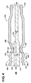
図7は本発明の別の局面に従い構成された多層ガスケット610を示す。類似のものは600番台が付けられて同様の参照番号で示される。ガスケット610は前記のものと異なり、単一の機能層614を有する。機能層614は概して機能層14や214と同様に形作られる。したがって、機能層614は、フル押圧封止ビード628を有し、このフルビード628は開口622から半径方向外側に、かつ面630に沿った内周部641から半径方向外側に形成される。機能層は外周部363まで延在するよう形成されるハーフビード634を有し、ビード628および634は、同じ方向に面630から軸方向外側に面する。
FIG. 7 illustrates a
ガスケット610はさらに機能層614の面630に部分的に沿って配置されるよう構成される距離層616を含む。距離層616の第1の部分648は、機能層614の開口622と実質的に同一平面にある開口624を形成し、第1の部分648は第1の厚さ(t1)を有し、その厚さt1は距離層616の最も厚い部分である。第1の部分648は開口624から半径方向外側に、第2の部分650に移行するある段差まで延在し、第2の部分650は厚さt1より小さい第2の厚さ(t2)を有する。第2の部分650は、開口622と機能層614のフルビード628との間から始まるよう構成されており、ここでは開口622とフルビード628とのおよそ中ほどから始まって示されている。第2の部分650はフルビード628を越えて外周654まで延在し、外周654はフルビード628と機能層614のハーフビード634との間で終端し、ここではフルビード628およびハーフビード634のおよそ中ほどで終端するよう示される。第2の部分650はフルビード628にわたって延在しているが、フルビード628の外形と一致しており、それによりフルビード628と対応する当接で波状となる。したがって、ガスケット610は、開口622およびフルビード628間の第1の部分648の第1の厚さt1にわたって、軸方向断面から見て最も厚い領域を有する。さらに、ガスケット610は軸方向断面から見て中間の厚さ領域を有し、これは開口622とフルビード628とのおよそ中ほどから始まり、フルビード628とハーフビード634とのおよそ中ほどまで延在する第2の部分650の第2の厚さt2にわたる。さらに、ガスケット610は軸方向断面から見て最小の厚さ領域を有し、これはフルビード628とハーフビード634とのおよそ中ほどから始まり、外周部636まで延在する機能層614にわたる。こうして、最小の厚さ領域は機能層614からのみなる。
The
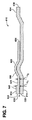
図8は本発明の別の局面に従い構成された多層ガスケット710を示す。類似のものは700番台が付けられて同様の参照番号で示される。ガスケット710は、機能層614と同様に形作られる、単一の機能層714を有する。したがって、機能層714はフル押圧封止ビード728を有し、封止ビード728は開口722から半径方向外側にかつ面730に沿った内周部741から半径方向外側に形成される。機能層はさらに外周部736まで延在するよう形成されるハーフビード734を有し、ビード728および734は同じ方向に面730から軸方向外側に面する。
FIG. 8 illustrates a multi-layer gasket 710 constructed in accordance with another aspect of the present invention. Similar ones are numbered 700 and are indicated with similar reference numbers. The gasket 710 has a single
ガスケット710はさらに、距離層616と同様に形作られる距離層716を含む。したがって、距離層716の第1の部分748は、機能層714の開口722と実質的に同一平面にある開口724を有し、第1の部分748は第1の厚さ(t1)を有し、その厚さt1は距離層716の最も厚い部分である。第1の部分748は開口724から半径方向外側に、第2の部分750に移行するある段差まで延在し、第2の部分750は厚さt1より小さい第2の厚さ(t2)を有する。第2の部分750は、開口722と機能層714のフルビード728との間から始まるよう構成されており、ここでは開口722とフルビード628とのおよそ中ほどから始まって示されている。第2の部分750はフルビード728を越えて外周754まで延在し、外周754はフルビード728と機能層714のハーフビード734との間で終端し、ここではフルビード728およびハーフビード734のおよそ中ほどで終端するよう示される。しかし、前の距離層616と異なり、距離層は機能層614の反対側に対して配置される。そのため、第2の部分750はフルビード728の谷にわたって延在する平たい平坦な構造であり、フルビード728と外形形状が一致しない。したがって、第2の部分750は一致せずに、フルビード728の波を横切る。前のガスケット610と同様に、ガスケット710は、開口722およびフルビード728間の第1の部分748の第1の厚さt1にわたって、軸方向断面から見て最も厚い領域を有する。さらに、ガスケット710は軸方向断面から見て中間の厚さ領域を有し、これは開口722とフルビード728とのおよそ中ほどから始まり、フルビード728とハーフビード734とのおよそ中ほどまで延在する第2の部分750の第2の厚さt2にわたる。さらに、ガスケット710は軸方向断面から見て最小の厚さ領域を有し、これはフルビード728とハーフビード734とのおよそ中ほどから始まる機能層714にわたり、かつハーフビード734にわたって延在する。そのため、機能層614と同様に、最小の厚さ領域は機能層714のみからなる。
The gasket 710 further includes a
図9は本発明のさらに別の局面に従い構成された多層ガスケット810を示す。類似のものは800番台が付けられて同様の参照番号で示される。ガスケット810は機能層614や714と同様に形作られる単一の機能層814を有するが、機能層は内周部841に段差部を有する。他の態様では、機能層814は機能層614や714と同様である。したがって、機能層814はフル押圧封止ビード828を有し、封止ビード828は開口822から半径方向外側に、かつ面830に沿って部分的在る内周部841から半径方向外側に形成され、段差部は面830から、フルビード828と同じ方向に軸方向外側に延在するが、フルビード828の頂842までは延在しない。したがって、段差部の上面は、面830とフルビード828の頂842に接する面との間にある。機能層814は外周部836に延在するよう形成されるハーフビード834も含み、ビード828および834は同じ方向に面830から外側に面する。
FIG. 9 shows a
ガスケット810はさらに、距離層716と同様に形作られる距離層816を含む。したがって、距離層816の第1の部分848は、機能層814の開口822と実質的に同一平面にある開口824を形成し、第1の部分848は第1の厚さ(t1)を有し、その厚さt1は距離層816の最も厚い部分である。第1の部分848は開口824から半径方向外側に、第2の部分850に移行するある段差まで延在し、第2の部分850は厚さt1より小さい第2の厚さ(t2)を有する。第2の部分850は、開口822と機能層814のフルビード828との間から始まるよう構成されており、ここでは開口822とフルビード828とのおよそ中ほどから始まって示されている。第2の部分850はフルビード828を越えて外周854まで延在し、外周854はフルビード828と機能層814のハーフビード834との間で終端し、ここではフルビード828およびハーフビード834のおよそ中ほどで終端するよう示される。したがって、距離層716と同様に、距離層816は、フルビード828およびハーフビード834が延在する機能層814の反対側に当接するよう配置されている。ガスケット810がガスケット710と大きく異なるのは、段差のある第1の厚さt1の第1の部分848が、機能層814に対向し、かつその段差領域で受入れられることである。前記のガスケット610や710と同様に、ガスケット810は開口822およびフルビード828間の第1の部分848の第1の厚さt1にわたって、軸方向断面から見て最も厚い領域を有する。さらに、ガスケット810は軸方向断面から見て中間の厚さ領域を有し、これは開口822とフルビード828とのおよそ中ほどから始まり、フルビード828とハーフビード834とのおよそ中ほどまで延在する第2の部分850の第2の厚さt2にわたる。さらに、ガスケット810は軸方向断面から見て最小の厚さ領域を有し、これはフルビード828とハーフビード834とのおよそ中ほどから始まり、ハーフビード834にわたって延在する。そのため、最小の厚さ領域は機能層814のみからなる。
The
図10は、本発明のさらに別の局面に従い構成された多層ガスケット910を示す。類似のものは900番台が付けられて同様の参照番号で示される。ガスケット910は3つの機能層912、912′および914と、距離層916とを有する。機能層912および914は、機能層12および14について上記と同じ構成および配置を本質的に有する。したがって、機能層912および914は距離層916の対向する側918および920に当接するよう配置され、距離層916は機能層912および914との間で挟持される。機能層912′は機能層912に重なり、当接する。機能層912、912′および914の各々は、距離層916の開口924と位置合わせされるよう寸法決めされている開口922を有し、それぞれの開口はシリンダ孔926と位置合わせされるよう、互いに対して配置される。機能層912および914の各々は、層912および914の面930から外方向に延在するフル押圧封止ビード928を有し、シリンダ孔926に対する気体気密封止の確立を容易にする。機能層912’はフル押圧ビード928′を有し、これは他の機能ビード928と同様に寸法決めされ、機能層912の機能ビード928と対向して配置されるよう構成されている。
FIG. 10 shows a
距離層916は、半径方向断面で見て対称な幾何学的形状を有して構成されるのではなく、半径方向断面から見て非対称の幾何学的形状を有して構成される。図1の実施例と同様に、各側918および920は第1の厚さ(t1)を有する第1の部分948に沿って、開口924から半径方向外側に延在し、厚さt1は距離層916の最も厚い部分である。第1の部分948は第1の厚さt1より小さい第2の厚さ(t2)を有する第2の部分950まで半径方向外側に延在し、第2の部分950は、所定の距離だけ、第3の部分952まで半径方向外側に延在し、第3の部分952の第3の厚さ(t3)はt2より小さい。第3の部分952はたとえばオイルポートまたは冷却剤チャンバ35のような流体通路の封止を容易にする開口54に延在する。第1の部分948および第2の部分950のそれぞれの厚さt1およびt2は、半径方向断面から見て、互いにずれている。そのため、距離層916の対向する側に異なる段差の高さが与えられる。たとえば、一方側に第1の段差高さ(S1)があり、反対側に段差高さ(S2)があり、S1はS2より大きい。好ましい実施例において、S1はS2の高さの2倍であるのに対して、ビード928および928′の高さは概して同じである。段差S1およびS2の相対する高さは他の態様に構成でき、ビード928および928′の相対的高さも他の態様に構成できることは理解されるであろう。
The
組立てられると、当接する機能層928および928′はそれぞれのフルビード928および928′が互いに鏡映の関係に並ぶよう配置されており、それぞれの頂942および942′は互いに反対方向に向かう。ガスケット910は、第2の部分950に当接するよう配置されている、反対方向に向かうフルビードを有する2つの当接機能層912および912と、第2の部分950の反対側に当接するよう配置されているフルビードを有する第3の機能層914とを有することにより、使用の際にシリンダヘッドとエンジンブロックとの間で形成されるより大きい動的ギャップは、シリンダ孔926からの気体の漏れに対して封止可能である。
When assembled, the abutting
本発明は上に示される教示に照らして、多くの変形および変更が可能であることは明らかである。したがって、特許請求の範囲内において、本発明は具体的に記載されている以外の態様で実施できることは理解されるべきである。 Obviously, many modifications and variations of the present invention are possible in light of the above teachings. Therefore, it is to be understood that, within the scope of the appended claims, the invention may be practiced otherwise than as specifically described.
Claims (14)
外周およびシリンダ孔を囲むよう構成されている開口を形成する内周、ならびに前記開口から半径方向外側にかつ前記開口を円周状に囲むフル押圧ビードを有する金属機能層を備え、前記フル押圧ビードは前記機能層の面から所定の第1の距離外れて延在し、
少なくとも2つの材料片を有する金属距離層を備え、1つの前記材料片は、前記機能層の前記開口と位置合わせされるよう構成されている開口まで延在する、第1の厚さを有する第1の径部分と、前記第1の径部分から半径方向外側に延在し、前記フル押圧ビードとならぶ第2の径部分とを有し、前記第2の径部分は前記第1の厚さより小さい第2の厚さを有し、他の前記材料片は、前記第2の径部分から半径方向外側に延在し、前記第2の厚さより小さい第3の厚さを有する第3の径部分を有し、
前記機能層または前記距離層の少なくとも一方によって設けられる押圧リミッタを備え、前記押圧リミッタは前記フル押圧ビードが金属ヘッドとエンジンブロックとの間で完全に平たくされるのを防ぎ、前記機能層にある前記押圧リミッタは、半径方向断面から見て波状の形状を有し、頂は前記機能層の対向側で互いに反対方向に延在し、前記波状の形状は前記フル押圧ビードに隣接する前記機能層開口に対して円周状に延在して前記距離層の前記第1の径部分と係合し、前記距離層にある前記押圧リミッタは、前記第2の径部分に隣接する第3の径部分を少なくとも1つ有し、前記第2の径部分は前記第1の部分と前記第3の径部分との間にある、多層金属静的シリンダヘッドガスケット。 A multilayer metal static cylinder head gasket configured to establish a seal between a cylinder head and an engine block,
An inner periphery forming an opening configured to surround the outer periphery and the cylinder hole, and a metal functional layer having a full pressing bead radially outward from the opening and circumferentially surrounding the opening, the full pressing bead Extends away from the surface of the functional layer by a predetermined first distance ;
A metal distance layer having at least two pieces of material, the one piece of material having a first thickness extending to an opening configured to be aligned with the opening of the functional layer; 1 and diameter portion extending radially outward from said first diameter portion, said and a second diameter portion alongside the full pressing bead, said second diameter portion than the first thickness A third diameter having a small second thickness and the other piece of material extending radially outward from the second diameter portion and having a third thickness less than the second thickness. Has a part,
A pressure limiter provided by at least one of the functional layer or the distance layer, the pressure limiter being in the functional layer to prevent the full pressure bead from being completely flattened between the metal head and the engine block; The pressing limiter has a wavy shape as viewed from a radial cross section, the tops extend in opposite directions on opposite sides of the functional layer, and the wavy shape is adjacent to the full pressing bead. The pressing limiter in the distance layer extends circumferentially with respect to the opening and engages with the first diameter portion of the distance layer, and the third diameter is adjacent to the second diameter portion. at least one has a portion, the second diameter portion is between the third diameter portion and said first portion, the multilayered metal static cylinder head gasket.
Applications Claiming Priority (7)
| Application Number | Priority Date | Filing Date | Title |
|---|---|---|---|
| US2831708P | 2008-02-13 | 2008-02-13 | |
| US61/028,317 | 2008-02-13 | ||
| US10968208P | 2008-10-30 | 2008-10-30 | |
| US61/109,682 | 2008-10-30 | ||
| US12/370,253 US8632077B2 (en) | 2008-02-13 | 2009-02-12 | Multilayer static gasket with bead compression limiter |
| US12/370,253 | 2009-02-12 | ||
| PCT/US2009/034008 WO2009102921A2 (en) | 2008-02-13 | 2009-02-13 | Multilayer static gasket with bead compression limiter |
Publications (3)
| Publication Number | Publication Date |
|---|---|
| JP2011511916A JP2011511916A (en) | 2011-04-14 |
| JP2011511916A5 JP2011511916A5 (en) | 2012-03-22 |
| JP5384531B2 true JP5384531B2 (en) | 2014-01-08 |
Family
ID=40938248
Family Applications (1)
| Application Number | Title | Priority Date | Filing Date |
|---|---|---|---|
| JP2010546909A Expired - Fee Related JP5384531B2 (en) | 2008-02-13 | 2009-02-13 | Multilayer static gasket with bead pressing limiter |
Country Status (6)
| Country | Link |
|---|---|
| US (2) | US8632077B2 (en) |
| EP (1) | EP2245343B1 (en) |
| JP (1) | JP5384531B2 (en) |
| KR (1) | KR101486873B1 (en) |
| CN (1) | CN102027271B (en) |
| WO (1) | WO2009102921A2 (en) |
Families Citing this family (14)
| Publication number | Priority date | Publication date | Assignee | Title |
|---|---|---|---|---|
| US8336888B2 (en) * | 2009-10-22 | 2012-12-25 | Dana Automotive Systems Group, Llc | Gasket with engine liner accomodation |
| JP5801080B2 (en) * | 2011-03-30 | 2015-10-28 | ニチアス株式会社 | Cylinder head gasket |
| US9695936B2 (en) | 2011-04-14 | 2017-07-04 | Federal-Mogul Llc | Multilayer metal gasket with bead on stopper |
| US9027935B2 (en) * | 2012-01-31 | 2015-05-12 | Federal-Mogul Corporation | Gasket with a compression limiter |
| US9939066B2 (en) * | 2013-03-14 | 2018-04-10 | Federal-Mogul Llc | Elastic sealing member radially inwardly of primary sealing bead |
| JP6259276B2 (en) * | 2013-12-18 | 2018-01-10 | Nok株式会社 | Cylinder head gasket and manufacturing method thereof |
| US9243584B2 (en) | 2014-02-13 | 2016-01-26 | Federal-Mogul Corporation | Cylinder head gasket with compression control features |
| US20150226153A1 (en) * | 2014-02-13 | 2015-08-13 | Federal Mogul Corporation | Cylinder head gasket for high load and motion applications |
| US10359003B2 (en) * | 2014-06-23 | 2019-07-23 | Tenneco Inc. | Cylinder head gasket with compression limiter and full bead loading |
| CN107250628A (en) * | 2014-12-19 | 2017-10-13 | 费德罗-莫格尔有限责任公司 | Multilayer static gasket, its include the wall and its construction method of barrier zones |
| KR20170095911A (en) | 2014-12-19 | 2017-08-23 | 페더럴-모걸 엘엘씨 | Multilayer static gasket, distance layer with improved stopper region therefor, and method of construction thereof |
| JP5971535B2 (en) * | 2015-02-05 | 2016-08-17 | 日本ガスケット株式会社 | gasket |
| CN105351110A (en) * | 2015-12-04 | 2016-02-24 | 广西玉柴机器股份有限公司 | Cylinder head gasket |
| US9964068B2 (en) * | 2016-02-25 | 2018-05-08 | Ford Global Technologies, Llc | Head gasket for an internal combustion engine |
Family Cites Families (59)
| Publication number | Priority date | Publication date | Assignee | Title |
|---|---|---|---|---|
| EP0459060B1 (en) | 1990-05-28 | 1995-02-08 | Nihon Metal Gasket Co. Ltd | Metallic gasket |
| JP2935545B2 (en) | 1990-07-16 | 1999-08-16 | 日本リークレス工業株式会社 | Metal gasket |
| EP0485693B1 (en) | 1990-11-14 | 1994-12-21 | Friedhelm Stecher | Cylinder-head gasket and manufacturing method |
| JP2989282B2 (en) | 1991-01-09 | 1999-12-13 | 日本ガスケット株式会社 | Metal gasket |
| JP3142155B2 (en) * | 1991-08-21 | 2001-03-07 | 日本ガスケット株式会社 | Metal gasket |
| JPH087170Y2 (en) * | 1992-02-18 | 1996-03-04 | 石川ガスケット株式会社 | Half bead of laminated metal gasket |
| JP2753779B2 (en) | 1992-02-18 | 1998-05-20 | 日本メタルガスケット 株式会社 | Molding method of metal gasket and stopper |
| JPH05340476A (en) | 1992-06-09 | 1993-12-21 | Japan Metal Gasket Co Ltd | Metallic gasket |
| DE4219709C2 (en) * | 1992-06-16 | 2001-07-12 | Reinz Dichtungs Gmbh | Metallic flat gasket |
| US5618049A (en) * | 1993-06-04 | 1997-04-08 | Japan Metal Gasket Co., Ltd. | Metallic gasket |
| JP3581162B2 (en) * | 1993-07-07 | 2004-10-27 | 日本リークレス工業株式会社 | Manufacturing method of metal gasket |
| JPH07224939A (en) * | 1994-02-09 | 1995-08-22 | Nippon Reinz Co Ltd | Metal gasket |
| JP3230966B2 (en) | 1995-10-09 | 2001-11-19 | 日本ガスケット株式会社 | Metal gasket |
| DE19605871C2 (en) * | 1996-02-17 | 1998-01-29 | Elringklinger Gmbh | Metallic cylinder head gasket |
| DE19606382A1 (en) * | 1996-02-21 | 1997-09-04 | Elringklinger Gmbh | Cylinder head gasket with a gasket plate with several sheet metal layers |
| DE19611092C2 (en) | 1996-03-21 | 2001-04-26 | Elringklinger Gmbh | Method for applying a cant to a metal layer of a cylinder head gasket and cylinder head gasket |
| DE19641491A1 (en) | 1996-10-09 | 1998-04-23 | Payen Goetze Gmbh | Automotive gasket spacer layer fabricated from sintered powder |
| DE19654283A1 (en) * | 1996-12-24 | 1998-06-25 | Reinz Dichtungs Gmbh | Metallic flat gasket |
| JP3738121B2 (en) * | 1997-11-07 | 2006-01-25 | 日本ガスケット株式会社 | Metal gasket |
| DE19756431C1 (en) * | 1997-12-18 | 1999-06-02 | Elringklinger Gmbh | Cylinder head gasket for internal combustion engine |
| JP4180144B2 (en) | 1998-04-10 | 2008-11-12 | 日本メタルガスケット株式会社 | Metal gasket |
| JP4032270B2 (en) * | 1998-09-18 | 2008-01-16 | 大豊工業株式会社 | Cylinder head gasket |
| JP4413301B2 (en) * | 1999-02-05 | 2010-02-10 | 日本メタルガスケット株式会社 | Metal gasket |
| US6450504B2 (en) * | 1999-05-11 | 2002-09-17 | Elringklinger Ag | Cylinder head gasket |
| JP2001012611A (en) * | 1999-06-30 | 2001-01-16 | Nippon Gasket Co Ltd | Metal gasket |
| JP3751786B2 (en) | 1999-12-27 | 2006-03-01 | 石川ガスケット株式会社 | Metal laminated gasket |
| JP2001241551A (en) * | 2000-02-25 | 2001-09-07 | Taiho Kogyo Co Ltd | Cylinder head gasket |
| DE10018290B4 (en) * | 2000-04-13 | 2004-07-15 | Elringklinger Ag | Cylinder head gasket and process for its manufacture |
| JP2001295939A (en) | 2000-04-17 | 2001-10-26 | Taiho Kogyo Co Ltd | Cylinder head gasket |
| DE10019715B4 (en) * | 2000-04-20 | 2006-01-05 | Elringklinger Ag | Method for applying an elevation to a metal layer of a cylinder head gasket and cylinder head gasket |
| DE10021975A1 (en) * | 2000-05-05 | 2001-11-22 | Reinz Dichtungs Gmbh | Cylinder head gasket includes plastic in ring seal stopper elevation, to impart controlled degrees of resilience and plasticity |
| DE20121984U1 (en) | 2000-06-15 | 2003-11-27 | Reinz-Dichtungs-Gmbh & Co. Kg | gasket |
| DE10029352B4 (en) * | 2000-06-15 | 2007-01-04 | Reinz-Dichtungs-Gmbh & Co. Kg | gasket |
| JP2002031238A (en) | 2000-07-18 | 2002-01-31 | Japan Metal Gasket Co Ltd | Metal gasket |
| US20020153666A1 (en) * | 2000-10-17 | 2002-10-24 | Gunther Unseld | Metal flat gasket |
| DE20021017U1 (en) * | 2000-12-12 | 2001-02-22 | Reinz Dichtungs Gmbh U Co Kg | Cylinder head gasket |
| DE10117178B4 (en) * | 2001-04-05 | 2006-11-09 | Elringklinger Ag | Cylinder head gasket |
| DE10143431B4 (en) * | 2001-09-05 | 2006-02-02 | Elringklinger Ag | Cylinder head gasket |
| EP1298364B1 (en) | 2001-09-29 | 2005-06-22 | ElringKlinger AG | Metallic cylinder head gasket |
| US6769696B2 (en) * | 2001-09-29 | 2004-08-03 | Elringklinger Ag | At least substantially metallic cylinder head gasket |
| DE10310014B4 (en) * | 2003-02-28 | 2009-09-10 | Reinz-Dichtungs-Gmbh | Cylinder head gasket |
| JP2004278711A (en) | 2003-03-17 | 2004-10-07 | Nippon Leakless Corp | Metal gasket for cylinder head |
| US6951338B2 (en) * | 2003-03-21 | 2005-10-04 | Dana Corporation | Cylinder head gasket |
| FR2860553B1 (en) | 2003-10-02 | 2006-02-24 | Meillor Sa | MULTILAYER CYLINDER HEAD COMPRISING AT LEAST ONE FREEZER HOLDER |
| JP2005180579A (en) | 2003-12-19 | 2005-07-07 | Japan Metal Gasket Co Ltd | Metallic gasket |
| US7204491B2 (en) * | 2004-01-23 | 2007-04-17 | Koichi Hatamura | Metal gasket |
| DE102004012905A1 (en) * | 2004-03-17 | 2005-10-13 | Elringklinger Ag | Cylinder head gasket |
| US7374177B2 (en) * | 2004-09-21 | 2008-05-20 | Federal-Mogul World Wide, Inc. | Enhanced multilayer metal gasket |
| FR2875570B1 (en) * | 2004-09-21 | 2007-02-16 | Meillor Sa Sa | JOINT COMPRISING AT LEAST ONE RIB INCORPORATING A CRUSHING LIMITER |
| DE102004047540A1 (en) * | 2004-09-30 | 2006-04-20 | Elringklinger Ag | Flat gasket and method for producing a flat gasket |
| US7287757B2 (en) * | 2005-06-28 | 2007-10-30 | Dana Corporation | Optimized wave bead with full bead design |
| JP2007139177A (en) * | 2005-10-20 | 2007-06-07 | Japan Metal Gasket Co Ltd | Gasket |
| JP4875356B2 (en) * | 2005-10-24 | 2012-02-15 | 日本メタルガスケット株式会社 | gasket |
| EP1985896B1 (en) * | 2007-04-24 | 2012-12-12 | REINZ-Dichtungs-GmbH | Metal flat gasket |
| US7559556B2 (en) * | 2006-01-06 | 2009-07-14 | Dana Automotive Systems Group, Llc | MLS gasket compression limiter |
| JP4499051B2 (en) | 2006-03-20 | 2010-07-07 | トヨタ自動車株式会社 | Cylinder head gasket |
| DE102006021499A1 (en) * | 2006-05-09 | 2007-11-15 | Elringklinger Ag | Flat gasket, in particular cylinder head gasket |
| DE102006032895A1 (en) * | 2006-07-15 | 2008-01-24 | Elringklinger Ag | gasket |
| JP4909753B2 (en) | 2007-01-31 | 2012-04-04 | 株式会社豊田自動織機 | Cylinder head gasket |
-
2009
- 2009-02-12 US US12/370,253 patent/US8632077B2/en not_active Expired - Fee Related
- 2009-02-13 JP JP2010546909A patent/JP5384531B2/en not_active Expired - Fee Related
- 2009-02-13 EP EP20090711083 patent/EP2245343B1/en not_active Not-in-force
- 2009-02-13 WO PCT/US2009/034008 patent/WO2009102921A2/en active Application Filing
- 2009-02-13 KR KR1020107020418A patent/KR101486873B1/en active IP Right Grant
- 2009-02-13 CN CN200980112520.9A patent/CN102027271B/en not_active Expired - Fee Related
-
2013
- 2013-12-17 US US14/108,709 patent/US8783692B2/en not_active Expired - Fee Related
Also Published As
| Publication number | Publication date |
|---|---|
| EP2245343A4 (en) | 2012-01-18 |
| CN102027271A (en) | 2011-04-20 |
| US8632077B2 (en) | 2014-01-21 |
| WO2009102921A2 (en) | 2009-08-20 |
| US20090200752A1 (en) | 2009-08-13 |
| WO2009102921A3 (en) | 2009-11-12 |
| EP2245343A2 (en) | 2010-11-03 |
| US8783692B2 (en) | 2014-07-22 |
| KR101486873B1 (en) | 2015-01-28 |
| JP2011511916A (en) | 2011-04-14 |
| CN102027271B (en) | 2014-03-12 |
| US20140103610A1 (en) | 2014-04-17 |
| KR20100132002A (en) | 2010-12-16 |
| EP2245343B1 (en) | 2015-04-22 |
Similar Documents
| Publication | Publication Date | Title |
|---|---|---|
| JP5384531B2 (en) | Multilayer static gasket with bead pressing limiter | |
| JP5917571B2 (en) | Multilayer static gasket with secondary compression limiter | |
| US8100409B2 (en) | Metallic cylinder head gasket | |
| US10006403B2 (en) | Cylinder head gasket | |
| KR101707893B1 (en) | Cylinder head gasket assembly | |
| US10443731B2 (en) | Gasket component with half-stop and method of manufacturing | |
| KR102004574B1 (en) | Metal gasket | |
| KR101909566B1 (en) | Multilayer metal gasket with bead on stopper bead on stopper | |
| US9518660B2 (en) | Bimetallic static gasket and method of construction thereof | |
| JP2011525226A (en) | Flat gasket | |
| JPH05240354A (en) | Metal layered gasket | |
| US10119494B2 (en) | Multi-layer gasket assembly | |
| EP3114376B1 (en) | Gasket component with half-stop and method of manufacturing | |
| JP4787343B2 (en) | Metal gasket and method for manufacturing the same | |
| JP5023102B2 (en) | Metal gasket and method for manufacturing the same | |
| JPH06337069A (en) | Metallic gasket |
Legal Events
| Date | Code | Title | Description |
|---|---|---|---|
| A521 | Request for written amendment filed |
Free format text: JAPANESE INTERMEDIATE CODE: A523 Effective date: 20120201 |
|
| A621 | Written request for application examination |
Free format text: JAPANESE INTERMEDIATE CODE: A621 Effective date: 20120201 |
|
| A977 | Report on retrieval |
Free format text: JAPANESE INTERMEDIATE CODE: A971007 Effective date: 20130214 |
|
| A131 | Notification of reasons for refusal |
Free format text: JAPANESE INTERMEDIATE CODE: A131 Effective date: 20130305 |
|
| A601 | Written request for extension of time |
Free format text: JAPANESE INTERMEDIATE CODE: A601 Effective date: 20130531 |
|
| A602 | Written permission of extension of time |
Free format text: JAPANESE INTERMEDIATE CODE: A602 Effective date: 20130607 |
|
| A521 | Request for written amendment filed |
Free format text: JAPANESE INTERMEDIATE CODE: A523 Effective date: 20130704 |
|
| TRDD | Decision of grant or rejection written | ||
| A01 | Written decision to grant a patent or to grant a registration (utility model) |
Free format text: JAPANESE INTERMEDIATE CODE: A01 Effective date: 20130903 |
|
| A61 | First payment of annual fees (during grant procedure) |
Free format text: JAPANESE INTERMEDIATE CODE: A61 Effective date: 20131002 |
|
| R150 | Certificate of patent or registration of utility model |
Ref document number: 5384531 Country of ref document: JP Free format text: JAPANESE INTERMEDIATE CODE: R150 Free format text: JAPANESE INTERMEDIATE CODE: R150 |
|
| R250 | Receipt of annual fees |
Free format text: JAPANESE INTERMEDIATE CODE: R250 |
|
| R250 | Receipt of annual fees |
Free format text: JAPANESE INTERMEDIATE CODE: R250 |
|
| R250 | Receipt of annual fees |
Free format text: JAPANESE INTERMEDIATE CODE: R250 |
|
| R250 | Receipt of annual fees |
Free format text: JAPANESE INTERMEDIATE CODE: R250 |
|
| LAPS | Cancellation because of no payment of annual fees |