JP5384101B2 - Electric appliances operated by batteries - Google Patents
Electric appliances operated by batteries Download PDFInfo
- Publication number
- JP5384101B2 JP5384101B2 JP2008508890A JP2008508890A JP5384101B2 JP 5384101 B2 JP5384101 B2 JP 5384101B2 JP 2008508890 A JP2008508890 A JP 2008508890A JP 2008508890 A JP2008508890 A JP 2008508890A JP 5384101 B2 JP5384101 B2 JP 5384101B2
- Authority
- JP
- Japan
- Prior art keywords
- electrically conductive
- housing
- conductive member
- battery cover
- razor
- Prior art date
- Legal status (The legal status is an assumption and is not a legal conclusion. Google has not performed a legal analysis and makes no representation as to the accuracy of the status listed.)
- Active
Links
Images


Classifications
-
- H—ELECTRICITY
- H01—ELECTRIC ELEMENTS
- H01M—PROCESSES OR MEANS, e.g. BATTERIES, FOR THE DIRECT CONVERSION OF CHEMICAL ENERGY INTO ELECTRICAL ENERGY
- H01M50/00—Constructional details or processes of manufacture of the non-active parts of electrochemical cells other than fuel cells, e.g. hybrid cells
- H01M50/20—Mountings; Secondary casings or frames; Racks, modules or packs; Suspension devices; Shock absorbers; Transport or carrying devices; Holders
-
- A—HUMAN NECESSITIES
- A61—MEDICAL OR VETERINARY SCIENCE; HYGIENE
- A61C—DENTISTRY; APPARATUS OR METHODS FOR ORAL OR DENTAL HYGIENE
- A61C17/00—Devices for cleaning, polishing, rinsing or drying teeth, teeth cavities or prostheses; Saliva removers; Dental appliances for receiving spittle
- A61C17/16—Power-driven cleaning or polishing devices
- A61C17/22—Power-driven cleaning or polishing devices with brushes, cushions, cups, or the like
- A61C17/225—Handles or details thereof
-
- B—PERFORMING OPERATIONS; TRANSPORTING
- B26—HAND CUTTING TOOLS; CUTTING; SEVERING
- B26B—HAND-HELD CUTTING TOOLS NOT OTHERWISE PROVIDED FOR
- B26B19/00—Clippers or shavers operating with a plurality of cutting edges, e.g. hair clippers, dry shavers
- B26B19/38—Details of, or accessories for, hair clippers, or dry shavers, e.g. housings, casings, grips, guards
- B26B19/3853—Housing or handle
-
- B—PERFORMING OPERATIONS; TRANSPORTING
- B26—HAND CUTTING TOOLS; CUTTING; SEVERING
- B26B—HAND-HELD CUTTING TOOLS NOT OTHERWISE PROVIDED FOR
- B26B19/00—Clippers or shavers operating with a plurality of cutting edges, e.g. hair clippers, dry shavers
- B26B19/38—Details of, or accessories for, hair clippers, or dry shavers, e.g. housings, casings, grips, guards
- B26B19/3873—Electric features; Charging; Computing devices
-
- B—PERFORMING OPERATIONS; TRANSPORTING
- B26—HAND CUTTING TOOLS; CUTTING; SEVERING
- B26B—HAND-HELD CUTTING TOOLS NOT OTHERWISE PROVIDED FOR
- B26B21/00—Razors of the open or knife type; Safety razors or other shaving implements of the planing type; Hair-trimming devices involving a razor-blade; Equipment therefor
- B26B21/08—Razors of the open or knife type; Safety razors or other shaving implements of the planing type; Hair-trimming devices involving a razor-blade; Equipment therefor involving changeable blades
- B26B21/14—Safety razors with one or more blades arranged transversely to the handle
- B26B21/38—Safety razors with one or more blades arranged transversely to the handle with provision for reciprocating the blade by means other than rollers
-
- B—PERFORMING OPERATIONS; TRANSPORTING
- B26—HAND CUTTING TOOLS; CUTTING; SEVERING
- B26B—HAND-HELD CUTTING TOOLS NOT OTHERWISE PROVIDED FOR
- B26B21/00—Razors of the open or knife type; Safety razors or other shaving implements of the planing type; Hair-trimming devices involving a razor-blade; Equipment therefor
- B26B21/40—Details or accessories
- B26B21/52—Handles, e.g. tiltable, flexible
- B26B21/526—Electric features
-
- H—ELECTRICITY
- H01—ELECTRIC ELEMENTS
- H01M—PROCESSES OR MEANS, e.g. BATTERIES, FOR THE DIRECT CONVERSION OF CHEMICAL ENERGY INTO ELECTRICAL ENERGY
- H01M50/00—Constructional details or processes of manufacture of the non-active parts of electrochemical cells other than fuel cells, e.g. hybrid cells
- H01M50/20—Mountings; Secondary casings or frames; Racks, modules or packs; Suspension devices; Shock absorbers; Transport or carrying devices; Holders
- H01M50/204—Racks, modules or packs for multiple batteries or multiple cells
- H01M50/207—Racks, modules or packs for multiple batteries or multiple cells characterised by their shape
- H01M50/213—Racks, modules or packs for multiple batteries or multiple cells characterised by their shape adapted for cells having curved cross-section, e.g. round or elliptic
-
- H—ELECTRICITY
- H01—ELECTRIC ELEMENTS
- H01R—ELECTRICALLY-CONDUCTIVE CONNECTIONS; STRUCTURAL ASSOCIATIONS OF A PLURALITY OF MUTUALLY-INSULATED ELECTRICAL CONNECTING ELEMENTS; COUPLING DEVICES; CURRENT COLLECTORS
- H01R13/00—Details of coupling devices of the kinds covered by groups H01R12/70 or H01R24/00 - H01R33/00
- H01R13/02—Contact members
- H01R13/20—Pins, blades, or sockets shaped, or provided with separate member, to retain co-operating parts together
- H01R13/213—Pins, blades, or sockets shaped, or provided with separate member, to retain co-operating parts together by bayonet connection
-
- H—ELECTRICITY
- H01—ELECTRIC ELEMENTS
- H01R—ELECTRICALLY-CONDUCTIVE CONNECTIONS; STRUCTURAL ASSOCIATIONS OF A PLURALITY OF MUTUALLY-INSULATED ELECTRICAL CONNECTING ELEMENTS; COUPLING DEVICES; CURRENT COLLECTORS
- H01R13/00—Details of coupling devices of the kinds covered by groups H01R12/70 or H01R24/00 - H01R33/00
- H01R13/62—Means for facilitating engagement or disengagement of coupling parts or for holding them in engagement
- H01R13/625—Casing or ring with bayonet engagement
-
- H—ELECTRICITY
- H01—ELECTRIC ELEMENTS
- H01R—ELECTRICALLY-CONDUCTIVE CONNECTIONS; STRUCTURAL ASSOCIATIONS OF A PLURALITY OF MUTUALLY-INSULATED ELECTRICAL CONNECTING ELEMENTS; COUPLING DEVICES; CURRENT COLLECTORS
- H01R33/00—Coupling devices specially adapted for supporting apparatus and having one part acting as a holder providing support and electrical connection via a counterpart which is structurally associated with the apparatus, e.g. lamp holders; Separate parts thereof
- H01R33/05—Two-pole devices
- H01R33/46—Two-pole devices for bayonet type base
-
- Y—GENERAL TAGGING OF NEW TECHNOLOGICAL DEVELOPMENTS; GENERAL TAGGING OF CROSS-SECTIONAL TECHNOLOGIES SPANNING OVER SEVERAL SECTIONS OF THE IPC; TECHNICAL SUBJECTS COVERED BY FORMER USPC CROSS-REFERENCE ART COLLECTIONS [XRACs] AND DIGESTS
- Y02—TECHNOLOGIES OR APPLICATIONS FOR MITIGATION OR ADAPTATION AGAINST CLIMATE CHANGE
- Y02E—REDUCTION OF GREENHOUSE GAS [GHG] EMISSIONS, RELATED TO ENERGY GENERATION, TRANSMISSION OR DISTRIBUTION
- Y02E60/00—Enabling technologies; Technologies with a potential or indirect contribution to GHG emissions mitigation
- Y02E60/10—Energy storage using batteries
Abstract
Description
本発明は、パーソナルケア電化製品、より具体的には、そのような電化製品のためのケースカバーに関する。 The present invention relates to personal care appliances, and more particularly to case covers for such appliances.
多くの小型電池操作による電化製品では、電池は、ユーザーにより置換可能で、カバーを有する開口部を通して蓄電池室に出し入れされる。 In many small battery-operated appliances, the battery is replaceable by the user and is moved into and out of the battery compartment through an opening with a cover.
電池が出て落ちないよう、カバーがなくならないよう、カバーを一定の場所に機械的に固定することが必要である。装置内での電池と電気回路との間の電気的接続を起こすことも必要である。 It is necessary to mechanically fix the cover in a certain place so that the battery does not fall out and the cover does not disappear. It is also necessary to make an electrical connection between the battery and the electrical circuit within the device.
本発明は、小型電化製品のハウジングに電池カバーを固定するとともに、電池と電化製品の電子機器との間に信頼性の高い電気的接続をもたらすため、簡単で有効な機構を提供する。製造または組み立てが容易で経済的であるため、ごく少ない部品を含む閉鎖機構が好ましい。更に、いくつかの好ましい閉鎖機構は、小型で場所をとらないハウジングデザインで、及び/又は、電池カバーとハウジングとの間に線上の継目のない線を含むデザインで、使うのに適している。 The present invention provides a simple and effective mechanism for securing a battery cover to the housing of a small appliance and providing a reliable electrical connection between the battery and the electronics of the appliance. A closure mechanism with very few parts is preferred because it is easy and economical to manufacture or assemble. In addition, some preferred closure mechanisms are suitable for use in small, space-saving housing designs and / or in designs that include a seamless line on the line between the battery cover and the housing.
ある態様では、本発明は、内部壁を有するチャンバを画定するハウジングと、前記チャンバ内の電子機器と、電池カバーと、閉鎖機構と、を備え、前記電池カバー及び/又は前記ハウジングは、1以上の電池を含有するように構成される、電池操作による電化製品を特徴とする。閉鎖機構は、電池カバーに固定された第一の電気伝導性部材と、ハウジングの内部壁に固定され、第一の電気伝導性部材に係合するように構成された第二の電気伝導性部材とを含み、第一の電気伝導性部材と第二の電気伝導性部材との間の電気的接続を確立するととともに、電池カバーを、ハウジングに機械的に固定する。 In one aspect, the invention comprises a housing defining a chamber having an internal wall, an electronic device in the chamber, a battery cover, and a closure mechanism, wherein the battery cover and / or the housing is one or more. A battery-operated appliance configured to contain a battery of The closure mechanism includes a first electrically conductive member fixed to the battery cover and a second electrically conductive member fixed to the inner wall of the housing and configured to engage the first electrically conductive member. And establishing an electrical connection between the first and second electrically conductive members and mechanically securing the battery cover to the housing.
幾つかの実施例は、次の特徴の1以上を含み得る。第一及び第二の電気伝導性部材は、電池カバーがハウジングに対して回転することで、相互に係合するように構成され得る。例えば、第二の電気伝導性部材が、開放端部を有する周囲方向に延伸したスロットを含み、第一の電気伝導性部材が、回転中に開放端部を通ってスロット内に滑り込むように構成されたフックを含む。ハウジングの内部壁は略円筒状であってもよく、及び/又はハウジングの外表面と電池カバーは、略円筒状であってもよい。本発明での「略円筒状」とは、ハウジングと電池カバーが、それぞれ、例えば、隆起部、突出部、又は凹部といった円筒状ではない構成要素を含んでもよいことを意味し、及び/又は円筒状ではない長さに沿った領域を含んでもよいことを意味する。 Some embodiments may include one or more of the following features. The first and second electrically conductive members can be configured to engage each other as the battery cover rotates relative to the housing. For example, the second electrically conductive member includes a circumferentially extending slot having an open end, and the first electrically conductive member is configured to slide through the open end into the slot during rotation. Including hooks. The inner wall of the housing may be substantially cylindrical and / or the outer surface of the housing and the battery cover may be substantially cylindrical. By “substantially cylindrical” in the present invention is meant that the housing and the battery cover may each include non-cylindrical components such as, for example, ridges, protrusions, or recesses, and / or cylinders. It means that it may include a region along the length that is not in the shape.
第一及び第二の電気伝導性部材が係合するとき、第一の電気伝導性部材が、ハウジングと電池カバーとの間の軸力を適用するように構成されたバネ要素を含む。第一の電気伝導性部材が2以上のバネ要素を含み、各バネ要素が第一の電気伝導性部材と第二の電気伝導性部材との間の電気的接続をもたらすことが可能である。 When the first and second electrically conductive members engage, the first electrically conductive member includes a spring element configured to apply an axial force between the housing and the battery cover. The first electrically conductive member may include two or more spring elements, each spring element providing an electrical connection between the first electrically conductive member and the second electrically conductive member.
第一及び第二の電気伝導性部材は、電池カバーとハウジングのそれぞれに、スナップ嵌めで固定される。例えば、第二の電気伝導性部材は、ハウジングへの挿入に先立って圧縮され、放射状のバネ抵抗力を有するハウジングの内部壁に係合する、バネ部分を含むことが可能である。バネ部分は、略管形状であってもよい。第二の電気伝導性要素が、ハウジングの内部壁上の対応する切り下げに係合するように構成されている1以上の切り下げを含むことが可能である。 The first and second electrically conductive members are fixed to the battery cover and the housing by a snap fit. For example, the second electrically conductive member can include a spring portion that is compressed prior to insertion into the housing and engages the inner wall of the housing having a radial spring resistance. The spring portion may be substantially tubular. The second electrically conductive element can include one or more undercuts configured to engage corresponding undercuts on the inner wall of the housing.
第二の電気伝導性部材は、電化製品、例えば1以上の電源レールの、電子サブ組立体と電気的接続を得るように構成された部分を含んでもよい。各電源レールは、サブ組立体を係合するように組み立てられたクリップを含むことが可能で、この係合は、第二の電気伝導性部材をサブ組立体に機械的に固定することが可能である。 The second electrically conductive member may include a portion of an appliance, such as one or more power rails, configured to make electrical connection with the electronic subassembly. Each power rail can include a clip assembled to engage the subassembly, which engagement can mechanically secure the second electrically conductive member to the subassembly. It is.
第二の電気伝導性部材が、第一の電気伝導性部材上の対応する領域と機械的に係合するように構成された係合領域を含むことが可能で、第二の電気伝導性要素上の各切り下げが、係合領域の1つと軸方向に略直線状に並ぶことが可能である。 The second electrically conductive member can include an engagement region configured to mechanically engage a corresponding region on the first electrically conductive member, the second electrically conductive element Each of the upper cut-downs can be aligned substantially linearly with one of the engagement regions in the axial direction.
電化製品は、例えば、電動歯ブラシであることも、又は、電気的に作動する機能のカミソリであることも可能である。従って、電子機器は、電動歯ブラシの先端を駆動するように、又は、湿式剃毛用のカミソリの振動機能を駆動するように、構成され得る。 The electrical appliance can be, for example, an electric toothbrush or a razor with a function that operates electrically. Thus, the electronic device can be configured to drive the tip of an electric toothbrush or to drive the vibration function of a wet shaving razor.
一つの実施態様では、本発明は、電池操作による電化製品を特徴とし、それには、略円筒状の内部壁を有するチャンバを画定する略円筒状のハウジングを含んだカミソリ又は電動歯ブラシ、チャンバの内の電子機器、略円筒状の電池カバー、1以上の電池を含有するように構成されている電池カバー及び/又はハウジング、電池カバーに固定された第一の電気伝導性部材と、ハウジングの内部壁に固定され、ハウジングに対して電池カバーが回転する間、第一の電気伝導性部材に係合するように構成された第二の電気伝導性部材、とを含む閉鎖機構、などが挙げられる。それにより、第一の電気伝導性部材と第二の電気伝導性部材との間の電気的接続を確立するとともに、電池カバーをハウジングに機械的に固定する。 In one embodiment, the invention features a battery-operated appliance that includes a razor or electric toothbrush that includes a generally cylindrical housing defining a chamber having a generally cylindrical interior wall, An electronic device, a substantially cylindrical battery cover, a battery cover and / or housing configured to contain one or more batteries, a first electrically conductive member fixed to the battery cover, and an inner wall of the housing And a second electrically conductive member configured to engage the first electrically conductive member during rotation of the battery cover relative to the housing. This establishes an electrical connection between the first and second electrically conductive members and mechanically secures the battery cover to the housing.
図1を参照すると、電池式装置10が、円筒状のハウジング12と略円筒状の電池カバー14を含む。電池カバー14は、1以上の金属バネ要素16を略円筒状の金属受容部18に接合することによって、ハウジング12に取り付けられる。金属バネ要素16と金属受容部18は、図2〜4を参照して詳細には、論じない。
Referring to FIG. 1, a battery-powered device 10 includes a cylindrical housing 12 and a substantially cylindrical battery cover 14. The battery cover 14 is attached to the housing 12 by joining one or more
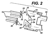
図2〜4には、2つのバネ要素が示されている。しかしながら、2以上またはそれより少ないバネ要素が使われてもよく、当該技術分野において当業者には理解されるであろう。一般的に、バネ要素が多く使われる程、電気的に信頼性が高く、電池カバーとハウジングとの間の接続がより強くなる。 2 to 4 show two spring elements. However, two or more spring elements may be used and will be understood by those skilled in the art. In general, the more spring elements are used, the higher the electrical reliability and the stronger the connection between the battery cover and the housing.
図2を参照すると、各バネ要素16は、1つの末端部にフック20を有する。各フックは、1以上の突出部22を含む。図1、4、及び5に示されるように、挿入、取り出し、フックの定着を確実にする突出部22と共に、フックは、受容部18内の対応するスロット24に受容され保持されるように組み立てられている。各スロット24は、電池カバーがハウジングに対して回転するに従ってフックをスロット内に導入するために、角度のついた壁26、28を有する引き込み部25を含む。スロット内のフックの係合は、電池カバーの確実な、寄り合わされた機械的な接続をハウジングにもたらす。
Referring to FIG. 2, each
バネ要素は、ハウジングの長軸線に沿って、バネ抵抗力を軸方向に適用するように設計されている。実施形態で示されるように、動作中にバネが伸びるに伴い、バネのS(エス)状の形(図4)が、このバネ抵抗力を生成する。従って、バネ要素がスロット内に動くと、バネ要素が伸ばされ、電池カバーとハウジングを一緒に引っ張る。電池カバーとハウジングとの、この弾力的な係合が、電池カバーとハウジングとの間の線上の継目のない線、及び、許容度などの他の形状の問題を補う。 The spring element is designed to apply a spring resistance axially along the long axis of the housing. As shown in the embodiment, as the spring stretches during operation, the S-shaped shape of the spring (FIG. 4) generates this spring resistance. Thus, as the spring element moves into the slot, the spring element is stretched and pulls the battery cover and housing together. This resilient engagement of the battery cover and the housing compensates for other shape problems such as the seamless line on the line between the battery cover and the housing and tolerance.
バネ要素及び受容部の双方が金属から製造されることで、フックのスロットとの係合もまた、バネ要素と受容部との間の電気的接続をもたらす。受容部は、代わって、装置の回路と電気的に接続し、次に論じられるように、電池がバネ要素と接続することで、バネ要素と電気部品との接触が、最終的には、電池と装置の回路とが接触する結果になる。それ故に、バネ要素のバネ機能もまた、バネ要素と受容部との間に安定した信頼性のある電気的接続をもたらすように働くため有益である。 Because both the spring element and the receptacle are made of metal, the engagement with the hook slot also provides an electrical connection between the spring element and the receptacle. Instead, the receptacle is electrically connected to the circuit of the device and, as will be discussed next, the battery connects to the spring element so that contact between the spring element and the electrical component is ultimately achieved. Result in contact with the circuit of the device. Therefore, the spring function of the spring element is also beneficial because it serves to provide a stable and reliable electrical connection between the spring element and the receptacle.
バネ要素と受容部は、容易に装置に組み立てられる。電池カバーの内部壁36上の突出部34を各バネ要素の溝付き開口部32に圧入することで、バネ要素は恒久的に電池カバー上に保持される(図1及び4を参照)。受容部18は、受容部上の切り下げ30が、ハウジング12の内部壁上の対応する切り下げ(図示されない)に係合することで、ハウジング12の中に恒久的に保持される。受容部とハウジングとの係合は、受容部のバネ動作によって達成される。受容部は、非圧縮状態で、ハウジング12の内直径より大きい直径を有する。組み立て中、受容部は、切り下げ30を含みつつ、外径になるまで圧縮され、ハウジング12の内径より小さい。次に、受容部は、ハウジングに挿入されて、通常の、圧縮されていない直径に跳ね戻される。所望ならば、受容部は、ハウジングへの挿入に先立ち、例えば誘導加温で、加熱され得、その結果、受容部がその非圧縮状態に跳ね戻るに従い、熱い切り下げが、ハウジングのプラスチック内へ堀り下がる。
The spring element and the receiving part are easily assembled into the device. The spring elements are permanently retained on the battery cover by press-
好ましくは、切り下げ30は、スロット20に相対的に近く、より好ましくは、図示されるように、スロット20と軸方向に直線状に並ぶ。切り下げの、スロットとの位置合わせは、受容部の取り付け地点(切り下げ)への直接送信を終了する間及び終了後に、スロットへの抵抗力の適用を可能にする。この処理で、非常に固定した、且つ、相対的に許容度とは関係のない組立体が提供される。
Preferably, the undercut 30 is relatively close to the
ここで、図6及び7を参照すると、受容部18は、サブ組立体A、例えば、電化製品に振動を起こす装置と電気的に接続するために使用され得る。この場合、受容部18は電源レールとして動作するアーム50を含み、サブ組立体Aに電気的接続を提供する。各アーム50は、端子フック52を含むことで、サブ組立体A上の対応する構成に係合し(図7)、典型的には、サブ組立体の溝又は凹部にフックを圧入するか、はめ込む。上述された、バネ要素と受容部との係合の場合のように、フック52とサブ組立体Aとの係合は、2つの機能を果たす。その機能とは、(a)サブ組立体を一定の場所に機械的に固定すること、及び(b)アーム50(及び最終的には電池)とサブ組立体Aとの間に電気的接続をもたらすこと、である。この2つの機能は、必要とされるパーツの数を減らし、スペースを節約し、電化製品の組み立てを簡略化する。
Referring now to FIGS. 6 and 7, the
本発明の多数の実施形態を記載してきた。しかし、本発明の精神及び範囲を逸脱することなく、様々な変更を行ってもよいことは理解されるであろう。例えば、カミソリと歯ブラシが上述されてきたが、ここで論じられた閉鎖機構は、他の多くの電化製品、例えば、懐中電灯、電池式磨き用ブラシ、カメラなどで使用することが可能である。更に、図示された実施形態では、電池カバーが、「雄(♂)」係合部材を持ち運び、ハウジングが対応する「雌(♀)」係合部材を持ち運び、この処理が保持されることで、電池カバーが雌(♀)係合部材を持ち運び、ハウジングが雄(♂)係合部材を持ち運び、或いは、他の種類の協働的な係合が使用され得る。 A number of embodiments of the invention have been described. However, it will be understood that various modifications may be made without departing from the spirit and scope of the invention. For example, although razors and toothbrushes have been described above, the closure mechanism discussed herein can be used with many other appliances, such as flashlights, battery-powered brushes, cameras, and the like. Further, in the illustrated embodiment, the battery cover carries a “male” engagement member, and the housing carries a corresponding “female” engagement member, and this process is maintained, The battery cover carries a female (♀) engaging member, the housing carries a male (♂) engaging member, or other types of cooperative engagement can be used.
本発明の1以上の実施形態の詳細を、添付図及び以下の説明に示す。本発明の他の特徴、目的、及び利点は、説明及び図面、並びに請求項から明らかになる。 The details of one or more embodiments of the invention are set forth in the accompanying drawings and the description below. Other features, objects, and advantages of the invention will be apparent from the description and drawings, and from the claims.
様々な図面における同様の参照記号は同様の構成要素を指示する。 Like reference symbols in the various drawings indicate like elements.
Claims (10)
チャンバを画定する略円筒状のハウジングと、
略円筒状の電池カバーと、
閉鎖機構と、を備え、
前記電池カバー及び/又は前記ハウジングは、1以上の電池を含有するように構成され、
前記閉鎖機構は、前記電池カバーに固定された第一の電気伝導性部材と、前記ハウジングに固定され、前記ハウジングに対する前記電池カバーの回転によって前記第一の電気伝導性部材に係合するように構成された第二の電気伝導性部材とを含み、前記第一の電気伝導性部材と前記第二の電気伝導性部材との間の電気的接続を確立するとともに、前記電池カバーを前記ハウジングに機械的に固定し、
前記第二の電気伝導性部材は、前記チャンバ内の電子サブ組立体と電気的接続を得るように構成された部分を含み、
前記部分が、1以上のアームを含み、
前記1以上のアームは、端子フックを含み、
前記フックが、前記サブ組立体上の対応する構造に係合し、
前記1以上のアームが、前記サブ組立体を一定の場所に機械的に固定するとともに、前記1以上のアームと前記サブ組立体との間に電気的接続をもたらす、電池操作によるカミソリ。 Razor by battery operation,
A generally cylindrical housing defining a chamber;
A substantially cylindrical battery cover;
A closure mechanism,
The battery cover and / or the housing are configured to contain one or more batteries;
The closing mechanism is fixed to the housing with a first electrically conductive member fixed to the battery cover, and is engaged with the first electrically conductive member by rotation of the battery cover with respect to the housing. A second electrically conductive member configured to establish an electrical connection between the first electrically conductive member and the second electrically conductive member, and the battery cover to the housing Mechanically fixed,
The second electrically conductive member includes a portion configured to obtain electrical connection with an electronic subassembly in the chamber;
The portion includes one or more arms;
The one or more arms include a terminal hook;
The hook is engaged with the corresponding structure on the sub-assembly,
A battery operated razor , wherein the one or more arms mechanically secure the subassembly in place and provide an electrical connection between the one or more arms and the subassembly .
Applications Claiming Priority (3)
| Application Number | Priority Date | Filing Date | Title |
|---|---|---|---|
| US11/115,885 US7694419B2 (en) | 2005-04-27 | 2005-04-27 | Battery-operated appliances |
| US11/115,885 | 2005-04-27 | ||
| PCT/US2006/013336 WO2006115757A1 (en) | 2005-04-27 | 2006-04-11 | Battery-operated appliances |
Publications (2)
| Publication Number | Publication Date |
|---|---|
| JP2008539552A JP2008539552A (en) | 2008-11-13 |
| JP5384101B2 true JP5384101B2 (en) | 2014-01-08 |
Family
ID=36759014
Family Applications (1)
| Application Number | Title | Priority Date | Filing Date |
|---|---|---|---|
| JP2008508890A Active JP5384101B2 (en) | 2005-04-27 | 2006-04-11 | Electric appliances operated by batteries |
Country Status (14)
| Country | Link |
|---|---|
| US (3) | US7694419B2 (en) |
| EP (2) | EP2221902A1 (en) |
| JP (1) | JP5384101B2 (en) |
| KR (1) | KR100962729B1 (en) |
| CN (1) | CN101167199B (en) |
| AT (1) | ATE468619T1 (en) |
| BR (1) | BRPI0611149B1 (en) |
| CA (1) | CA2605495C (en) |
| DE (2) | DE602006014387D1 (en) |
| ES (1) | ES2345783T5 (en) |
| MX (1) | MX2007013344A (en) |
| PL (1) | PL1875531T5 (en) |
| RU (1) | RU2384917C2 (en) |
| WO (1) | WO2006115757A1 (en) |
Families Citing this family (19)
| Publication number | Priority date | Publication date | Assignee | Title |
|---|---|---|---|---|
| US20070050995A1 (en) | 2005-09-06 | 2007-03-08 | Fred Schnak | Razors |
| US7637014B2 (en) * | 2005-09-06 | 2009-12-29 | The Gillette Company | Razors |
| TWI311273B (en) * | 2006-03-07 | 2009-06-21 | Primax Electronics Ltd | Wireless mouse |
| US7484982B1 (en) * | 2007-08-31 | 2009-02-03 | The Gillette Company | Coupling for a hand held appliance |
| JP5504139B2 (en) * | 2010-11-18 | 2014-05-28 | パナソニック株式会社 | Small electric device |
| ITTO20120679A1 (en) * | 2012-07-31 | 2014-02-01 | Aquilino Giovanni | SUSPENSION DEVICE FOR AN ELECTRIC LIGHTING APPLIANCE |
| JP6009684B2 (en) * | 2012-11-01 | 2016-10-19 | ザ ジレット カンパニー | Battery operated razor |
| MX2015013588A (en) * | 2013-03-26 | 2016-02-05 | Gillette Co | Retarding mechanism. |
| CN104540076B (en) * | 2014-11-20 | 2018-09-07 | 歌尔股份有限公司 | Loud speaker module |
| RU2706734C2 (en) * | 2015-05-27 | 2019-11-20 | Конинклейке Филипс Н.В. | Battery pack with stroke limiter structure |
| WO2017120610A2 (en) * | 2016-01-10 | 2017-07-13 | Walker & Co. Brands, Inc. | Trimmer device with an adjustable cutting assembly |
| USD794871S1 (en) | 2016-01-15 | 2017-08-15 | Medline Industries, Inc. | Clipper |
| USD795497S1 (en) | 2016-01-15 | 2017-08-22 | Medline Industries, Inc. | Clipper |
| CN206726984U (en) * | 2016-03-22 | 2017-12-08 | 皇家飞利浦有限公司 | Safety switching apparatus and personal care appliance |
| USD802216S1 (en) | 2016-06-10 | 2017-11-07 | Medline Industries, Inc. | Clipper head |
| USD802215S1 (en) | 2016-06-10 | 2017-11-07 | Medline Industries, Inc. | Clipper head |
| USD802214S1 (en) | 2016-06-10 | 2017-11-07 | Medline Industries, Inc. | Clipper head |
| USD802217S1 (en) | 2016-06-10 | 2017-11-07 | Medline Industries, Inc. | Clipper head |
| EP3574536B1 (en) | 2017-01-24 | 2021-09-29 | Techtronic Outdoor Products Technology Limited | Battery terminal holder for electric tools |
Family Cites Families (185)
| Publication number | Priority date | Publication date | Assignee | Title |
|---|---|---|---|---|
| US1180686A (en) † | 1913-06-07 | 1916-04-25 | Katherine E Allport | Illuminated razor. |
| US1187103A (en) | 1915-12-18 | 1916-06-13 | Interstate Electric Novelty Company | Casing for portable electric flash-lights. |
| US1393858A (en) † | 1919-11-12 | 1921-10-18 | Maurice Hartman | Portable electric light |
| US1514314A (en) † | 1921-04-04 | 1924-11-04 | Harry A Douglas | Circuit-continuing device |
| US1618939A (en) | 1923-05-21 | 1927-02-22 | Edward F Marth | Electrical receptacle |
| US1990504A (en) | 1933-06-03 | 1935-02-12 | Bond Electric Corp | Flash light |
| US2234972A (en) | 1934-04-30 | 1941-03-18 | William M Lennan | Flashlight |
| US2235714A (en) † | 1936-04-13 | 1941-03-18 | William M Lennan | Flashlight |
| US2310409A (en) | 1941-05-07 | 1943-02-09 | Martin M Ellman | Dental burr and hand-piece assembly |
| US2478325A (en) † | 1947-06-13 | 1949-08-09 | Alfred P Russell | Illuminating attachment for canes or the like |
| US2626299A (en) | 1949-05-10 | 1953-01-20 | Kingston Products Corp | Waterproof receptacle |
| US2648762A (en) † | 1950-12-16 | 1953-08-11 | Milton S Dunkelberger | Combined housing and flexible flashlight support |
| US2704356A (en) | 1951-01-13 | 1955-03-15 | Wade Electric Products Co | Electrical connector |
| US2951108A (en) | 1956-04-23 | 1960-08-30 | Int Electronic Res Corp | Tube shield and base assembly |
| US2963598A (en) * | 1957-12-05 | 1960-12-06 | Allen H Kent | Driving means |
| US2993948A (en) * | 1958-10-01 | 1961-07-25 | Phillips Petroleum Co | Cell container structure |
| US3070748A (en) | 1961-04-14 | 1962-12-25 | Motorola Inc | Portable radio receiver having inter-changeable means for using single-use and rechargeable batteries |
| US3104405A (en) | 1961-06-29 | 1963-09-24 | Roger P Perrinjaquet | Tooth brush actuating mechanism |
| DE1204187B (en) | 1962-04-28 | 1965-11-04 | Otto Huebner | Powered toothbrush |
| DE1475784C3 (en) | 1964-10-06 | 1975-07-31 | Nils Ingvar Gnosjoe Nodfelt (Schweden) | Unmistakable connection coupling and tools for their adjustment |
| US3346748A (en) | 1965-06-07 | 1967-10-10 | Songrand Corp | Vibrator motor with self-contained cooling means |
| US3358309A (en) | 1965-12-27 | 1967-12-19 | Empire Brushes Inc | Cordless electric vibrating hair brush, or like vibrating manipulators |
| US3550280A (en) | 1966-07-18 | 1970-12-29 | Oster Mfg Co John | Hair clipper |
| US3451391A (en) | 1968-03-25 | 1969-06-24 | Jon H Tavel | Cordless electric vibrator for use on the human body |
| CH490941A (en) † | 1968-05-29 | 1970-05-31 | Belz August | Dry shaver |
| US3609632A (en) | 1968-08-19 | 1971-09-28 | Trw Inc | Releasable electrical connector |
| DE1782586A1 (en) | 1968-09-20 | 1971-10-14 | Bosch Gmbh Robert | Manicure device |
| US3602217A (en) | 1969-04-15 | 1971-08-31 | Richard Dupont | Eye treatment device |
| US3636627A (en) | 1969-08-11 | 1972-01-25 | Victor Tiffin | Razor with oscillating head |
| US3685080A (en) | 1969-08-28 | 1972-08-22 | Huebner Otto | Mechanically powered toothbrush |
| US3623481A (en) | 1970-07-30 | 1971-11-30 | William S Curran | Gum massage implement and method of finger massaging gums |
| US3702487A (en) | 1971-03-29 | 1972-11-14 | Thomas Sung | Circularly sweeping toothbrush |
| US3705578A (en) | 1971-07-15 | 1972-12-12 | Vibra Baths Home Products Inc | Waterproof battery operated vibrator |
| US3779238A (en) | 1972-06-29 | 1973-12-18 | Vibra Spa Products Inc | Waterproof battery operated vibrator |
| US3887393A (en) | 1972-12-15 | 1975-06-03 | Bell & Howell Co | Battery holder assembly |
| US4004344A (en) | 1974-09-06 | 1977-01-25 | Gold Gary K | Dental device |
| US3945702A (en) | 1974-10-15 | 1976-03-23 | Leviton Manufacturing Co., Inc. | Twist-type electrical connector with safety interlock |
| US3967617A (en) | 1974-11-25 | 1976-07-06 | Alston, Inc. | Mechanical gum massager |
| US3945076A (en) | 1974-12-10 | 1976-03-23 | Thomas Sung | Circular toothbrush |
| CH594296A5 (en) † | 1975-10-21 | 1978-01-13 | Schurter Ag H | |
| US4053688A (en) | 1975-12-08 | 1977-10-11 | Perkins Carroll R | Battery holder |
| US4027348A (en) | 1976-01-12 | 1977-06-07 | Sperry Rand Corporation | Skin treatment appliance |
| US4103694A (en) | 1976-05-06 | 1978-08-01 | Clairol, Inc. | Manicuring unit |
| US4213078A (en) * | 1976-07-26 | 1980-07-15 | General Electric Company | Battery holder and connector for a radio receiver or the like |
| US4183140A (en) | 1977-05-31 | 1980-01-15 | Concept Inc. | Dental stain remover |
| US4149530A (en) | 1977-06-07 | 1979-04-17 | Gow Quinn W | Electric massager |
| US4276672A (en) | 1977-11-07 | 1981-07-07 | Teague Jr Walter D | Power toothbrush or the like with orbital brush action |
| US4175299A (en) | 1977-11-07 | 1979-11-27 | Sempliner Arthur T | Power toothbrush or the like with orbital brush action |
| CH625687A5 (en) | 1978-01-20 | 1981-10-15 | Gimelli & Co Ag | Electric toothbrush with oscillating armature motor for mains power supply |
| US4220985A (en) | 1978-02-03 | 1980-09-02 | Hiroshi Hukuba | Illumination device |
| US4236889A (en) | 1978-03-28 | 1980-12-02 | Wright Winston F | Dental cleaning device |
| US4213471A (en) | 1978-05-15 | 1980-07-22 | Clairol, Inc | Manicuring unit |
| US4203221A (en) | 1978-09-29 | 1980-05-20 | Syntex (U.S.A.) Inc. | Gas-driven handpiece having vibration isolating means |
| GB2042787A (en) | 1979-02-26 | 1980-09-24 | Emerald Electronics Ltd | Improved battery |
| US4336622A (en) | 1979-08-29 | 1982-06-29 | Teague Jr Walter D | Power toothbrush or the like with orbital brush action |
| US4377877A (en) | 1980-01-08 | 1983-03-29 | Rourke James L O | Power driven rotary toothbrush with automatic flossing means |
| DE3022102C1 (en) | 1980-06-12 | 1981-11-26 | Georg Dipl.-Ing. Dr.-Ing. 8152 Feldkirchen-Westerham Spinner | RF coaxial connector |
| US4447749A (en) | 1981-07-29 | 1984-05-08 | Black & Decker Inc. | Cordless electric device having contact increasing means |
| US4390225A (en) | 1981-08-06 | 1983-06-28 | Bell Telephone Laboratories, Incorporated | Fuse block assembly |
| US4398238A (en) * | 1981-12-04 | 1983-08-09 | Kel-Lite Industries, Inc. | Variable focus flashlight |
| US4479516A (en) | 1982-02-08 | 1984-10-30 | Hunter Frank M | Electrically driven toothbrush |
| US4495551A (en) | 1983-08-17 | 1985-01-22 | Halkey-Roberts Corporation | Conductor tube for flashlights |
| JPS6131433U (en) | 1984-07-30 | 1986-02-25 | 市川プレス工業株式会社 | portable massager |
| US4563728A (en) | 1984-08-27 | 1986-01-07 | Wonder Corporation Of America | Pen light with abutting contact clip |
| US4656565A (en) | 1984-09-06 | 1987-04-07 | Mag Instrument, Inc. | Flashlight |
| US4845795A (en) | 1985-06-10 | 1989-07-11 | Dental Research Corporation | Automatic cleaning device |
| US4644244A (en) | 1985-08-30 | 1987-02-17 | Kittelson Clifford E | Battery conditioner |
| US4751452A (en) | 1986-02-24 | 1988-06-14 | Cooper Industries | Battery operated power wrap tool |
| US4724563A (en) | 1986-04-16 | 1988-02-16 | Fry Raymond A | Personal care power brush |
| JPH0784636B2 (en) * | 1986-09-12 | 1995-09-13 | マツダ株式会社 | Hydrogen storage alloy |
| US5071348A (en) | 1986-11-28 | 1991-12-10 | Les Produits Associates Lpa-Broxo S.A. | Brush and masseur for interproximal dental cleaning |
| US4806440A (en) | 1987-02-05 | 1989-02-21 | Cni | Lantern battery substitute |
| US4835410A (en) | 1988-02-26 | 1989-05-30 | Black & Decker Inc. | Dual-mode corded/cordless system for power-operated devices |
| US4913133A (en) | 1988-06-28 | 1990-04-03 | Edward Tichy | Hand held periodontic tool |
| US4924358A (en) | 1988-09-12 | 1990-05-08 | Inventech Licensing Co. | Safety-sparkler wand w/chemiluminescent or electric-light illumination |
| US5006073A (en) † | 1989-05-30 | 1991-04-09 | Motorola, Inc. | Snap fit contact assembly |
| US5000684A (en) | 1989-08-10 | 1991-03-19 | Ronald Odrich | Supra and subgingival tooth cleaning apparatus and method |
| DE3937875A1 (en) | 1989-11-14 | 1991-05-16 | Braun Ag | ELECTRICALLY OPERATED ORAL CARE DEVICE |
| US5007169A (en) † | 1989-12-11 | 1991-04-16 | Warner-Lambert Company | Vibrating razor |
| US5165131A (en) | 1989-12-29 | 1992-11-24 | Staar Development Co., S.A. | Teeth cleaning apparatus |
| US5033150A (en) | 1990-01-29 | 1991-07-23 | Product Development (S.G.Z.) Ltd. | Motor-driven toothbrush |
| US5088145A (en) | 1990-03-26 | 1992-02-18 | Whitefield Robert O | Electrically powered toothbrush |
| US5123841A (en) | 1990-04-02 | 1992-06-23 | Millner Don E | Interproximal dental plaque remover |
| US5267579A (en) | 1990-06-22 | 1993-12-07 | Bushberger Todd E | Oscillating flossing implement |
| US5158357A (en) * | 1990-09-11 | 1992-10-27 | Mcdermott Kevin | Flashlight of selectable colors |
| US5299354A (en) | 1990-10-11 | 1994-04-05 | The Gillette Company | Oscillating shaver |
| GB2250428B (en) | 1990-12-03 | 1994-07-27 | Solar Wide Ind Ltd | Vibrating toothbrush |
| CN2087500U (en) | 1991-02-05 | 1991-10-30 | 毕日恒 | Sway type automatic toothbrush |
| US5062211A (en) † | 1991-03-04 | 1991-11-05 | Amico Paul A Di | Motorized twisting pasta fork |
| US5546624A (en) | 1991-03-25 | 1996-08-20 | Sonex International Corporation | Apparatus to selectively couple ultransonic energy in a therapeutic ultransonic toothbrush |
| US5138733A (en) | 1991-03-25 | 1992-08-18 | Sonex International Corporation | Ultrasonic toothbrush |
| GB2255901B (en) | 1991-05-21 | 1995-07-19 | Appealing Appliances Co Ltd | Electric toothbrush holder |
| US5122427A (en) * | 1991-08-09 | 1992-06-16 | Skil Corporation | Battery pack |
| US5378153A (en) | 1992-02-07 | 1995-01-03 | Gemtech, Inc. | High performance acoustical cleaning apparatus for teeth |
| US5160194A (en) | 1992-02-27 | 1992-11-03 | Feldman Melvin D | Toothbrush with externally illuminated bristles |
| US5253382A (en) | 1992-08-31 | 1993-10-19 | Janos Beny | Power operated toothbrush |
| US5234355A (en) | 1992-09-11 | 1993-08-10 | Heyco Stamped Products, Inc. | Premold for a twist locking female connector |
| US5259083A (en) | 1992-09-24 | 1993-11-09 | 1008335 Ontario Inc. | Mechanical toothbrush |
| DK0669091T3 (en) | 1992-10-31 | 1999-10-18 | Masanori Sato | Toothbrush and electric toothbrush |
| US5573020A (en) | 1993-01-07 | 1996-11-12 | Robinson; Dane Q. | Dental flossing device and method therefor |
| JP2668631B2 (en) | 1993-03-19 | 1997-10-27 | 英二 岡田 | Method for brushing an electric toothbrush having a predetermined frequency |
| CN100376047C (en) | 1993-04-05 | 2008-03-19 | 布莱克和戴克公司 | Battery pack for cordless device |
| US5311632A (en) | 1993-05-12 | 1994-05-17 | Center Leslie T | Ultrasonic plaque removal device |
| DE69431203T2 (en) | 1993-05-27 | 2003-05-28 | Sunstar Inc | ORAL HYGIENE DEVICE |
| US5493747A (en) | 1993-07-27 | 1996-02-27 | Matsushita Electric Works, Ltd. | Electric toothbrush |
| US5445900A (en) * | 1993-08-18 | 1995-08-29 | Invisible Fence Company, Inc. | Electronic device having a removable battery pack assembly |
| US5476729A (en) * | 1993-08-18 | 1995-12-19 | Invisible Fence Company, Inc. | Electronic device having a removable battery pack assembly |
| US5353460A (en) | 1993-09-24 | 1994-10-11 | Ohio Health Care Products, Inc. | Power driven toothbrush |
| DE4336088C1 (en) * | 1993-10-22 | 1995-01-26 | Braun Ag | Battery-operated small appliance for personal use |
| JPH07220704A (en) * | 1994-01-28 | 1995-08-18 | Seikosha Co Ltd | Battery power unit of cylindrical electric equipment |
| US5561881A (en) | 1994-03-22 | 1996-10-08 | U.S. Philips Corporation | Electric toothbrush |
| US5438726A (en) | 1994-05-09 | 1995-08-08 | Leite; Francisca P. | Tooth cleaning system with timer and signaling means |
| EP0766537A1 (en) | 1994-06-06 | 1997-04-09 | Teledyne Water Pik Division Of Teledyne Industries, Inc. | High frequency electric toothbrush |
| EP0691107A1 (en) | 1994-06-10 | 1996-01-10 | Kitano Co., Ltd. | Electric toothbrush |
| US5435033A (en) | 1994-07-18 | 1995-07-25 | Millner; Don E. | Interdental toothcleaner holder |
| US5681667A (en) | 1994-08-11 | 1997-10-28 | Black & Decker Inc. | Battery pack retaining latch for cordless device |
| US5504961A (en) | 1994-08-16 | 1996-04-09 | Yang; C. S. | Electric toothbrush with drive release |
| US5471695A (en) | 1994-08-31 | 1995-12-05 | Aiyar; Sanjay | Motorized brush |
| US5544382A (en) | 1994-09-14 | 1996-08-13 | Optiva Corp. | Pacing toothbrush |
| JPH08117258A (en) | 1994-10-24 | 1996-05-14 | Purakon:Kk | Electric toothbrush |
| US5511270A (en) | 1994-10-26 | 1996-04-30 | Eliachar; Eliahu | Hair brush |
| DE4439835C1 (en) | 1994-11-08 | 1996-02-08 | Braun Ag | Electric tooth brush with polishing duration display |
| US5544415A (en) * | 1994-12-06 | 1996-08-13 | Kunnex Incorporated | Water-proof and washable electric razor |
| US5524312A (en) | 1995-03-06 | 1996-06-11 | Tan; Kuo-Ching | Electric toothbrush |
| US6050818A (en) | 1995-04-21 | 2000-04-18 | Braun Aktiengesellschaft | Electrically powered dental cleansing apparatus |
| US5625916A (en) | 1995-05-24 | 1997-05-06 | Mcdougall; Greg | Toothbrush |
| US5601359A (en) | 1995-05-25 | 1997-02-11 | Streamlight, Inc. | Flashlight having resilient sleeve |
| US5784742A (en) | 1995-06-23 | 1998-07-28 | Optiva Corporation | Toothbrush with adaptive load sensor |
| US5706542A (en) | 1995-06-27 | 1998-01-13 | Okada; Eiji | Electrically driven toothbrush |
| US5617602A (en) | 1995-06-27 | 1997-04-08 | Okada; Eiji | Motor-driven toothbrush |
| JP3264607B2 (en) | 1995-07-28 | 2002-03-11 | 株式会社モリタ製作所 | Motor control device for dental handpiece |
| DE29515288U1 (en) | 1995-09-23 | 1995-11-23 | Rowenta Werke Gmbh | Electric toothbrush |
| US5622192A (en) | 1995-12-05 | 1997-04-22 | Chiou; Shih-Kuen | Comb having spraying and massaging devices |
| US5640979A (en) | 1995-12-22 | 1997-06-24 | Trenary; Don C. | Finger nail cleaner assembly with a rotating brush |
| US5822821A (en) | 1996-01-12 | 1998-10-20 | Pentalpha Enterprises Ltd. | Electric toothbrush |
| US5642931A (en) | 1996-01-18 | 1997-07-01 | Taxiwand Inc. | Taxi wand |
| US5794295A (en) | 1996-03-11 | 1998-08-18 | Shen; Chung-Shan | Electrically operated oscillatory toothbrush |
| JP3731209B2 (en) | 1996-03-21 | 2006-01-05 | サンスター株式会社 | Oral hygiene device |
| US5706541A (en) | 1996-04-29 | 1998-01-13 | Black & Decker Inc. | Watertight friction fit battery cap with cam removal |
| US5770328A (en) * | 1996-07-05 | 1998-06-23 | Motorola, Inc. | Battery packaging system and clip for same |
| US5738575A (en) | 1996-08-30 | 1998-04-14 | Bock; Robert T. | Orbitally vibrating method and apparatus for interproximal plaque removal |
| US5827064A (en) | 1996-08-30 | 1998-10-27 | Sonex International Corp. | Orbitally or reciprocally vibrating method for interproximal plaque removal |
| KR19990082564A (en) | 1996-12-17 | 1999-11-25 | 제이. 지. 에이. 롤페스 | Toothbrush with brush holder movable against spring force |
| DE19654319C1 (en) | 1996-12-24 | 1998-08-06 | Rowenta Werke Gmbh | Electric toothbrush |
| US5784743A (en) | 1996-12-30 | 1998-07-28 | Addway Engineering Limited | Electric toothbrushes |
| US5857233A (en) | 1997-02-27 | 1999-01-12 | Wynn; Emery G. | Body lotion applicator |
| FR2762716B1 (en) | 1997-04-28 | 1999-05-28 | Alsthom Cge Alcatel | DEVICE FOR ASSEMBLING BATTERIES OF ELECTROCHEMICAL GENERATORS |
| EP0925004B1 (en) | 1997-07-16 | 2002-05-02 | Trisa Bürstenfabrik Ag Triengen | Removable piece for a motor driven toothbrush, in particular electrical toothbrush |
| US5947912A (en) † | 1997-09-10 | 1999-09-07 | Oralgiene | Vibratory tongue conditioning implement |
| TW389684B (en) | 1998-08-20 | 2000-05-11 | Luo De Liang | Portable electric cleaning device |
| US6178579B1 (en) | 1998-09-30 | 2001-01-30 | Dr. Johns Products, Ltd. | Electric toothbrush |
| US6000083A (en) | 1998-09-30 | 1999-12-14 | Dr. Johns Products, Ltd. | Electric toothbrush |
| DE19900765A1 (en) | 1999-01-12 | 2000-07-13 | Braun Gmbh | Device for removing plaques and for cleaning interdental spaces |
| US6202242B1 (en) | 1999-01-29 | 2001-03-20 | Zephyr Design, Inc. | Light emitting electric toothbrush |
| US6139359A (en) | 1999-04-08 | 2000-10-31 | Snap-On Tools Company | Cordless screwdriver and multi-position battery pack therefor |
| US6401288B1 (en) | 1999-04-23 | 2002-06-11 | Robert P. Porper | Mechanical toothbrush with opposed dual heads and having oscillatory movement |
| US6138310A (en) | 1999-04-23 | 2000-10-31 | Porper; Robert P. | Electric toothbrush having opposed bristle heads |
| US6226068B1 (en) | 1999-08-27 | 2001-05-01 | Amphenol Corporation | Self-locking bayonet coupling mechanism |
| ATE454861T1 (en) | 1999-10-19 | 2010-01-15 | Trisa Holding Ag | ORAL CARE DEVICE WITH A SWINGING INTERDENTAL TREATMENT HEAD |
| DE10003924A1 (en) * | 2000-01-29 | 2001-08-02 | Zahnradfabrik Friedrichshafen | Electrical connector |
| DE10005738A1 (en) * | 2000-02-09 | 2001-08-23 | Trisa Holding Ag Triengen | Hollow toothbrush handle is composed of two shell sections bonded together in an injection mold by an injected seam along the joint between them |
| GB0010114D0 (en) | 2000-04-27 | 2000-06-14 | Smithkline Beecham Gmbh & Co | Toothbrush |
| US6585391B1 (en) * | 2000-05-31 | 2003-07-01 | Nordic Technologies, Inc. | Flashlight and flashlight electrical connectors |
| US6347425B1 (en) | 2000-06-28 | 2002-02-19 | Colgate-Palmolive Company | Powered toothbrush having three dimensional rotational head motion |
| EP1197793B1 (en) * | 2000-10-12 | 2005-12-28 | Fuji Photo Film Co., Ltd. | Battery unit for lens-fitted photo film unit |
| US6920659B2 (en) | 2001-01-12 | 2005-07-26 | Water Pik, Inc. | Toothbrush |
| JP2002208387A (en) * | 2001-01-12 | 2002-07-26 | Olympus Optical Co Ltd | Battery storage device and camera |
| JP2002245996A (en) * | 2001-02-20 | 2002-08-30 | Sony Corp | Battery accommodation case |
| US20020178519A1 (en) | 2001-05-16 | 2002-12-05 | Vincent Zarlengo | Electric tooth flossing and brushing apparatus |
| US6921283B2 (en) | 2001-08-27 | 2005-07-26 | Trompeter Electronics, Inc. | BNC connector having visual indication |
| US6725490B2 (en) | 2001-11-06 | 2004-04-27 | The Procter & Gamble Company | Complex motion toothbrush |
| US20030196283A1 (en) | 2002-04-23 | 2003-10-23 | Eyal Eliav | Powered toothbrush |
| US20030226223A1 (en) | 2002-06-11 | 2003-12-11 | The Procter & Gamble Co. | High efficiency electric toothbrush |
| JP3855870B2 (en) * | 2002-07-16 | 2006-12-13 | 松下電器産業株式会社 | Portable power system |
| US7086886B2 (en) | 2002-07-23 | 2006-08-08 | Alden Products Company | Reinforced locking connector |
| DE10245086A1 (en) | 2002-09-27 | 2004-04-08 | Trisa Holding Ag | Method of making a toothbrush |
| US7137163B2 (en) | 2002-09-27 | 2006-11-21 | Colgate-Palmolive Company | Power toothbrush and power source |
| US7140058B2 (en) | 2002-09-27 | 2006-11-28 | Colgate-Palmolive Company | Toothbrush with kinetic plate |
| US6966093B2 (en) | 2002-09-27 | 2005-11-22 | Colgate-Polmolive Company | Toothbrush having a movable upstanding cleaning element |
| US6777890B1 (en) * | 2003-06-20 | 2004-08-17 | Chin-Lin Huang | Cylindrical miniature-LED light-emitting device |
| EP1563967A1 (en) | 2004-02-11 | 2005-08-17 | Eveready Battery Company, Inc. | Shaver and method of manufacturing a shaver |
| US7465114B2 (en) | 2004-08-11 | 2008-12-16 | Elc Management Llc | Vibrating mascara applicator, suitable compositions and method of use |
| CN2755427Y (en) * | 2004-12-15 | 2006-02-01 | 黄纪超 | Switch structure of LED electric torch |
| US7637014B2 (en) | 2005-09-06 | 2009-12-29 | The Gillette Company | Razors |
| US20070050995A1 (en) | 2005-09-06 | 2007-03-08 | Fred Schnak | Razors |
-
2005
- 2005-04-27 US US11/115,885 patent/US7694419B2/en active Active
-
2006
- 2006-04-11 PL PL06740813T patent/PL1875531T5/en unknown
- 2006-04-11 ES ES06740813.8T patent/ES2345783T5/en active Active
- 2006-04-11 WO PCT/US2006/013336 patent/WO2006115757A1/en active Application Filing
- 2006-04-11 AT AT06740813T patent/ATE468619T1/en not_active IP Right Cessation
- 2006-04-11 CA CA2605495A patent/CA2605495C/en not_active Expired - Fee Related
- 2006-04-11 BR BRPI0611149-1A patent/BRPI0611149B1/en not_active IP Right Cessation
- 2006-04-11 CN CN2006800141662A patent/CN101167199B/en not_active Expired - Fee Related
- 2006-04-11 MX MX2007013344A patent/MX2007013344A/en active IP Right Grant
- 2006-04-11 JP JP2008508890A patent/JP5384101B2/en active Active
- 2006-04-11 EP EP10162831A patent/EP2221902A1/en not_active Withdrawn
- 2006-04-11 EP EP06740813.8A patent/EP1875531B2/en active Active
- 2006-04-11 DE DE602006014387T patent/DE602006014387D1/en active Active
- 2006-04-11 RU RU2007136049/09A patent/RU2384917C2/en not_active IP Right Cessation
- 2006-04-11 KR KR1020077024437A patent/KR100962729B1/en not_active IP Right Cessation
- 2006-04-11 DE DE202006020861U patent/DE202006020861U1/en not_active Expired - Lifetime
-
2010
- 2010-02-18 US US12/707,683 patent/US8250763B2/en active Active
-
2012
- 2012-03-22 US US13/426,996 patent/US8302316B2/en active Active
Also Published As
| Publication number | Publication date |
|---|---|
| RU2007136049A (en) | 2009-06-10 |
| WO2006115757A1 (en) | 2006-11-02 |
| BRPI0611149A2 (en) | 2010-08-17 |
| CN101167199B (en) | 2010-07-21 |
| ES2345783T3 (en) | 2010-10-01 |
| US20100173519A1 (en) | 2010-07-08 |
| US7694419B2 (en) | 2010-04-13 |
| JP2008539552A (en) | 2008-11-13 |
| EP1875531A1 (en) | 2008-01-09 |
| EP2221902A1 (en) | 2010-08-25 |
| PL1875531T5 (en) | 2014-10-31 |
| DE202006020861U1 (en) | 2010-07-15 |
| BRPI0611149B1 (en) | 2017-11-07 |
| CN101167199A (en) | 2008-04-23 |
| KR20080005373A (en) | 2008-01-11 |
| US8302316B2 (en) | 2012-11-06 |
| CA2605495A1 (en) | 2006-11-02 |
| PL1875531T3 (en) | 2010-10-29 |
| US8250763B2 (en) | 2012-08-28 |
| MX2007013344A (en) | 2008-01-11 |
| EP1875531B1 (en) | 2010-05-19 |
| ES2345783T5 (en) | 2014-05-13 |
| EP1875531B2 (en) | 2014-04-09 |
| US20120177964A1 (en) | 2012-07-12 |
| RU2384917C2 (en) | 2010-03-20 |
| DE602006014387D1 (en) | 2010-07-01 |
| KR100962729B1 (en) | 2010-06-09 |
| ATE468619T1 (en) | 2010-06-15 |
| US20060246347A1 (en) | 2006-11-02 |
| CA2605495C (en) | 2010-06-08 |
Similar Documents
| Publication | Publication Date | Title |
|---|---|---|
| JP5384101B2 (en) | Electric appliances operated by batteries | |
| US3533119A (en) | Cordless portable electric appliance | |
| JP5763427B2 (en) | connector | |
| KR101073082B1 (en) | Brush holding device in electric motor | |
| JP3678991B2 (en) | Motor electrical noise suppression device | |
| WO2001033699A1 (en) | Small-sized motor | |
| JP5138963B2 (en) | motor | |
| KR100619129B1 (en) | End cover of electric motor | |
| JPH09185979A (en) | Single base fluorescent lamp socket | |
| JP3110205U (en) | Vibrator motor housing and electrical connector | |
| KR100601110B1 (en) | A wall outlet | |
| JPH09161899A (en) | Noise removing power source cable connector | |
| KR200331483Y1 (en) | A wall outlet | |
| KR20010098000A (en) | Brush cover of starter | |
| JP2921438B2 (en) | Fuse holder | |
| JP2000209818A (en) | Brush-holding structure in motor and motor | |
| JP2005045872A (en) | Brush holder in motor | |
| KR19990033964A (en) | Motor brush and terminal terminal connection structure | |
| KR101071697B1 (en) | Cigar lighter for vehicles | |
| JP2001037166A (en) | Electric motor | |
| JP2001031333A (en) | Electric cord winding device | |
| JP2004006125A (en) | Brush device of electric motor |
Legal Events
| Date | Code | Title | Description |
|---|---|---|---|
| A131 | Notification of reasons for refusal |
Free format text: JAPANESE INTERMEDIATE CODE: A131 Effective date: 20110617 |
|
| A601 | Written request for extension of time |
Free format text: JAPANESE INTERMEDIATE CODE: A601 Effective date: 20110920 |
|
| A602 | Written permission of extension of time |
Free format text: JAPANESE INTERMEDIATE CODE: A602 Effective date: 20110928 |
|
| A601 | Written request for extension of time |
Free format text: JAPANESE INTERMEDIATE CODE: A601 Effective date: 20111013 |
|
| A602 | Written permission of extension of time |
Free format text: JAPANESE INTERMEDIATE CODE: A602 Effective date: 20111020 |
|
| A521 | Request for written amendment filed |
Free format text: JAPANESE INTERMEDIATE CODE: A523 Effective date: 20111021 |
|
| A131 | Notification of reasons for refusal |
Free format text: JAPANESE INTERMEDIATE CODE: A131 Effective date: 20120316 |
|
| A601 | Written request for extension of time |
Free format text: JAPANESE INTERMEDIATE CODE: A601 Effective date: 20120615 |
|
| A602 | Written permission of extension of time |
Free format text: JAPANESE INTERMEDIATE CODE: A602 Effective date: 20120622 |
|
| A521 | Request for written amendment filed |
Free format text: JAPANESE INTERMEDIATE CODE: A523 Effective date: 20120709 |
|
| A02 | Decision of refusal |
Free format text: JAPANESE INTERMEDIATE CODE: A02 Effective date: 20130308 |
|
| A521 | Request for written amendment filed |
Free format text: JAPANESE INTERMEDIATE CODE: A523 Effective date: 20130703 |
|
| A911 | Transfer to examiner for re-examination before appeal (zenchi) |
Free format text: JAPANESE INTERMEDIATE CODE: A911 Effective date: 20130719 |
|
| TRDD | Decision of grant or rejection written | ||
| A01 | Written decision to grant a patent or to grant a registration (utility model) |
Free format text: JAPANESE INTERMEDIATE CODE: A01 Effective date: 20130906 |
|
| A61 | First payment of annual fees (during grant procedure) |
Free format text: JAPANESE INTERMEDIATE CODE: A61 Effective date: 20131002 |
|
| R150 | Certificate of patent or registration of utility model |
Free format text: JAPANESE INTERMEDIATE CODE: R150 Ref document number: 5384101 Country of ref document: JP Free format text: JAPANESE INTERMEDIATE CODE: R150 |
|
| R250 | Receipt of annual fees |
Free format text: JAPANESE INTERMEDIATE CODE: R250 |
|
| R250 | Receipt of annual fees |
Free format text: JAPANESE INTERMEDIATE CODE: R250 |
|
| S111 | Request for change of ownership or part of ownership |
Free format text: JAPANESE INTERMEDIATE CODE: R313111 |
|
| R350 | Written notification of registration of transfer |
Free format text: JAPANESE INTERMEDIATE CODE: R350 |
|
| R250 | Receipt of annual fees |
Free format text: JAPANESE INTERMEDIATE CODE: R250 |
|
| R250 | Receipt of annual fees |
Free format text: JAPANESE INTERMEDIATE CODE: R250 |
|
| R250 | Receipt of annual fees |
Free format text: JAPANESE INTERMEDIATE CODE: R250 |
|
| R250 | Receipt of annual fees |
Free format text: JAPANESE INTERMEDIATE CODE: R250 |
|
| R250 | Receipt of annual fees |
Free format text: JAPANESE INTERMEDIATE CODE: R250 |
|
| R250 | Receipt of annual fees |
Free format text: JAPANESE INTERMEDIATE CODE: R250 |