JP5383380B2 - Lighting circuit and lighting fixture - Google Patents
Lighting circuit and lighting fixture Download PDFInfo
- Publication number
- JP5383380B2 JP5383380B2 JP2009193979A JP2009193979A JP5383380B2 JP 5383380 B2 JP5383380 B2 JP 5383380B2 JP 2009193979 A JP2009193979 A JP 2009193979A JP 2009193979 A JP2009193979 A JP 2009193979A JP 5383380 B2 JP5383380 B2 JP 5383380B2
- Authority
- JP
- Japan
- Prior art keywords
- circuit
- frequency
- lighting
- voltage
- load
- Prior art date
- Legal status (The legal status is an assumption and is not a legal conclusion. Google has not performed a legal analysis and makes no representation as to the accuracy of the status listed.)
- Expired - Fee Related
Links
Images
Landscapes
- Circuit Arrangement For Electric Light Sources In General (AREA)
Description
この発明は、LEDを点灯する点灯回路に関する。 The present invention relates to a lighting circuit for lighting an LED.
近年、LEDを用いた照明器具が普及してきている。 In recent years, lighting fixtures using LEDs have become widespread.
LEDを用いた照明器具において、電源投入直後などに、一時的にLEDが通常より明るくなるフラッシュ現象が生じるなど、LEDの光出力が不安定になる場合がある。
この発明は、例えば上記のような課題を解決するためになされたものであり、LEDを安定した光出力で点灯することを目的とする。
In a lighting fixture using an LED, the light output of the LED may become unstable, for example, a flash phenomenon in which the LED temporarily becomes brighter than usual immediately after the power is turned on.
The present invention has been made, for example, in order to solve the above-described problems, and an object thereof is to light an LED with a stable light output.
この発明にかかる点灯回路は、
発光ダイオードを有する負荷回路に直流負荷電圧を印加して上記発光ダイオードを点灯する点灯回路において、
直流電源電圧を生成する直流電源回路と、
上記直流電源回路が生成した直流電源電圧から矩形波電圧を生成するインバータ回路と、
コイルとコンデンサとを有し、上記コイルとコンデンサとの共振により、上記インバータ回路が生成した矩形波電圧から交流電圧を生成する共振回路と、
上記共振回路が生成した交流電圧を整流して直流負荷電圧を生成する整流回路とを有し、
上記インバータ回路は、上記発光ダイオードを消灯状態から点灯状態に切り替える点灯開始期間及び上記発光ダイオードを点灯状態から消灯状態に切り替える点灯終了期間のうち少なくともいずれかにおいて生成する矩形波電圧の周波数が、上記発光ダイオードを継続して点灯する継続点灯期間において生成する矩形波電圧の周波数よりも、上記共振回路の共振周波数から遠い周波数であることを特徴とする。
The lighting circuit according to the present invention includes:
In a lighting circuit for lighting a light emitting diode by applying a DC load voltage to a load circuit having the light emitting diode,
A DC power supply circuit for generating a DC power supply voltage;
An inverter circuit that generates a rectangular wave voltage from the DC power supply voltage generated by the DC power supply circuit;
A resonance circuit that has a coil and a capacitor, and generates an alternating voltage from a rectangular wave voltage generated by the inverter circuit by resonance between the coil and the capacitor;
A rectifier circuit that rectifies the AC voltage generated by the resonant circuit to generate a DC load voltage;
In the inverter circuit, the frequency of the rectangular wave voltage generated in at least one of a lighting start period for switching the light emitting diode from a lighting state to a lighting state and a lighting end period for switching the light emitting diode from a lighting state to a lighting state is The frequency is farther from the resonance frequency of the resonance circuit than the frequency of the rectangular wave voltage generated in the continuous lighting period in which the light emitting diode is continuously lit.
この発明にかかる照明器具によれば、直流電源回路が生成する直流電源電圧が安定してからLEDが点灯するので、フラッシュ現象などの発生を防ぐことができる。 According to the lighting apparatus according to the present invention, since the LED is lit after the DC power supply voltage generated by the DC power supply circuit is stabilized, the occurrence of a flash phenomenon or the like can be prevented.
実施の形態1.
実施の形態1について、図1〜図10を用いて説明する。
Embodiment 1 FIG.
The first embodiment will be described with reference to FIGS.
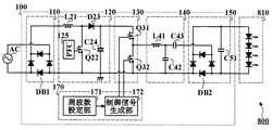
図1は、この実施の形態における照明器具800の回路構成を示す電気回路図である。
照明器具800は、商用電源などの交流電源ACから供給された電力により、LED(発光ダイオード)を点灯する。照明器具800は、点灯回路100、負荷回路810を有する。
点灯回路100は、負荷回路810に印加する直流負荷電圧を生成する。点灯回路100は、整流回路110、直流電源回路120、インバータ回路130、共振回路140、整流回路150、インバータ制御回路170を有する。
負荷回路810は、例えば直列に電気接続した複数のLEDを有する。負荷回路810は、点灯回路100が生成した直流負荷電圧により、LEDを点灯する。
FIG. 1 is an electric circuit diagram showing a circuit configuration of a
The
The
The
整流回路110は、例えば整流素子をブリッジ接続したダイオードブリッジDB1を有する。整流回路110は、交流電源ACから入力した交流電圧を全波整流して脈流電圧を生成する。
直流電源回路120(アクティブフィルタ回路)は、例えばチョークコイルL21、スイッチング素子Q22、整流素子D23、平滑コンデンサC24、PFC125からなる昇圧チョッパ回路であり、整流回路110が生成した脈流電圧から、所定の目標電圧値V0(例えば415V)の直流電圧(以下「直流電源電圧」と呼ぶ。)を生成する。
インバータ回路130は、例えば直列に電気接続した2つのスイッチング素子Q31,Q32を有する。インバータ回路130は、インバータ制御信号を入力し、入力したインバータ制御信号にしたがって、2つのスイッチング素子Q31,Q32を交互にオンオフすることにより、直流電源回路120が生成した直流電源電圧から、矩形波電圧を生成する。
共振回路140は、例えばチョークコイルL41(インダクタ)、共振コンデンサC42、結合コンデンサC43を有する。共振回路140は、チョークコイルL41と共振コンデンサC42との共振により、インバータ回路130が生成した矩形波電圧から、交流電圧を生成する。
整流回路150は、例えばダイオードブリッジDB2、平滑コンデンサC51を有する。整流回路150は、共振回路140が生成した交流電圧から直流電圧(直流負荷電圧)を生成する。
The rectifier circuit 110 includes, for example, a diode bridge DB1 in which rectifier elements are bridge-connected. The rectifier circuit 110 generates a pulsating voltage by full-wave rectifying the AC voltage input from the AC power supply AC.
The DC power supply circuit 120 (active filter circuit) is a step-up chopper circuit including, for example, a choke coil L21, a switching element Q22, a rectifying element D23, a smoothing capacitor C24, and a
The
The resonance circuit 140 includes, for example, a choke coil L41 (inductor), a resonance capacitor C42, and a coupling capacitor C43. The resonance circuit 140 generates an AC voltage from the rectangular wave voltage generated by the
The
インバータ制御回路170は、インバータ回路130を制御するインバータ制御信号を生成する。インバータ制御回路170は、周波数設定部171、制御信号生成部172を有する。
周波数設定部171は、インバータ制御信号の周波数fを設定する。インバータ回路130は、インバータ制御信号にしたがって2つのスイッチング素子Q31,Q32をオンオフするので、インバータ制御信号の周波数fは、すなわち、インバータ回路130が生成する矩形波電圧の周波数である。
制御信号生成部172は、周波数設定部171が設定した周波数fにしたがって、インバータ制御信号を生成する。
インバータ制御回路170は、例えばマイコンにより構成する。マイコンは、プログラムやデータを記憶するROMなどの不揮発性メモリや一時的にデータを記憶するRAMなどの揮発性メモリなどの記憶装置と、プログラムを実行してデータを処理する処理装置とを有する。上述した周波数設定部171や制御信号生成部172は、マイコンの処理装置がプログラムを実行することにより実現される。
なお、インバータ制御回路170は、マイコンではなく、論理回路やアナログ回路などにより構成してもよい。
The
The
The control
The
Note that the
図2は、この実施の形態における点灯処理S510の流れを示すフローチャート図である。
点灯処理S510は、LEDが消灯状態にあり、LEDの点灯を開始して、点灯状態にする点灯開始期間に実行する処理である。点灯処理S510は、起動周波数設定工程S511、タイマー初期化工程S513、経過時間判定工程S514、点灯周波数設定工程S515を有する。
FIG. 2 is a flowchart showing the flow of the lighting process S510 in this embodiment.
The lighting process S510 is a process executed during a lighting start period in which the LED is in an extinguished state and the LED is started to be lit to be in the lit state. The lighting process S510 includes a startup frequency setting step S511, a timer initialization step S513, an elapsed time determination step S514, and a lighting frequency setting step S515.
起動周波数設定工程S511において、周波数設定部171は、インバータ制御信号の周波数fを起動周波数f1に設定する。制御信号生成部172は、周波数設定部171が設定した周波数にしたがって、周波数fが起動周波数f1であるインバータ制御信号を生成する。これにより、インバータ回路130は、周波数fが起動周波数f1である矩形波電圧を生成する。
In starting frequency setting step S511, the
タイマー初期化工程S513において、周波数設定部171は、経過時間を監視するため、タイマーを初期化する。
経過時間判定工程S514において、周波数設定部171は、タイマー初期化工程S513でタイマーを初期化してからの経過時間tと所定の時間T1とを比較する。経過時間tが時間T1未満である場合、周波数設定部171は、経過時間判定工程S514を繰り返す。経過時間tが時間T1以上である場合、周波数設定部171は、点灯周波数設定工程S515へ進む。
In the timer initialization step S513, the
In the elapsed time judging step S514, the
例えば、タイマー初期化工程S513において、周波数設定部171は、タイマーとして用いるレジスタに所定の整数を記憶する。経過時間判定工程S514において、周波数設定部171は、タイマーとして用いるレジスタの値を1つ減らす。レジスタの値が0より大きい場合、周波数設定部171は、経過時間判定工程S514を繰り返し、レジスタの値が0になった場合、周波数設定部171は、点灯周波数設定工程S515へ進む。
For example, in the timer initialization step S513, the
点灯周波数設定工程S515において、周波数設定部171は、インバータ制御信号の周波数fを点灯周波数f2に設定する。制御信号生成部172は、周波数設定部171が設定した周波数にしたがって、周波数fが点灯周波数f2であるインバータ制御信号を生成する。これにより、インバータ回路130は、周波数fが点灯周波数f2である矩形波電圧を生成する。
In the lighting frequency setting step S515, the
ここで、起動周波数f1は、共振回路140のチョークコイルL41と共振コンデンサC42とにより定まる共振周波数f0より高い周波数である。チョークコイルL41のインダクタンスをL、共振コンデンサC42の静電容量をCとすると、共振周波数f0は、次の式により定まる。
また、点灯周波数f2は、起動周波数f1よりも低い周波数であり、起動周波数f1よりも共振周波数f0に近い周波数である。なお、点灯周波数f2は、共振周波数f0より高い周波数でもよいし、共振周波数f0より低い周波数でもよい。例えば、共振周波数f0が58kHz、起動周波数f1が90kHz、点灯周波数f2が45kHzであれば、起動周波数f1と共振周波数f0との差|f1−f0|が32kHzであるのに対し、点灯周波数f2と共振周波数f0との差|f2−f0|は13kHzであるから、点灯周波数f2は、起動周波数f1よりも共振周波数f0に近い。 The lighting frequency f 2 is a frequency lower than the starting frequency f 1, than starting frequency f 1 is a frequency close to the resonance frequency f 0. Incidentally, the lighting frequency f 2 may be at a frequency higher than the resonance frequency f 0, may be at a frequency lower than the resonance frequency f 0. For example, if the resonance frequency f 0 is 58 kHz, the startup frequency f 1 is 90 kHz, and the lighting frequency f 2 is 45 kHz, the difference | f 1 −f 0 | between the startup frequency f 1 and the resonance frequency f 0 is 32 kHz. On the other hand, since the difference | f 2 −f 0 | between the lighting frequency f 2 and the resonance frequency f 0 is 13 kHz, the lighting frequency f 2 is closer to the resonance frequency f 0 than the starting frequency f 1 .
負荷回路810を構成する直列に電気接続されたLEDの順方向降下電圧の合計(例えば170V)をVf(以下「点灯電圧」と呼ぶ。)とすると、整流回路150が生成する直流負荷電圧の電圧値vDが点灯電圧Vf以上であればLEDが点灯し、電圧値vDが点灯電圧Vf未満であればLEDは点灯しない。
整流回路150が生成する直流負荷電圧の電圧値vDは、共振回路140が生成する交流電圧の最大値(0−ピーク値)とほぼ等しい。共振回路140が生成する交流電圧の最大値は、共振コンデンサC42の両端に発生する電圧のピークピーク値の約半分である。
直流電源回路120が生成する直流電源電圧の電圧値が一定の場合、共振コンデンサC42の両端電圧のピークピーク値は、インバータ回路130が生成する矩形波電圧の周波数fに依存する。LEDが点灯していない状態において、共振コンデンサC42の両端電圧のピークピーク値は、周波数fが共振周波数f0に近いほど大きくなる。
When the total forward voltage drop (for example, 170 V) of the LEDs electrically connected in series constituting the
Voltage value v D of the DC load voltage of the
When the voltage value of the DC power supply voltage generated by the DC
そこで、起動周波数f1は、直流電源回路120が生成する直流電源電圧の電圧値が目標電圧値V0である場合に整流回路150が生成する直流負荷電圧の電圧値vDが点灯電圧Vf未満になる周波数に設定する。したがって、LEDは点灯しない。特に、10〜20%程度のマージンを見て、直流負荷電圧の電圧値vDが点灯電圧Vfの80〜90%未満になる周波数に設定することが望ましい。なぜなら、電源投入直後は、直流電源回路120が生成する直流電源電圧の電圧値が安定せず、オーバーシュートを起こす場合があるからである。直流電源電圧の電圧値が目標電圧値V0である場合に、直流負荷電圧の電圧値vDが点灯電圧Vfの80〜90%未満になるように設定しておけば、一時的なオーバーシュートにより、直流電源電圧の電圧値が目標電圧値V0の10〜20%増しになった場合でも、直流負荷電圧の電圧値vDが点灯電圧Vfを下回る。
Therefore, starting frequency f 1 includes a DC
これに対し、点灯周波数f2は、直流電源回路120が生成する直流電源電圧の電圧値が目標電圧値V0である場合に整流回路150が生成する直流負荷電圧の電圧値vDが点灯電圧Vf未満になる周波数に設定する。これにより、LEDが点灯する。
On the other hand, the lighting frequency f 2 is determined by the voltage value v D of the DC load voltage generated by the
インバータ回路130が生成する矩形波電圧の周波数fを起動周波数f1から点灯周波数f2に切り替えるまでの待ち時間T1は、電源投入から、直流電源回路120が生成する直流電源電圧の電圧値が目標電圧値V0で安定するまでにかかる時間よりも長い時間に設定する。これにより、直流電源電圧が安定してからLEDが点灯するので、直流電源回路120のオーバーシュートにより一時的にLEDが通常より明るくなる現象(フラッシュ現象)を防ぐことができる。
Waiting time T 1 of the frequency f of the rectangular wave voltage from the starting frequency f 1 to switch the lighting frequency f 2 to the
図3は、この実施の形態における消灯処理S520の流れを示すフローチャート図である。
消灯処理S520は、LEDが点灯状態にあり、LEDの点灯を終了して、消灯状態にする点灯終了期間に実行する処理である。消灯処理S520は、消灯周波数設定工程S521、タイマー初期化工程S523、経過時間判定工程S524、電源回路オフ工程S525を有する。
FIG. 3 is a flowchart showing the flow of the extinguishing process S520 in this embodiment.
The extinguishing process S520 is a process executed during a lighting end period in which the LED is in a lighting state, the LED is turned off, and the LED is turned off. The extinguishing process S520 includes an extinguishing frequency setting step S521, a timer initialization step S523, an elapsed time determination step S524, and a power supply circuit off step S525.
消灯周波数設定工程S521において、周波数設定部171は、インバータ制御信号の周波数fを消灯周波数f3に設定する。制御信号生成部172は、周波数設定部171が設定した周波数にしたがって、周波数fが消灯周波数f3であるインバータ制御信号を生成する。これにより、インバータ回路130は、周波数fが消灯周波数f3である矩形波電圧を生成する。
In off frequency setting step S521, the
タイマー初期化工程S523において、周波数設定部171は、経過時間を監視するため、タイマーを初期化する。
経過時間判定工程S524において、周波数設定部171は、タイマー初期化工程S523でタイマーを初期化してからの経過時間tと所定の時間T2とを比較する。経過時間tが時間T2未満である場合、周波数設定部171は、経過時間判定工程S524を繰り返す。経過時間tが時間T2以上である場合、周波数設定部171は、電源回路オフ工程S525へ進む。
In the timer initialization step S523, the
In the elapsed time judging step S524, the
電源回路オフ工程S525において、直流電源回路120は、直流電源電圧の生成を停止する。
In the power supply circuit off step S525, the DC
消灯周波数f3は、起動周波数f1と同様、直流電源回路120が生成する直流電源電圧の電圧値が目標電圧値V0である場合に整流回路150が生成する直流負荷電圧の電圧値vDが点灯電圧Vf未満になる周波数に設定する。消灯周波数f3は、起動周波数f1と同じ周波数でもよいし、異なる周波数でもよい。これにより、LEDが消灯する。
また、インバータ回路130が生成する矩形波電圧の周波数fを点灯周波数f2から消灯周波数f3に切り替えてから、直流電源回路120をオフするまでの待ち時間T2は、LEDが確実に消灯するまでの時間より長い時間に設定する。これにより、直流電源回路120をオフにした直後、一時的に直流電源電圧が不安定になった場合でも、LEDが消灯しているので、フラッシュ現象などの異常現象を防ぐことができる。
The turn-off frequency f 3 is the voltage value v D of the DC load voltage generated by the
Further, after switching the frequency f of the rectangular wave
図4は、この実施の形態における照明器具800の各部の電圧などを示すグラフ図である。
横軸は、時刻を示す。縦軸は、電圧、周波数、電流などを示す。実線701は、直流電源回路120が生成する直流電源電圧の電圧値を示す。実線702は、インバータ回路130が生成する矩形波電圧の周波数fを示す。実線703は、整流回路150が生成する直流負荷電圧の電圧値を示す。実線704は、負荷回路810を流れる電流の平均値を示す。
FIG. 4 is a graph showing the voltage of each part of the
The horizontal axis indicates time. The vertical axis represents voltage, frequency, current, and the like. A
時刻t1において、電源の投入などにより、点灯回路100が点灯処理S510を開始する。直流電源回路120が生成する直流電源電圧の電圧値は、オーバーシュートやアンダーシュートを繰り返しつつ、時刻t2までには安定して、目標電圧値V0に収束する。
At time t 1, and the like turning on the power, the
時刻t1から時刻t2までの期間は、点灯開始期間721である。
点灯開始期間721において、インバータ制御回路170は、インバータ制御信号の周波数fを起動周波数f1とし、インバータ回路130は、周波数fが起動周波数f1の矩形波電圧を生成する。
これにより、整流回路150が生成する直流負荷電圧の電圧値は、直流電源電圧の電圧値にかかわらず、点灯電圧Vfを下回る。したがって、負荷回路810には電流が流れず、LEDは点灯しない。
A period from time t 1 to time t 2 is a
In the
Thereby, the voltage value of the DC load voltage generated by the
時刻t2以降の期間は、継続点灯期間722である。
時刻t2において、インバータ制御回路170は、インバータ制御信号の周波数fを点灯周波数f2とし、インバータ回路130は、周波数fが点灯周波数f2の矩形波電圧を生成する。
これにより、時刻t3には、整流回路150が生成する直流負荷電圧の電圧値が点灯電圧Vfに達し、時刻t4には、負荷回路810を流れる電流の電流値が所望の電流値IDに達する。これにより、LEDが所望の明るさで安定して点灯する。
A period after time t 2 is a
In time t 2, the
Thereby, at time t 3 , the voltage value of the DC load voltage generated by the
時刻t5において、スイッチの操作などにより、点灯回路100が消灯処理S520を開始する。時刻t5以降の期間は、点灯終了期間723である。インバータ制御回路170は、インバータ制御信号の周波数fを消灯周波数f3とする。なお、この例において、消灯周波数f3は、起動周波数f1と同じである。インバータ回路130は、周波数fが消灯周波数f3の矩形波電圧を生成する。
これにより、時刻t6には、整流回路150が生成する直流負荷電圧の電圧値が点灯電圧Vfを下回り、負荷回路810を流れる電流が0になり、LEDが消灯する。
At time t 5, due to a switch of the operation, the
Thus, at time t 6, the voltage value of the DC load
時刻t7において、直流電源回路120が動作を停止する。直流電源回路120は生成する直流電源電圧の電圧値は、時刻t8までには0になる。
At time t 7, the DC
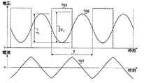
図5は、この実施の形態における照明器具800の各部の電圧などを示すグラフ図である。
横軸は、図4よりも短い時間スケールの時刻を示す。縦軸は、電圧、電流などを示す。破線705は、インバータ回路130が生成する矩形波電圧の電圧値を示す。実線706は、共振コンデンサC42の両端に発生する電圧を示す。実線707は、チョークコイルL41を流れる電流を示す。
FIG. 5 is a graph showing the voltage of each part of the
The horizontal axis indicates time on a time scale shorter than that in FIG. The vertical axis represents voltage, current, and the like. A
インバータ回路130が生成する矩形波電圧の周波数fが起動周波数f1である場合、矩形波電圧の周期Tは、起動周波数f1の逆数である。例えば、起動周波数f1が90kHzであれば、周期Tは、約11マイクロ秒である。
このとき、共振コンデンサC42の両端に発生する電圧のピークピーク値vCは、点灯電圧Vfの2倍を下回るので、負荷回路810のLEDは点灯しない。
When the frequency f of the rectangular wave voltage generated by the
At this time, the peak-to-peak value v C of the voltage generated at both ends of the resonance capacitor C42 is less than twice the lighting voltage V f , so the LED of the
図6は、この実施の形態における照明器具800の各部の電圧などを示すグラフ図である。
横軸は、図5と同じ時間スケールの時刻を示す。縦軸は、電圧、電流などを示す。図5と共通する部分には、同一の符号を付す。破線708は、負荷回路810を流れる電流を示す。
FIG. 6 is a graph showing the voltage of each part of the
The horizontal axis indicates the time on the same time scale as in FIG. The vertical axis represents voltage, current, and the like. Portions common to FIG. 5 are denoted by the same reference numerals. A
インバータ回路130が生成する矩形波電圧の周波数fが点灯周波数f2である場合、矩形波電圧の周期Tは、点灯周波数f2の逆数である。例えば、点灯周波数f2が45kHzであれば、周期Tは、約22マイクロ秒である。
このとき、共振コンデンサC42の両端に発生する電圧のピークピーク値vCは、点灯電圧Vfの2倍を上回り、負荷回路810に電流が流れて、LEDが点灯する。
If the frequency f of the rectangular wave
At this time, the peak-to-peak value v C of the voltage generated at both ends of the resonance capacitor C42 exceeds twice the lighting voltage V f , a current flows through the
ここで、点灯回路100の回路動作は、3つの期間731,732,733に分けられ、これを、インバータ回路130が生成する矩形波電圧の半周期ごとに繰り返す。期間731は、インバータ回路130が生成する矩形波電圧の瞬時値が切り替わってから、チョークコイルL41を流れる電流の極性が切り替わるまでの期間である。チョークコイルL41を流れる電流の極性が切り替わったことにより、それまでオンだったダイオードブリッジDB2の整流素子がオフになる。期間732は、その後、ダイオードブリッジDB2の逆極性の整流素子がオンになるまでの期間である。期間733は、その後、インバータ回路130が生成する矩形波電圧の瞬時値が切り替わるまでの期間である。
期間731,733において、チョークコイルL41を流れる電流のほとんどは、負荷回路810を流れ、あるいは、平滑コンデンサC51を充電することにより、間接的に負荷回路810を流れる。これに対し、期間732において、チョークコイルL41を流れる電流は、共振コンデンサC42を充電あるいは放電し、半周期後の期間732に、チョークコイルL41を通って、インバータ回路130に戻っていく。すなわち、期間732にチョークコイルL41を流れる電流は、LEDの点灯に寄与しない。
チョークコイルL41の銅損やスイッチング素子Q31,Q32のスイッチングなどによる電力損失があることを考えると、LEDの点灯に寄与しない電流は、なるべく少ないほうがよい。したがって、期間732は、できるだけ短いほうがよく、周期Tに対する期間732の比率が9分の1(角度にして40度)以下であることが望ましい。
Here, the circuit operation of the
During the
Considering that there is a power loss due to the copper loss of the choke coil L41 and the switching of the switching elements Q31 and Q32, the current that does not contribute to the lighting of the LED should be as small as possible. Therefore, the
図7は、この実施の形態におけるインバータ回路130が生成する矩形波電圧の周波数fと、共振コンデンサC42の両端に発生する電圧のピークピーク値vCとの関係を示す特性グラフ図である。
横軸は、インバータ回路130が生成する矩形波電圧の周波数fを示す。縦軸は、共振コンデンサC42の両端に発生する電圧のピークピーク値vCを示す。実線712は負荷回路810がある場合、点線713は負荷回路810がない場合を示す。閾値周波数fTは、共振コンデンサC42の両端に発生する電圧のピークピーク値vCが点灯電圧Vfの2倍と等しくなる周波数を表わす。
FIG. 7 is a characteristic graph showing the relationship between the frequency f of the rectangular wave voltage generated by the
The horizontal axis represents the frequency f of the rectangular wave voltage generated by the
インバータ回路130が生成する矩形波電圧の周波数fが閾値周波数fTより高く、共振コンデンサC42の両端に発生する電圧のピークピーク値vCが点灯電圧Vfの2倍を下回る場合は、負荷回路810があってもなくても同じであり、ピークピーク値vCは、チョークコイルL41と共振コンデンサC42との共振周波数f0をピークとする山型を描く。
Higher than the frequency f is the threshold frequency f T of the rectangular wave
インバータ回路130が生成する矩形波電圧の周波数fが閾値周波数fTより低く、共振コンデンサC42の両端に発生する電圧のピークピーク値vCが点灯電圧Vfの2倍を上回る場合、負荷回路810を電流が流れるので、共振周波数f0’は、並列に電気接続した共振コンデンサC42と結合コンデンサC43との合成による等価コンデンサと、チョークコイルL41とによって定まる。並列に電気接続したコンデンサの合成静電容量は各コンデンサの静電容量の和であるから、等価コンデンサの静電容量は共振コンデンサC42の静電容量より大きくなり、共振周波数f0’は、共振周波数f0より低くなる。
Frequency f of the rectangular wave
図8は、この実施の形態におけるインバータ回路130が生成する矩形波電圧の周波数fと、負荷回路810を流れる電流との関係を示す特性グラフ図である。
横軸は、インバータ回路130が生成する矩形波電圧の周波数fを示す。縦軸は、負荷回路810を流れる電流の平均値を示す。実線714は、周波数fとLEDを流れる電流の平均値との関係を示す。
FIG. 8 is a characteristic graph showing the relationship between the frequency f of the rectangular wave voltage generated by the
The horizontal axis represents the frequency f of the rectangular wave voltage generated by the
インバータ回路130が生成する矩形波電圧の周波数fが閾値周波数fTより高い場合、負荷回路810を流れる電流は、0である。
インバータ回路130が生成する矩形波電圧の周波数fが閾値周波数fTより低い場合、負荷回路810を流れる電流の平均値は、共振周波数f0’をピークとする山型を描く。
したがって、負荷回路810を流れる電流の平均値が所望の電流値IDになるよう、点灯周波数f2を設定することにより、LEDを所望の明るさで点灯することができる。
If the frequency f of the rectangular wave
If the frequency f of the rectangular wave
Therefore, by setting the lighting frequency f 2 so that the average value of the current flowing through the
なお、利用者の操作により、点灯周波数f2を変えられるよう構成してもよい。これにより、LEDの明るさを調整することができるので、照明器具800に調光機能を持たせることができる。
Incidentally, the operation of the user, may be configured to be changed the lighting frequency f 2. Thereby, since the brightness of LED can be adjusted, the
図9は、この実施の形態における共振回路140のパラメータと点灯周波数f2との関係を示すグラフ図である。
横軸は、共振コンデンサC42の静電容量を示す。縦軸は、点灯周波数f2を示す。実線741〜743は、チョークコイルL41のインダクタンス及び共振コンデンサC42の静電容量を変えた場合に、負荷回路810を流れる電流が所定の電流値となる点灯周波数f2を示し、実線741はチョークコイルL41のインダクタンスが小さい場合、実線742はチョークコイルL41のインダクタンスが中間の場合、実線743はチョークコイルL41のインダクタンスが大きい場合を示す。
FIG. 9 is a graph showing the relationship between the parameters of the resonance circuit 140 and the lighting frequency f 2 in this embodiment.
The horizontal axis shows the capacitance of the resonant capacitor C42. The vertical axis shows the operating frequency f 2. The solid line 741-743, when changing the inductance and capacitance of the resonant capacitor C42 of the choke coil L41, shows the operating frequency f 2 at which the current flowing through the
チョークコイルL41のインダクタンスが大きいほど、チョークコイルL41を流れる電流が制限される。このため、負荷回路810を流れる電流を所定の電流値に保つためには、点灯周波数f2を小さくする必要がある。
The larger the inductance of the choke coil L41, the more the current flowing through the choke coil L41 is limited. Therefore, in order to keep the current flowing through the
図10は、この実施の形態における共振回路140のパラメータと期間732の比率との関係を示すグラフ図である。
横軸は、共振コンデンサC42の静電容量を示す。縦軸は、周期Tに対する期間732の比率を示す。実線751〜753は、チョークコイルL41のインダクタンス及び共振コンデンサC42の静電容量を変えた場合における期間732の角度を示し、実線751はチョークコイルL41のインダクタンスが小さい場合、実線752はチョークコイルL41のインダクタンスが中間の場合、実線753はチョークコイルL41のインダクタンスが大きい場合を示す。
FIG. 10 is a graph showing the relationship between the parameters of the resonance circuit 140 and the ratio of the
The horizontal axis shows the capacitance of the resonant capacitor C42. The vertical axis represents the ratio of the
このように、チョークコイルL41のインダクタンスが大きいほど、期間732の比率は小さくなる。これは、チョークコイルL41のインダクタンスが大きいほど点灯周波数f2が低くなるので、周期Tが長くなるからである。
また、共振コンデンサC42の静電容量が小さいほど、期間732の比率は小さくなる。これは、共振コンデンサC42の静電容量が小さいほど、共振コンデンサC42を充放電するのにかかる時間が短くなるからである。
Thus, the ratio of the
Further, the smaller the capacitance of the resonant capacitor C42, the smaller the ratio of the
上述したように、期間732の比率は9分の1以下であることが望ましいので、期間732の比率が9分の1以下となるよう、チョークコイルL41のインダクタンス及び共振コンデンサC42の静電容量を設定する。
これにより、チョークコイルL41の銅損やスイッチング素子Q31,Q32のスイッチングなどによる電力損失を小さくすることができ、点灯回路100の電力効率を高めることができる。
As described above, since the ratio of the
Thereby, the power loss due to the copper loss of the choke coil L41 and the switching of the switching elements Q31 and Q32 can be reduced, and the power efficiency of the
実施の形態2.
実施の形態2について、図11〜図13を用いて説明する。
なお、実施の形態1で説明した照明器具800と共通する部分については、同一の符号を付し、説明を省略する。
Embodiment 2. FIG.
The second embodiment will be described with reference to FIGS.
In addition, about the part which is common in the
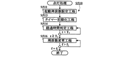
図11は、この実施の形態における点灯処理S510の流れを示すフローチャート図である。
点灯処理S510は、起動周波数設定工程S511、タイマー初期化工程S513、経過時間判定工程S514、周波数変更工程S516を有する。
FIG. 11 is a flowchart showing the flow of the lighting process S510 in this embodiment.
The lighting process S510 includes a startup frequency setting step S511, a timer initialization step S513, an elapsed time determination step S514, and a frequency change step S516.
周波数変更工程S516において、周波数設定部171は、設定したインバータ制御信号の周波数fを変更して、変更前よりも点灯周波数f2に近づける。制御信号生成部172は、周波数設定部171が変更した周波数にしたがって、インバータ制御信号を生成する。これにより、インバータ回路130は、周波数設定部171が変更した変更後の周波数の矩形波電圧を生成する。
変更後の周波数fが点灯周波数f2より高い場合、周波数設定部171は、周波数変更工程S516を繰り返す。
変更後の周波数fが点灯周波数f2と等しい場合、周波数設定部171は、点灯処理S510を終了する。
In the frequency changing step S516, the
If the frequency f after the change is higher than the operating frequency f 2, the
If the frequency f after the change is equal to the operating frequency f 2, the
例えば、起動周波数f1と点灯周波数f2との差f1−f2の100分の1をステップ周波数Δfとし、周波数変更工程S516において、周波数設定部171は、インバータ制御信号の周波数fをステップ周波数だけ低い周波数f−Δfに変更する。例えば、起動周波数f1が90kHz、点灯周波数が45kHzであれば、ステップ周波数Δfは、450Hzである。周波数設定部171は、これを100回繰り返す。これにより、インバータ制御信号の周波数は、起動周波数f1である90kHzから、89.55kHz、89.1kHz、88.65kHzと徐々に低くなり、点灯周波数f2である45kHzに達する。
For example, 1/100 of the difference f 1 −f 2 between the starting frequency f 1 and the lighting frequency f 2 is set as the step frequency Δf, and in the frequency changing step S 516, the
図12は、この実施の形態における消灯処理S520の流れを示すフローチャート図である。
消灯処理S520は、周波数変更工程S522、電源回路オフ工程S525を有する。
FIG. 12 is a flowchart showing the flow of the extinguishing process S520 in this embodiment.
The extinguishing process S520 includes a frequency changing step S522 and a power supply circuit off step S525.
周波数変更工程S522において、周波数設定部171は、設定したインバータ制御信号の周波数fを変更して、変更前よりも消灯周波数f3に近づける。制御信号生成部172は、周波数設定部171が変更した周波数にしたがって、インバータ制御信号を生成する。これにより、インバータ回路130は、周波数設定部171が変更した変更後の周波数の矩形波電圧を生成する。
変更後の周波数fが消灯周波数f3より低い場合、周波数設定部171は、周波数変更工程S522を繰り返す。
変更後の周波数fが点灯周波数f2と等しい場合、周波数設定部171は、電源回路オフ工程S525へ進む。
In the frequency changing step S522, the
If the frequency f after the change is lower than the off frequency f 3, the
If the frequency f after the change is equal to the operating frequency f 2, the
このように、点灯回路100は、点灯処理S510や消灯処理S520において、インバータ回路130が生成する矩形波電圧の周波数fを連続的に少しずつ変化させる。
Thus, the
図13は、この実施の形態における照明器具800の各部の電圧などを示すグラフ図である。
FIG. 13 is a graph showing the voltage of each part of the
点灯開始期間721は、時刻t1から時刻t4までの期間である。
時刻t2において、周波数設定部171は、インバータ制御信号の周波数fの変更を開始し、インバータ回路130が生成する矩形波電圧の周波数fは、少しずつ低くなる。これに伴って、整流回路150が生成する直流負荷電圧の電圧値は、少しずつ高くなる。
時刻t3において、インバータ回路130が生成する矩形波電圧の周波数fが閾値周波数fTに達すると、整流回路150が生成する直流負荷電圧の電圧値は、点灯電圧Vfに達し、負荷回路810に電流が流れ始める。
その後、インバータ回路130が生成する矩形波電圧の周波数fが低くなるにつれて、負荷回路810を流れる電流が徐々に大きくなる。
時刻t4において、インバータ回路130が生成する矩形波電圧の周波数fが点灯周波数f2に達すると、負荷回路810を流れる電流の電流値が、所望の電流値IDになる。
In time t 2, the
At time t 3, when the frequency f of the rectangular wave
Thereafter, as the frequency f of the rectangular wave voltage generated by the
At time t 4, when the frequency f of the rectangular wave
点灯終了期間723は、時刻t5から時刻t8までの期間である。
時刻t5において、周波数設定部171は、インバータ制御信号の周波数fの変更を開始し、インバータ回路130が生成する矩形波電圧の周波数fは、少しずつ高くなる。これに伴って、負荷回路810を流れる電流は、少しずつ小さくなる。
時刻t6において、インバータ回路130が生成する矩形波電圧の周波数fが閾値周波数fTに達すると、整流回路150が生成する直流負荷電圧の電圧値は、点灯電圧Vfまで下がる。
その後、インバータ回路130が生成する矩形波電圧の周波数fが更に高くなると、整流回路150が生成する直流負荷電圧の電圧値が点灯電圧Vfを下回るので、負荷回路810を流れる電流は0になる。
時刻t7において、インバータ回路130が生成する矩形波電圧の周波数fは、消灯周波数f3(=f1)に達する。直流電源回路120は、直流電源電圧の生成を停止する。
Lighting end of the
At time t 5, the
At time t 6, when the frequency f of the rectangular wave
Thereafter, when the frequency f of the rectangular wave voltage generated by the
At time t 7 , the frequency f of the rectangular wave voltage generated by the
このように、インバータ回路130が生成する矩形波電圧の周波数fを徐々に変化させることにより、周波数fを急激に変化させたときに発生する可能性がある過渡現象を抑えることができる。また、点灯時には、LEDが徐々に明るくなって所望の明るさに達するフェードインの照明効果を得ることができ、消灯時には、逆に、LEDが徐々に暗くなって消灯するフェードアウトの照明効果を得ることができる。
As described above, by gradually changing the frequency f of the rectangular wave voltage generated by the
実施の形態3.
実施の形態3について、図14を用いて説明する。
なお、実施の形態1または実施の形態2で説明した照明器具800と共通する部分については、同一の符号を付し、説明を省略する。
In addition, about the part which is common in the
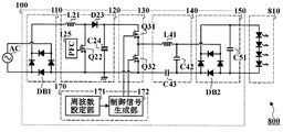
図14は、この実施の形態における照明器具800の回路構成を示す電気回路図である。
この実施の形態における照明器具800は、共振回路140の構成が実施の形態1と異なり、結合コンデンサC43が、共振コンデンサC42に対して並列ではなく、直列に電気接続している。
FIG. 14 is an electric circuit diagram showing a circuit configuration of the
In the
結合コンデンサC43の静電容量は、共振コンデンサC42の静電容量と比較して十分大きいものとする。
LEDが点灯していない状態では、直列に接続した共振コンデンサC42と結合コンデンサC43との合成による等価コンデンサを考えればよい。等価コンデンサの静電容量の逆数は、直列に接続した各コンデンサの静電容量の逆数の和であるから、結合コンデンサC43の静電容量が共振コンデンサC42の静電容量と比較して十分大きければ、等価コンデンサの静電容量は、共振コンデンサC42の静電容量とほぼ等しい。
また、LEDが点灯している状態では、共振コンデンサC42の両端電圧が負荷回路810の点灯電圧Vfによってほぼ一定に保たれるので、共振周波数f0’は、チョークコイルL41のインダクタンスと、結合コンデンサC43の静電容量とによって定まる。
したがって、点灯回路100は、実施の形態1における点灯回路100と同様に動作する。
It is assumed that the capacitance of the coupling capacitor C43 is sufficiently larger than the capacitance of the resonance capacitor C42.
In a state where the LED is not lit, an equivalent capacitor by combining a resonance capacitor C42 and a coupling capacitor C43 connected in series may be considered. Since the reciprocal of the capacitance of the equivalent capacitor is the sum of the reciprocals of the capacitances of the capacitors connected in series, if the capacitance of the coupling capacitor C43 is sufficiently larger than the capacitance of the resonance capacitor C42. The capacitance of the equivalent capacitor is substantially equal to the capacitance of the resonance capacitor C42.
In a state where the LED is lit, the voltage across the resonant capacitor C42 is kept substantially constant by the lighting voltage V f of the
Therefore,
このように、共振回路140の構成を変えても、実施の形態1や実施の形態2で説明した効果と同様の効果を得ることができる。 Thus, even if the configuration of the resonance circuit 140 is changed, the same effects as those described in the first embodiment and the second embodiment can be obtained.
また、整流回路110、直流電源回路120などの構成についても、ここまでで説明した構成は一例であり、他の構成に代えてもよいことは明らかである。
In addition, regarding the configuration of the rectifier circuit 110, the DC
100 点灯回路、110,150 整流回路、120 直流電源回路、125 PFC、130 インバータ回路、140 共振回路、170 インバータ制御回路、171 周波数設定部、172 制御信号生成部、721 点灯開始期間、722 継続点灯期間、723 点灯終了期間、731〜733 期間、800 照明器具、810 負荷回路、AC 交流電源、C24,C51 平滑コンデンサ、C42 共振コンデンサ、C43 結合コンデンサ、D23 整流素子、DB1,DB2 ダイオードブリッジ、L21,L41 チョークコイル、Q22,Q31,Q32 スイッチング素子。 100 lighting circuit, 110, 150 rectifier circuit, 120 DC power supply circuit, 125 PFC, 130 inverter circuit, 140 resonance circuit, 170 inverter control circuit, 171 frequency setting unit, 172 control signal generation unit, 721 lighting start period, 722 continuous lighting Period, 723 lighting end period, 731 to 733 period, 800 lighting fixture, 810 load circuit, AC AC power supply, C24, C51 smoothing capacitor, C42 resonance capacitor, C43 coupling capacitor, D23 rectifier, DB1, DB2 diode bridge, L21, L41 Choke coil, Q22, Q31, Q32 switching element.
Claims (5)
直流電源電圧を生成する直流電源回路と、
上記直流電源回路が生成した直流電源電圧から矩形波電圧を生成するインバータ回路と、
コイルとコンデンサとを有し、上記コイルと上記コンデンサとの共振により、上記インバータ回路が生成した矩形波電圧から交流電圧を生成する共振回路と、
上記共振回路が生成した交流電圧を整流して直流負荷電圧を生成する整流回路とを有し、
上記インバータ回路は、上記発光ダイオードを消灯状態から点灯状態に切り替える点灯開始期間及び上記発光ダイオードを点灯状態から消灯状態に切り替える点灯終了期間のうち少なくともいずれかにおいて生成する矩形波電圧の周波数が、上記発光ダイオードを継続して点灯する継続点灯期間において生成する矩形波電圧の周波数よりも、上記共振回路の共振周波数から遠い周波数であって、上記負荷回路の発光ダイオードが点灯する点灯電圧より上記整流回路が生成する直流負荷電圧が低くなる周波数であることを特徴とする点灯回路。 In a lighting circuit for lighting a light emitting diode by applying a DC load voltage to a load circuit having the light emitting diode,
A DC power supply circuit for generating a DC power supply voltage;
An inverter circuit that generates a rectangular wave voltage from the DC power supply voltage generated by the DC power supply circuit;
A resonance circuit that includes a coil and a capacitor, and generates an AC voltage from a rectangular wave voltage generated by the inverter circuit by resonance between the coil and the capacitor;
A rectifier circuit that rectifies the AC voltage generated by the resonant circuit to generate a DC load voltage;
In the inverter circuit, the frequency of the rectangular wave voltage generated in at least one of a lighting start period for switching the light emitting diode from a lighting state to a lighting state and a lighting end period for switching the light emitting diode from a lighting state to a lighting state is The rectifier circuit has a frequency farther from the resonant frequency of the resonant circuit than the frequency of the rectangular wave voltage generated in the continuous lighting period in which the light emitting diode is continuously lit, and the lighting voltage at which the light emitting diode of the load circuit is lit A lighting circuit characterized by having a frequency at which the DC load voltage generated by is reduced .
Priority Applications (1)
| Application Number | Priority Date | Filing Date | Title |
|---|---|---|---|
| JP2009193979A JP5383380B2 (en) | 2009-08-25 | 2009-08-25 | Lighting circuit and lighting fixture |
Applications Claiming Priority (1)
| Application Number | Priority Date | Filing Date | Title |
|---|---|---|---|
| JP2009193979A JP5383380B2 (en) | 2009-08-25 | 2009-08-25 | Lighting circuit and lighting fixture |
Publications (3)
| Publication Number | Publication Date |
|---|---|
| JP2011048916A JP2011048916A (en) | 2011-03-10 |
| JP2011048916A5 JP2011048916A5 (en) | 2012-07-26 |
| JP5383380B2 true JP5383380B2 (en) | 2014-01-08 |
Family
ID=43835072
Family Applications (1)
| Application Number | Title | Priority Date | Filing Date |
|---|---|---|---|
| JP2009193979A Expired - Fee Related JP5383380B2 (en) | 2009-08-25 | 2009-08-25 | Lighting circuit and lighting fixture |
Country Status (1)
| Country | Link |
|---|---|
| JP (1) | JP5383380B2 (en) |
Cited By (2)
| Publication number | Priority date | Publication date | Assignee | Title |
|---|---|---|---|---|
| US9867648B2 (en) | 2014-06-04 | 2018-01-16 | Csa Medical, Inc. | Method and system for consistent, repeatable, and safe cryospray treatment of airway tissue |
| US12048469B2 (en) | 2013-03-04 | 2024-07-30 | Csa Medical, Inc. | Cryospray catheters |
Families Citing this family (1)
| Publication number | Priority date | Publication date | Assignee | Title |
|---|---|---|---|---|
| JP6414676B2 (en) * | 2014-09-10 | 2018-10-31 | パナソニックIpマネジメント株式会社 | Lighting device and lighting apparatus |
Family Cites Families (2)
| Publication number | Priority date | Publication date | Assignee | Title |
|---|---|---|---|---|
| JPH0550489U (en) * | 1991-12-11 | 1993-07-02 | 株式会社コパル | Light emitting device |
| DE602005006587D1 (en) * | 2005-11-22 | 2008-06-19 | Patent Treuhand Ges Fuer Elektrische Gluehlampen Mbh | Drive device for LED cells |
-
2009
- 2009-08-25 JP JP2009193979A patent/JP5383380B2/en not_active Expired - Fee Related
Cited By (4)
| Publication number | Priority date | Publication date | Assignee | Title |
|---|---|---|---|---|
| US12048469B2 (en) | 2013-03-04 | 2024-07-30 | Csa Medical, Inc. | Cryospray catheters |
| US9867648B2 (en) | 2014-06-04 | 2018-01-16 | Csa Medical, Inc. | Method and system for consistent, repeatable, and safe cryospray treatment of airway tissue |
| US11478290B2 (en) | 2014-06-04 | 2022-10-25 | Csa Medical, Inc. | Method and system for consistent, repeatable, and safe cryospray treatment of airway tissue |
| US11963709B2 (en) | 2014-06-04 | 2024-04-23 | Csa Medical, Inc. | Method and system for consistent, repeatable, and safe cryospray treatment of airway tissue |
Also Published As
| Publication number | Publication date |
|---|---|
| JP2011048916A (en) | 2011-03-10 |
Similar Documents
| Publication | Publication Date | Title |
|---|---|---|
| JP5027498B2 (en) | Discharge lamp lighting device and image display device | |
| JP5302755B2 (en) | Power supply | |
| JP6551735B2 (en) | Dimmable lighting circuit and lighting fixture | |
| JP2011034847A (en) | Power supply device and lighting fixture | |
| JP2009289492A (en) | High-pressure discharge lamp lighting device and luminaire | |
| JP5383380B2 (en) | Lighting circuit and lighting fixture | |
| JP5159895B2 (en) | Lighting device for in-vehicle light source | |
| JP2009289480A (en) | High-pressure discharge lamp lighting device, and luminaire | |
| JP6292503B2 (en) | Power supply device and LED lighting device | |
| JP4681437B2 (en) | Power supply | |
| JP5773786B2 (en) | Light source lighting device and lighting fixture | |
| JP5079043B2 (en) | Power supply device, discharge lamp lighting device including the power supply device, and lighting fixture including the discharge lamp lighting device | |
| JP5293961B2 (en) | LED drive circuit | |
| JP2010080138A (en) | High-pressure discharge lamp lighting device, and lighting fixture | |
| JP6648502B2 (en) | Lighting device and lighting equipment | |
| JP6328394B2 (en) | Dimming lighting device | |
| JP6417706B2 (en) | Discharge lamp lighting device and lighting device | |
| JP4127357B2 (en) | Inverter with starter circuit | |
| JP5152982B2 (en) | Discharge lamp lighting device | |
| JP6825704B2 (en) | Power converters, lighting fixtures, electrical equipment | |
| JP2009199876A (en) | Discharge lamp lighting device, and illumination fixture equipped with this discharge lamp lighting device | |
| JP6745476B2 (en) | Lighting device and lighting equipment | |
| JP2011029096A (en) | Discharge lamp lighting device and lighting apparatus | |
| JP5742530B2 (en) | High pressure discharge lamp lighting device, high pressure discharge lamp lighting method using the same, and lighting fixture | |
| JP2004241370A (en) | High-pressure discharge lamp lighting device and illumination device |
Legal Events
| Date | Code | Title | Description |
|---|---|---|---|
| A521 | Request for written amendment filed |
Free format text: JAPANESE INTERMEDIATE CODE: A523 Effective date: 20120611 |
|
| A621 | Written request for application examination |
Free format text: JAPANESE INTERMEDIATE CODE: A621 Effective date: 20120611 |
|
| RD04 | Notification of resignation of power of attorney |
Free format text: JAPANESE INTERMEDIATE CODE: A7424 Effective date: 20121207 |
|
| A977 | Report on retrieval |
Free format text: JAPANESE INTERMEDIATE CODE: A971007 Effective date: 20130730 |
|
| TRDD | Decision of grant or rejection written | ||
| A01 | Written decision to grant a patent or to grant a registration (utility model) |
Free format text: JAPANESE INTERMEDIATE CODE: A01 Effective date: 20130903 |
|
| A61 | First payment of annual fees (during grant procedure) |
Free format text: JAPANESE INTERMEDIATE CODE: A61 Effective date: 20131001 |
|
| R150 | Certificate of patent or registration of utility model |
Ref document number: 5383380 Country of ref document: JP Free format text: JAPANESE INTERMEDIATE CODE: R150 Free format text: JAPANESE INTERMEDIATE CODE: R150 |
|
| R250 | Receipt of annual fees |
Free format text: JAPANESE INTERMEDIATE CODE: R250 |
|
| R250 | Receipt of annual fees |
Free format text: JAPANESE INTERMEDIATE CODE: R250 |
|
| R250 | Receipt of annual fees |
Free format text: JAPANESE INTERMEDIATE CODE: R250 |
|
| R250 | Receipt of annual fees |
Free format text: JAPANESE INTERMEDIATE CODE: R250 |
|
| R250 | Receipt of annual fees |
Free format text: JAPANESE INTERMEDIATE CODE: R250 |
|
| LAPS | Cancellation because of no payment of annual fees |


