JP5383003B2 - Auxiliary curler for hair curlers - Google Patents

Auxiliary curler for hair curlers Download PDF

Info

Publication number
JP5383003B2
JP5383003B2 JP2007086535A JP2007086535A JP5383003B2 JP 5383003 B2 JP5383003 B2 JP 5383003B2 JP 2007086535 A JP2007086535 A JP 2007086535A JP 2007086535 A JP2007086535 A JP 2007086535A JP 5383003 B2 JP5383003 B2 JP 5383003B2
Authority
JP
Japan
Prior art keywords
hair
curler
handle
hair curler
auxiliary
Prior art date
Legal status (The legal status is an assumption and is not a legal conclusion. Google has not performed a legal analysis and makes no representation as to the accuracy of the status listed.)
Expired - Fee Related
Application number
JP2007086535A
Other languages
Japanese (ja)
Other versions
JP2008237821A (en
Inventor
晃 菅原
Current Assignee (The listed assignees may be inaccurate. Google has not performed a legal analysis and makes no representation or warranty as to the accuracy of the list.)
Kaijirushi Hamono Center KK
Original Assignee
Kaijirushi Hamono Center KK
Priority date (The priority date is an assumption and is not a legal conclusion. Google has not performed a legal analysis and makes no representation as to the accuracy of the date listed.)
Filing date
Publication date
Application filed by Kaijirushi Hamono Center KK filed Critical Kaijirushi Hamono Center KK
Priority to JP2007086535A priority Critical patent/JP5383003B2/en
Publication of JP2008237821A publication Critical patent/JP2008237821A/en
Application granted granted Critical
Publication of JP5383003B2 publication Critical patent/JP5383003B2/en
Expired - Fee Related legal-status Critical Current
Anticipated expiration legal-status Critical

Links

Images

Landscapes

  • Hair Curling (AREA)

Description

本発明は、主に一般の女性が使用するヘアカーラー用の補助カーラーに関する。   The present invention relates to an auxiliary curler for a hair curler used mainly by general women.

ハンドルを着脱自在に取り付けることができるヘアカーラーは存在する(例えば、特許文献1参照。)。
特表2000−511096号公報
There is a hair curler to which a handle can be detachably attached (see, for example, Patent Document 1).
Special Table 2000-511096

本発明は、毛髪をヘアカーラーに迅速且つ確実に巻き付けていくことができるヘアカーラー用の補助カーラーを提供することを課題とする。   This invention makes it a subject to provide the auxiliary curler for hair curlers which can wind hair around a hair curler quickly and reliably.

特許文献1のようにハンドルを着脱自在に取り付けることができるヘアカーラーは、ハンドルを握りながら毛髪をヘアカーラーに巻き付けていくので、ハンドルを有しないヘアカーラーよりも迅速に毛髪の巻き付けをすることができる。そして、毛髪の巻き付けが終了したときにハンドルをヘアカーラーから取り外してヘアカーラーのみを頭に残すことができる。   A hair curler that can be detachably attached to a handle as in Patent Document 1 winds hair around the hair curler while grasping the handle, so that the hair can be wound more quickly than a hair curler without a handle. it can. When the winding of the hair is finished, the handle can be removed from the hair curler and only the hair curler can be left on the head.

特許文献1では、ハンドルをヘアカーラーから取り外す手段はハンドル基部の外周面に設けられたボタンであり、このボタンを軸に垂直な方向に押すことによってヘアカーラーとハンドルとの係合を解除する構造である。この解除構造は解除するための力が軸に垂直な方向に加わるから、この力がヘアカーラーとハンドルとを分離する作用をなさない。係合の解除後にヘアカーラーとハンドルを分離するためには軸線方向に力を加えて分離しなければならないから、そのための作業が必要となる。したがって、ヘアカーラーとハンドルを解除する作業は、先ずボタンを押して係合を解除し、次いでヘアカーラーを一方の手で持ちながら他方の手でハンドルを掴んでヘアカーラーから引き出すという2つの操作を行わねばならない。通常ヘアカーラーは頭にいくつも付けるのであるから、一つのヘアカーラーの取り付けに2つの操作を行わなければならない引用文献1のヘアカーラーは毛髪の巻き付けについて迅速性に欠けるのである。 In Patent Document 1, the means for removing the handle from the hair curler is a button provided on the outer peripheral surface of the handle base, and the structure that releases the engagement between the hair curler and the handle by pushing the button in a direction perpendicular to the axis. It is. Since the releasing force is applied in a direction perpendicular to the axis, this releasing structure does not act to separate the hair curler from the handle. In order to separate the hair curler from the handle after the disengagement, it is necessary to apply a force in the axial direction to separate the hair curler and the handle. Therefore, the operation of releasing the hair curler and the handle is performed by two operations: first pressing the button to release the engagement, then holding the hair curler with one hand and grasping the handle with the other hand and pulling it out of the hair curler. I have to. Usually, a number of hair curlers are attached to the head, so that the hair curler of Reference 1 which requires two operations for attaching one hair curler is not quick in winding hair.

さらに、引用文献1も含めて従来のヘアカーラーは特に毛髪の長い使用者が使用するときは、巻いた毛髪の上からさらに毛髪を巻き付けるために毛髪が外れ易く、毛髪を確実に巻き付けることが困難であった。このように、引用文献1のハンドル付きヘアカーラーは毛髪の巻き付けについて迅速性に欠け、さらに巻き付けの確実性も欠いている。そこで、本発明は毛髪の巻き付けを迅速に行うことができるとともに毛髪を確実に巻き付けることができるヘアカーラー用の補助カーラーを提供することを目的とするものである。 Furthermore, the conventional hair curlers including the cited reference 1 are particularly difficult to wrap around the hair because it is easy to come off because the hair is further wound on the wound hair, especially when used by users with long hair. Met. As described above, the hair curler with the handle of the cited document 1 lacks quickness in winding the hair, and further lacks the certainty of winding. Accordingly, an object of the present invention is to provide an auxiliary curler for a hair curler that can rapidly wrap hair and can reliably wind hair.

本発明は、ヘアカーラー用の補助カーラーであって、可撓性を有し断面がC字形に形成された芯部材の表面に多数のフック状繊維である毛髪の巻き付け部が設けられ、ヘアカーラーの外周面上の一部に重ね合わせ可能の形状に形成され、且つヘアカーラーに巻き付けられた毛髪の上に重ねることができるように形成され、芯部材の外周面に多数のフック状繊維である毛髪の巻き付け部を設けた前記ヘアカーラーの外周面上に着脱自在に取り付けることができる構成である。 The present invention is an auxiliary curler for hair curlers, in which a hair wrapping portion, which is a number of hook-like fibers, is provided on the surface of a flexible core member having a C-shaped cross section. A plurality of hook-like fibers are formed on the outer peripheral surface of the core member so as to be superposed on a part of the outer peripheral surface of the core member and to be able to be superimposed on the hair wound around the hair curler. It is the structure which can be detachably attached on the outer peripheral surface of the said hair curler which provided the winding part of the hair .

本発明は、可撓性を有し断面がC字形に形成された芯部材の表面に多数のフック状繊維である毛髪の巻き付け部が設けられ、ヘアカーラーの外周面上の一部に重ね合わせ可能の形状に形成され、且つヘアカーラーに巻き付けられた毛髪の上に重ねることができるように形成され、芯部材の外周面に多数のフック状繊維である毛髪の巻き付け部を設けた前記ヘアカーラーの外周面上に着脱自在に取り付けることができる。したがって、毛髪の巻き付けがヘアカーラーの一周を超えてさらに巻き付けようとするときに、巻き付けた毛髪の上に補助カーラーを重ねるように装着すれば、補助カーラーの表面に巻き付け部が設けられているから毛髪を確実に巻き付けることができる。これにより、作業中に毛髪がほどけることがないので巻き直しがなく作業を迅速に行うことができる。 In the present invention , a hair wrapping portion, which is a large number of hook-like fibers, is provided on the surface of a flexible core member having a C-shaped cross section, and is superimposed on a part of the outer peripheral surface of the hair curler. The hair curler which is formed in a possible shape and is formed so as to be able to be superimposed on the hair wound around the hair curler, and is provided with a hair winding portion which is a large number of hook-like fibers on the outer peripheral surface of the core member Can be detachably mounted on the outer peripheral surface of the . Therefore, when the hair is to be wound more than once around the hair curler, if the auxiliary curler is mounted so as to overlap the wound hair, the winding portion is provided on the surface of the auxiliary curler. The hair can be surely wound. Thereby, since the hair does not unravel during the work, the work can be quickly performed without rewinding.

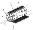
次に本発明の実施形態を説明する。図4に示すようにヘアカーラー1は芯部材2の表面に金属部材3が巻き付けられ、さらにその上に毛髪巻き付け部材4が巻き付けられて装着されている。   Next, an embodiment of the present invention will be described. As shown in FIG. 4, the hair curler 1 is mounted by winding a metal member 3 around the surface of the core member 2 and further winding a hair winding member 4 thereon.

芯部材2は、合成樹脂や薄板や耐水性紙材などの軽量の材料で円筒形に形成されている。芯部材2は中空であって、その周面部は長手方向に延びる複数の縦枠部5とその縦枠部5を横切って周方向に延びる複数の横枠部6とで仕切られた複数の通孔7が形成されている。通孔7によって通気性を良くすることができるが、通孔7がなくてもよい。芯部材2の長さは65mm〜130mm程度で、直径は25mm〜60mm程度で、特に好ましいサイズは長さが約70mmで直径が約35mmであるがこれらの数値に限定されないことは勿論である。 The core member 2 is formed in a cylindrical shape with a lightweight material such as a synthetic resin, a thin plate, or water-resistant paper. The core member 2 is hollow, and a peripheral surface portion thereof is divided by a plurality of vertical frame portions 5 extending in the longitudinal direction and a plurality of horizontal frame portions 6 extending across the vertical frame portion 5 and extending in the circumferential direction. A hole 7 is formed. Although the air permeability can be improved by the through hole 7, the through hole 7 may not be provided. The core member 2 has a length of about 65 mm to 130 mm and a diameter of about 25 mm to 60 mm. Particularly preferred sizes are about 70 mm in length and about 35 mm in diameter, but it is of course not limited to these values.

金属部材3は、芯部材2の表面に巻き付けるものであるから板状に形成されていることが好ましく、アルミニウム板やステンレス板などが用いられる。金属部材3の表面には周方向に長円形の多数の通孔8が設けられている。通孔8によって通気性を良くすることができるが、通孔8がなくてもよい。金属部材3を巻き付けることにより熱を伝えてカールすることができる。また、金属部材3の表面にセラミックをコーティングすることにより熱がさめにくくしっかりカールすることができる。   Since the metal member 3 is wound around the surface of the core member 2, it is preferably formed in a plate shape, and an aluminum plate, a stainless plate, or the like is used. A large number of oblong through holes 8 are provided in the circumferential direction on the surface of the metal member 3. Although the air permeability can be improved by the through hole 8, the through hole 8 may not be provided. By winding the metal member 3, heat can be transmitted and curled. Further, by coating the surface of the metal member 3 with ceramic, it is possible to curl firmly by preventing the heat from being suppressed.

毛髪巻き付け部材4は、生地9の表面に多数のフック状繊維10を設けたものである。フック状繊維10を設けると毛髪を容易に絡ませることができる。 The hair wrapping member 4 is provided with a number of hook-like fibers 10 on the surface of the fabric 9. When the hook-like fiber 10 is provided, the hair can be easily entangled .

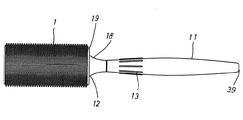
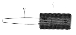
図1に示すように、ハンドル11は細長く形成されている。材料は合成樹脂が好ましいがこれに限定されるものでなく例えば金属や木材などでもよい。ハンドル11は、基端12と後端39との間の部分が紡錘状に太くなるように形成され握りやすくしている。中央部分よりやや基端12寄りの表面に長さ方向に延びる複数の突条13が形成され、ハンドル11を回転する際の滑り止めとして作用する。ハンドル11の基端12から挿入部14が突出している。挿入部14は基端12から円錐台形状に突出する基軸15と、この基軸15から前方に延びる軸部16とから成る。ハンドル11がヘアカーラー1に対して回転することを防止する手段がハンドルに設けられているが、これが基軸15の表面の長さ方向に延びるように形成された凹凸状部である。   As shown in FIG. 1, the handle 11 is formed in an elongated shape. The material is preferably a synthetic resin, but is not limited thereto, and may be, for example, metal or wood. The handle 11 is formed so that a portion between the base end 12 and the rear end 39 is thickened in a spindle shape to facilitate gripping. A plurality of protrusions 13 extending in the length direction are formed on the surface slightly closer to the base end 12 than the central portion, and act as anti-slip when the handle 11 is rotated. An insertion portion 14 protrudes from the proximal end 12 of the handle 11. The insertion portion 14 includes a base shaft 15 that protrudes in a truncated cone shape from the base end 12 and a shaft portion 16 that extends forward from the base shaft 15. A means for preventing the handle 11 from rotating with respect to the hair curler 1 is provided on the handle, which is an uneven portion formed so as to extend in the length direction of the surface of the base shaft 15.

また、ハンドル11をヘアカーラー1に着脱自在に係合するための手段として、軸部16の外周面の周方向に係合溝17が形成されている。ハンドル11の全体の長さは約150mmであるがこれに限定されるものでなく、これより長くても或いは短くてもよい。好ましくは80mm〜180mm程度である。挿入部14の長さは約23mmであり、その中の基軸15の長さは約9mmであり、軸部16の長さは約14mmであるがこの数値に限定されるものではない。また、ハンドル11の基端12の直径は約18mmであるがこれに限定されるものではない。基端12の直径は芯部材2の直径よりも10mm以上小さくすることが好ましい。このようにすれば、基端12の周囲にヘアカーラーの端部が露出するので、ハンドル11を握ったときにその手の指をその露出部分に宛がって押すことによりハンドル11をヘアカーラー1から円滑且つ迅速に分離できる。 In addition, as a means for detachably engaging the handle 11 with the hair curler 1, an engagement groove 17 is formed in the circumferential direction of the outer peripheral surface of the shaft portion 16. The entire length of the handle 11 is about 150 mm, but is not limited thereto, and may be longer or shorter. Preferably, it is about 80 mm to 180 mm. The length of the insertion portion 14 is about 23 mm, the length of the base shaft 15 therein is about 9 mm, and the length of the shaft portion 16 is about 14 mm, but is not limited to this value. Moreover, although the diameter of the base end 12 of the handle 11 is about 18 mm, it is not limited to this. The diameter of the base end 12 is preferably 10 mm or more smaller than the diameter of the core member 2. In this way, since the end of the hair curler is exposed around the base end 12, when the handle 11 is gripped, the handle 11 is pressed against the exposed portion by pushing the finger of the hand toward the exposed portion. 1 can be separated smoothly and quickly.

前述したように、ハンドル11はその基端12と後端39との間の部分が紡錘状に太くなるように形成されている。その最も太い部分の直径は約14mmであるがこの数値に限定されるものではない。その紡錘状の最も太い部分から基端12側に行くに従って徐々に細くなり、最も細くなった部分から基端12まではそれまでの太さの変化率よりも大きな変化率で太くなるように形成されている。したがって、最も細くなった部分から基端12までの表面は凹の湾曲面18に形成されている。その最も細くなった部分の直径は約10mmであるがこれに限定されるものではない。そして、その最も細くなった部分から基端12までの距離は約14mmであるがこの数値に限定されるものではない。この結果、最も細くなった部分から基端12の周囲までのハンドル11の表面経線の曲率半径は、ハンドル11の他の表面の曲率半径よりも小さくなる。そうすると、ハンドル11を握って親指の先端や人差し指の横腹の双方又は一方でヘアカーラー1の端部を押してハンドル11を分離しようとするときに、湾曲面18は指のスットパーの作用をなし、湾曲面18に指を宛がうことによって力加減を調節しながらヘアカーラーを徐々に押すことができる。仮に、湾曲面18がないときは指の動きを制御する部分がないので、指でヘアカーラーの端部を押したときに指が勢いよくヘアカーラー1側に突き出てしまい、ヘアカーラー1がハンドル11から勢いよく飛び出してしまうのである。   As described above, the handle 11 is formed such that the portion between the base end 12 and the rear end 39 is thickened in a spindle shape. The diameter of the thickest part is about 14 mm, but is not limited to this value. From the thickest part of the spindle shape to the base end 12 side, it gradually becomes thinner, and the part from the thinnest part to the base end 12 is thickened at a change rate larger than the change rate of the thickness so far. Has been. Therefore, the surface from the narrowest part to the base end 12 is formed as a concave curved surface 18. The diameter of the thinnest part is about 10 mm, but is not limited thereto. The distance from the thinnest part to the base end 12 is about 14 mm, but is not limited to this value. As a result, the radius of curvature of the surface meridian of the handle 11 from the narrowest part to the periphery of the proximal end 12 is smaller than the radius of curvature of the other surface of the handle 11. Then, when holding the handle 11 and pushing the end of the hair curler 1 on either the tip of the thumb or the flank of the forefinger or one of them to separate the handle 11, the curved surface 18 acts as a finger stopper. The hair curler can be gradually pushed while adjusting the force by placing the finger on the surface 18. If there is no curved surface 18, there is no part that controls the movement of the finger, so when the end of the hair curler is pushed with the finger, the finger vigorously protrudes toward the hair curler 1, and the hair curler 1 is handled by the handle. It will jump out of 11 vigorously.

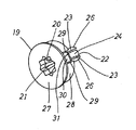
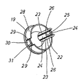
前述したようにヘアカーラー1は中空であるから、このままではハンドル11と結合することができない。そこで、結合するための部材が図5及び図6に示す蓋19である。蓋19は合成樹脂で形成されているが他の材料であってもよい。蓋19はヘアカーラー1の端部に取り付けて使用する。蓋19には孔部20が設けられている。孔部20は蓋19の表面側の前孔21と奥孔22とが連通している。前孔21はハンドル11の基軸15と合致するように形成され、内面に長さ方向に延びるように凹凸状部が形成されている。この凹凸状部とハンドル11の基軸15の表面に形成された凹凸状部とが合致して、ハンドル11がヘアカーラー1に対して回転することを防止する。凹凸状部の各山と溝底のそれぞれのピッチは45°にすることが好ましい。この角度であると前孔21にハンドル11の基軸15を合致させるためにはハンドル11の回転角度が45°よりも小さい角度で済むから迅速に合致させることができる。また、蓋19の表面部27に前記孔部20とは別に1又は複数の孔をあけることにより使用時における通風を良くすることができる。   Since the hair curler 1 is hollow as described above, it cannot be coupled to the handle 11 as it is. Therefore, the member for coupling is the lid 19 shown in FIGS. The lid 19 is made of a synthetic resin, but other materials may be used. The lid 19 is used by being attached to the end of the hair curler 1. The lid 19 is provided with a hole 20. The hole 20 communicates with the front hole 21 and the back hole 22 on the surface side of the lid 19. The front hole 21 is formed so as to coincide with the base shaft 15 of the handle 11, and an uneven portion is formed on the inner surface so as to extend in the length direction. This concavo-convex portion and the concavo-convex portion formed on the surface of the base shaft 15 of the handle 11 are matched to prevent the handle 11 from rotating with respect to the hair curler 1. It is preferable that the pitch between each peak of the concavo-convex portion and the groove bottom is 45 °. With this angle, the rotation angle of the handle 11 can be less than 45 ° in order to match the base shaft 15 of the handle 11 with the front hole 21, so that it can be quickly matched. In addition, ventilation at the time of use can be improved by making one or a plurality of holes separately from the hole portion 20 in the surface portion 27 of the lid 19.

奥孔22には一対の切り込み23,23が設けられ、その切り込み23,23の中に可撓性を有する係合片24,24が形成されている。蓋19を合成樹脂で一体に形成すれば係合片24,24は可撓性を有する。係合片24,24の端部に内向きの係合突部25,25(一方は図示せず。)が形成されている。ハンドル11の挿入部14を孔部20に挿入したときに、軸部16に設けた係合溝17と係合突部25,25が係合してハンドル11の抜け出しを防止する。この係合突部25,25の断面形状は例えば半円形や三角形などのように頂点の両側から底辺まで斜辺で裾広がりであることが好ましい。直線の斜辺でもよく曲線の斜辺でもよい。その斜辺の一方が垂直であったり他方の斜辺の方に食い込む裾広がりでない形状であるときは、係合溝17の断面形状を滑らかな弧状に形成することが好ましい。例えば、半円形やそれよりも小さな円弧状などであるがこれに限定されるものではない。このようにすることによって、ハンドル11の挿入部14を孔部20に挿入したときに、その軸線方向の力のみで簡単に係合することができる。それと同様に、軸線方向の力のみでヘアカーラー1とハンドル11を簡単に分離することができる。   The back hole 22 is provided with a pair of cuts 23, 23, and flexible engagement pieces 24, 24 are formed in the cuts 23, 23. If the lid 19 is integrally formed of synthetic resin, the engaging pieces 24 and 24 have flexibility. Inwardly-engaging engagement protrusions 25, 25 (one not shown) are formed at the ends of the engagement pieces 24, 24. When the insertion portion 14 of the handle 11 is inserted into the hole portion 20, the engagement groove 17 provided in the shaft portion 16 and the engagement protrusions 25 and 25 are engaged to prevent the handle 11 from coming off. It is preferable that the cross-sectional shape of the engaging protrusions 25 and 25 is a hem that extends obliquely from both sides of the apex to the base, such as a semicircle or a triangle. It may be the hypotenuse of a straight line or the hypotenuse of a curve. When one of the hypotenuses is vertical or has a shape that does not spread toward the other hypotenuse, the engagement groove 17 is preferably formed in a smooth arc shape. For example, it is a semicircular shape or a smaller arc shape, but is not limited thereto. By doing in this way, when the insertion part 14 of the handle 11 is inserted into the hole part 20, it can be easily engaged only with the axial force. Similarly, the hair curler 1 and the handle 11 can be easily separated only by the axial force.

図9に示すように、ヘアカーラー1の他方の端部側からもハンドル11の軸部16を奥孔22に挿入することができる。このとき、切り込み23,23によって分割された奥孔22の両側面26,26は係合片24,24よりも長いので、軸部16は両側面26,26の係合片24,24よりも突出している部分で安定的に支持される。したがって、使用後にハンドル11をこのように支持することによりコンパクトに保管しておくことができる。また、ハンドル11を短くした状態で使用することもできる。この場合、ハンドル11はヘアカーラー1に対して回転する。したがって、使用後に頭部に残っているヘアカーラー1を外すときに、図9のようにハンドル11をヘアカーラー1に取り付ければ、ハンドル11を持って巻き付いている毛髪をほどく方向に移動させることによりヘアカーラー1は自動的に回転して毛髪をほどくことができる。 As shown in FIG. 9, the shaft portion 16 of the handle 11 can be inserted into the back hole 22 also from the other end side of the hair curler 1. At this time, since both side surfaces 26 and 26 of the back hole 22 divided by the notches 23 and 23 are longer than the engagement pieces 24 and 24, the shaft portion 16 is longer than the engagement pieces 24 and 24 of the both side surfaces 26 and 26. It is supported stably at the protruding part. Therefore, it can be kept compact by supporting the handle 11 in this way after use. It can also be used with the handle 11 shortened. In this case, the handle 11 rotates with respect to the hair curler 1. Therefore, when the hair curler 1 remaining on the head after use is removed, if the handle 11 is attached to the hair curler 1 as shown in FIG. 9, the hair curled with the handle 11 is moved in the unwinding direction. The hair curler 1 can automatically rotate to unwind the hair.

蓋19の表面部27の裏側に、表面部27の外周よりもやや内側寄りに周面部28が形成されている。周面部28に一対の切り込み29,29が設けられ、その中に可撓性を有する係合片30,30(一方は図示せず。)が形成されている。係合片30,30の端部にそれぞれ外向きの係合突起31,31(一方は図示せず。)が形成されている。表面部27と対向する係合突起31,31の面は垂直に立ち上がった面であることが好ましい。この蓋19をヘアカーラー1の端部に取り付けるときは、蓋19の裏側からヘアカーラー1の端部に押し込む。そうすると、係合突起31,31が、芯部材2の最も端部側にある横枠部6を乗り越えて通孔7に入り、前記横枠部6に係合して取り付けが完了する。また、係合突起31,31が縦枠部5に係合することにより、蓋19がヘアカーラー1に対して回転することを防止できる。蓋19はヘアカーラー1の製造時に装着しておくことが好ましい。そのときは、最初の使用時に使用者が装着する必要はないので手間を省くことができる。また、蓋19をヘアカーラー1に着脱自在にするようにして使用者が蓋19の装着を選択することができるようにしてもよい。蓋19を装着しないことによって毛髪の巻き付けはヘアカーラー1のみの重さとなって軽くすることができる。 On the back side of the surface portion 27 of the lid 19, a peripheral surface portion 28 is formed slightly closer to the inside than the outer periphery of the surface portion 27. A pair of cuts 29, 29 are provided in the peripheral surface portion 28, and flexible engagement pieces 30, 30 (one not shown) are formed therein. Outward engagement protrusions 31 and 31 (one is not shown) are formed at the ends of the engagement pieces 30 and 30, respectively. It is preferable that the surfaces of the engagement protrusions 31, 31 facing the surface portion 27 are surfaces that rise vertically. When the lid 19 is attached to the end of the hair curler 1, the lid 19 is pushed into the end of the hair curler 1 from the back side of the lid 19. Then, the engagement protrusions 31, 31 get over the horizontal frame portion 6 located on the most end side of the core member 2 and enter the through hole 7 to engage with the horizontal frame portion 6 to complete the attachment. Further, the engagement protrusions 31, 31 engage with the vertical frame portion 5, whereby the lid 19 can be prevented from rotating with respect to the hair curler 1. The lid 19 is preferably attached at the time of manufacturing the hair curler 1. In that case, since it is not necessary for the user to wear it at the first use, time and effort can be saved. Further, the lid 19 may be detachably attached to the hair curler 1 so that the user can select attachment of the lid 19. By not attaching the lid 19, the hair can be wound only by the weight of the hair curler 1 and lightened.

次に、ハンドル11付きヘアカーラー1の使用方法について説明する。まず、蓋19の孔部20にハンドル11の挿入部14を挿入し、係合溝17と係合突部25を係合する。次いで、ハンドル11を手で持って回転させるとヘアカーラー1も同時に回転するから、ヘアカーラー1を回転させながら毛髪を巻き付ける。巻き付けが完了したら、例えば親指の腹をハンドル11の凹の湾曲面18に宛がうと共に、親指の指先を蓋19の表面部27に宛がって押すとヘアカーラー1はハンドル11から押し出されて両者を分離することができる。この作業を次々にすることによって複数のヘアカーラー1を頭に付けることができる。 Next, how to use the hair curler 1 with the handle 11 will be described. First, the insertion portion 14 of the handle 11 is inserted into the hole 20 of the lid 19, and the engagement groove 17 and the engagement protrusion 25 are engaged. Next, when the handle 11 is held and rotated, the hair curler 1 also rotates at the same time, so that the hair is wound while the hair curler 1 is rotated. When the winding is completed, the hair curler 1 is pushed out of the handle 11 by, for example, placing the belly of the thumb against the concave curved surface 18 of the handle 11 and pushing the fingertip of the thumb against the surface portion 27 of the lid 19. Can be separated. By repeating this operation one after another, a plurality of hair curlers 1 can be attached to the head.

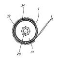
補助カーラー32は、図7に示すように断面がC字形に形成された芯部材33の表面に毛髪巻き付け部材34を装着したものである。これらの間に金属部材を装着してもしなくてもよい。芯部材33はヘアカーラー1の芯部材2と同じ材料で形成することが好ましいが、他の材料で形成してもよい。構造についても、ヘアカーラー1と同じように複数の縦枠部35と横枠部36で仕切られた複数の通孔37を設けてもよいが設けなくてもよい。すなわち、補助カーラー32は、形状が異なるが構造や材料はヘアカーラー1の芯部材2と同じでよい。また、同じでなくてもよい。芯部材33は可撓性を有している。断面がC字形に形成された芯部材33の内径はヘアカーラー1全体の外径とほぼ同じ大きさが好ましい。 As shown in FIG. 7, the auxiliary curler 32 has a hair wrapping member 34 mounted on the surface of a core member 33 having a C-shaped cross section. A metal member may or may not be mounted between them. The core member 33 is preferably formed of the same material as the core member 2 of the hair curler 1, but may be formed of other materials. As for the structure, a plurality of through holes 37 partitioned by a plurality of vertical frame portions 35 and horizontal frame portions 36 may be provided as in the hair curler 1 or not. That is, the auxiliary curler 32 may have the same structure and material as the core member 2 of the hair curler 1 although the shape is different. Moreover, it does not need to be the same. Core member 33 has flexibility. The inner diameter of the core member 33 having a C-shaped cross section is preferably approximately the same as the outer diameter of the entire hair curler 1.

補助カーラー32は毛髪を巻き付けたヘアカーラー1の上に重ねるものであるから、補助カーラー32の周面には頭皮から延びている毛髪を通す開放部が必要である。補助カーラー32の断面をC字形に形成したときは、周面の一部が全長に亘って切り取られているからその部分が開放部38となる。そして、芯部材33が可撓性を有するときは開放部38を押し広げることによりヘアカーラー1に重ねることができる。 Since the auxiliary curler 32 is placed on the hair curler 1 around which the hair is wound, an opening for passing the hair extending from the scalp is required on the peripheral surface of the auxiliary curler 32. When the cross section of the auxiliary curler 32 is formed in a C shape, a part of the peripheral surface is cut out over the entire length, so that part becomes the open part 38. And when the core member 33 has flexibility, it can be piled up on the hair curler 1 by expanding the open part 38 .

次に補助カーラー32の使用方法について説明する。まず、図8に示すようにハンドル11付きヘアカーラー1に毛髪をある程度巻き付け、その毛髪の上に補助カーラー32を重ねる。次いで、その補助カーラー32の外周面に毛髪をさらに巻き付ける。次いで前述した方法でハンドル11をヘアカーラー1から分離する。補助カーラー32はヘアカーラー1に巻き付けた毛髪がほどけることを確実に防止し、補助カーラー32の表面にも毛髪を巻き付けることにより巻き付け中に毛髪がほどけることがなく迅速に巻き付け作業をすることができる。また、複数の補助カーラー32を重ねて用いることもできることは勿論である。 Next, how to use the auxiliary curler 32 will be described. First, as shown in FIG. 8, hair is wound around the hair curler 1 with the handle 11 to some extent, and the auxiliary curler 32 is overlaid on the hair. Next, the hair is further wound around the outer peripheral surface of the auxiliary curler 32. Next, the handle 11 is separated from the hair curler 1 by the method described above. The auxiliary curler 32 reliably prevents the hair wound around the hair curler 1 from unwinding, and the hair is also wound around the surface of the auxiliary curler 32 so that the hair is not unwound during winding and the hair is quickly wound. Can do. Of course, a plurality of auxiliary curlers 32 can be used in a stacked manner.

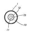
ヘアカーラーとハンドルを分離した状態の正面図Front view of hair curler and handle separated ヘアカーラーとハンドルを結合した状態の正面図Front view of hair curler and handle combined 図2における右側面図Right side view in FIG. 巻き付け部を広げたヘアカーラーの斜視図Perspective view of hair curler with widened winding 蓋をその表面部側から見た斜視図The perspective view which looked at the lid from the surface part side 蓋をその裏側から見た斜視図The perspective view which looked at the lid from the back side 補助カーラーの斜視図Auxiliary curler perspective view 毛髪を巻き付けたヘアカーラーに補助カーラーを重ねた側面図Side view of auxiliary curlers superimposed on hair curlers wrapped with hair ハンドルをヘアカーラーに逆方向から係合させた正面図Front view with handle engaged with hair curler from opposite direction

1 ヘアカーラー、 2 芯部材、 3 金属部材、 4 毛髪巻き付け部材、 5 縦枠部、 6 横枠部、 7 通孔、 8 通孔、 9 生地、 10 フック状繊維、 11 ハンドル、 12 基端、 13 突条、 14 挿入部、 15 基軸、 16 軸部、 17 係合溝、 18 湾曲面、 19 蓋、 20 孔部、 21 前孔、 22 奥孔、 23 切り込み、 24 係合片、 25 係合突部、 26 奥孔の側面、 27 蓋の表面部、 28 周面部、 29 切り込み、 30 係合片、 31 係合突起、 32 補助カーラー、 33 芯部材、 34 毛髪巻き付け部材、 35 縦枠部、 36 横枠部、 37 通孔、 38 開放部、 39 ハンドルの後端
DESCRIPTION OF SYMBOLS 1 Hair curler, 2 Core member, 3 Metal member, 4 Hair winding member, 5 Vertical frame part, 6 Horizontal frame part, 7 Through hole, 8 Through hole, 9 Fabric, 10 Hook-like fiber, 11 Handle, 12 Base end, 13 ridges, 14 insertion portions, 15 base shafts, 16 shaft portions, 17 engagement grooves, 18 curved surfaces, 19 lids, 20 hole portions, 21 front holes, 22 back holes, 23 cuts, 24 engagement pieces, 25 engagements Projection, 26 Back hole side, 27 Cover surface, 28 Peripheral surface, 29 Cut, 30 Engagement piece, 31 Engagement projection, 32 Auxiliary curler, 33 Core member, 34 Hair winding member, 35 Vertical frame part, 36 horizontal frame, 37 through hole, 38 opening, 39 rear end of handle

Claims (1)

可撓性を有し断面がC字形に形成された芯部材の表面に多数のフック状繊維である毛髪の巻き付け部が設けられ、ヘアカーラーの外周面上の一部に重ね合わせ可能の形状に形成され、且つヘアカーラーに巻き付けられた毛髪の上に重ねることができるように形成され、芯部材の外周面に多数のフック状繊維である毛髪の巻き付け部を設けた前記ヘアカーラーの外周面上に着脱自在に取り付けることができることを特徴とする補助カーラー。 The core member, which is flexible and has a C-shaped cross- section, is provided with a number of hook-like fiber wraps around the surface of the core member, and can be superimposed on a part of the outer peripheral surface of the hair curler. On the outer peripheral surface of the hair curler, which is formed and can be superimposed on the hair wound around the hair curler, and provided with a hair wrapping portion which is a large number of hook-like fibers on the outer peripheral surface of the core member Auxiliary curler characterized in that it can be detachably attached to .
JP2007086535A 2007-03-29 2007-03-29 Auxiliary curler for hair curlers Expired - Fee Related JP5383003B2 (en)

Priority Applications (1)

Application Number Priority Date Filing Date Title
JP2007086535A JP5383003B2 (en) 2007-03-29 2007-03-29 Auxiliary curler for hair curlers

Applications Claiming Priority (1)

Application Number Priority Date Filing Date Title
JP2007086535A JP5383003B2 (en) 2007-03-29 2007-03-29 Auxiliary curler for hair curlers

Publications (2)

Publication Number Publication Date
JP2008237821A JP2008237821A (en) 2008-10-09
JP5383003B2 true JP5383003B2 (en) 2014-01-08

Family

ID=39909844

Family Applications (1)

Application Number Title Priority Date Filing Date
JP2007086535A Expired - Fee Related JP5383003B2 (en) 2007-03-29 2007-03-29 Auxiliary curler for hair curlers

Country Status (1)

Country Link
JP (1) JP5383003B2 (en)

Families Citing this family (1)

* Cited by examiner, † Cited by third party
Publication number Priority date Publication date Assignee Title
IT201700016085A1 (en) * 2017-02-14 2018-08-14 Kemon S P A ACCESSORY AND METHOD FOR SELECTIVE HAIR COLORING

Family Cites Families (4)

* Cited by examiner, † Cited by third party
Publication number Priority date Publication date Assignee Title
JPS539396Y2 (en) * 1972-12-25 1978-03-11
JPS551468U (en) * 1978-06-21 1980-01-08
JPH0666501U (en) * 1993-03-03 1994-09-20 英伸 岩田 Large diameter curler for beauty
JPH08242928A (en) * 1995-03-08 1996-09-24 Kanroku Oohashi Winding tool of hair curler

Also Published As

Publication number Publication date
JP2008237821A (en) 2008-10-09

Similar Documents

Publication Publication Date Title
JP2006015121A (en) Hair curling tool and method of curling hair
US20150366314A1 (en) Hair styling device with grip-tip
KR102545387B1 (en) Hair styling device for hair curling with stationary fingers for binding and releasing strands
RU2700918C2 (en) Electric hair curler
JP5383003B2 (en) Auxiliary curler for hair curlers
TWI451847B (en) Tying tool for restoring hair and method of using the same
WO2015041356A1 (en) Holder for material for increasing hair volume
KR102631041B1 (en) Automatic hairstyling device for curling hair with hair immobilizing device
US20090084397A1 (en) Perm rod
JP3989012B2 (en) Film roll container
KR102547525B1 (en) Hair styling device for hair curling with inclined mandrel and winder
KR101073720B1 (en) Perming device for root part of hair
JP2007119212A (en) Winding device for bandage or the like
US20210153718A1 (en) Tape cleaner
JP5118536B2 (en) fishing rod
JP5269246B1 (en) Permanent wave aid
JP5512867B1 (en) Hair wave forming method
KR20160002769U (en) Hair roller
JP5335567B2 (en) Case for spool
JP2018089174A (en) Cutter for adhesive tape roll cleaner
JP2009255935A (en) Opener for bottle or the like
JP6960368B2 (en) scissors
KR200486615Y1 (en) Hair roll for hair root volume permanent
JP3160745U (en) Perm hairdressing rod winding tool
JP4512572B2 (en) Roller hairdresser

Legal Events

Date Code Title Description
A621 Written request for application examination

Free format text: JAPANESE INTERMEDIATE CODE: A621

Effective date: 20100323

A977 Report on retrieval

Free format text: JAPANESE INTERMEDIATE CODE: A971007

Effective date: 20111213

A131 Notification of reasons for refusal

Free format text: JAPANESE INTERMEDIATE CODE: A131

Effective date: 20111215

A521 Request for written amendment filed

Free format text: JAPANESE INTERMEDIATE CODE: A523

Effective date: 20120208

A131 Notification of reasons for refusal

Free format text: JAPANESE INTERMEDIATE CODE: A131

Effective date: 20120521

A521 Request for written amendment filed

Free format text: JAPANESE INTERMEDIATE CODE: A523

Effective date: 20120719

A521 Request for written amendment filed

Free format text: JAPANESE INTERMEDIATE CODE: A821

Effective date: 20120720

A02 Decision of refusal

Free format text: JAPANESE INTERMEDIATE CODE: A02

Effective date: 20121205

A521 Request for written amendment filed

Free format text: JAPANESE INTERMEDIATE CODE: A523

Effective date: 20130304

A911 Transfer to examiner for re-examination before appeal (zenchi)

Free format text: JAPANESE INTERMEDIATE CODE: A911

Effective date: 20130321

A912 Re-examination (zenchi) completed and case transferred to appeal board

Free format text: JAPANESE INTERMEDIATE CODE: A912

Effective date: 20130531

A61 First payment of annual fees (during grant procedure)

Free format text: JAPANESE INTERMEDIATE CODE: A61

Effective date: 20131001

R150 Certificate of patent or registration of utility model

Ref document number: 5383003

Country of ref document: JP

Free format text: JAPANESE INTERMEDIATE CODE: R150

Free format text: JAPANESE INTERMEDIATE CODE: R150

R250 Receipt of annual fees

Free format text: JAPANESE INTERMEDIATE CODE: R250

R250 Receipt of annual fees

Free format text: JAPANESE INTERMEDIATE CODE: R250

R250 Receipt of annual fees

Free format text: JAPANESE INTERMEDIATE CODE: R250

R250 Receipt of annual fees

Free format text: JAPANESE INTERMEDIATE CODE: R250

R250 Receipt of annual fees

Free format text: JAPANESE INTERMEDIATE CODE: R250

R250 Receipt of annual fees

Free format text: JAPANESE INTERMEDIATE CODE: R250

LAPS Cancellation because of no payment of annual fees