JP5382960B2 - Seismic isolation device with a damper type damping mechanism. - Google Patents
Seismic isolation device with a damper type damping mechanism. Download PDFInfo
- Publication number
- JP5382960B2 JP5382960B2 JP2011537081A JP2011537081A JP5382960B2 JP 5382960 B2 JP5382960 B2 JP 5382960B2 JP 2011537081 A JP2011537081 A JP 2011537081A JP 2011537081 A JP2011537081 A JP 2011537081A JP 5382960 B2 JP5382960 B2 JP 5382960B2
- Authority
- JP
- Japan
- Prior art keywords
- seismic isolation
- isolation device
- damping mechanism
- cylindrical
- cylindrical material
- Prior art date
- Legal status (The legal status is an assumption and is not a legal conclusion. Google has not performed a legal analysis and makes no representation as to the accuracy of the status listed.)
- Expired - Fee Related
Links
Images


Classifications
-
- E—FIXED CONSTRUCTIONS
- E04—BUILDING
- E04H—BUILDINGS OR LIKE STRUCTURES FOR PARTICULAR PURPOSES; SWIMMING OR SPLASH BATHS OR POOLS; MASTS; FENCING; TENTS OR CANOPIES, IN GENERAL
- E04H9/00—Buildings, groups of buildings or shelters adapted to withstand or provide protection against abnormal external influences, e.g. war-like action, earthquake or extreme climate
- E04H9/02—Buildings, groups of buildings or shelters adapted to withstand or provide protection against abnormal external influences, e.g. war-like action, earthquake or extreme climate withstanding earthquake or sinking of ground
- E04H9/021—Bearing, supporting or connecting constructions specially adapted for such buildings
- E04H9/023—Bearing, supporting or connecting constructions specially adapted for such buildings and comprising rolling elements, e.g. balls, pins
-
- F—MECHANICAL ENGINEERING; LIGHTING; HEATING; WEAPONS; BLASTING
- F16—ENGINEERING ELEMENTS AND UNITS; GENERAL MEASURES FOR PRODUCING AND MAINTAINING EFFECTIVE FUNCTIONING OF MACHINES OR INSTALLATIONS; THERMAL INSULATION IN GENERAL
- F16F—SPRINGS; SHOCK-ABSORBERS; MEANS FOR DAMPING VIBRATION
- F16F7/00—Vibration-dampers; Shock-absorbers
- F16F7/12—Vibration-dampers; Shock-absorbers using plastic deformation of members
- F16F7/123—Deformation involving a bending action, e.g. strap moving through multiple rollers, folding of members
-
- F—MECHANICAL ENGINEERING; LIGHTING; HEATING; WEAPONS; BLASTING
- F16—ENGINEERING ELEMENTS AND UNITS; GENERAL MEASURES FOR PRODUCING AND MAINTAINING EFFECTIVE FUNCTIONING OF MACHINES OR INSTALLATIONS; THERMAL INSULATION IN GENERAL
- F16F—SPRINGS; SHOCK-ABSORBERS; MEANS FOR DAMPING VIBRATION
- F16F2230/00—Purpose; Design features
- F16F2230/14—Ball joints; Spherical support elements
Description
本発明は、特願2006−539143で提案している免震装置において、コロ形式の上下に直交するコロ支承機構における、上下コロの直交角度の固定機構、並びに、減衰力を制御抑制する機能を有するダンパー形式の減衰機構を、前記免震装置に付与した技術に関する。 In the seismic isolation device proposed in Japanese Patent Application No. 2006-539143, the present invention has a mechanism for fixing the vertical angle of the upper and lower rollers and a function for controlling and suppressing the damping force in the roller support mechanism perpendicular to the upper and lower rollers. The present invention relates to a technology in which a damper-type damping mechanism is provided to the seismic isolation device.
地震による構造物の損壊を免れるには、構造物を強固に作る方法が最良であるとされていたが、如何に構造物を強固にしても構造物の揺れを抑制しない限り、家財の転倒落下等によって身体が受ける危険は避けられない。 The best way to avoid damage to the structure due to an earthquake was to make the structure strong. However, unless the structure is strengthened, it will not fall down unless the shaking of the structure is suppressed. The risk that the body suffers due to etc. is inevitable.
これを解決する方法として地盤から受ける揺れを吸収するために、基礎などの下部構造と免震対象構造物である上部構造に分け、両構造物の間に支承機能・位置復帰機能・減衰機能を構築し、免震装置とし構造物を揺れなくすることが有効であることが知られている。 In order to solve this problem, in order to absorb the shaking received from the ground, it is divided into a lower structure such as a foundation and an upper structure that is a seismic isolation target structure, and a bearing function, position return function, and damping function are provided between both structures. It is known that it is effective to build a seismic isolation device to prevent the structure from shaking.
免震装置は各種開発されているが、住宅等の軽量構造物から大型構造物までの汎用性をもって利用できる装置は少なく、汎用性のある装置の開発が望まれている。 Although various types of seismic isolation devices have been developed, there are few devices that can be used with versatility from lightweight structures such as houses to large structures, and the development of versatile devices is desired.
既存の装置は使用材料がゴム・鉛・合成油・合成樹脂・鋼材等を用い高度な技術を要する他、劣化する材料が含まれていたり、機構が内部構造を持ち部品の精度も精密性を必要とする他、特定の製造業者、特定の材料を必要としたり、高度な加工技術や特殊な工作機械が必要である事が多く製造量も少ないため高価となり普及していない、又、長期に亘る使用期間において専門的視点からの点検部品交換等も必要となる他、内部構造の点検はできにくく維持管理上も好ましくない。 The existing equipment uses materials such as rubber, lead, synthetic oil, synthetic resin, steel, etc. and requires advanced technology. Also, it contains deteriorated materials, and the mechanism has an internal structure and the accuracy of parts is also precise. In addition to the need, specific manufacturers, specific materials are required, advanced processing techniques and special machine tools are often required, and the amount of production is small, so it is expensive and not popular. In addition to the need for replacement of inspection parts from a specialized point of view over a long period of use, it is difficult to inspect the internal structure, which is not preferable for maintenance.
大地震域の水平力が及ぶ免震構造物に、ダンパーなどにより減衰機能を与えないと免震構造物は逸走し、過度もしくは不安定な揺れを起こすこともあるので、通常免震装置には減衰機構を備えている。 Since the seismic isolation structure may run away and cause excessive or unstable shaking unless a damping function is applied to the seismic isolation structure that is affected by the horizontal force in a large earthquake area, A damping mechanism is provided.
既存の減衰機構は一般的に対象とする最大地震域のエネルギー吸収量を基準とした減衰能力を持っているので、小さな地震力に対しては、大地震を基にした減衰能力では過大となり、減衰機能とは相対的な機能である支承機構の持つ水平力緩衝機能が阻害されるので、小さな地震の場合に免震装置を設置しているにも関わらず、減衰能力の過大さから構造物が揺れる結果となり解決策が望まれている。 The existing damping mechanism generally has a damping capacity based on the energy absorption amount of the target maximum earthquake area, so for a small seismic force, the damping capacity based on a large earthquake is excessive, Since the horizontal force buffering function of the support mechanism, which is a relative function to the damping function, is obstructed, the structure will be damaged due to the excessive damping capacity even though a seismic isolation device is installed in the case of a small earthquake. As a result, a solution is desired.
このような揺れを回避するためには、地震の大きさに対応して、減衰力を制御抑制する必要があるが、機械的に減衰力を簡易に制御抑制する方法は確立されていない。 In order to avoid such shaking, it is necessary to control and suppress the damping force in accordance with the magnitude of the earthquake, but a method for easily controlling and suppressing the damping force has not been established.
免震装置の、支承機構であるX・Y方向の上下に重なって直交しているコロ相互の水平接触面での捩れを防止し、コロの直交角度を保ち減衰機構の安定的作動に資する機構を備えた免震装置を提供することを第1の課題とすると共に、前記減衰機構の減衰力を機械的に制御抑制できる作動原理を究明し、免震装置における新たな形式の減衰機構を提供することを第2の課題とする。 A mechanism that contributes to stable operation of the damping mechanism by preventing the twisting of the horizontal contact surfaces of the rollers that are perpendicular to each other in the X and Y directions, which is the support mechanism of the seismic isolation device, while maintaining the orthogonal angle of the rollers. The first problem is to provide a seismic isolation device equipped with a shock absorber, and the operating principle that can mechanically control the damping force of the damping mechanism is investigated, and a new type of damping mechanism in the seismic isolation device is provided. This is a second problem.
本発明は課題1を解決するために、上下に重なって直交するコロ(3)と(4)の直交角度を保つ為に、コロ(3)と(4)の転動を許容する僅かな空隙をもつが、直交角度の変位は許容しないU型断面を持つ鋼板製の拘束材(9)と(10)を、コロ(3)と(4)に、上下から直交部分にU型断面の解放側を対面的にかぶせ、該解放側先端部分を外側に直角に折り曲げ、折り曲げ面に4本の結合ボルト用の孔を開け、拘束材(9)と(10)の接触面を堅固に結合ボルト(11)によって結合し、コロ(3)と(4)の捩れを防止できる直交角度固定機構によって減衰機構の作動環境を整えた。 「請求項1」
In order to solve the
課題2を解決するために上記固定機構を備えた免震装置における減衰機構の構成は、塑性材である線状の鋼材(14)を外側円筒材(13)に巻き付け、線状の鋼材(14)と外側円筒材(13)が相対的に変位することによる、線状の鋼材(14)の変形に伴うエネルギー吸収機能により減衰力を得られるようにした。 「請求項2」
In order to solve the
上記減衰機構の追加機能として、前記線状の鋼材(14)と外側円筒材(13)の相対的変位に、空隙(21)と(22)を設け、円筒材(12)に空走区間を与え下部構造(1)と上部構造(8)の間の水平変位エネルギー伝達を遮断し、外側円筒材(13)に巻き付けた線状の鋼材(14)の変形を止めエネルギー吸収機能を解除しエネルギー吸収の抑制を図った。 「請求項3・4」
As an additional function of the damping mechanism, gaps (21) and (22) are provided in the relative displacement of the linear steel material (14) and the outer cylindrical material (13), and an idle running section is provided in the cylindrical material (12). The horizontal displacement energy transmission between the lower structure (1) and the upper structure (8) is interrupted, the deformation of the linear steel material (14) wound around the outer cylindrical material (13) is stopped, and the energy absorbing function is released to release the energy. Absorption was suppressed. “
また、線状の鋼材(14)の軸方向断面積を変化させることによってエネルギー吸収量を変化させて制御する方法。 「請求項5」
Moreover, the method of changing and controlling an energy absorption amount by changing the axial direction cross-sectional area of a linear steel material (14). “
更に、線状の鋼材(14)を右巻き、左巻き本数を同数とするか、又は、左巻き、右巻き方向の軸方向抵抗力が同一となる断面積とする方法によって、取り付け時に外側円筒材(13)に作用する偶力を除き外側円筒材の捩れを止め減衰機構の作動環境の安定を図った。 「請求項6」
Furthermore, the outer cylindrical material (14) is attached to the outer cylindrical material (14) by the right-handed and left-handed number of the same or the cross-sectional area having the same axial resistance in the left-handed and right-handed directions. Except for the couple acting on 13), the outer cylindrical member was prevented from being twisted to stabilize the operating environment of the damping mechanism. “
以上の通り本発明による免震装置に適用して有用なコロの直交角度固定機構、並びに、減衰機構は簡易な仕組みで構成され使用素材も鋼材に統一され、部品の形状も簡易であり複雑な形状や内部構造をもたない、従って、製造時には汎用工作機械を用いて市販規格鋼材を切断、曲げ、溶接、防錆メッキ加工して軽量構造物から大型構造物まで、汎用性をもって容易に製造できる構造である。 As described above, the roller orthogonal angle fixing mechanism useful for application to the seismic isolation device according to the present invention, and the damping mechanism are configured with a simple mechanism, the material used is unified with steel, and the shape of the parts is simple and complicated. It has no shape or internal structure. Therefore, it can be easily manufactured with versatility from light to large structures by cutting, bending, welding, and anti-rust plating of commercial standard steel using a general-purpose machine tool during manufacturing. It is a possible structure.
しかも上記構成部材には、劣化する材料、高価な材料、特殊な工作機械や特殊な工程、特定の材料業者、特定の製造業者等の協力は必要としないので、極めて安価に製造できる。 In addition, the above-described components do not require the cooperation of a deteriorated material, an expensive material, a special machine tool, a special process, a specific material supplier, a specific manufacturer, and the like, and therefore can be manufactured at a very low cost.
又、本発明装置の使用開始後は構成部品の劣化、機能の低下もなく、部品の交換なども通常必要ない、装置の作動状態も外観目視により確認可能であり、長期に亘り安定的に機能が維持されなければならない免震装置に求められる、各種要求を充分に満たすことができるので、構造物に設置されるなら、地震災害の防止に効果が期待できる。 In addition, after the start of use of the device of the present invention, there is no deterioration of the component parts, deterioration of the function, replacement of the components or the like is usually unnecessary, and the operation state of the device can be confirmed by visual observation, and the device functions stably for a long time. Since it can sufficiently satisfy various requirements for seismic isolation devices that must be maintained, if installed in a structure, it can be expected to be effective in preventing earthquake disasters.
以下、本件発明を実施する形態を図1〜図10に基づいて説明する。 Hereinafter, embodiments for carrying out the present invention will be described with reference to FIGS.
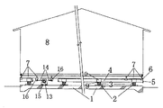
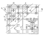
図1に示す上部構造(8)が水平方向に変位したとき、支承機構である上下に直交したコロ(3)と(4)はそれぞれ負担する方向、XとYの方向に転動し水平力を緩衝する、この時上部構造に偏心力が作用すると、図2に示すコロ(3)と(4)の直交角度は捩られ、減衰機構である円筒材(12)外側円筒材(13)と線状の鋼材(14)の交差角度も捩られ、減衰機構の作動に支承を及ぼすので、図5に示す支承機構である、上下に重なって直交するコロ(3)と(4)の直交角度を保つ為に、コロ(3)と(4)の転動を許容する僅かな空隙をもつが直交角度の変位は許容しないU型断面を持つ鋼板製の拘束材(9)と(10)を、コロ(3)と(4)に上下から直交部分にU型断面の解放側を直交する向きに対面的にかぶせ、該解放側先端部分を外側に直角に折り曲げ、折り曲げ面に4本の結合ボルト用の孔を開け、拘束材(9)と(10)の接触面を堅固に結合ボルト(11)によって結合し、コロ(3)と(4)の直交角度固定機構とし、減衰機構である図6に示す円筒材(12)に対して線状の鋼材(14)の軸方向が直角となり、図9に示す円筒材(12)と外側円筒材(13)の空隙(21)、図10に示す円筒材(12)と支持材(15)の取付け支持穴(22)の各接触面の均衡を確保して、減衰機構の安定的作動の条件を整えた。 When the superstructure (8) shown in FIG. 1 is displaced in the horizontal direction, the rollers (3) and (4) that are perpendicular to the support mechanism roll in the bearing direction, X and Y directions, respectively, and the horizontal force When an eccentric force acts on the superstructure at this time, the orthogonal angle between the rollers (3) and (4) shown in FIG. 2 is twisted, and the cylindrical material (12) and the outer cylindrical material (13) as a damping mechanism Since the crossing angle of the linear steel material (14) is also twisted and exerts a bearing on the operation of the damping mechanism, the orthogonal angle of the rollers (3) and (4) perpendicular to each other, which is the bearing mechanism shown in FIG. In order to keep the rolls, the restraints (9) and (10) made of steel plates having a U-shaped cross section with a slight gap allowing the rolling of the rollers (3) and (4) but not allowing the displacement at an orthogonal angle. Cover the rollers (3) and (4) in the direction perpendicular to the open side of the U-shaped cross section on the orthogonal part from the top and bottom. The side tip portion is bent outward at a right angle, four holes for connecting bolts are opened on the bent surface, and the contact surfaces of the restraining members (9) and (10) are firmly connected by the connecting bolt (11). The orthogonal angle fixing mechanism of 3) and (4) is used, and the axial direction of the linear steel material (14) is perpendicular to the cylindrical material (12) shown in FIG. 12) and a space (21) between the outer cylindrical member (13) and a balance between the contact surfaces of the mounting support holes (22) of the cylindrical member (12) and the supporting member (15) shown in FIG. The conditions for stable operation of the
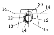
上部構造(8)に作用する水平力によって、下部構造(1)と上部構造(8)が相対的に水平方向に変位するとき、図6ないし図8に示す下部構造に固定した持ち送り支持材(15)は凹型コロ受け(2)(6)上を転動するコロ(3)(4)によって、上部構造と下部構造が垂直方向に変位する時の、円筒材(12)の上下動に必要な垂直方向の空隙を備えた取付け支持穴(20)を持って、円筒材(12)を支持し、円筒材(12)ないし外側円筒材(13)と上部構造に固定した、持ち送り支持材(16)と外側円筒材(13)に巻き付けた線状の鋼材(14)の部材の間にも水平変位が起こる、このとき外側円筒材(13)に巻き付く、線状の鋼材(14)は、1端は円形から直線状態に、他端は直線から円形状態に変形しエネルギー吸収作用が生じる、この水平力からエネルギー吸収作用を機械的に発生させる機構を基本減衰機構とし。 When the lower structure (1) and the upper structure (8) are relatively displaced in the horizontal direction by the horizontal force acting on the upper structure (8), the carrying support material fixed to the lower structure shown in FIGS. (15) is the vertical movement of the cylindrical member (12) when the upper structure and the lower structure are displaced vertically by the rollers (3) and (4) rolling on the concave roller receivers (2) and (6). A carrying support with a mounting support hole (20) with the required vertical gap, supporting the cylindrical material (12) and fixed to the cylindrical material (12) or outer cylindrical material (13) and superstructure. Horizontal displacement also occurs between the members of the linear steel material (14) wound around the material (16) and the outer cylindrical material (13). At this time, the linear steel material (14 wound around the outer cylindrical material (13) ) One end is deformed from a circular shape to a straight state, and the other end is deformed from a straight shape to a circular state. Absorption occurs, a mechanism for mechanically generating energy absorption from the horizontal force as a basic damping mechanism.
図9、図10に示す空隙(21)(22)と円筒材(12)の空走作用を基本減衰機構に加えた、該空走作用とは、上部構造(8)に生じる小さな地震の水平力に対して、基本減衰機構に備わるエネルギー吸収量が水平力の持つエネルギー量を上回るとき、上部構造(8)は水平力の持つエネルギー量が減衰機構のもつエネルギー吸収量を越えるまで揺れる、この揺れを回避するためには、線状の鋼材(14)に伝達される地震エネルギーを遮断する方法が考えられ、水平力の伝達機構である内側円筒材(12)ないし支持材(15)の間に、水平力遮断のための空走用空隙(21)と(22)を創成して、該空隙部分を円筒材(12)が水平方向に空走する間、減衰機能を解除して外側円筒材(13)が回転力を受けないようにし、線状の鋼材(14)のエネルギー吸収を抑制した、これによって該空隙間を振幅する小さな地震については減衰機能が及ばず、支承機構による水平力緩衝機能だけが作用する状態を創出し、小さな地震域の振幅に対して減衰力を機械的に抑制する機能を基本減衰機構に加え、目的とする小さな地震の揺れを抑制できる減衰機構とした。 9 and 10 is added to the basic damping mechanism, which is the horizontal run of a small earthquake occurring in the superstructure (8). When the energy absorption amount of the basic damping mechanism exceeds the energy amount of the horizontal force with respect to the force, the superstructure (8) swings until the energy amount of the horizontal force exceeds the energy absorption amount of the damping mechanism. In order to avoid shaking, a method of interrupting the seismic energy transmitted to the linear steel material (14) is conceivable, and between the inner cylindrical material (12) or the support material (15) which is a horizontal force transmission mechanism. In addition, gaps (21) and (22) for idle running for blocking horizontal force are created, and the damping function is released while the cylinder member (12) idles in the horizontal direction in the gap portion to release the outer cylinder. Prevent the material (13) from receiving rotational force, A small earthquake that suppresses the energy absorption of the material (14) and thus the amplitude of the air gap does not reach the damping function, and creates a state where only the horizontal force buffering function by the support mechanism acts, and the amplitude of the small earthquake area In addition to the basic damping mechanism, the damping mechanism that can suppress the vibration of the target small earthquake is added.
下部構造(1)と上部構造(8)が相対的に水平方向に変位するとき、線状の鋼材(14)と外側円筒材(13)の巻き付け部分に生じるエネルギー吸収の基本減衰機構に対し、線状の鋼材(14)の軸方向の断面積を連続的に変化させることによって、線状の鋼材(14)のエネルギー吸収量に連続的変化を与えることができ、線状の鋼材(14)の軸方向の振幅幅に応じて減衰力を機械的に制御する機能が得られ、これを基本減衰機構に加えた。 When the lower structure (1) and the upper structure (8) are relatively displaced in the horizontal direction, the basic damping mechanism for energy absorption generated in the winding portion of the linear steel material (14) and the outer cylindrical material (13), By continuously changing the axial cross-sectional area of the linear steel material (14), the energy absorption of the linear steel material (14) can be continuously changed, and the linear steel material (14). The function of mechanically controlling the damping force according to the amplitude width in the axial direction was obtained, and this was added to the basic damping mechanism.
図6に示す線状の鋼材(14)が奇数の場合、該線状の鋼材が外側円筒材(13)に巻き付く交差部分において、線状の鋼材が相反する軸方向に向き1直線上にないために、取り付け時に偶力が起こり、この偶力によって外側円筒材(13)に捩れを生じるので、偶力を相殺する為に線状の鋼材(14)を右巻き本数、左巻き本数を同数用いるか、又は、左巻き、右巻き方向の軸方向抵抗力が同一となる断面積とすることによって、偶力の影響を除き基本減衰機構の作動環境を整えた。 When the linear steel material (14) shown in FIG. 6 is an odd number, at the intersection where the linear steel material wraps around the outer cylindrical material (13), the linear steel material faces in the opposite axial direction on a straight line. Because there is no couple, a couple is generated at the time of installation, and this couple causes a twist in the outer cylindrical member (13). Therefore, in order to offset the couple, the number of the right-handed windings and the number of the left-handed windings are the same. The operating environment of the basic damping mechanism was adjusted except for the influence of couples by using or making the cross-sectional area the axial resistance force in the left-handed and right-handed directions to be the same.
以上、本実施例のごとく、本発明は簡潔な構造であるが、減衰機構の減衰力を機械的に抑制制御する構成を簡易な方法によって満たした新たな形式の減衰機構である。 As described above, although the present invention has a simple structure as in this embodiment, it is a new type of damping mechanism that satisfies the configuration for mechanically suppressing and controlling the damping force of the damping mechanism by a simple method.
1・・・は下部構造の基礎を示す。
2・・・は凹型コロ受け(下)を示す。
3・・・はコロ(下)を示す。
4・・・はコロ(上)を示す。
5・・・は突起板を示す。
6・・・は凹型コロ受け(上)を示す。
7・・・は上部構造の架台を示す。
8・・・は上部構造の構造物を示す。
9・・・はコロ拘束材(下)を示す。
10・・はコロ拘束材(上)を示す。
11・・はコロ拘束材結合ボルトを示す。
12・・は円筒材を示す。
13・・は外側円筒材を示す。
14・・は線状の鋼材を示す。
15・・は円筒材12の持ち送り支持材を示す。
16・・は線状の鋼材14の持ち送り支持材を示す。
17・・は「請求項4」の持ち送り支持材15に具備する支持穴を示す。
18・・は円筒材12の外端部に固定する持ち送り支持材15からの脱落防止材を示す。
19・・は持ち送り支持材15と基礎の固定ボルトを示す。
20・・は「請求項2」と「請求項3」の持ち送り支持材15に具備する支持穴を示す。
21・・は「請求項3」の円筒材12と外側円筒材13の間の空走用空隙を示す。
22・・は「請求項4」の持ち送り支持材15の支持穴17と円筒材12の間の空走用空隙を示す。1 ... indicates the foundation of the substructure.
2 ... indicates a concave roller receiver (bottom).
3 ... indicates a roller (bottom).
4 ... indicates a roller (top).
5 ... indicates a protruding plate.
6 ... indicates a concave roller receiver (top).
8 indicates a superstructure structure.
9 denotes a roller restraint material (bottom).
10 ·· indicates a roller restraint material (top).
12 ... indicates a cylindrical material.
14 ... indicates a linear steel material.
21... Indicate idle running gaps between the
Claims (6)
Applications Claiming Priority (1)
| Application Number | Priority Date | Filing Date | Title |
|---|---|---|---|
| PCT/JP2009/068446 WO2011048704A1 (en) | 2009-10-21 | 2009-10-21 | Seismic isolation system having damper-type damping mechanism |
Publications (2)
| Publication Number | Publication Date |
|---|---|
| JPWO2011048704A1 JPWO2011048704A1 (en) | 2013-03-07 |
| JP5382960B2 true JP5382960B2 (en) | 2014-01-08 |
Family
ID=43899950
Family Applications (1)
| Application Number | Title | Priority Date | Filing Date |
|---|---|---|---|
| JP2011537081A Expired - Fee Related JP5382960B2 (en) | 2009-10-21 | 2009-10-21 | Seismic isolation device with a damper type damping mechanism. |
Country Status (4)
| Country | Link |
|---|---|
| US (1) | US20120260586A1 (en) |
| JP (1) | JP5382960B2 (en) |
| CN (1) | CN102575484A (en) |
| WO (1) | WO2011048704A1 (en) |
Families Citing this family (5)
| Publication number | Priority date | Publication date | Assignee | Title |
|---|---|---|---|---|
| US8857110B2 (en) * | 2011-11-11 | 2014-10-14 | The Research Foundation For The State University Of New York | Negative stiffness device and method |
| US20150136939A1 (en) * | 2012-05-30 | 2015-05-21 | Stuart Haselden | Support system |
| US9206616B2 (en) | 2013-06-28 | 2015-12-08 | The Research Foundation For The State University Of New York | Negative stiffness device and method |
| CN103590327B (en) * | 2013-11-25 | 2015-11-11 | 中铁第四勘察设计院集团有限公司 | Hoop viscous damping bearing |
| IT201600119806A1 (en) * | 2016-11-25 | 2018-05-25 | Mauro Laudazi | SEISMIC ISOLATOR |
Citations (4)
| Publication number | Priority date | Publication date | Assignee | Title |
|---|---|---|---|---|
| JPS57140453A (en) * | 1981-02-20 | 1982-08-31 | Okumura Corp | Vibration dampening apparatus of construction |
| JPS6235134U (en) * | 1985-08-21 | 1987-03-02 | ||
| JP2000096868A (en) * | 1998-09-24 | 2000-04-04 | Nippon Steel Corp | Base isolation device suited to super light load condition |
| WO2006038313A1 (en) * | 2004-10-04 | 2006-04-13 | Hiroyasu Tubota | Device for dampimg horizontal acceleration acting on structure and device for position returning |
Family Cites Families (14)
| Publication number | Priority date | Publication date | Assignee | Title |
|---|---|---|---|---|
| US4408744A (en) * | 1980-12-24 | 1983-10-11 | Deere & Company | Compact, planar, multi-directional vibration attenuator seat support |
| JPS58124843A (en) * | 1982-01-20 | 1983-07-25 | Mitsubishi Steel Mfg Co Ltd | Vibration-insulating device |
| US4941640A (en) * | 1985-03-20 | 1990-07-17 | Tokico Ltd. | Vibration isolating apparatus |
| JPH0762409B2 (en) * | 1987-12-26 | 1995-07-05 | 日本鋼管株式会社 | Seismic isolation device using Coulomb friction |
| FR2768473B1 (en) * | 1997-09-18 | 1999-12-03 | Cogema | ASSEMBLY DEVICE BETWEEN TWO TUBES |
| US6105216A (en) * | 1999-02-25 | 2000-08-22 | Hydra-Zorb Co. | Clamp assembly |
| GB0012321D0 (en) * | 2000-05-23 | 2000-07-12 | British Nuclear Fuels Plc | Apparatus for the storage of hazardous materials |
| TWI232089B (en) * | 2001-10-29 | 2005-05-11 | Advanced System Co Ltd | Quake-absorbing device and installation method therefor |
| US7337586B2 (en) * | 2004-06-14 | 2008-03-04 | Chi-Chang Lin | Anti-seismic device with vibration-reducing units arranged in parallel |
| US7237364B2 (en) * | 2004-07-02 | 2007-07-03 | Chong-Shien Tsai | Foundation shock eliminator |
| US7651056B2 (en) * | 2005-02-08 | 2010-01-26 | Potential Design, Inc. | Method of mounting support assemblies for pipes, conduits and tubes |
| US7472518B2 (en) * | 2005-12-05 | 2009-01-06 | Chong-Shien Tsai | Anti-shock device |
| TW200819596A (en) * | 2006-10-31 | 2008-05-01 | Chong-Shien Tsai | Shock suppressor capable of dissipating seismic shock energy of different frequencies |
| JP4726977B2 (en) * | 2009-08-24 | 2011-07-20 | Thk株式会社 | Seismic isolation table with damping mechanism and seismic isolation table unit using the same |
-
2009
- 2009-10-21 JP JP2011537081A patent/JP5382960B2/en not_active Expired - Fee Related
- 2009-10-21 US US13/502,567 patent/US20120260586A1/en not_active Abandoned
- 2009-10-21 CN CN2009801620884A patent/CN102575484A/en active Pending
- 2009-10-21 WO PCT/JP2009/068446 patent/WO2011048704A1/en active Application Filing
Patent Citations (4)
| Publication number | Priority date | Publication date | Assignee | Title |
|---|---|---|---|---|
| JPS57140453A (en) * | 1981-02-20 | 1982-08-31 | Okumura Corp | Vibration dampening apparatus of construction |
| JPS6235134U (en) * | 1985-08-21 | 1987-03-02 | ||
| JP2000096868A (en) * | 1998-09-24 | 2000-04-04 | Nippon Steel Corp | Base isolation device suited to super light load condition |
| WO2006038313A1 (en) * | 2004-10-04 | 2006-04-13 | Hiroyasu Tubota | Device for dampimg horizontal acceleration acting on structure and device for position returning |
Also Published As
| Publication number | Publication date |
|---|---|
| US20120260586A1 (en) | 2012-10-18 |
| WO2011048704A1 (en) | 2011-04-28 |
| JPWO2011048704A1 (en) | 2013-03-07 |
| CN102575484A (en) | 2012-07-11 |
Similar Documents
| Publication | Publication Date | Title |
|---|---|---|
| JP5382960B2 (en) | Seismic isolation device with a damper type damping mechanism. | |
| JP4831847B1 (en) | Damping device, wind power generator and damping method | |
| KR101171062B1 (en) | Friction damper | |
| KR101654338B1 (en) | Column type vibration isolation apparatus | |
| JP5975798B2 (en) | Damper | |
| JP2014132135A (en) | Vibration control device for structure | |
| WO2015005286A1 (en) | Damping device | |
| US7337586B2 (en) | Anti-seismic device with vibration-reducing units arranged in parallel | |
| JP2013057207A (en) | Exposure type column base structure of iron frame column | |
| JP2005299078A (en) | Vibration proofing apparatus for bridge | |
| US10422442B2 (en) | Method for suppression of resonant vibrations in subsea pipelines | |
| JP6172959B2 (en) | Viscous wall structure | |
| JP2012246998A (en) | Vibration damping device | |
| KR101371339B1 (en) | Brace friction damper using the viscoelastic substance | |
| JP2009047193A (en) | Damper device and structure | |
| JP5713508B2 (en) | Isolation device | |
| JP2010043415A (en) | Seismic control device | |
| JP2019100098A (en) | Composite damper | |
| JP4625981B2 (en) | Seismic isolation device | |
| JP5953175B2 (en) | Vibration suppression suspension structure | |
| KR101484087B1 (en) | Bi-directional pendulum-rail type vibration control device | |
| JP5149453B1 (en) | Structure damping device | |
| JP5095015B1 (en) | Seismic isolation device | |
| CN105283610A (en) | Ceiling component and building provided with same | |
| JP2005126947A (en) | Small-vibration absorbing structure and small-vibration absorber of earthquake resistant frame, and earthquake resistant frame using small-vibration absorber |
Legal Events
| Date | Code | Title | Description |
|---|---|---|---|
| A131 | Notification of reasons for refusal |
Free format text: JAPANESE INTERMEDIATE CODE: A131 Effective date: 20130430 |
|
| A521 | Written amendment |
Free format text: JAPANESE INTERMEDIATE CODE: A523 Effective date: 20130625 |
|
| TRDD | Decision of grant or rejection written | ||
| A01 | Written decision to grant a patent or to grant a registration (utility model) |
Free format text: JAPANESE INTERMEDIATE CODE: A01 Effective date: 20130903 |
|
| A61 | First payment of annual fees (during grant procedure) |
Free format text: JAPANESE INTERMEDIATE CODE: A61 Effective date: 20130930 |
|
| R150 | Certificate of patent or registration of utility model |
Free format text: JAPANESE INTERMEDIATE CODE: R150 |
|
| LAPS | Cancellation because of no payment of annual fees |