JP5382603B2 - Flush toilet - Google Patents
Flush toilet Download PDFInfo
- Publication number
- JP5382603B2 JP5382603B2 JP2008087692A JP2008087692A JP5382603B2 JP 5382603 B2 JP5382603 B2 JP 5382603B2 JP 2008087692 A JP2008087692 A JP 2008087692A JP 2008087692 A JP2008087692 A JP 2008087692A JP 5382603 B2 JP5382603 B2 JP 5382603B2
- Authority
- JP
- Japan
- Prior art keywords
- hand
- washing
- bowl
- water supply
- water
- Prior art date
- Legal status (The legal status is an assumption and is not a legal conclusion. Google has not performed a legal analysis and makes no representation as to the accuracy of the status listed.)
- Expired - Fee Related
Links
Images

Description
本発明は、水洗便器に係り、特に、ロータンク上に設けられたロータンクの蓋を兼ねる手洗い鉢への手洗給水管の構造を備えた水洗便器に関する。 The present invention relates to a flush toilet, and more particularly, to a flush toilet equipped with a structure of a hand-washing water supply pipe to a hand-washing basin that also serves as a lid of a row tank provided on a row tank.
従来、手洗い鉢給水管は、ロータンク内に配置されたボールタップから、分岐した給水管と、手洗い鉢に固定されたスパウトとが分割された状態であり、手洗い鉢を構成した蓋をロータンクに組み付けることで上記スパウトに組み付けることで接続されるものであった。そのため、ロータンク内のメンテなどで、手洗い鉢を構成した蓋を外し、再び手洗い鉢を構成した蓋を閉める際に、給水管の接続が煩雑になるという不具合を有していた。給水管の接続部分にはシール構造が不可欠であり、パッキン材がめくれたり、所定位置に嵌合されなかった場合、図らずも漏水事故を発生させてしまう恐れがあった。このような不具合を解消するために、手洗い鉢の一部に切り欠きを形成し、ボールタップから分岐する手洗い給水管をそのまま手洗い鉢にまで、給水するものがある(例えば、特許文献1及び特許文献2参照)。
Conventionally, a handwashing bowl water supply pipe is a state where a branched water supply pipe and a spout fixed to the handwashing bowl are divided from a ball tap arranged in the row tank, and the lid constituting the handwashing bowl is assembled to the row tank. And connected to the spout. For this reason, when the lid constituting the hand-washing bowl is removed and the lid constituting the hand-washing bowl is closed again by maintenance or the like in the low tank, the connection of the water supply pipe becomes complicated. A seal structure is indispensable for the connecting portion of the water supply pipe, and there is a possibility that a water leakage accident may occur unexpectedly if the packing material is turned over or not fitted at a predetermined position. In order to solve such a problem, there is one in which a notch is formed in a part of the hand-washing basin and the hand-washing water supply pipe branched from the ball tap is directly supplied to the hand-washing basin (for example,
また、近年、トイレ空間内のスペースを有効に利用することが求められ、そのため、便器を設置する際のトイレ空間の便器後方の壁から便器の先端までの長さ(前出寸法)を極力短くすることが要望されている。
例えば、タンクに給水した洗浄水を利用して洗浄するロータンク式便器においては、ロータンクの幅も、その要望にこたえるべく、前後の幅が狭くなったものとなっている。また洋風大便器には、使用者の局部を洗浄する衛生洗浄装置が組み付けられることが一般的になりつつある。衛生洗浄装置においては、洗浄機能の充実だけでなく、脱臭や室内暖房のような付加機能や、使用する電気代の削減を目指した省エネルギー機能が付加されることが多くなっており、結果として衛生洗浄装置内部の機能部占有体積は年々大きくなりつつある。衛生洗浄装置上面に回動自在に設けられる便座と便ふたのヒンジ位置は上方に移動しがちである。結果として、便ふた開放時の便ふた先端は上方に移動し、使用者の手が手洗い鉢に対してアプローチするのを妨げがちになっている。そのため、ロータンクの蓋を手洗い鉢としたものでは、手洗い鉢のスペースが小さくなるだけでなく、使用者の手洗い鉢へのアプローチ方向を制限しがちであり、手洗い行為がやりにくくなるということが問題となっている。また、上述した特許文献1及び特許文献2に記載されているような従来の手洗い鉢の上面の領域より内方に手洗金具を設置するタイプにおいても、その不具合は、顕著であるという問題がある。
In recent years, it has been required to use the space in the toilet space effectively. Therefore, the length from the rear wall of the toilet space to the tip of the toilet (the above-mentioned dimensions) should be as short as possible when installing the toilet. It is requested to do.
For example, in a low-tank toilet that uses wash water supplied to the tank, the width of the low tank is narrower in the front-rear direction to meet the demand. In addition, a sanitary washing device for washing a user's local area is generally installed in a Western-style toilet. In sanitary washing equipment, not only enhancement of washing functions, but also additional functions such as deodorization and room heating, and energy saving functions aiming to reduce the electricity bill used are often added. The volume occupied by the functional unit inside the cleaning apparatus is increasing year by year. The hinge position of the toilet seat and the toilet lid that are rotatably provided on the upper surface of the sanitary washing device tends to move upward. As a result, the stool lid tip moves upward when the stool lid is open, and tends to prevent the user's hand from approaching the hand-washing bowl. Therefore, in the case of using a low tank lid as a hand-washing bowl, not only does the space for the hand-washing bowl become small, but it tends to limit the user's approach direction to the hand-washing bowl, making it difficult to do hand-washing It has become. Moreover, even in the type in which the hand-washing hardware is installed inward from the region of the upper surface of the conventional hand-washing bowl as described in
そこで、本発明は、上述した従来技術の問題点を解決するためになされたものであり、手洗い鉢のスペースと、使用者の手洗い鉢へのアプローチ方向を確保しつつ、トイレ空間内の便器の前出寸法を極力抑えた手洗い鉢付ロータンク構造を備えた水洗便器を提供することを目的としている。 Therefore, the present invention has been made to solve the above-described problems of the prior art, and while securing the space for the hand-washing bowl and the approach direction of the user to the hand-washing bowl, the toilet bowl in the toilet space is provided. It aims at providing the flush toilet equipped with the low tank structure with a hand-washing bowl which suppressed the above-mentioned dimension as much as possible.
上記の目的を達成するために、本発明は、洗浄水によって洗浄される水洗便器であって、洗浄水を貯留するロータンク本体と、このロータンク本体の上に着脱自在に固定され且つその上面全体に手洗い鉢を形成する蓋と、上記ロータンク本体へ洗浄水を給水する給水手段と、この給水手段から分岐し且つ上記手洗い鉢の上方に吐水口を位置させるように延びる手洗い給水管と、を有し、上記手洗い給水管は、上記ロータンク本体側面から上記手洗い鉢を迂回して配置されると共に、上記手洗い鉢の横幅寸法と奥行き寸法との最大範囲内で上記ロータンク本体から起立していることを特徴としている。
このように構成された本発明においては、蓋の上面全体を手洗い鉢として利用できるため、手洗い行為もしやすい。また、手洗い給水管がロータンク本体側面から手洗い鉢を迂回して配置されているため、メンテナンスの際には蓋の開閉に気を使う必要がない。また使用者の手洗い鉢へのアプローチ方向という面でも、自由度が広くなっている。さらに、手洗い給水管が、手洗い鉢の横幅寸法と奥行き寸法との最大範囲内でロータンク本体から起立していることにより、トイレ空間の有効スペースを効果的に利用することができる。また、便器と手洗い給水管との一体感を損なうことなく、意匠性に優れたものとなる。
In order to achieve the above object, the present invention provides a flush toilet flushed with washing water, a row tank body for storing washing water, a detachably fixed on the row tank body, and the entire upper surface thereof. A lid that forms a hand-washing bowl; water supply means for supplying wash water to the low tank body; and a hand-washing water supply pipe that branches from the water supply means and extends so as to locate a water discharge port above the hand-washing bowl. The hand-washing water supply pipe is arranged to bypass the hand-washing bowl from the side of the low-tank body, and stands up from the row tank body within the maximum range of the width and depth dimensions of the hand-washing bowl. It is said.
In this invention comprised in this way, since the whole upper surface of a lid | cover can be utilized as a hand-washing basin, it is easy to do a hand-washing action. Further, since the hand-washing water supply pipe is arranged around the hand-washing bowl from the side of the low tank main body, it is not necessary to take care to open and close the lid during maintenance. In addition, the degree of freedom is wide in terms of the approach direction of the user to the hand-washing bowl. Furthermore, since the hand-washing water supply pipe stands from the low tank main body within the maximum range of the width and depth dimensions of the hand-washing bowl, the effective space of the toilet space can be effectively used. Moreover, it will be excellent in design without impairing the sense of unity between the toilet bowl and the hand-washing water supply pipe.
本発明において、好ましくは、手洗い鉢の外周は楕円形状を有する。
このように構成された本発明においては、手洗い行為もしやすく、便器と手洗い給水管との一体感を損なうことなく、意匠性に優れたものとなる。また上記手洗い給水管を、上記ロータンク本体側面から上記手洗い鉢を迂回して配置しても、ロータンクを含む洋風大便器を平面図的に見た時の占有面積をはみ出すことは無く、結果的に使用していなかったスペースを有効活用することになる。
In this invention, Preferably, the outer periphery of a hand-washing bowl has an elliptical shape.
In this invention comprised in this way, it is easy to do hand-washing, and it becomes what was excellent in design property, without impairing the unity feeling of a toilet bowl and a hand-washing water supply pipe. Moreover, even if the hand-washing water supply pipe is arranged around the hand-washing bowl from the side of the low tank main body, the occupied area when the Western-style toilet including the low tank is viewed in plan view does not protrude. The space that was not used will be used effectively.
本発明の水洗便器によれば、手洗い鉢のスペースを確保しつつ、トイレ空間内の便器の前出寸法を抑えることができる。 According to the flush toilet of the present invention, it is possible to suppress the above-mentioned dimensions of the toilet in the toilet space while securing the space for the hand-washing basin.
以下、添付図面により、本発明の実施形態による水洗便器を説明する。
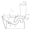
まず、図1は本実施形態の水洗便器の断面図である。図1に示すように、符号1は水洗便器を示し、この水洗便器1の上部の前方側には、ボウル部2が形成され、後方側の上部には導水路4が、導水路4の下方にはボウル部2と連通する排水トラップ管路6が、それぞれ形成されている。
Hereinafter, a flush toilet according to an embodiment of the present invention will be described with reference to the accompanying drawings.
First, FIG. 1 is a sectional view of a flush toilet of this embodiment. As shown in FIG. 1,
水洗便器1のボウル部2の上縁部にはオーバーハング形状のリム8が形成され、このリム8に導水路4から洗浄水が供給される1つ又は2つのリム吐水口10が形成され、洗浄水が旋回しながら下降してボウル部2を洗浄できるようになっている。また、ボウル部2の中心下部には、導水路4から洗浄水が供給されるジェット吐水口12が形成され、このジェット吐水口12から洗浄水が排水トラップ管路6に向けて吐水され、サイホンを短時間で発生されるようになっている。
An overhang-
水洗便器1の導水路4の上方には、洗浄水を貯留するロータンク14が設けられている。このロータンク14の底面14aには、水洗便器1の導水路4と連通する連通口14bが形成されている。
Above the water conduit 4 of the
つぎに、図2及び図3により、ロータンク14の詳細について説明する。図2はロータンクの内部を示す正面断面図であり、図3はロータンクの平面図である。
図2に示すように、ロータンク14は、ロータンク14の外枠を形成するロータンク本体14cと、このロータンク本体14cの上に着脱自在に固定され且つその上面に手洗い鉢14dを形成する蓋14eとを備えている。
ロータンク本体14cは、洗浄水が貯留される内タンク14fを含み、この内タンク14fには、排水弁16、オーバーフロー管18、給水管20、ボールタップ22、及び、フロート24が設けられている。ロータンク14の上方に設けられた手洗い鉢14dを形成する蓋14eには給水接続機能はなく、仮に蓋14eを取り外したり、再度取り付けたりする事態になっても、その接続作業の良否によって漏水事故が発生することがないようになっている。
Next, the details of the
As shown in FIG. 2, the
The low tank
具体的には、排水弁16は、大洗浄用の弁体16aと小洗浄用の弁体16bからなり、両弁体16a,16bは、ロータンク14の底面14aの連通口14bの部分に設けられている。また、各弁体16a,16bは、操作レバー26に接続された玉鎖28a,28bにそれぞれ接続されており、操作レバー26を操作して大洗浄又は小洗浄を切り替えることにより、大洗浄用の弁体16a又は小洗浄用の弁体16bの開閉操作が行われるようになっている。
Specifically, the
この排水弁16は、閉操作により洗浄水をロータンク本体14cの内タンク14f内に貯水し、開操作により、ロータンク本体14cの内タンク14f内の洗浄水を水洗便器1の導水路4を経由して、リム吐水口10及びジェット吐水口12に導くようになっている。
The
また、オーバーフロー管18は、その上端に開口18aが形成されその下端が排水弁16の弁座16cに連通するように設けられている。このオーバーフロー管18により、洗浄水の水位が万一上昇しても、開口18aから、洗浄水がオーバーフローし、排水弁16の弁座16aを経由して、さらに、水洗便器1の導水路4を経て、リム吐水口10とジェット吐水口12から、ボウル部2内に排出されるようになっている。
The
さらに、給水管20は、ロータンク14の底面14aに取り付けられ、外部の水道等の給水源(図示せず)に接続され、洗浄水をロータンク本体14cの内タンク14f内に供給するようになっている。
給水管20の先端部には、ロータンク本体14cの内タンク14f内に洗浄水を給水する給水手段としてボールタップ22が設けられている。このボールタップ22には、アーム30が取り付けられており、さらに、アーム30の右端部にはフロート24が取り付けられている。フロート24が内タンク14f内の洗浄水の水位の変動に伴って上下動することにより、ボールタップ22内の給水バルブ(図示せず)が開閉し、給水管20から内タンク14f内への洗浄水の吐水及び止水が切り替えられるようになっている。
Further, the
A
ボールタップ22には、給水管20とは別に手洗い給水管32が分岐して設けられている。この手洗い給水管32は、ボールタップ22から分岐してロータンク本体14cの側面に隣接して設けられた始端部32aから手洗い鉢14dの高さを超える中間部32bまで上方に起立して延びている。
また、手洗い給水管32は、中間部32bからその終端部である吐水口32cにかけて、この吐水口32cが手洗い鉢14dの上方に位置するように、手洗い鉢14dの排水孔14gが形成される手洗い鉢14dの中心方向に向かって延びており、蓋14eの上面全体が手洗い鉢14dとして利用できるようにロータンク本体14cの側面から手洗い鉢14dを迂回して配置されている。
In addition to the
Further, the hand-washing
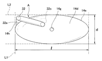
さらに、図3に示すように、手洗い鉢14dの外周は楕円形状を有している。この楕円形状の手洗い鉢14dの最大横幅寸法lと最大奥行き寸法dを画定する寸法線をそれぞれL1、L2とすると、手洗い給水管32の始端部32aから中間部32bの部分は、これら寸法線L1、L2とロータンク本体14cの側面14hによって囲まれる領域A内に配置されている。
すなわち、手洗い給水管32の始端部32aから中間部32bの部分は、手洗い鉢14の横幅寸法と奥行き寸法との最大範囲内でロータンク本体14cから起立している。
手洗い給水管32より手洗い鉢14d内に吐水された水は排水孔14gよりロータンク本体14cの内タンク14f内に排水されるようになっている。
Furthermore, as shown in FIG. 3, the outer periphery of the hand-
That is, the portion from the
Water discharged from the hand-washing
上述した本実施形態の水洗便器1によれば、蓋14eの全面を手洗い鉢14dとして利用できるため、手洗い行為もしやすい。図示しない開放された便座や便ふたを回避して使用者は手を手洗い鉢14d上にアプローチすることになるが、そのアプローチ方向は手洗い給水管32と干渉することは無く、手洗い動作が行いやすいことになる。また、手洗い給水管32がロータンク本体14cの側面14hから手洗い鉢14dを迂回して配置されているため、メンテナンスの際には蓋14eの開閉に気を使う必要がない。
また、本実施形態の水洗便器1によれば、手洗い鉢14dの外周が楕円形状を有し、手洗い給水管32が、楕円形状の手洗い鉢14dの横幅寸法lと奥行き寸法dとの最大範囲内でロータンク本体14cから起立しているため、トイレ空間の有効スペースを効果的に利用することができる。したがって、手洗い鉢14dのスペースを確保しつつ、トイレ空間内の水洗便器1の前出寸法を極力抑えた手洗い鉢付のロータンク構造を備えた水洗便器を提供することができる。さらに、水洗便器1と手洗い給水管32との一体感を損なうことなく、意匠性に優れたものとなる。
According to the
Moreover, according to the
1 水洗便器
14 ロータンク
14c ロータンク本体
14d 手洗い鉢
14e 蓋
14f 内タンク
20 給水管
22 ボールタップ
32 手洗い給水管
DESCRIPTION OF
Claims (2)
洗浄水を貯留するロータンク本体と、
このロータンク本体の上に着脱自在に固定され且つその上面全体に手洗い鉢を形成する蓋と、
上記ロータンク本体へ洗浄水を給水する給水手段と、
この給水手段から分岐し且つ上記手洗い鉢の上方に吐水口を位置させるように延びる手洗い給水管と、を有し、
上記手洗い給水管は、上記ロータンク本体側面から上記手洗い鉢を迂回して配置されると共に、上記手洗い鉢の横幅寸法と奥行き寸法との最大範囲内で上記ロータンク本体から起立していることを特徴とする水洗便器。 A flush toilet that is washed with wash water,
A low tank body for storing washing water;
A lid that is detachably fixed on the low tank body and forms a hand-washing bowl over the entire upper surface;
Water supply means for supplying cleaning water to the low tank body;
A hand wash water supply pipe branched from the water supply means and extending so as to position the water outlet above the hand wash bowl,
The hand-washing water supply pipe is arranged so as to bypass the hand-washing bowl from the side of the low-tank main body, and stands up from the low-tank body within a maximum range of a width dimension and a depth dimension of the hand-washing bowl. Flush toilet.
Priority Applications (1)
| Application Number | Priority Date | Filing Date | Title |
|---|---|---|---|
| JP2008087692A JP5382603B2 (en) | 2008-03-28 | 2008-03-28 | Flush toilet |
Applications Claiming Priority (1)
| Application Number | Priority Date | Filing Date | Title |
|---|---|---|---|
| JP2008087692A JP5382603B2 (en) | 2008-03-28 | 2008-03-28 | Flush toilet |
Publications (3)
| Publication Number | Publication Date |
|---|---|
| JP2009243051A JP2009243051A (en) | 2009-10-22 |
| JP2009243051A5 JP2009243051A5 (en) | 2011-04-28 |
| JP5382603B2 true JP5382603B2 (en) | 2014-01-08 |
Family
ID=41305262
Family Applications (1)
| Application Number | Title | Priority Date | Filing Date |
|---|---|---|---|
| JP2008087692A Expired - Fee Related JP5382603B2 (en) | 2008-03-28 | 2008-03-28 | Flush toilet |
Country Status (1)
| Country | Link |
|---|---|
| JP (1) | JP5382603B2 (en) |
Family Cites Families (3)
| Publication number | Priority date | Publication date | Assignee | Title |
|---|---|---|---|---|
| JPS5096347U (en) * | 1973-12-29 | 1975-08-12 | ||
| JPS586874U (en) * | 1981-07-02 | 1983-01-17 | イナ・イホ−株式会社 | Toilet cleaning tank with hand basin |
| JPH10266298A (en) * | 1997-03-28 | 1998-10-06 | Matsushita Electric Works Ltd | Low tank with towel hanger |
-
2008
- 2008-03-28 JP JP2008087692A patent/JP5382603B2/en not_active Expired - Fee Related
Also Published As
| Publication number | Publication date |
|---|---|
| JP2009243051A (en) | 2009-10-22 |
Similar Documents
| Publication | Publication Date | Title |
|---|---|---|
| EP1273726B1 (en) | Western style water closet | |
| US8826934B2 (en) | Apparatus for preventing backflow of fill valve in water toilet | |
| JP2012207503A (en) | Water closet | |
| JP2024028564A (en) | flush toilet | |
| JP2018105048A (en) | Flush toilet bowl | |
| JP2013104271A (en) | Drain valve device, washing water tank device with the drain valve device, and water closet with the washing water tank device | |
| JP5382603B2 (en) | Flush toilet | |
| JP5928978B2 (en) | Toilet flush water tank | |
| KR100225965B1 (en) | A toilet bowl using recycling water | |
| JP2010236201A (en) | Flush toilet bowl | |
| JP2010071055A (en) | Toilet stool washing water feeding device | |
| JP4757037B2 (en) | Drain trap | |
| JP3879743B2 (en) | Drain trap | |
| JP6666578B2 (en) | Drain valve device, flush water tank device equipped with this flush valve device, and flush toilet equipped with this flush water tank device | |
| JP5293048B2 (en) | Washbasin | |
| JP6880450B2 (en) | Washing water tank device | |
| JP2611602B2 (en) | Tank assembly for Western style toilet | |
| KR200262721Y1 (en) | Save water type toilet stool bowl | |
| JP5327707B2 (en) | Toilet flush water tank | |
| KR200341887Y1 (en) | Bibcock for washbasin | |
| JP2009072533A (en) | Bathtub | |
| JP6617877B2 (en) | Flush toilet | |
| KR200206146Y1 (en) | Water saving device of a chamber pot | |
| JP2902597B2 (en) | Toilet water supply structure | |
| KR200331938Y1 (en) | water saving closet |
Legal Events
| Date | Code | Title | Description |
|---|---|---|---|
| A521 | Written amendment |
Free format text: JAPANESE INTERMEDIATE CODE: A523 Effective date: 20110311 |
|
| A621 | Written request for application examination |
Free format text: JAPANESE INTERMEDIATE CODE: A621 Effective date: 20110311 |
|
| A977 | Report on retrieval |
Free format text: JAPANESE INTERMEDIATE CODE: A971007 Effective date: 20120927 |
|
| A131 | Notification of reasons for refusal |
Free format text: JAPANESE INTERMEDIATE CODE: A131 Effective date: 20121009 |
|
| A521 | Written amendment |
Free format text: JAPANESE INTERMEDIATE CODE: A523 Effective date: 20121210 |
|
| TRDD | Decision of grant or rejection written | ||
| A01 | Written decision to grant a patent or to grant a registration (utility model) |
Free format text: JAPANESE INTERMEDIATE CODE: A01 Effective date: 20130909 |
|
| A61 | First payment of annual fees (during grant procedure) |
Free format text: JAPANESE INTERMEDIATE CODE: A61 Effective date: 20130922 |
|
| R150 | Certificate of patent or registration of utility model |
Ref document number: 5382603 Country of ref document: JP Free format text: JAPANESE INTERMEDIATE CODE: R150 Free format text: JAPANESE INTERMEDIATE CODE: R150 |
|
| LAPS | Cancellation because of no payment of annual fees |