JP5380475B2 - Sealed container - Google Patents
Sealed container Download PDFInfo
- Publication number
- JP5380475B2 JP5380475B2 JP2011018816A JP2011018816A JP5380475B2 JP 5380475 B2 JP5380475 B2 JP 5380475B2 JP 2011018816 A JP2011018816 A JP 2011018816A JP 2011018816 A JP2011018816 A JP 2011018816A JP 5380475 B2 JP5380475 B2 JP 5380475B2
- Authority
- JP
- Japan
- Prior art keywords
- discharge member
- container body
- sealed container
- container
- contents
- Prior art date
- Legal status (The legal status is an assumption and is not a legal conclusion. Google has not performed a legal analysis and makes no representation as to the accuracy of the status listed.)
- Expired - Fee Related
Links
Images


Description
本発明は密封容器に関する。 The present invention relates to a sealed container.
従来より市販されている弁当などには、醤油やマヨネーズ、ドレッシングなどを小さい袋に充填したものが付いていることがある。そのような袋は、図5に示すように、ポリエチレンやポリプロピレンなどの合成樹脂製のシート101を2枚重ね、周縁部102を熱
溶着して密封している。そして熱溶着した一部に切れ目103を設けており、使用時に切れ目103から袋100の一部を切断して内容物を取り出す構造になっている。この製品では、切れ目103から切断し、袋100を指で押さえて内容物を取り出すが、袋100を押した状態で切れ目103を切断してしまうと内容物が思わぬ方向に飛び散る場合がある。そのためこのような袋を開封する場合は、周縁部102を摘むなど、できるだけ袋100を押さずに切れ目103を切断する必要がある。
Lunch boxes that have been marketed in the past may have a small bag filled with soy sauce, mayonnaise, or dressing. As shown in FIG. 5 , such a bag has two
また、常温で気化する内容物、あるいは蒸気圧を有する内容物を充填した袋の場合は、袋100を押さない状態で開封しても、切れ目103から内容物が飛び出てくる。そのため、切れ目103を内容物を受ける容器などに向けた上で、慎重に開封したり、切れ目103を上に向けて少し開封し、一旦ガスだけを放出し、その後、大きく開封するなどの手順が必要である。
Further, in the case of a bag filled with a content that vaporizes at room temperature or a content having vapor pressure, the content pops out from the
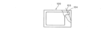
他方、図6に示すような、袋100の角部分などに先端が閉じた細い通路104を設け、その通路の途中を切断させるように切れ目103を設けたものもある。このものは想像線のように切断した後、内容物は通路104の方向に飛び出す。そのため容器などに受けやすい利点がある。しかし切断した直後に切り口から内容物が飛び出す点では前述の場合と同じであり、周囲を汚すおそれは充分には解消されていない。
On the other hand, as shown in FIG. 6, there is a type in which a
本発明は誤って指で押圧した状態で開封しても、さらに内容物が蒸気圧を有するものであっても、開封直後に噴出せず、そのため周囲に飛び散る危険性が少ない密封容器を提供することを技術課題としている。 The present invention provides a sealed container that does not spout immediately after opening even if it is opened in a state where it is accidentally pressed with a finger, and even if the contents have vapor pressure, and therefore has a low risk of splashing around. This is a technical issue.
本発明の密封容器は、重ね合わせて周縁部を溶着した2枚のシートからなる袋状の容器本体と、その容器本体に連結される排出部材とからなり、前記容器本体は、前記2枚のシートの間に介在されて周縁部で一緒に熱溶着されたシートからなり、容器本体の内部を複数室に仕切る隔壁を備えており、前記排出部材が、先端部が容器本体の外部に開口しており、排出部材の先端部から離れた位置に、常時は容器本体の内部と連通せず、外力により開放されて連通する閉鎖部を有することを特徴としている。
The sealed container of the present invention comprises a bag-like container body composed of two sheets that are overlapped and welded at the periphery, and a discharge member connected to the container body. It is composed of a sheet interposed between the sheets and heat-welded together at the periphery, and has a partition wall that divides the interior of the container body into a plurality of chambers, and the discharge member has a leading end that opens to the outside of the container body. It is characterized in that it has a closed portion that is not communicated with the inside of the container body at a position apart from the distal end portion of the discharge member but is opened and communicated by an external force .
このような密封容器の排出部材がそれぞれの室内の液体を別々に吐出できるように分割されているものが好ましい。
さらに、前記容器本体の内部が2室に仕切られているものが好ましい。
また、前記隔壁を構成するシートが、排出部材の側面に熱溶着されており、容器本体の内部が排出部材によって少なくとも2室に仕切られており、閉鎖部を開放するときに各室が排出部材と連通するように構成されているものが好ましい。
本発明の密封容器であって、前記2室にそれぞれ2液タイプの染毛剤または接着剤が充填されるものが好ましい。
Which discharge member of such a sealed container is divided so as to be discharged separately each liquid chamber is preferred.
Furthermore, it is preferable that the inside of the container body is partitioned into two chambers.
Further, the sheet constituting the partition wall is thermally welded to the side surface of the discharge member, the interior of the container body is partitioned into at least two chambers by the discharge member, and each chamber is opened when the closing portion is opened. What is comprised so that it may communicate with is preferable.
The sealed container of the present invention is preferably one in which the two chambers are filled with a two-component hair dye or an adhesive, respectively.
本発明の密封容器は、重ね合わせて周縁部を溶着した2枚のシートからなる袋状の容器本体と、その容器本体に連結される排出部材とからなり、前記容器本体は、前記2枚のシートの間に介在されて周縁部で一緒に熱溶着されたシートからなり、容器本体の内部を複数室に仕切る隔壁を備えており、前記排出部材が、先端部が容器本体の外部に開口しており、排出部材の先端部から離れた位置に、常時は容器本体の内部と連通せず、外力により開放されて連通する閉鎖部を有するため、それぞれの室に別の種類の内容物を混合しないように充填しておくことができる。そのため、2液タイプの染毛剤や、2液タイプの接着剤など、充填時には分離して保管しておき、使用時に始めて混合する2液を充填するために利用しうる。また、排出部材の内部が先端部の開口で外部と連通していても、容器本体の内部は密封されている。そして閉鎖部を外力で連通させると、内容物は、直接外部に噴出せず、まず排出部材内に入る。そして内容物は排出部材にある程度溜まった後、排出部材の開口から外部に出てくる。すなわちこの密封容器では排出部材がいわばバッファとして機能し、閉鎖部を開封してから排出部材の先端から内容物が吐出するまでは若干の経過時間があるので、いきなり排出口より飛び出したりすることはない。そのため、使用者は内容物の吐出に備えて開口を受け皿などに向けることができる。
The sealed container of the present invention comprises a bag-like container body composed of two sheets that are overlapped and welded at the periphery, and a discharge member connected to the container body. It is composed of a sheet interposed between the sheets and heat-welded together at the periphery, and has a partition wall that divides the interior of the container body into a plurality of chambers, and the discharge member has a leading end that opens to the outside of the container body. Because it has a closed part that is not communicated with the inside of the container body at a position away from the tip of the discharge member at all times but is opened and communicated by external force, different types of contents are mixed in each chamber. It can be filled so that it does not. Therefore, it can be used for filling two liquids such as a two liquid type hair dye and a two liquid type adhesive which are separated and stored at the time of filling and mixed for the first time at the time of use. Even if the inside of the discharge member communicates with the outside through the opening of the tip, the inside of the container body is sealed. When the closed portion is communicated with an external force, the contents are not directly ejected to the outside, but first enter the discharge member. Then, after the contents are accumulated in the discharge member to some extent, the contents come out from the opening of the discharge member. That is, in this sealed container, the discharge member functions as a buffer, and since there is a slight elapsed time from opening the closing part to discharging the contents from the tip of the discharge member, it suddenly jumps out of the discharge port. Absent. Therefore, the user can point the opening to the receiving tray in preparation for discharging the contents.
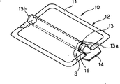
図1に示す参考の密封容器10は、重ね合わせて周縁部11を熱溶着した2枚のシートからなる袋状の容器本体12と、その容器本体内に内装された筒状の排出部材13とから構成されている。本発明の密封容器は、容器本体12の代わりに図4a、bの容器本体が用いられる。
Tightly sealed
前記容器本体12を構成するシートは、ポリエチレン、ポリプロピレン、エチレン−酢酸ビニル共重合体、ポリエチレンテレフタレート、ナイロンなど、従来公知の密封容器に使用される熱溶着可能な合成樹脂製の可撓性のシートが用いられる。なお上記の熱溶着性を有する内層フィルムに、ガスバリア性を有するアルミニウム箔などの金属箔を積層したり、アルミニウムなどの金属やシリカ、炭素などを蒸着した外層フィルムを積層するなど、異なる種類の材質の2枚以上のフィルムを積層したラミネートシートを用いてもよい。さらに容器本体12を構成する2枚のシートは通常は同じ種類の材質のシートであるが、異なる種類のシートを用いてもよい。また、互いに熱溶着しない2枚のシートを用い、それらの間に両方に対して熱溶着可能なフィルムを介在させてもよく、さらに接着剤をコーティングして接着することもできる。
The sheet constituting the
前記排出部材13は、先端部13bが開放され、基端部13aが閉じている筒状の部材であり、ポリエチレン、ポリプロピレン、ポリエチレンテレフタレートなどの合成樹脂で構成される。なお、金属やガラスなど、他の材料でもよい。排出部材13は内容物の内圧によって中空部が押しつぶされない程度の固さを有するものが好ましい。ただし可撓性を有するもの、柔軟なものであってもよい。排出部材13の基端部13aには、平板状の摘み片14が一体に設けられている。摘み片14の根元部14aは、この形態では排出部材13の蓋になっている。排出部材13の外周で、基端部13aからいくらか先端側に寄った位置には、折り曲げあるいは捻りによって容易に破断させることができ、しかも破断される前は排出部材13の内部と外部を気密・液密状態を維持する環状の溝(弱め線)15が形成されている。弱め線15は請求項1の閉鎖部であり、容器本体12の収納部S内に配置されている。なお図1では排出部材13の断面形状は円形であるが、楕円状であってもよく、角筒状であってもよい。
The
排出部材13の基端部13aの近辺および先端部13bは図2aおよび図2bに示すように、それぞれ2枚のシートの間に挟まれ、収納部Sと外部との気密性および液密性を維持するように熱溶着または接着されている。なお摘み片14を挟むように熱溶着してもよく、そのほうが排出部材13とシートとの密着性が強くなって操作がし易くなる。さらに摘み片14を捻ったときにシートと排出部材13の熱溶着が剥がれにくい。
As shown in FIGS. 2a and 2b, the vicinity of the
このように構成される密封容器10に内容物を充填するには、たとえば容器本体12の周縁部11の一辺、たとえば図2の下部側を熱溶着せずに開放しておき、その開放部から内容物を充填し、その後、熱溶着して密封する。内容物は通常はドレッシングや化粧水、シャンプー、リンスなどの液体、マヨネーズなどのクリーム状のものなど、従来、袋に充填していたものをいずれも採用しうる。
In order to fill the sealed
内容物を充填し、密封した密封容器10は、図2bに示すように、収納部Sが外部から遮断されている。この密封容器10を開封するには、たとえば片方の手で容器本体12の上から排出部材13の先端部13bないし中央部を摘み、他方の手で摘み片14を摘んで捻る。そうすると図2の弱め線15の位置で排出部材13が破断され、基端部13a側と先端部13b側とに分離する。なお、容器本体12は可撓性を有するので、摘み片14を捻るときにそれほど邪魔にならない。そして弱め線15で完全に分離した後も、摘み片14と基端部13aは容器本体12に挟まれているので、抜け落ちることはなく、容器本体12に付着されている。しかし一旦分離した弱め線15の部位はシール作用が奏されないので、内容物は、矢印Pで示すように、排出部材13の破断によって生じた開口部16から排出部材13の内部に入る。
As shown in FIG. 2 b, the sealed
しかし排出部材13の内部はそれまで空洞であったため、その空洞内に内容物が入っても直ちに先端部13bの開口から噴出することはない。そしていくらか時間が経過してから、開口から内容物が流れ出る。そのため使用者は摘み片14を捻るときはその作業に集中することができ、弱め線15で排出部材13を破断した後、内容物を開口からたとえば受け皿などに流し出すことに集中できる。このように破断した直後でも、内容物が一旦排出部材13内に入っていわばバッファ作用が奏されるので、内圧がある場合でも、破断とともに噴出するおそれがない。
However, since the inside of the
したがって内容物としては、水、アルコールなどの常温で蒸気圧が低い成分のほか、ブタン、ペンタン、ヘキサンなど、常温で蒸気圧を有するもの、あるいは混合することにより蒸気圧を発生する成分を含んでいてもよい。蒸気圧を有する成分を含む場合、該成分や、該成分と共に配合される成分、さらに容器本体を冷却してから充填するのが好ましい。そのような蒸気圧を有するものでも、開封後に噴出することがない。また、蒸気圧によって生ずる内圧を有効に利用し、内容物の圧力で噴出させるようにしてもよい。前記内容物の具体例としては、水、低級アルコール、多価アルコール、シリコーンオイル、炭化水素油、エステルオイルなどに、トリートメント剤、セット剤、艶消し剤、染毛剤、脱毛剤などの頭髪用、皮膚軟化剤、保湿剤、角質除去剤、殺菌剤、消毒剤、クレンジング剤、シェービング剤、制汗剤、消炎鎮痛剤、害虫忌避剤、化粧水、コロン、消臭剤、美白剤などの人体用などの有効成分を溶解もしくは分散させたもの、さらにこれらに前記蒸気圧を有する成分を配合したものがあげられる。また、吐出形態(ミスト、泡、クリーム、ゲル)に応じて、界面活性剤や増粘剤などを配合することができる。 Therefore, the contents include components having a low vapor pressure at normal temperature such as water and alcohol, but also components having a vapor pressure at normal temperature such as butane, pentane and hexane, or components that generate a vapor pressure when mixed. May be. When a component having a vapor pressure is included, it is preferable that the component, a component blended together with the component, and the container body are cooled before filling. Even those having such a vapor pressure are not ejected after opening. In addition, the internal pressure generated by the vapor pressure may be effectively used and ejected with the pressure of the contents. Specific examples of the contents include water, lower alcohols, polyhydric alcohols, silicone oils, hydrocarbon oils, ester oils, hair treatment agents, set agents, matting agents, hair dyes, hair removal agents, etc. , Emollients, moisturizers, exfoliants, bactericides, disinfectants, cleansing agents, shaving agents, antiperspirants, antiphlogistics, pest repellents, lotions, colons, deodorants, whitening agents, etc. For example, those obtained by dissolving or dispersing active ingredients such as those for use, and those obtained by blending these with ingredients having the above-mentioned vapor pressure. Moreover, a surfactant, a thickener, etc. can be mix | blended according to a discharge form (mist, foam, cream, gel).
図1の密封容器10では、排出部材13の基端部13aの近辺に形成した環状溝15によって閉鎖部が形成されているが、折り曲げによって破断させる場合は、排出部材13の上面側あるいは下面側に線状の溝を形成してもよく、両方に形成してもよい。また、側面側に弱め線を形成してもよい。さらに図3aに示すように、排出部材13を基端部側21と先端部側22とをあらかじめ分離しておき、両者の端面21a、22a同士を当接させた上で、その隙間をアルミニウム箔などの容易に破断しうるシート23で密封するようにしてもよい。
In the sealed
図3bに示す閉鎖部25は、排出部材13の基端部13aを開口させ、その開口部26にプラグ27を液密状態で詰めている。そしてプラグ27の端部に摘み28を一体に設けている。このものは摘み28を摘んでプラグ27を排出部材13の基端部13aから抜き取ると、開口部26によって排出部材13の内部と容器本体12の収納部Sとが連通する。
The closing
図3cに示す閉鎖部30では、排出部材13の基端部13aを円筒状に構成し、その内部に円筒状のプラグ31を回動自在に、且つ、液密状態で嵌合させている。そして排出部材13の基端部13aおよびプラグ31には、それぞれ特定の回転位置で連通する窓32、33が形成されている。そして通常はプラグ31は、窓32、33同士が連通しない位置に係止させておき、使用時にプラグ31を回動させて窓32、33同士を連通させる。
In the
図1の密封容器10は、閉鎖部を連通させるときの外力を加える手段として、摘み片や摘みを用いており、それらは容器本体12の外部に突出させている。そのため操作しやすい。しかし容器本体12を構成するシートが、その上から摘み片を操作できるほど柔軟なものであれば、摘み片などを容器本体12の内部に入れておくこともできる。
The sealed
また排出部材13の先端部13bもとくに限定はなく、容器本体13から突出させてもよい。また、内径が排出部材13の空洞の内径よりも細いノズルを装着してもよい。さらにこれにチューブを連結するようにしてもよい。
Further, the
図4a、bは容器本体の内部を隔壁で仕切った密封容器の実施形態を示している。図4aの密封容器34では、容器本体を構成する2枚のシート35の間に同様なシートからなる隔壁36が介在され、周縁部11で一緒に熱溶着されている。また隔壁36内側の端縁は、排出部材13の側面に熱溶着されている。このものは隔壁36で容器本体12の内部が2室に分割されているので、それぞれの室37、38に別の種類の内容物を混合しないように充填しておくことができる。そのため、2液タイプの染毛剤や、2液タイプの接着剤など、充填時には分離して保管しておき、使用時に初めて混合する2液を充填するために利用しうる。前述した混合により蒸気圧を発生するタイプの内容物も、このような密封容器34に充填するのが好ましい。前述のように、2液を排出部材内で混合し、この状態で出してもよいが、排出部材を分割し、2液を別々に吐出してもよい。
4a and 4b show an embodiment of a sealed container in which the inside of the container body is partitioned by a partition wall. In the sealed
このような隔壁36を設ける場合は、排出部材13が安定し、容器全体の形状保持性も高まる。また、このような利点があるため、同一の内容物を充填してもよい。このものに図1の閉鎖部を設ける場合は、摘み片14を捻って開封することもできるが、隔壁36が設けられている側と反対側が開くように、排出部材13を折り曲げるほうが容易に弱め線15を破断しうる。それにより開放された排出部材13の開口は、いずれの室37、38とも連通し、排出部材13の内部で2種類の内容物が混合され、その後、先端の開口から吐出される。なお隔壁36を1枚のシートとし、その中央部を排出部材13の片面に熱溶着してもよいが、その場合は弱め線に対応する部位に窓をあけるなどにより、閉鎖部の開封後における収納部Sと排出部材13の連通を確保する。
When such a
図4bに示す密封容器40は、収納部を左右方向に仕切る隔壁36のほか、上下方向に仕切る隔壁41を有し、全体として4つの室に分割している。そのため4種類の内容物を充填しておくことができる。なお、3室あるいは5室以上に分割することもできる。
The sealed
10 密封容器
11 周縁部
12 容器本体
13 排出部材
S 収納部
13a 基端部
13b 先端部
14 摘み片
15 弱め線
21 基端部側
22 先端部側
23 シート
25 閉鎖部
26 開口部
27 プラグ
30 閉鎖部
31 プラグ
32、33 窓
34 密封容器
35 シート
36 隔壁
37、38 室
40 密封容器
41 隔壁
100 袋
101 シート
102 周縁部
103 切れ目
104 通路
DESCRIPTION OF
100 bags
101 sheets
102 peripheral edge
103 breaks
104 passages
Claims (5)
その容器本体に連結される排出部材とからなり、
前記容器本体は、前記2枚のシートの間に介在されて周縁部で一緒に熱溶着されたシートからなり、容器本体の内部を複数室に仕切る隔壁を備えており、
前記排出部材が、先端部が容器本体の外部に開口しており、排出部材の先端部から離れた位置に、常時は容器本体の内部と連通せず、外力により開放されて連通する閉鎖部を有する、密封容器。 A bag-like container body composed of two sheets that are overlapped and welded at the periphery;
It consists of a discharge member connected to the container body,
The container body is composed of a sheet interposed between the two sheets and thermally welded together at the periphery, and includes a partition that partitions the interior of the container body into a plurality of chambers ,
The discharge member has a closed end that is open to the outside of the container body and is not always communicated with the interior of the container body at a position away from the tip of the discharge member, and is open and communicated by an external force. Having a sealed container.
請求項1記載の密封容器。 The discharge member is divided so that the liquid in each chamber can be discharged separately.
The sealed container according to claim 1.
容器本体の内部が排出部材によって少なくとも2室に仕切られており、閉鎖部を開放するときに各室が排出部材と連通するように構成されている、The interior of the container body is partitioned into at least two chambers by a discharge member, and each chamber is configured to communicate with the discharge member when the closing portion is opened.
請求項1記載の密封容器。The sealed container according to claim 1.
Priority Applications (1)
| Application Number | Priority Date | Filing Date | Title |
|---|---|---|---|
| JP2011018816A JP5380475B2 (en) | 2011-01-31 | 2011-01-31 | Sealed container |
Applications Claiming Priority (1)
| Application Number | Priority Date | Filing Date | Title |
|---|---|---|---|
| JP2011018816A JP5380475B2 (en) | 2011-01-31 | 2011-01-31 | Sealed container |
Related Parent Applications (1)
| Application Number | Title | Priority Date | Filing Date |
|---|---|---|---|
| JP2001120104A Division JP4911832B2 (en) | 2001-04-18 | 2001-04-18 | Sealed container |
Publications (2)
| Publication Number | Publication Date |
|---|---|
| JP2011116460A JP2011116460A (en) | 2011-06-16 |
| JP5380475B2 true JP5380475B2 (en) | 2014-01-08 |
Family
ID=44282272
Family Applications (1)
| Application Number | Title | Priority Date | Filing Date |
|---|---|---|---|
| JP2011018816A Expired - Fee Related JP5380475B2 (en) | 2011-01-31 | 2011-01-31 | Sealed container |
Country Status (1)
| Country | Link |
|---|---|
| JP (1) | JP5380475B2 (en) |
Families Citing this family (1)
| Publication number | Priority date | Publication date | Assignee | Title |
|---|---|---|---|---|
| JP2022001496A (en) * | 2020-06-19 | 2022-01-06 | 小林製薬株式会社 | container |
Family Cites Families (5)
| Publication number | Priority date | Publication date | Assignee | Title |
|---|---|---|---|---|
| JPS5924947B2 (en) * | 1981-07-30 | 1984-06-13 | 四郎 斉藤 | package |
| JPS61193042U (en) * | 1985-05-23 | 1986-12-01 | ||
| JPH05294350A (en) * | 1992-04-10 | 1993-11-09 | Toyo Bussan Kk | Disposable container |
| JPH06319782A (en) * | 1993-05-10 | 1994-11-22 | Material Eng Tech Lab Inc | Medical container |
| JP2000007027A (en) * | 1998-06-24 | 2000-01-11 | Nissho Corp | Liquid substance storage container |
-
2011
- 2011-01-31 JP JP2011018816A patent/JP5380475B2/en not_active Expired - Fee Related
Also Published As
| Publication number | Publication date |
|---|---|
| JP2011116460A (en) | 2011-06-16 |
Similar Documents
| Publication | Publication Date | Title |
|---|---|---|
| EP2935039B1 (en) | Squeezable dispensing package and method of making the same | |
| US20060255068A1 (en) | Flexible film package with integral dosing pump | |
| CN102292270B (en) | A dispensing container | |
| CA2841853C (en) | Sanitary dispensing package | |
| RU2459753C2 (en) | Dispenser and method of its making | |
| US20050072442A1 (en) | Self-contained hair-coloring system for touch-up, highlighting and less than full treatment applications | |
| JP2008543683A (en) | Multi-chamber blister package for storing and administering flowable substances | |
| IT9022563A1 (en) | FLEXIBLE LAMINATE CONTAINER WITH OPENING AND CLOSING INSERT. | |
| AU2010250997A1 (en) | Non-resealable thermoformed packaging for liquid or pasty substances | |
| WO2013156808A1 (en) | Reusable or one time use multi-compartment mixing and dispensing applicator tube or special spouted pouch with a sliding clamp | |
| KR20100103644A (en) | Pour channel with cohesive closure valve and locking bubble | |
| CN104703889A (en) | Single use dispenser package | |
| JP2004059141A (en) | Plastic made refill container | |
| KR20190033314A (en) | Pouch for easy to mix two contents | |
| JPH11263354A (en) | Packaging bag | |
| JP5380475B2 (en) | Sealed container | |
| JP5380517B2 (en) | Sealed container | |
| JP4911832B2 (en) | Sealed container | |
| JP4967289B2 (en) | Pouch container with spout | |
| JP6044897B2 (en) | Drip-type packaging structure and drip-type packaging | |
| JP2009202879A (en) | Pouch | |
| JP4520218B2 (en) | Multi-chamber container and method for mixing and discharging contents of the container | |
| JP6921393B2 (en) | Fluid discharge tool | |
| JP5169481B2 (en) | container | |
| JP2010241484A (en) | Double-folded packaging container |
Legal Events
| Date | Code | Title | Description |
|---|---|---|---|
| A131 | Notification of reasons for refusal |
Free format text: JAPANESE INTERMEDIATE CODE: A131 Effective date: 20121204 |
|
| A521 | Written amendment |
Free format text: JAPANESE INTERMEDIATE CODE: A523 Effective date: 20130204 |
|
| TRDD | Decision of grant or rejection written | ||
| A01 | Written decision to grant a patent or to grant a registration (utility model) |
Free format text: JAPANESE INTERMEDIATE CODE: A01 Effective date: 20130924 |
|
| A61 | First payment of annual fees (during grant procedure) |
Free format text: JAPANESE INTERMEDIATE CODE: A61 Effective date: 20130930 |
|
| R150 | Certificate of patent or registration of utility model |
Ref document number: 5380475 Country of ref document: JP Free format text: JAPANESE INTERMEDIATE CODE: R150 Free format text: JAPANESE INTERMEDIATE CODE: R150 |
|
| R250 | Receipt of annual fees |
Free format text: JAPANESE INTERMEDIATE CODE: R250 |
|
| R250 | Receipt of annual fees |
Free format text: JAPANESE INTERMEDIATE CODE: R250 |
|
| LAPS | Cancellation because of no payment of annual fees |