JP5378960B2 - Spinning apparatus, nonwoven fabric manufacturing apparatus, nonwoven fabric manufacturing method, and nonwoven fabric - Google Patents
Spinning apparatus, nonwoven fabric manufacturing apparatus, nonwoven fabric manufacturing method, and nonwoven fabric Download PDFInfo
- Publication number
- JP5378960B2 JP5378960B2 JP2009266504A JP2009266504A JP5378960B2 JP 5378960 B2 JP5378960 B2 JP 5378960B2 JP 2009266504 A JP2009266504 A JP 2009266504A JP 2009266504 A JP2009266504 A JP 2009266504A JP 5378960 B2 JP5378960 B2 JP 5378960B2
- Authority
- JP
- Japan
- Prior art keywords
- gas
- liquid
- nonwoven fabric
- spinning
- columnar hollow
- Prior art date
- Legal status (The legal status is an assumption and is not a legal conclusion. Google has not performed a legal analysis and makes no representation as to the accuracy of the status listed.)
- Active
Links
Images


Abstract
Description
本発明は紡糸装置、この紡糸装置を備えた不織布製造装置、前記不織布製造装置を用いる不織布の製造方法、及び前記製造方法により製造した不織布に関する。 The present invention relates to a spinning device, a nonwoven fabric manufacturing apparatus equipped with the spinning device, a nonwoven fabric manufacturing method using the nonwoven fabric manufacturing device, and a nonwoven fabric manufactured by the manufacturing method.
不織布を構成する繊維の繊維径が小さいと、分離性能、液体保持性能、払拭性能、隠蔽性能、絶縁性能、或いは柔軟性など、様々な性能に優れているため、不織布を構成する繊維の繊維径は小さいのが好ましい。このような繊維径の小さい繊維からなる不織布の製造方法として、加熱溶融したポリマーを吐出するとともに、このポリマーに対して加熱ガスを吹き付けることにより引き伸ばして繊維化し、繊維を捕集して不織布とする、いわゆるメルトブロー法が知られている。このメルトブロー法は加熱ガス量が多く、その流速も不安定であることから、ポリマーの引き伸ばしが安定しない。その結果、不織布の繊維径分布が広く、品質が安定しないものであった。 If the fiber diameter of the fibers that make up the nonwoven fabric is small, the fiber diameter of the fibers that make up the nonwoven fabric is excellent because it has excellent performance such as separation performance, liquid retention performance, wiping performance, concealment performance, insulation performance, or flexibility. Is preferably small. As a method of manufacturing a nonwoven fabric composed of fibers having such a small fiber diameter, a heated and melted polymer is discharged and heated to blow the heated gas to form a fiber, and the fiber is collected to obtain a nonwoven fabric. A so-called melt blow method is known. In this melt blow method, the amount of heated gas is large, and the flow rate is also unstable, so that the stretching of the polymer is not stable. As a result, the fiber diameter distribution of the nonwoven fabric was wide and the quality was not stable.
例えば、メルトブロー法に使用できる紡糸装置として、図2に示すような「圧縮ガス流を用いることによってナノファイバの不織マットを形成する装置は、平行な間隔を設けた第1(12)、第2(22)及び第3(32)部材を含み、各々は、供給端部(14,24,34)及び対向出口端部(16,26,36)を有する。第2部材(22)は第1部材(12)に隣接する。第2部材(22)の出口端部(26)は、第1部材(12)の出口端部(16)を越えて延びる。第1(12)及び第2(22)部材は、第1供給スリット(18)を画成する。第3部材(32)は、第1部材(12)の第2部材(22)から反対側で第1部材(12)に隣接して位置する。第1(12)及び第3(32)部材は第1ガススリット(38)を画成し、第1(12)、第2(22)及び第3(32)部材の出口端部(16,26,36)はガスジェット空間(20)を画成する。圧縮ガス流を用いることによってナノファイバの不織マットを形成する方法も含まれる。」が提案されている(特許文献1)。この装置においては、平板状の第1、第2及び第3部材を平行に設けていることから、シート状の加熱溶融したポリマーに対して、加熱した圧縮ガスを作用させることができる。しかしながら、この装置で紡糸しても繊維形状になりにくく、ショット、或いはビーズ(粒子形状の樹脂)を多く含むものとなり、繊維形状にできたとしても太い繊維しか形成できないものであると考えられた。 For example, as a spinning device that can be used in the melt-blowing method, as shown in FIG. 2, “the device for forming a non-woven mat of nanofibers by using a compressed gas flow is the first (12), 2 (22) and third (32) members, each having a supply end (14, 24, 34) and an opposing outlet end (16, 26, 36), the second member (22) being the second. Adjacent to one member (12) The outlet end (26) of the second member (22) extends beyond the outlet end (16) of the first member (12). (22) The member defines a first supply slit (18) and the third member (32) extends from the second member (22) of the first member (12) to the first member (12) on the opposite side. Located adjacent to each other, the first (12) and third (32) members define a first gas slit (38). The exit ends (16, 26, 36) of the first (12), second (22) and third (32) members define a gas jet space (20) by using a compressed gas stream. A method of forming a non-woven mat of fiber is also included "(Patent Document 1). In this apparatus, since the flat plate-like first, second and third members are provided in parallel, the heated compressed gas can be applied to the sheet-like heat-melted polymer. However, even if it is spun by this apparatus, it is difficult to form a fiber shape, and it contains a lot of shots or beads (particle-shaped resin), and even if it can be made into a fiber shape, it is thought that only thick fibers can be formed. .
同様の紡糸装置として、「センターチューブ、センターチューブに同心状かつ離間して位置する第1供給チューブ、第1供給チューブに同心状かつ離間して位置する中間ガスチューブ、中間ガスチューブに同心状かつ離間して位置する第2供給チューブを備え、センターチューブと第1供給チューブは第1環状コラムを形成し、中間ガスチューブと第1供給チューブは第2環状コラムを形成し、中間ガスチューブと第2供給チューブは第3環状コラムを形成し、第1ガスジェット空間がセンターチューブと第1供給チューブの下流側端部に形成され、第2ガスジェット空間が中間ガスチューブと第2供給チューブの下流側端部に形成されるように位置している、圧縮ガスを用いるナノファイバー製造装置。」が提案されている(特許文献2)。この製造装置は環状に吐出された加熱溶融したポリマーに対して、加熱した圧縮ガスを作用させることができる。しかしながら、紡糸が不安定で繊維形状になりにくく、ショット、或いはビーズ(粒子形状の樹脂)を多く含むものであった。
As a similar spinning device, “a center tube, a first supply tube located concentrically and spaced apart from the center tube, an intermediate gas tube located concentrically and spaced apart from the first supply tube, and concentric and separated from the intermediate gas tube. The center tube and the first supply tube form a first annular column, the intermediate gas tube and the first supply tube form a second annular column, and the intermediate gas tube and the first supply tube are spaced apart from each other. 2 supply tubes form a third annular column, a first gas jet space is formed at the downstream end of the center tube and the first supply tube, and a second gas jet space is downstream of the intermediate gas tube and the second supply tube. A nanofiber manufacturing apparatus using compressed gas, which is positioned so as to be formed at the side end portion ”has been proposed (
本発明は上述のような問題点に鑑みてなされたものであり、繊維径が小さく、繊維径の揃った繊維を安定して紡糸できる紡糸装置、この紡糸装置を備えた、繊維径が小さく、繊維径の揃った繊維を含む不織布を製造できる製造装置、この不織布製造装置を用いた、繊維径が小さく、繊維径の揃った繊維を含む不織布の製造方法、及び繊維径が小さく、繊維径の揃った繊維を含む不織布を提供することを目的とする。 The present invention has been made in view of the above problems, a spinning device capable of stably spinning a fiber having a small fiber diameter and a uniform fiber diameter, and the fiber diameter provided with this spinning device is small. Manufacturing apparatus capable of manufacturing non-woven fabric including fibers with uniform fiber diameter, manufacturing method of non-woven fabric including fibers with small fiber diameter and uniform fiber diameter using this non-woven fabric manufacturing apparatus, and small fiber diameter It aims at providing the nonwoven fabric containing the uniform fiber.
本発明の請求項1にかかる発明は、「加熱溶融したポリマーの紡糸液を吐出できる液吐出部を1箇所以上と、前記いずれの液吐出部よりも上流側に位置し、加熱ガスを吐出できるガス吐出部1箇所とを有する、次の条件を満足する紡糸装置。(1)液吐出部を端部とする液用柱状中空部(Hl)を有する、(2)ガス吐出部を端部とするガス用柱状中空部(Hg)を有する、(3)液用柱状中空部(Hl)を延長した液仮想柱状部(Hvl)とガス用柱状中空部(Hg)を延長したガス仮想柱状部(Hvg)とは2mm以下の距離で近接している、(4)液用柱状中空部(Hl)の吐出方向中心軸とガス用柱状中空部(Hg)の吐出方向中心軸とが平行である、(5)ガス用柱状中空部(Hg)の中心軸に対して垂直な平面で切断した時に、ガス用柱状中空部(Hg)の切断面の外周と液用柱状中空部(Hl)の切断面の外周との距離が最も短い直線を、1本だけ引くことができる」である。 According to the first aspect of the present invention, “at least one liquid discharge portion capable of discharging a heated and melted polymer spinning solution is located upstream of any one of the liquid discharge portions, and the heated gas can be discharged. A spinning device having one gas discharge portion and satisfying the following conditions: (1) having a liquid columnar hollow portion (Hl) having the liquid discharge portion as an end, and (2) having the gas discharge portion as an end. (3) The liquid virtual columnar part (Hvl) obtained by extending the liquid columnar hollow part (Hl) and the gas virtual columnar part (Hg) provided by extending the gas columnar hollow part (Hg) Hvg) is close to each other at a distance of 2 mm or less . (4) The discharge column central axis of the liquid columnar hollow portion (Hl) and the discharge column central axis of the gas column hollow portion (Hg) are parallel. (5) When cut along a plane perpendicular to the central axis of the gas columnar hollow (Hg), Columnar hollow for scan distance is the shortest straight line between the outer periphery of the cut surface of the outer peripheral and the liquid columnar hollow for the cut surface (Hl) of (Hg), it is can be drawn only one ".
本発明の請求項2にかかる発明は、「請求項1に記載の紡糸装置に加えて、繊維の捕集体を備えている不織布製造装置。」である。
The invention according to
本発明の請求項3にかかる発明は、「請求項2に記載の不織布製造装置を用いる不織布の製造方法。」である。
Invention of Claim 3 of this invention is "the manufacturing method of the nonwoven fabric using the nonwoven fabric manufacturing apparatus of
本発明の請求項1にかかる発明は、液吐出部から吐出された加熱溶融したポリマーの紡糸液とガス吐出部から吐出された加熱ガスとは近接しており、平行であり、しかも加熱溶融したポリマーの紡糸液には加熱ガスおよび随伴気流による剪断力が1本の直線状に均一に作用するため、繊維径の小さい、繊維径の揃った繊維を紡糸できる。
In the invention according to
本発明の請求項2にかかる発明は、前記紡糸装置に加えて、繊維の捕集体を備えているため、繊維径の小さい、繊維径の揃った繊維を含む不織布を製造することができる。
Since the invention according to
本発明の請求項3にかかる発明は、前記不織布製造装置を用いているため、繊維径の小さい、繊維径の揃った繊維を含む不織布を製造することができる。 Since the invention concerning Claim 3 of this invention uses the said nonwoven fabric manufacturing apparatus, the nonwoven fabric containing the fiber with a small fiber diameter and the uniform fiber diameter can be manufactured.
本発明の請求項4にかかる発明は、前記製造方法により製造した不織布であるため、繊維径の小さい、繊維径の揃った繊維を含む不織布である。 Since the invention concerning Claim 4 of this invention is a nonwoven fabric manufactured with the said manufacturing method, it is a nonwoven fabric containing a fiber with a small fiber diameter and the same fiber diameter.
本発明の紡糸装置について、紡糸装置の先端部を拡大した斜視図である図1(a)、及び図1(a)におけるC平面切断図である図1(b)をもとに説明する。 The spinning device of the present invention will be described with reference to FIG. 1 (a), which is an enlarged perspective view of the tip of the spinning device, and FIG. 1 (b), which is a C plane cut view in FIG. 1 (a).
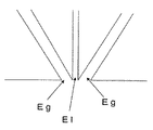
本発明の紡糸装置は加熱溶融したポリマーの紡糸液を吐出できる液吐出部Elを一方の端部に有する液吐出ノズルNl1本と、加熱ガスを吐出できるガス吐出部Egを一方の端部に有するガス吐出ノズルNg1本の外壁面が当接し、ガス吐出ノズルNgのガス吐出部Egが液吐出部Elよりも上流側となる位置にある。なお、液吐出ノズルNlは液吐出部Elを端部とする液用柱状中空部Hlを有しており、ガス吐出ノズルNgはガス吐出部Egを端部とするガス用柱状中空部Hgを有している。また、前記液用柱状中空部Hlを延長した液仮想柱状部Hvlと前記ガス用柱状中空部Hgを延長したガス仮想柱状部Hvgとは、液吐出ノズルNlの壁厚とガス吐出ノズルNgの壁厚の和に相当する距離だけ離れて近接した状態にある。しかも前記液用柱状中空部Hlの吐出方向中心軸Alとガス用柱状中空部Hgの吐出方向中心軸Agとが平行である関係にある。更には、図1(b)にガス用柱状中空部Hgの中心軸に対して垂直な平面Cで切断した切断図を示すように、ガス用柱状中空部Hgの切断面の外形、液用柱状中空部Hlの切断面の外形ともに円形であり、これら外周間の距離が最も短い直線L1を、1本だけ引くことができる状態にある。 The spinning device of the present invention has one liquid discharge nozzle Nl having a liquid discharge portion El at one end capable of discharging a heated and melted polymer spinning solution, and a gas discharge portion Eg capable of discharging a heated gas at one end. The outer wall surface of one gas discharge nozzle Ng abuts, and the gas discharge portion Eg of the gas discharge nozzle Ng is at a position upstream of the liquid discharge portion El. The liquid discharge nozzle Nl has a liquid columnar hollow portion Hl with the liquid discharge portion El as an end, and the gas discharge nozzle Ng has a gas columnar hollow portion Hg with the gas discharge portion Eg as an end. doing. The liquid virtual columnar part Hvl extending the liquid columnar hollow part Hl and the gas virtual columnar part Hvg extending the gas columnar hollow part Hg are the wall thickness of the liquid discharge nozzle Nl and the wall of the gas discharge nozzle Ng. They are in close proximity to each other by a distance corresponding to the sum of the thicknesses. In addition, the discharge-direction central axis Al of the liquid columnar hollow H1 and the discharge-direction central axis Ag of the gas columnar hollow Hg are in a parallel relationship. Further, as shown in FIG. 1 (b), which is a sectional view cut along a plane C perpendicular to the central axis of the gas columnar hollow portion Hg, the outer shape of the cut surface of the gas columnar hollow portion Hg, the liquid columnar shape the contour both of the cut surface of the hollow portion Hl is circular, the shortest straight line L 1 distance between these outer peripheral is ready to be drawn only one.
そのため、図1のような紡糸装置の液吐出ノズルNlに加熱溶融したポリマーの紡糸液を供給し、ガス吐出ノズルNgに加熱ガスを供給すると、加熱溶融したポリマーの紡糸液は液用柱状中空部Hlを通り液吐出部Elから液用柱状中空部Hlの軸方向に吐出されると同時に、加熱ガスはガス用柱状中空部Hgを通りガス吐出部Egからガス用柱状中空部Hgの軸方向に吐出される。この吐出された加熱ガスと吐出された加熱溶融したポリマーの紡糸液とは近接した状態にあり、加熱ガスの吐出方向と紡糸液の吐出方向とは平行関係にあり、しかも平面C上、吐出された加熱ガスと吐出された紡糸液とは最も近い点が1点、つまり、紡糸液は1本の直線状に加熱ガスおよび随伴気流による剪断作用を受けるため、細径化しながら液用柱状中空部Hlの軸方向に飛翔し、繊維化する。このように、紡糸液に対して均一に剪断作用を作用させることができるため、繊維径の揃った繊維を紡糸することができる。 Therefore, when a polymer spinning solution heated and melted is supplied to the liquid discharge nozzle Nl of the spinning apparatus as shown in FIG. 1 and a heated gas is supplied to the gas discharge nozzle Ng, the heated and melted polymer spinning solution is a columnar hollow portion for liquid. At the same time as the gas is discharged from the liquid discharge part El in the axial direction of the liquid columnar hollow part Hl through the Hl, the heated gas passes through the gas columnar hollow part Hg from the gas discharge part Eg to the axial direction of the gas columnar hollow part Hg. Discharged. The discharged heated gas and the discharged heated and melted polymer spinning solution are in close proximity, and the discharge direction of the heated gas and the discharging direction of the spinning solution are parallel to each other, and are discharged on the plane C. The closest point between the heated gas and the discharged spinning solution is one point, that is, the spinning solution is subjected to shearing action by the heating gas and accompanying airflow in a straight line, so that the columnar hollow portion for the liquid is reduced in diameter. Fly in the axial direction of Hl and fiberize. In this way, since the shearing action can be applied uniformly to the spinning solution, fibers having a uniform fiber diameter can be spun.
液吐出ノズルNlは加熱溶融したポリマーの紡糸液を吐出できるものであれば良く、液吐出部Elの形状は特に限定するものではないが、液吐出部Elの形状は、例えば、円形、長円形、楕円形、多角形(例えば、三角形、四角形、六角形)であることができる。加熱ガス及び随伴気流の剪断作用を1本の直線状に受け、ショットやビーズ(粒子形状の樹脂)を生じにくいように、円形であるのが好ましい。なお、液吐出部Elの形状が多角形である場合には、多角形の1つの角をガス吐出ノズルNg側となるように配置することにより、加熱ガス及び随伴気流の剪断作用が1本の直線状となり、ショットやビーズ(粒子形状の樹脂)を生じにくくなる。つまり、ガス用柱状中空部Hgの中心軸に対して垂直な平面で切断した時に、ガス用柱状中空部Hgの切断面の外周と液用柱状中空部Hlの切断面の外周との距離が最も短い直線を、1本だけ引くことができる状態となり、吐出された紡糸液は加熱ガス及び随伴気流の剪断作用を1本の直線状に受け、ショットやビーズ(粒子形状の樹脂)を生じにくくなる。 The liquid discharge nozzle Nl only needs to be able to discharge a heated and melted polymer spinning solution, and the shape of the liquid discharge part El is not particularly limited, but the shape of the liquid discharge part El is, for example, circular or oval. , Oval, polygon (eg, triangle, square, hexagon). The shape is preferably circular so that the shearing action of the heated gas and the accompanying airflow is received in a single straight line, and shots and beads (particle-shaped resin) are less likely to occur. In addition, when the shape of the liquid discharge part El is a polygon, by arranging one corner of the polygon to be on the gas discharge nozzle Ng side, the shearing action of the heating gas and the accompanying airflow is one. It becomes straight and is less likely to produce shots and beads (particle-shaped resin). That is, when the gas columnar hollow part Hg is cut along a plane perpendicular to the central axis, the distance between the outer periphery of the gas columnar hollow part Hg and the outer periphery of the liquid columnar hollow part Hl is the longest. Only one short straight line can be drawn, and the discharged spinning solution is subjected to the shearing action of the heated gas and the accompanying airflow in a single straight line, making it difficult to produce shots and beads (particle-shaped resin). .
また、液吐出部Elの大きさも特に限定するものではないが、0.03〜20mm2であるのが好ましく、0.03〜0.8mm2であるのがより好ましい。0.03mm2よりも小さいと、粘度の高い紡糸液を吐出するのが困難になる傾向があり、20mm2を超えると、吐出された紡糸液全体に剪断作用を働かせることが困難となり、ショットやビーズ(粒子形状の樹脂)を生じやすくなる傾向があるためである。 Although not limited to particular also the size of the liquid delivery unit El, is preferably from 0.03~20Mm 2, and more preferably 0.03~0.8mm 2. When 0.03mm smaller than 2, tends to be difficult to discharge the high spinning solution viscosity, when more than 20 mm 2, it becomes difficult to exert a shearing action to the whole discharged spinning solution, Shot Ya This is because beads (particle-shaped resin) tend to be generated.
なお、液吐出ノズルNlの材質は特に限定するものではないが、加熱溶融したポリマーを吐出するため、金属製であるのが好ましい。また、金属製のチューブを用いることもできる。更に、図1においては、円柱状の液吐出ノズルNlを図示しているが、先端が傾斜を持って切断された鋭角ノズルを使用することもできる。この鋭角ノズルの場合、紡糸液の粘度が高い場合に有効である。このような鋭角ノズルを使用する場合、尖った側をガス吐出ノズル側とすると、加熱ガス及び随伴気流の剪断作用を受けやすく、安定して繊維化できる。 The material of the liquid discharge nozzle Nl is not particularly limited, but is preferably made of metal in order to discharge the heated and melted polymer. A metal tube can also be used. Further, in FIG. 1, a cylindrical liquid discharge nozzle Nl is shown, but an acute angle nozzle having a tip cut with an inclination may be used. This acute angle nozzle is effective when the spinning solution has a high viscosity. When such an acute nozzle is used, if the sharp side is the gas discharge nozzle side, it is easy to be subjected to the shearing action of the heated gas and the accompanying airflow, and can be stably fiberized.
ガス吐出ノズルNgは加熱ガスを吐出できるものであれば良く、ガス吐出部Egの形状は特に限定するものではないが、ガス吐出部Egの形状は、例えば、円形、長円形、楕円形、多角形(例えば、三角形、四角形、六角形)であることができる。加熱ガス及び随伴気流の剪断作用を働きやすくするために、円形であるのが好ましい。なお、ガス吐出部Egの形状が多角形である場合には、多角形の1つの角を液吐出ノズルNl側となるように配置することにより、加熱ガス及び随伴気流の剪断作用が働きやすくなる。つまり、ガス用柱状中空部Hgの中心軸に対して垂直な平面で切断した時に、ガス用柱状中空部Hgの切断面の外周と液用柱状中空部Hlの切断面の外周との距離が最も短い直線を、1本だけ引くことができる状態となり、吐出された紡糸液は加熱ガス及び随伴気流の剪断作用を1本の直線状に受け、ショット、或いはビーズ(粒子形状の樹脂)を生じにくくなる。 The gas discharge nozzle Ng only needs to be capable of discharging heated gas, and the shape of the gas discharge portion Eg is not particularly limited, but the shape of the gas discharge portion Eg is, for example, circular, oval, elliptical, It can be a square (eg, triangle, square, hexagon). In order to facilitate the shearing action of the heated gas and the accompanying airflow, a circular shape is preferable. In addition, when the shape of the gas discharge part Eg is a polygon, the shearing action of heating gas and an accompanying airflow becomes easy to work by arrange | positioning so that one corner | corner of a polygon may become the liquid discharge nozzle Nl side. . That is, when the gas columnar hollow part Hg is cut along a plane perpendicular to the central axis, the distance between the outer periphery of the gas columnar hollow part Hg and the outer periphery of the liquid columnar hollow part Hl is the longest. Only one short straight line can be drawn, and the discharged spinning solution is subjected to the shearing action of the heated gas and the accompanying airflow in a single straight line, making it difficult to produce shots or beads (particle-shaped resin). Become.
また、ガス吐出部Egの大きさも特に限定するものではないが、0.03〜79mm2であるのが好ましく、0.03〜20mm2であるのがより好ましい。0.03mm2よりも小さいと、吐出された紡糸液全体に剪断作用を働かせることが困難になる傾向があり、安定して繊維化することが困難になる傾向があるためで、79mm2を超えると剪断作用を働かせるために十分な風速が必要で、多量の加熱ガスが必要となって不経済であるためである。なお、ガス吐出部Egの大きさは液吐出部Elの大きさと同じか、より大きいのが好ましい。加熱ガス及び随伴気流の剪断作用が働きやすいためである。 Although not limited to particular also the size of the gas discharge portion Eg, is preferably from 0.03~79Mm 2, and more preferably 0.03~20mm 2. When less than 0.03 mm 2, there is a tendency that it becomes difficult to exert a shearing action to the whole discharged spinning solution, stable at because it tends to be difficult to fiberizing by more than 79 mm 2 This is because a sufficient wind speed is necessary to make the shearing action work, and a large amount of heated gas is required, which is uneconomical. The size of the gas discharge part Eg is preferably the same as or larger than the size of the liquid discharge part El. This is because the shearing action of the heated gas and the accompanying airflow tends to work.
なお、ガス吐出ノズルNgの材質は特に限定するものではないが、加熱ガスを吐出するため、金属製であるのが好ましい。また、ガス吐出ノズルに替えて金属製チューブを用いることもできる。 The material of the gas discharge nozzle Ng is not particularly limited, but is preferably made of metal in order to discharge the heated gas. In addition, a metal tube can be used instead of the gas discharge nozzle.
ガス吐出ノズルNgはガス吐出部Egが液吐出部Elよりも上流側(紡糸液の供給側)となる位置に配置されているため、液吐出部周辺へ紡糸液が巻き上がるのを防止できる。そのため、液吐出部を汚すことなく、長時間の紡糸が可能である。なお、ガス吐出部Egと液吐出部Elとの距離は特に限定するものではないが、10mm以下であることが好ましく、5mm以下であることがより好ましい。10mmを超えると紡糸液に対する加熱ガス及び随伴気流の剪断力が不十分となり、繊維化しにくくなる傾向があるためである。ガス吐出部Egと液吐出部Elとの距離の差の下限は特に限定するものではなく、ガス吐出部Egと液吐出部Elとが一致していなければ良い。 Since the gas discharge nozzle Ng is disposed at a position where the gas discharge portion Eg is upstream (spinning liquid supply side) from the liquid discharge portion El, it is possible to prevent the spinning solution from winding up around the liquid discharge portion. Therefore, it is possible to perform spinning for a long time without polluting the liquid discharge part. The distance between the gas discharge part Eg and the liquid discharge part El is not particularly limited, but is preferably 10 mm or less, and more preferably 5 mm or less. If the thickness exceeds 10 mm, the shearing force of the heating gas and the accompanying airflow with respect to the spinning solution becomes insufficient, and it tends to be difficult to form fibers. The lower limit of the difference in distance between the gas discharge part Eg and the liquid discharge part El is not particularly limited, and it is sufficient that the gas discharge part Eg and the liquid discharge part El do not coincide.
液用柱状中空部Hlは紡糸液の通過経路であり、紡糸液の吐出時における形状を形作り、ガス用柱状中空部Hgは加熱ガスの通過経路であり、加熱ガスの吐出時における形状を形作る。 The liquid columnar hollow Hl is a passage for spinning liquid and forms a shape when discharging the spinning liquid, and the gas columnar hollow Hg is a passage for heating gas and forms a shape when discharging heated gas.
なお、液用柱状中空部Hlを延長した液仮想柱状部Hvlは液吐出部Elから吐出された紡糸液の吐出直後の飛翔経路であり、ガス用柱状中空部Hgを延長したガス仮想柱状部Hvgはガス吐出部Egから吐出された加熱ガスの吐出直後の噴出経路である。この液仮想柱状部Hvlとガス仮想柱状部Hvgとの距離は液吐出ノズルNlの壁厚とガス吐出ノズルNgの壁厚の和に相当しているが、この距離は2mm以下であることが好ましく、1mm以下であることがより好ましい。2mmを超えると加熱ガス及び随伴気流の剪断力が作用しにくく、繊維化しにくくなる傾向があるためである。 The liquid imaginary columnar part Hvv extending the liquid columnar hollow part Hl is a flight path immediately after the discharge of the spinning solution discharged from the liquid discharge part El, and the gas imaginary columnar part Hvg extending the gas columnar hollow part Hg. Is an ejection path immediately after ejection of the heated gas ejected from the gas ejection section Eg. The distance between the liquid virtual columnar part Hvl and the gas virtual columnar part Hvg corresponds to the sum of the wall thickness of the liquid discharge nozzle Nl and the wall thickness of the gas discharge nozzle Ng, but this distance is preferably 2 mm or less. More preferably, it is 1 mm or less. This is because if the thickness exceeds 2 mm, the shearing force of the heating gas and the accompanying airflow hardly acts, and the fiber tends to be difficult to be formed.
この液仮想柱状部Hvlとガス仮想柱状部Hvgのいずれも内部充実した柱状である。例えば、円柱状の液仮想部を中空円柱状のガス仮想部で覆った状態、又は円柱状のガス仮想部を中空円柱状の液仮想部で覆った状態であると、ガス仮想柱状部の中心軸に対して垂直な平面で切断した時に、液仮想部の切断面の外周とガス仮想部の切断面の内周、又はガス仮想部の切断面の外周と液仮想部の切断面の内周との距離が最も短い直線を無数に引くことができる結果、様々な点に加熱ガス及び随伴気流の剪断力が作用し、繊維化が不十分となり、ショット、或いはビーズ(粒子形状の樹脂)が多くなるためである。この「仮想柱状部」はノズルの内壁面を延長して形成される部分である。 Both the liquid imaginary columnar part Hvl and the gas imaginary columnar part Hvg are columnar solid. For example, when the cylindrical liquid virtual part is covered with a hollow cylindrical gas virtual part, or when the cylindrical gas virtual part is covered with a hollow cylindrical liquid virtual part, the center of the gas virtual columnar part When cut along a plane perpendicular to the axis, the outer periphery of the cut surface of the liquid imaginary part and the inner periphery of the cut surface of the gas imaginary part, or the outer periphery of the cut surface of the gas imaginary part and the inner periphery of the cut surface of the liquid imaginary part As a result of being able to draw an infinite number of straight lines with the shortest distance, the shearing force of heated gas and accompanying airflow acts on various points, resulting in insufficient fiberization, and shots or beads (particle-shaped resin) This is because it increases. This “virtual columnar portion” is a portion formed by extending the inner wall surface of the nozzle.
更に、液用柱状中空部Hlの吐出方向中心軸Alとガス用柱状中空部Hgの吐出方向中心軸Agとが平行で、吐出された紡糸液に対して1本の直線状に加熱ガス及び随伴気流を作用させることができるため、安定して繊維を紡糸することができる。例えば、円柱状の液用中空部を中空円柱状のガス中空部で覆った状態、又は円柱状のガス中空部を中空円柱状の液用中空部で覆った状態であるように、これら中心軸が一致すると、加熱ガス及び随伴気流の剪断力を1本の直線状に作用させることができず、繊維化が不十分となり、ショット、或いはビーズ(粒子形状の樹脂)が多くなる。また、これら中心軸が交差又はねじれの位置にあると、加熱ガス及び随伴気流による剪断力が作用しないか、作用したとしても不均一であることから、安定して繊維を紡糸することができない。この「平行」であるとは、液用柱状中空部Hlの吐出方向中心軸Alとガス用柱状中空部Hgの吐出方向中心軸Agとが同一平面上に位置することができ、しかも平行であることを意味する。また、「吐出方向中心軸」とは吐出部の中心と仮想柱状部の横断面における中心とを結んでできる直線である。 Further, the central axis Al of the liquid columnar hollow H1 in the discharge direction is parallel to the central axis Ag of the columnar hollow Hg of the gas in the discharge direction, and the heated gas and the accompanying gas are linearly formed with respect to the discharged spinning liquid. Since an air current can be applied, fibers can be stably spun. For example, these central axes are such that a cylindrical liquid hollow portion is covered with a hollow cylindrical gas hollow portion, or a cylindrical gas hollow portion is covered with a hollow cylindrical liquid hollow portion. If they coincide with each other, the shearing force of the heating gas and the accompanying air current cannot be applied in a straight line, the fiberization becomes insufficient, and the number of shots or beads (particle-shaped resin) increases. Further, if these central axes are at the crossing or twisting positions, the shearing force due to the heating gas and the accompanying airflow does not act or even if it acts, the fibers cannot be stably spun. The term “parallel” means that the discharge direction central axis Al of the liquid columnar hollow portion Hl and the discharge direction central axis Ag of the gas columnar hollow portion Hg can be located on the same plane and are parallel to each other. Means that. Further, the “ejection direction central axis” is a straight line formed by connecting the center of the ejection part and the center of the cross section of the virtual columnar part.
本発明の紡糸装置はガス用柱状中空部Hgの中心軸に対して垂直な平面で切断した時に、ガス用柱状中空部Hgの切断面の外周と液用柱状中空部Hlの切断面の外周との距離が最も短い直線を、1本だけ引くことができる(図1(b))。このようなガス用柱状中空部から吐出された加熱ガス及び随伴気流は、液用柱状中空部から吐出された紡糸液に対して、1本の直線状に作用し、剪断作用を発揮することができるため、ショット、或いはビーズ(粒子形状の樹脂)を生じることなく、安定して紡糸することができる。例えば、前記直線を2本引くことができる場合には、一方の点で作用する場合と他方の点で作用する場合とが交互になるなど、安定して剪断作用を発揮することができない結果、ショット、或いはビーズ(粒子形状の樹脂)を発生し、安定して紡糸することができない。 When the spinning device of the present invention is cut along a plane perpendicular to the central axis of the gas columnar hollow portion Hg, the outer periphery of the cut surface of the gas columnar hollow portion Hg and the outer periphery of the cut surface of the liquid columnar hollow portion Hl Only one straight line having the shortest distance can be drawn (FIG. 1B). The heating gas and the accompanying airflow discharged from such a gas columnar hollow part can act in a straight line on the spinning liquid discharged from the liquid columnar hollow part and exert a shearing action. Therefore, spinning can be stably performed without producing shots or beads (particle-shaped resin). For example, in the case where two straight lines can be drawn, the case of acting at one point and the case of acting at the other point are alternated. Shots or beads (particle-shaped resin) are generated and cannot be stably spun.
なお、図1(a)には図示していないが、液吐出ノズルNlは加熱溶融したポリマーの供給装置(例えば、押出し機、ヒーターにより加熱された金属製シリンジなど)に接続されており、ガス吐出ノズルNgは加熱ガスの供給装置(例えば、ヒーターに接続した圧縮機、ガスボンベ、ブロアなど)に接続されている。 Although not shown in FIG. 1A, the liquid discharge nozzle Nl is connected to a heated and melted polymer supply device (for example, an extruder, a metal syringe heated by a heater, etc.) The discharge nozzle Ng is connected to a heating gas supply device (for example, a compressor, a gas cylinder, a blower, etc. connected to a heater).
図1においては、1組の紡糸装置しか描いていないが、2組以上の紡糸装置を配置することができる。2組以上の紡糸装置を配置することによって、生産性を高めることができる。 In FIG. 1, only one set of spinning devices is shown, but two or more sets of spinning devices can be arranged. Productivity can be improved by arranging two or more spinning apparatuses.
また、図1においては、液吐出ノズルNlとガス吐出ノズルNgとを固定した状態にあるが、前述のような関係を満たす限り、図1の態様に限定されない。例えば、段差を有する基材に対して液用柱状中空部Hlとガス用柱状中空部Hgを穿孔したものであっても良い。また、液吐出ノズルNlの液吐出部El及び/又はガス吐出ノズルNgのガス吐出部Egの位置を自由に調整できる機構を備えていることもできる。 In FIG. 1, the liquid discharge nozzle Nl and the gas discharge nozzle Ng are in a fixed state, but the embodiment is not limited to the mode of FIG. For example, a liquid columnar hollow H1 and a gas columnar hollow Hg may be perforated on a substrate having a step. Further, a mechanism capable of freely adjusting the position of the liquid discharge part El of the liquid discharge nozzle Nl and / or the gas discharge part Eg of the gas discharge nozzle Ng may be provided.
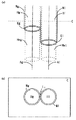
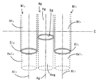
本発明の別の紡糸装置について、液吐出部2箇所とガス吐出部1箇所とを有する紡糸装置の先端部を拡大した斜視図である図4及び図4におけるC平面切断図である図5(a)をもとに説明する。 FIG. 5 is a perspective view in which the tip of the spinning device having two liquid discharge portions and one gas discharge portion is enlarged for another spinning device of the present invention, and is a C plane cut view in FIG. A description will be given based on a).
この紡糸装置は加熱溶融したポリマーの紡糸液を吐出できる第1液吐出部El1を一方の端部に有する第1液吐出ノズルNl1と、加熱溶融したポリマーの紡糸液を吐出できる第2液吐出部El2を一方の端部に有する第2液吐出ノズルNl2とが、加熱ガスを吐出できるガス吐出部Egを一方の端部に有するガス吐出ノズルNgを挟むように外壁面が当接し、ガス吐出ノズルNgのガス吐出部Egが第1液吐出部El1、第2液吐出部El2のいずれよりも上流側となる位置にある。なお、第1液吐出ノズルNl1は第1液吐出部El1を端部とする第1液用柱状中空部Hl1を有し、第2液吐出ノズルNl2は第2液吐出部El2を端部とする第2液用柱状中空部Hl2を有し、ガス吐出ノズルNgはガス吐出部Egを端部とするガス用柱状中空部Hgを有している。また、前記第1液用柱状中空部Hl1を延長した第1液仮想柱状部Hvl1と前記ガス用柱状中空部Hgを延長したガス仮想柱状部Hvgとは、第1液吐出ノズルNl1の壁厚とガス吐出ノズルNgの壁厚の和に相当する距離だけ離れて近接した状態にあり、前記第2液用柱状中空部Hl2を延長した第2液仮想柱状部Hvl2と前記ガス用柱状中空部Hgを延長したガス仮想柱状部Hvgとは、第2液吐出ノズルNl2の壁厚とガス吐出ノズルNgの壁厚の和に相当する距離だけ離れて近接した状態にある。しかも前記第1液用柱状中空部Hl1の第1吐出方向中心軸Al1とガス用柱状中空部Hgの吐出方向中心軸Agとが平行である関係にあり、前記第2液用柱状中空部Hl2の第2吐出方向中心軸Al2とガス用柱状中空部Hgの吐出方向中心軸Agとが平行である関係にある。更には、ガス用柱状中空部Hgの中心軸Agに対して垂直な平面で切断した時に、ガス用柱状中空部Hgの切断面の外形が円形であり、液用柱状中空部Hl1、Hl2の切断面の外形がいずれも円形であり、ガス用柱状中空部Hgの切断面の外周と液用柱状中空部Hl1、Hl2の切断面の外周との距離が最も短い直線L1、L2を、いずれの組み合わせにおいても、1本だけ引くことができる状態にある(図5(a)参照)。 This spinning device includes a first liquid discharge nozzle Nl 1 having a first liquid discharge part El 1 at one end capable of discharging a heated and melted polymer spinning liquid, and a second liquid capable of discharging a heated and melted polymer spinning liquid. The outer wall surface is in contact with the second liquid discharge nozzle Nl 2 having the discharge part El 2 at one end so as to sandwich the gas discharge nozzle Ng having the gas discharge part Eg at one end capable of discharging the heated gas. The gas discharge part Eg of the gas discharge nozzle Ng is in a position on the upstream side of both the first liquid discharge part El 1 and the second liquid discharge part El 2 . The first liquid discharge nozzle Nl 1 has a first liquid columnar hollow part Hl 1 with the first liquid discharge part El 1 as an end, and the second liquid discharge nozzle Nl 2 is the second liquid discharge part El 2. the a second liquid columnar hollow for Hl 2 to end, the gas discharge nozzle Ng has a gas columnar hollow for Hg to end the gas discharge portion Eg. Further, wherein the first liquid columnar hollow for the first liquid virtual columnar portion Hvl 1 and extended gas virtual columnar portion Hvg the columnar hollow Hg for the gas extending the Hl 1, the first liquid discharge nozzle Nl 1 It is in a state close to a distance corresponding to the sum of the wall thickness of the wall and the gas discharge nozzle Ng, second liquid virtual columnar portion Hvl 2 and for the gas extending the columnar hollow Hl 2 for the second liquid the columnar hollow gas virtual columnar portion Hvg which extended Hg, is in a state close to a distance corresponding to the sum of the wall thicknesses of the second liquid wall thickness of the discharge nozzle Nl 2 and the gas discharge nozzle Ng. Moreover, the first liquid columnar hollow part Hl 1 has a relationship in which the first discharge direction central axis Al 1 and the gas columnar hollow part Hg discharge direction central axis Ag are in parallel, and the second liquid columnar hollow part Hl and discharge direction central axis Ag of the second second ejection direction central axis Al 2 gas columnar hollow for Hg is in a parallel relationship. Further, when the gas columnar hollow part Hg is cut along a plane perpendicular to the central axis Ag of the gas columnar hollow part Hg, the outer shape of the cut surface of the gas columnar hollow part Hg is circular, and the liquid columnar hollow parts Hl 1 , Hl 2. The outer shapes of the cut surfaces are both circular, and the straight lines L1 and L2 having the shortest distances between the outer periphery of the gas columnar hollow portion Hg and the outer periphery of the liquid columnar hollow portions Hl 1 and Hl 2 are shown in FIG. In any combination, only one can be drawn (see FIG. 5A).
そのため、図4のような紡糸装置の第1液吐出ノズルNl1及び第2液吐出ノズルNl2に加熱溶融したポリマーの紡糸液を供給し、ガス吐出ノズルNgに加熱ガスを供給すると、紡糸液は第1液用柱状中空部Hl1、第2液用柱状中空部Hl2をそれぞれ通り、第1液吐出部El1、第2液吐出部El2から第1液用柱状中空部Hl1の第1軸方向、第2液用柱状中空部Hl2の第2軸方向にそれぞれ吐出されると同時に、加熱ガスはガス用柱状中空部Hgを通りガス吐出部Egからガス用柱状中空部Hgの軸方向に吐出される。この吐出された加熱ガスと吐出された各紡糸液とはいずれも近接した状態にあり、各液吐出部の直近においては、吐出ガスの中心軸Agと各吐出紡糸液の中心軸Al1、Al2とがいずれも平行関係にあり、しかもC平面上、吐出された加熱ガスと吐出された紡糸液とは、いずれの組み合わせにおいても最も近い点が1箇所であることから、つまり、いずれの紡糸液も1本の直線状に加熱ガスおよび随伴気流による剪断作用を受け、細径化しながら第1液用柱状中空部Hl1の第1軸方向、第2液用柱状中空部Hl2の第2軸方向にそれぞれ飛翔し、繊維化する。また、1つの加熱ガス流によって、2つの紡糸液を紡糸して繊維化することができ、加熱ガス量を減らすことができるためエネルギー的に有利である。なお、直接不織布を製造する場合には、加熱ガス量を減らすことができるため、集積した繊維の飛散を抑制し、地合いの均一な不織布を製造することができる。また、吸引装置を使用する場合、吸引装置を大型化する必要がないことからエネルギー的に有利であり、また、吸引装置の吸引力を強くする必要がないため、厚さの薄い不織布から厚い不織布まで製造することができる。 Therefore, when the polymer spinning solution heated and melted is supplied to the first liquid discharge nozzle Nl 1 and the second liquid discharge nozzle Nl 2 of the spinning apparatus as shown in FIG. 4 and the heated gas is supplied to the gas discharge nozzle Ng, the spinning liquid Passes through the first liquid columnar hollow part Hl 1 and the second liquid columnar hollow part Hl 2 , respectively, from the first liquid discharge part El 1 and the second liquid discharge part El 2 to the first liquid columnar hollow part Hl 1 . first axial direction simultaneously discharged respectively in a second axial direction of the second liquid columnar hollow for Hl 2, heating gas gas columnar hollow for Hg from the street ejecting gas Eg the columnar hollow for gas (Hg) Discharged in the axial direction. The discharged heated gas and each discharged spinning solution are in close proximity to each other, and in the immediate vicinity of each liquid discharging portion, the central axis Ag of the discharged gas and the central axes Al 1 , Al of each discharged spinning solution 2 are parallel to each other, and on the C plane, the heated gas discharged and the discharged spinning solution have only one point in any combination, that is, any spinning. liquid also subjected to shearing action by the heating gas and the accompanying airstream on one straight line shape, diameter reduction while the first solution for a first axis direction of the columnar hollow Hl 1, a second liquid columnar hollow for Hl 2 second Fly in the axial direction and fiberize. Further, two spinning solutions can be spun and fiberized by one heated gas flow, and the amount of heated gas can be reduced, which is advantageous in terms of energy. In addition, when manufacturing a nonwoven fabric directly, since the amount of heating gas can be reduced, scattering of the accumulated fiber can be suppressed and a nonwoven fabric with uniform texture can be manufactured. Also, when using a suction device, it is advantageous in terms of energy because it is not necessary to increase the size of the suction device, and since it is not necessary to increase the suction force of the suction device, a thin nonwoven fabric is changed from a thin nonwoven fabric. Can be manufactured.
第1液吐出ノズルNl1、第2液吐出ノズルNl2は加熱溶融したポリマーの紡糸液を吐出できるものであれば良く、第1液吐出部El1、第2液吐出部El2の外形は特に限定するものではなく、例えば、円形、長円形、楕円形、多角形(例えば、三角形、四角形、六角形)であることができる。加熱ガス及び随伴気流の剪断作用を1本の直線状に作用を受け、ショットやビーズ(粒子形状の樹脂)を生じにくいように、円形であるのが好ましい。つまり、第1液吐出ノズルNl1、第2液吐出ノズルNl2の外形が円形であると、ガス用柱状中空部Hgの中心軸Agに対して垂直な平面で切断した時に、ガス用柱状中空部Hgの切断面の外周と液用柱状中空部Hl1、Hl2の切断面の外周との距離が最も短い直線L1、L2を、いずれの組み合わせにおいても1本だけ引くことができる状態となりやすいため、吐出された紡糸液は加熱ガス及び随伴気流の剪断作用を1本の直線状に受け、ショットやビーズ(粒子形状の樹脂)を生じにくくなる。なお、第1液吐出部El1と第2液吐出部El2の外形は同じ外形であっても良いし、異なる外形であっても良いが、いずれも円形であるのが好ましい。 The first liquid discharge nozzle Nl 1 and the second liquid discharge nozzle Nl 2 are only required to be able to discharge a heated and melted polymer spinning solution. The outer shapes of the first liquid discharge part El 1 and the second liquid discharge part El 2 are as follows. For example, the shape may be a circle, an oval, an ellipse, or a polygon (for example, a triangle, a quadrangle, or a hexagon). A circular shape is preferred so that the shearing action of the heated gas and the accompanying airflow is affected in a straight line, and shots and beads (particle-shaped resin) are less likely to occur. In other words, when the outer shapes of the first liquid discharge nozzle Nl 1 and the second liquid discharge nozzle Nl 2 are circular, the gas columnar hollow when cut by a plane perpendicular to the central axis Ag of the gas columnar hollow portion Hg. The straight line L1, L2 having the shortest distance between the outer periphery of the cut surface of the part Hg and the outer periphery of the liquid columnar hollow portions Hl 1 , Hl 2 is likely to be in a state where only one line can be drawn in any combination. Therefore, the discharged spinning solution is subjected to the shearing action of the heating gas and the accompanying airflow in a single straight line, and is less likely to generate shots and beads (particle-shaped resin). Note that the outer shape of the first liquid discharge unit El 1 and the second liquid discharge unit El 2 may be the same or different, but both are preferably circular.
第1液吐出部El1、第2液吐出部El2の形状が多角形である場合には、多角形の1つの角をガス吐出ノズルNg側となるように配置することにより、加熱ガス及び随伴気流の剪断作用を1本の直線状に受け、ショットやビーズ(粒子形状の樹脂)を生じにくくするのが好ましい。つまり、ガス用柱状中空部Hgの中心軸Agに対して垂直な平面で切断した時に、ガス用柱状中空部Hgの切断面の外周と第1液用柱状中空部Hl1、第2液用柱状中空部Hl2の切断面の外周との距離が最も短い直線(図5(a)〜(e)におけるL1、L2)を、いずれの組み合わせにおいても、1本だけ引くことができるように第1液吐出ノズルNl1、第2液吐出ノズルNl2を配置すると、紡糸液は加熱ガス及び随伴気流の剪断作用を1本の直線状に受け、安定して紡糸でき、ショットやビーズ(粒子形状の樹脂)を生じにくくなる。したがって、ガス吐出部Egの形状が円形であれば、多角形状の第1液吐出部El1、第2液吐出部El2の辺をガス吐出ノズルNg側となるように配置することも可能である(図5(e)参照)。 When the shapes of the first liquid discharge unit El 1 and the second liquid discharge unit El 2 are polygons, the heating gas and the gas are disposed by arranging one corner of the polygon on the gas discharge nozzle Ng side. It is preferable that the shearing action of the accompanying airflow is received in a single straight line so that shots and beads (particle-shaped resin) are less likely to occur. That is, when cut along a plane perpendicular to the central axis Ag of the gas columnar hollow portion Hg, the outer periphery of the cut surface of the gas columnar hollow portion Hg, the first liquid columnar hollow portion Hl 1 , and the second liquid columnar shape. the distance between the outer periphery of the cut surface of the hollow portion Hl 2 shortest straight line (FIG. 5 (L1 in a) ~ (e), L2 ), in any combination, first to be able to draw only one 1 When the liquid discharge nozzle Nl 1 and the second liquid discharge nozzle Nl 2 are arranged, the spinning liquid is subjected to the shearing action of the heated gas and the accompanying airflow in a single straight line, and can be stably spun. Resin). Therefore, if the shape of the gas discharge part Eg is circular, the sides of the polygonal first liquid discharge part El 1 and the second liquid discharge part El 2 can be arranged on the gas discharge nozzle Ng side. Yes (see FIG. 5 (e)).
また、第1液吐出部El1及び第2液吐出部El2の大きさも特に限定するものではないが、いずれも0.01〜20mm2であるのが好ましく、0.01〜2mm2であるのがより好ましい。0.01mm2よりも小さいと、粘度の高い紡糸液を吐出するのが困難になる傾向があり、20mm2を超えると、加熱ガス及び随伴気流の作用を1本の直線状にするのが難しくなり、安定して紡糸できなくなる傾向があるためである。 Further, although not the size of the first liquid ejection unit El 1 and the second liquid ejection unit El 2 is also limited particularly, but is preferably either a 0.01 to 20 mM 2, is 0.01 to 2 mm 2 Is more preferable. If it is smaller than 0.01 mm 2 , it tends to be difficult to discharge a spinning solution having a high viscosity, and if it exceeds 20 mm 2 , it is difficult to make the action of the heating gas and the accompanying air flow straight. This is because there is a tendency that spinning cannot be performed stably.
なお、第1液吐出ノズルNl1及び第2液吐出ノズルNl2の材質は特に限定するものではないが、加熱溶融したポリマーを吐出することから金属製であるのが好ましい。また、金属製のチューブを用いることもできる。更に、図4においては、円柱状の第1液吐出ノズルNl1及び第2液吐出ノズルNl2を図示しているが、先端が傾斜を持って切断された鋭角ノズルを使用することもできる。この鋭角ノズルの場合、紡糸液の粘度が高い場合に有効である。このような鋭角ノズルを使用する場合、尖った側をガス吐出ノズル側とすると、加熱ガス及び随伴気流の剪断作用を受けやすく、安定して繊維化できる。 The materials of the first liquid discharge nozzle Nl 1 and the second liquid discharge nozzle Nl 2 are not particularly limited, but are preferably made of metal since the heated and melted polymer is discharged. A metal tube can also be used. Further, in FIG. 4, the cylindrical first liquid discharge nozzle Nl 1 and the second liquid discharge nozzle Nl 2 are illustrated, but it is also possible to use an acute angle nozzle whose tip is cut with an inclination. This acute angle nozzle is effective when the spinning solution has a high viscosity. When such an acute nozzle is used, if the sharp side is the gas discharge nozzle side, it is easy to be subjected to the shearing action of the heated gas and the accompanying airflow, and can be stably fiberized.
なお、図4においては、第1液吐出ノズルNl1と第2液吐出ノズルNl2の2本について図示しているが、液吐出ノズルは2本である必要はなく、3本以上であっても良い(図6参照)。この液吐出ノズルの本数が多ければ多いほど、加熱ガスを効率的に利用し、生産性良く紡糸することができる。 In FIG. 4, two of the first liquid discharge nozzle Nl 1 and the second liquid discharge nozzle Nl 2 are illustrated, but the number of liquid discharge nozzles is not necessarily two, and three or more. (See FIG. 6). The larger the number of liquid discharge nozzles, the more efficiently the heated gas can be used for spinning with high productivity.
ガス吐出ノズルNgは加熱ガスを吐出できるものであれば良く、ガス吐出部Egの形状は特に限定するものではなく、例えば、円形、長円形、楕円形、多角形(例えば、三角形、四角形、六角形)であることができる。ガス吐出部に対して各液吐出部をどのように配置しても、各液吐出部から吐出された各紡糸液に、ガス吐出部から吐出された加熱ガスおよび随伴気流による剪断力をそれぞれ1本の直線状に作用させ、細径化した繊維を紡糸しやすいように、円形であるのが好ましい。なお、ガス吐出部Egの形状が多角形である場合には、多角形の1つの角を第1液吐出ノズルNl1側となり、もう1つの角が第2液吐出ノズルNl2側となるように配置することにより、加熱ガス及び随伴気流の剪断作用が働きやすくなる。つまり、前述の通り、ガス用柱状中空部Hgの中心軸Agに対して垂直な平面で切断した時に、ガス用柱状中空部Hgの切断面の外周と第1液用柱状中空部Hl1、第2液用柱状中空部Hl2の切断面の外周との距離が最も短い直線L1、L2を、いずれの組み合わせにおいても、1本だけ引くことができる状態となるように第1液吐出ノズルNl1、第2液吐出ノズルNl2を配置する(図5(c)〜(d)参照)と、紡糸液は加熱ガス及び随伴気流の剪断作用を1本の直線状に受け、ショットやビーズ(粒子形状の樹脂)を生じにくくなる。 The gas discharge nozzle Ng only needs to be able to discharge heated gas, and the shape of the gas discharge portion Eg is not particularly limited. For example, the shape is circular, oval, elliptical, polygonal (for example, triangle, quadrilateral, six Square). Regardless of how each liquid discharge section is arranged with respect to the gas discharge section, each spinning solution discharged from each liquid discharge section is subjected to a shearing force generated by the heated gas discharged from the gas discharge section and the accompanying air flow by 1 each. A circular shape is preferred so that the fibers can be made to act in a straight line and can be easily spun. When the shape of the gas discharge portion Eg is a polygon, one corner of the polygon is on the first liquid discharge nozzle Nl 1 side, and the other corner is on the second liquid discharge nozzle Nl 2 side. By arrange | positioning to, the shearing effect | action of heating gas and an accompanying airflow becomes easy to work. That is, as described above, when cut along a plane perpendicular to the central axis Ag of the gas columnar hollow part Hg, the outer periphery of the cut surface of the gas columnar hollow part Hg and the first liquid columnar hollow part Hl 1 , The first liquid discharge nozzle Nl 1 so that only one straight line L1, L2 having the shortest distance from the outer periphery of the cut surface of the two liquid columnar hollow part Hl 2 can be drawn in any combination. When the second liquid discharge nozzle Nl 2 is disposed (see FIGS. 5C to 5D), the spinning liquid receives the shearing action of the heating gas and the accompanying air flow in a single straight line, and shots and beads (particles) (Resin in shape) is less likely to occur.
また、ガス吐出部Egの大きさも特に限定するものではないが、0.01〜79mm2であるのが好ましく、0.015〜20mm2であるのがより好ましい。0.01mm2よりも小さいと、吐出された各紡糸液全体に剪断作用を働かせることが困難になる傾向があり、安定して繊維化することが困難になる傾向があるためで、79mm2を超えると剪断作用を働かせるために十分な風速が必要で、多量の加熱ガスが必要となって不経済であるためである。 Although not limited to particular also the size of the gas discharge portion Eg, is preferably from 0.01~79Mm 2, and more preferably 0.015~20mm 2. When less than 0.01 mm 2, there is a tendency that it becomes difficult to exert a shearing action across the spinning solution discharged, stabilized with because it tends to be difficult to fiberizing by the 79 mm 2 This is because if it exceeds, a sufficient wind speed is required to make the shearing action work, and a large amount of heated gas is required, which is uneconomical.
なお、ガス吐出ノズルNgの材料は特に限定するものではないが、加熱ガスを吐出するため金属製であるのが好ましい。また、ガス吐出ノズルに替えて金属製チューブを用いることもできる。 The material of the gas discharge nozzle Ng is not particularly limited, but is preferably made of metal in order to discharge the heated gas. In addition, a metal tube can be used instead of the gas discharge nozzle.
ガス吐出ノズルNgはガス吐出部Egが第1液吐出部El1及び第2液吐出部El2よりも上流側(紡糸液の供給側)となる位置に配置されているため、第1液吐出部El1及び第2液吐出部El2の周辺へ紡糸液が巻き上がるのを防止できる。そのため、液吐出部を汚すことなく、長時間の紡糸が可能である。なお、ガス吐出部Egと第1液吐出部El1又は第2液吐出部El2との距離は特に限定するものではないが、10mm以下であることが好ましく、5mm以下であることがより好ましい。10mmを超えると第1液吐出部El1又は第2液吐出部El2における加熱ガス及び随伴気流の剪断力が不十分となり、繊維化しにくくなる傾向があるためである。ガス吐出部Egと第1液吐出部El1及び第2液吐出部El2との距離の下限は特に限定するものではなく、ガス吐出部Egと第1液吐出部El1及び第2液吐出部El2とが一致していなければ良い。 The gas discharge nozzle Ng is disposed at a position where the gas discharge portion Eg is located upstream of the first liquid discharge portion El 1 and the second liquid discharge portion El 2 (spinning liquid supply side). It is possible to prevent the spinning solution from winding up around the part El 1 and the second liquid discharge part El 2 . Therefore, it is possible to perform spinning for a long time without polluting the liquid discharge part. The distance between the gas discharge part Eg and the first liquid discharge part El 1 or the second liquid discharge part El 2 is not particularly limited, but is preferably 10 mm or less, and more preferably 5 mm or less. . If it exceeds 10 mm, the shearing force of the heating gas and the accompanying airflow in the first liquid discharge part El 1 or the second liquid discharge part El 2 becomes insufficient, and it tends to be difficult to be fiberized. The lower limit of the distance between the gas discharge part Eg and the first liquid discharge part El 1 and the second liquid discharge part El 2 is not particularly limited, and the gas discharge part Eg, the first liquid discharge part El 1 and the second liquid discharge are not limited. It is sufficient if the part El 2 does not match.
なお、ガス吐出部Egと第1液吐出部El1又は第2液吐出部El2との距離は同じであっても異なっていても良いが、同じであると、各紡糸液に対して同程度の剪断力を作用させることができ、安定して紡糸できるため好適である。 The distance between the gas discharge part Eg and the first liquid discharge part El 1 or the second liquid discharge part El 2 may be the same or different, but if they are the same, the same for each spinning liquid. A shearing force of a certain degree can be applied, and spinning is possible stably.
第1液用柱状中空部Hl1及び第2液用柱状中空部Hl2は紡糸液の通過経路であり、紡糸液の吐出時における形状を形作り、ガス用柱状中空部Hgは加熱ガスの通過経路であり、加熱ガスの吐出時における形状を形作る。本発明においては、第1液用柱状中空部Hl1、第2液用柱状中空部Hl2、ガス用柱状中空部Hgのいずれも柱状の紡糸液又は加熱ガスを形成できるため、加熱ガス及び随伴気流の剪断作用を各紡糸液に十分に作用させることができ、繊維化することができる。 First liquid columnar hollow for Hl 1 and the second liquid columnar hollow for Hl 2 is a passing path of the spinning solution, shape the shape at the time of discharge of the spinning liquid, the columnar hollow for gas (Hg) passing the heated gas path It forms the shape when the heated gas is discharged. In the present invention, since any of the first liquid columnar hollow part H1 1 , the second liquid columnar hollow part Hl 2 , and the gas columnar hollow part Hg can form a columnar spinning liquid or heating gas, the heating gas and the accompanying gas The shearing action of the airflow can be sufficiently applied to each spinning solution and can be made into fibers.
なお、第1液用柱状中空部Hl1を延長した第1液仮想柱状部Hvl1は第1液吐出部El1から吐出された紡糸液の吐出直後の飛翔経路であり、第2液用柱状中空部Hl2を延長した第2液仮想柱状部Hvl2は第2液吐出部El2から吐出された紡糸液の吐出直後の飛翔経路であり、ガス用柱状中空部Hgを延長したガス仮想柱状部Hvgはガス吐出部Egから吐出された加熱ガスの吐出直後の噴出経路である。この第1液仮想柱状部Hvl1とガス仮想柱状部Hvgとの距離は第1液吐出ノズルNl1の壁厚とガス吐出ノズルNgの壁厚の和に相当し、第2液仮想柱状部Hvl2とガス仮想柱状部Hvgとの距離は第2液吐出ノズルNl2の壁厚とガス吐出ノズルNgの壁厚の和に相当しているが、これら距離は2mm以下であることが好ましく、1mm以下であることがより好ましい。2mmを超えると加熱ガス及び随伴気流の剪断力が作用しにくく、繊維化しにくくなる傾向があるためである。 The first liquid virtual columnar part Hvl 1 extending from the first liquid columnar hollow part Hl 1 is a flight path immediately after the discharge of the spinning solution discharged from the first liquid discharge part El 1 , and the second liquid columnar part The second liquid virtual columnar part Hvl 2 extending the hollow part Hl 2 is a flight path immediately after the spinning liquid discharged from the second liquid discharge part El 2 is discharged, and the gas virtual columnar part extending the gas columnar hollow part Hg. Part Hvg is an ejection path immediately after ejection of the heated gas ejected from the gas ejection part Eg. The first liquid distance between the virtual columnar portion Hvl 1 and the gas virtual columnar portion Hvg corresponds to the sum of the wall thicknesses of the first liquid ejection wall thickness of the nozzle Nl 1 and the gas discharge nozzle Ng, second liquid virtual columnar portion Hvl 2 is equivalent to the sum of the wall thickness of the second liquid discharge nozzle Nl 2 and the wall thickness of the gas discharge nozzle Ng, but the distance is preferably 2 mm or less. The following is more preferable. This is because if the thickness exceeds 2 mm, the shearing force of the heating gas and the accompanying airflow hardly acts, and the fiber tends to be difficult to be formed.
この第1液仮想柱状部Hvl1、第2液仮想柱状部Hvl2、ガス仮想柱状部Hvgのいずれも内部充実した柱状である。例えば、円柱状の第1又は第2液仮想部を中空円柱状のガス仮想部で覆った状態、又は円柱状のガス仮想部を中空円柱状の第1又は第2液仮想部で覆った状態であると、ガス仮想柱状部Hvgの中心軸Agに対して垂直な平面で切断した時に、第1又は第2液仮想部の切断面の外周とガス仮想部の切断面の内周、又はガス仮想部の切断面の外周と第1又は第2液仮想部の切断面の内周との距離が最も短い直線を無数に引くことができる結果、紡糸液の様々な点で加熱ガス及び随伴気流の剪断力が作用し、繊維化が不十分となり、ショット、或いはビーズ(粒子形状の樹脂)が多くなるためである。この「仮想柱状部」はノズルの内壁面を延長して形成される部分である。 All of the first liquid virtual columnar part Hvl 1 , the second liquid virtual columnar part Hvl 2 , and the gas virtual columnar part Hvg have a solid columnar shape. For example, a state in which the cylindrical first or second liquid virtual part is covered with a hollow cylindrical gas virtual part, or a state in which the cylindrical gas virtual part is covered with a hollow cylindrical first or second liquid virtual part When cut by a plane perpendicular to the center axis Ag of the gas virtual columnar part Hvg, the outer periphery of the cut surface of the first or second liquid virtual part and the inner periphery of the cut surface of the gas virtual part, or gas As a result of being able to draw an infinite number of straight lines with the shortest distance between the outer periphery of the cut surface of the imaginary part and the inner periphery of the cut surface of the first or second liquid imaginary part, the heated gas and the accompanying air flow at various points of the spinning solution This is because the shearing force acts, and the fiberization becomes insufficient, resulting in an increase in shots or beads (particle-shaped resin). This “virtual columnar portion” is a portion formed by extending the inner wall surface of the nozzle.
更に、第1液用柱状中空部Hl1の第1吐出方向中心軸Al1とガス用柱状中空部Hgの吐出方向中心軸Agとが平行であり、また、第2液用柱状中空部Hl2の第2吐出方向中心軸Al2とガス用柱状中空部Hgの吐出方向中心軸Agとが平行であるため、吐出された紡糸液に対して加熱ガス及び随伴気流が1本の直線状に作用し、安定して繊維を形成することができる。例えば、円柱状の第1又は第2液用中空部を中空円柱状のガス中空部で覆った状態、又は円柱状のガス中空部を中空円柱状の第1又は第2液用中空部で覆った状態であるように、これら中心軸が一致すると、加熱ガス及び随伴気流の剪断力を1本の直線状に作用させることができず、繊維化が不安定となり、ショット、或いはビーズ(粒子形状の樹脂)が多くなる。また、これら中心軸が交差又はねじれの位置にあると、加熱ガス及び随伴気流による剪断力が作用しないか、作用したとしても不均一であることから、安定して繊維を形成することができない。この「平行」であるとは、第1又は第2液用柱状中空部の吐出方向中心軸とガス用柱状中空部の吐出方向中心軸とが同一平面上に位置することができ、しかも平行であることを意味する。また、「吐出方向中心軸」とは吐出部の中心と仮想柱状部の横断面における中心とを結んでできる直線である。 Further, the first discharge direction central axis Al 1 of the first liquid columnar hollow part Hl 1 and the discharge direction central axis Ag of the gas columnar hollow part Hg are parallel, and the second liquid columnar hollow part Hl 2. second for the discharge direction center axis Ag of the ejection direction central axis Al 2 gas columnar hollow for Hg are parallel, the heating gas and the accompanying airstream relative to the discharged spinning solution is applied to a single linear In addition, the fibers can be formed stably. For example, the cylindrical first or second liquid hollow part is covered with a hollow cylindrical gas hollow part, or the cylindrical gas hollow part is covered with a hollow cylindrical first or second liquid hollow part. When the central axes coincide with each other, the shearing force of the heating gas and the accompanying air current cannot be applied in a straight line, and the fiberization becomes unstable, and shots or beads (particle shape) Resin). Further, if these central axes are at the crossing or twisting positions, the shearing force due to the heating gas and the accompanying airflow does not act or even if it acts, the fibers cannot be formed stably. The term “parallel” means that the central axis in the discharge direction of the first or second liquid columnar hollow part and the central axis in the discharge direction of the gas columnar hollow part can be located on the same plane and are parallel to each other. It means that there is. Further, the “ejection direction central axis” is a straight line formed by connecting the center of the ejection part and the center of the cross section of the virtual columnar part.
本発明の紡糸装置はガス用柱状中空部Hgの中心軸Agに対して垂直な平面で切断した時に、ガス用柱状中空部Hgの切断面の外周と第1液用柱状中空部Hl1の切断面の外周との距離が最も短い直線L1を1本だけ引くことができ、ガス用柱状中空部Hgの切断面の外周と第2液用柱状中空部Hl2の切断面の外周との距離が最も短い直線L2を1本だけ引くことができる。このようなガス用柱状中空部Hgから吐出された加熱ガス及び随伴気流は、第1液用柱状中空部Hl1から吐出された紡糸液と第2液用柱状中空部Hl2から吐出された紡糸液のいずれに対しても1本の直線状に作用し、剪断作用を発揮することができるため、ショットやビーズ(粒子形状の樹脂)を生じることなく、安定して紡糸することができる。例えば、前記直線を2本引くことができる場合には、一方の点で作用する場合と他方の点で作用する場合とが交互になるなど、安定して剪断作用を発揮することができない結果、ショットやビーズ(粒子形状の樹脂)を発生し、安定して紡糸することができない。 When cut along a plane perpendicular to the central axis Ag of the spinning device columnar hollow for gas (Hg) of the present invention, the cutting of the outer periphery and the columnar hollow Hl 1 for the first liquid in the cut surface of the columnar hollow for gas (Hg) the straight line L1 shortest distance between the outer peripheral surface can be drawn only one, the distance between the outer periphery of the outer periphery cut surface of the second liquid columnar hollow for Hl 2 of the cut surface of the columnar hollow for gas (Hg) Only one shortest straight line L2 can be drawn. Such heating gas and the accompanying airstream is discharged from the columnar hollow for gas (Hg) is spinning a first liquid columnar hollow for Hl 1 from ejected spinning solution discharged from the columnar hollow Hl 2 for the second fluid Since any one of the liquids acts in a straight line and exerts a shearing action, it can be stably spun without producing shots or beads (particle-shaped resin). For example, in the case where two straight lines can be drawn, the case of acting at one point and the case of acting at the other point are alternated. Shots and beads (particle-shaped resin) are generated and cannot be stably spun.
なお、図4には図示していないが、第1液吐出ノズルNl1及び第2液吐出ノズルNl2は加熱溶融したポリマーを供給できる供給装置(例えば、押出し機、ヒーターにより加熱された金属製シリンジなど)に接続されており、ガス吐出ノズルNgは加熱ガスを供給できる供給装置(例えば、ヒーターに接続した圧縮機、ガスボンベ、ブロアなど)に接続されている。 Although not shown in FIG. 4, the first liquid discharge nozzle Nl 1 and the second liquid discharge nozzle Nl 2 are each a supply device (for example, a metal heated by an extruder or a heater) that can supply a heated and melted polymer. The gas discharge nozzle Ng is connected to a supply device (for example, a compressor connected to a heater, a gas cylinder, a blower, etc.) that can supply heated gas.
図4においては、1組の紡糸装置しか描いていないが、2組以上の紡糸装置を配置することができる。2組以上の紡糸装置を配置することによって、生産性を更に高めることができる。 In FIG. 4, only one set of spinning devices is shown, but two or more sets of spinning devices can be arranged. Productivity can be further enhanced by arranging two or more spinning devices.
また、図4においては、第1液吐出ノズルNl1、第2液吐出ノズルNl2、及びガス吐出ノズルNgとを固定した状態にあるが、前述のような関係を満たす限り、図4の態様に限定されない。例えば、段差を有する基材に対して第1液用柱状中空部Hl1、第2液用柱状中空部Hl2、ガス用柱状中空部Hgを穿孔したものであっても良い。また、第1液吐出ノズルNl1の第1液吐出部El1、第2液吐出ノズルNl2の第2液吐出部El2、及び/又はガス吐出ノズルNgのガス吐出部Egの位置を自由に調整できる機構を備えていることもできる。 In FIG. 4, the first liquid discharge nozzle Nl 1 , the second liquid discharge nozzle Nl 2 , and the gas discharge nozzle Ng are in a fixed state, but as long as the relationship as described above is satisfied, the mode of FIG. It is not limited to. For example, the first liquid columnar hollow part Hl 1 , the second liquid columnar hollow part Hl 2 , and the gas columnar hollow part Hg may be perforated on a substrate having a step. The first liquid ejection unit El 1 of the first liquid discharge nozzle Nl 1, the second liquid ejection unit El 2 of the second liquid discharge nozzle Nl 2, and / or the position of the exit for ejecting gas (Eg) of the gas discharge nozzle Ng free It is also possible to provide a mechanism that can be adjusted.
本発明の不織布製造装置は前述のような紡糸装置に加えて、繊維の捕集体を備えているため、繊維を捕集して不織布を製造することができる。本発明の不織布製造装置について、不織布製造装置の模式的断面説明図である図7を参照しながら説明する。 Since the nonwoven fabric manufacturing apparatus of the present invention includes a fiber collector in addition to the spinning device as described above, the nonwoven fabric can be manufactured by collecting the fibers. The nonwoven fabric manufacturing apparatus of this invention is demonstrated referring FIG. 7 which is typical sectional explanatory drawing of a nonwoven fabric manufacturing apparatus.
図7の不織布製造装置は前述のような2つの液吐出ノズルを有する紡糸装置1に加えて、紡糸された繊維を捕集できる捕集体3、捕集体3の下流側に位置し、紡糸された繊維を吸引できるサクション装置4を備えている。なお、紡糸装置1には加熱溶融したポリマーを第1液吐出ノズルNl1へ供給できる第1紡糸液供給装置、及び同じ又は異なる加熱溶融したポリマーを第2液吐出ノズルNl2へ供給できる第2紡糸液供給装置が接続され、加熱ガスをガス吐出ノズルNgへ供給できる加熱ガス供給装置が接続されている。
In addition to the
このような不織布製造装置の場合、紡糸液は第1紡糸溶液供給装置及び第2紡糸溶液供給装置によって、第1液吐出ノズルNl1、第2液吐出ノズルNl2へそれぞれ供給されると同時に、加熱ガス供給装置によって加熱ガスがガス吐出ノズルNgへ供給される。そのため、第1液吐出ノズルNl1及び第2液吐出ノズルNl2から吐出された紡糸液は、それぞれガス吐出ノズルNgから吐出された加熱ガスの剪断作用によって延伸され、繊維化するとともに、これら繊維は均一に混合しながら、捕集体3へ向かって飛翔し、この飛翔した繊維は直接、捕集体3上に集積し、不織布を形成する。 In the case of such a nonwoven fabric manufacturing apparatus, the spinning solution is supplied to the first liquid discharge nozzle Nl 1 and the second liquid discharge nozzle Nl 2 by the first spinning solution supply device and the second spinning solution supply device, respectively, The heated gas is supplied to the gas discharge nozzle Ng by the heated gas supply device. Therefore, the spinning liquid discharged from the first liquid discharge nozzle Nl 1 and the second liquid discharge nozzle Nl 2 is stretched and fiberized by the shearing action of the heated gas discharged from the gas discharge nozzle Ng, respectively. Flies toward the collector 3 while being uniformly mixed, and the flying fibers are directly accumulated on the collector 3 to form a nonwoven fabric.
図7の不織布製造装置においては、1つのガス吐出ノズルに対して2つ以上の液吐出ノズルを配置した紡糸装置を使用しており、吐出ガス量を少なくすることができるため、集積した繊維の飛散を抑制して地合いの均一な不織布を生産性良く製造できる。また、加熱ガス量を減らすことができ、サクション装置4を大型化する必要がないためエネルギー的に有利である。 In the nonwoven fabric manufacturing apparatus of FIG. 7, a spinning device in which two or more liquid discharge nozzles are arranged for one gas discharge nozzle is used, and the amount of discharged gas can be reduced. A non-woven fabric with uniform texture can be produced with good productivity by suppressing scattering. Moreover, since the amount of heated gas can be reduced and the suction device 4 does not need to be enlarged, it is advantageous in terms of energy.
なお、この繊維を集積する際に、捕集体3の下流側にはサクション装置4が配置されているため、ガス吐出ノズルNgから吐出された加熱ガスは速やかに排出され、加熱ガスの作用によって不織布が乱れるということがない。 In addition, when collecting this fiber, since the suction device 4 is arrange | positioned in the downstream of the collection body 3, the heating gas discharged from the gas discharge nozzle Ng is discharged | emitted rapidly, and a nonwoven fabric by the effect | action of heating gas Is not disturbed.
図7においては、コンベアからなる捕集体3であるが、捕集体3は繊維を直接集積できるものであれば良く、例えば、不織布、織物、編物、ネット、ドラム、ベルト或いは平板を捕集体として使用できる。また、図7においては、加熱ガスを吐出しているため、加熱ガスを吸引して捕集体上に繊維を集積しやすく、また集積した繊維が乱れないように、通気性の捕集体を使用し、捕集体の紡糸装置側とは反対面側にサクション装置4を設置するのが好ましい。なお、サクション装置4を使用しない場合には、捕集体は通気性である必要はない。 In FIG. 7, it is the collection body 3 which consists of conveyors, However, The collection body 3 should just be what can accumulate | store fiber directly, for example, uses a nonwoven fabric, a woven fabric, a knitted fabric, a net | network, a drum, a belt, or a flat plate as a collection body. it can. In FIG. 7, since the heated gas is discharged, a breathable collector is used so that the heated gas is sucked to easily collect the fibers on the collector and the accumulated fibers are not disturbed. The suction device 4 is preferably installed on the side of the collecting body opposite to the spinning device side. When the suction device 4 is not used, the collector need not be air permeable.
図7においては、捕集体3を紡糸装置1の第1液吐出ノズルNl1及び第2液吐出ノズルNl2からの吐出方向下側(重力の作用方向)に配置し、第1液吐出ノズルNl1及び第2液吐出ノズルNl2の吐出方向と捕集体3の捕集面とが直交する位置関係にあるが、第1液吐出ノズルNl1及び第2液吐出ノズルNl2からの吐出方向と捕集体3の捕集面とが平行である位置関係にあっても、第1液吐出ノズルNl1及び第2液吐出ノズルNl2からの吐出方向と捕集体3の捕集面とが交差する位置関係にあっても良い。なお、第1液吐出ノズルNl1及び第2液吐出ノズルNl2からの吐出方向は重力の作用方向と同じであっても、重力の作用方向と反対方向であっても、重力の作用方向と直交する方向であっても、重力の作用方向と交差する方向であっても良く、特に限定するものではない。
In FIG. 7, the collection body 3 is arranged on the lower side in the discharge direction (the direction of the action of gravity) from the first liquid discharge nozzle Nl 1 and the second liquid discharge nozzle Nl 2 of the
なお、捕集体3を紡糸装置1のガス吐出部Egと対向して配置、特に直角に配置する場合、捕集体3の捕集面と紡糸装置1の第1液吐出ノズルNl1及び第2液吐出ノズルNl2との距離は、紡糸液の吐出量や加熱ガス流速によって変化するため特に限定するものではないが、10〜1000mmであるのが好ましい。10mm未満であると、加熱ガスなどの影響を受けて、捕集体上に集積した繊維が溶けてしまったり、或いは、繊維同士が溶着する傾向があるためであり、1000mmを超えると、加熱ガスの流れが乱れ、繊維が切れて飛散しやすくなる傾向があるためである。
The arrangement of the collector body 3 and the exit for ejecting gas (Eg) and the counter of the
サクション装置4は特に限定するものではないが、加熱ガス供給装置からのガス供給量、製造する不織布の厚さによって風速条件を調整できるものが好ましい。 The suction device 4 is not particularly limited, but is preferably one that can adjust the wind speed condition depending on the gas supply amount from the heated gas supply device and the thickness of the nonwoven fabric to be manufactured.
なお、第1紡糸液供給装置又は第2紡糸液供給装置としては、例えば、押出し機、ヒーターにより加熱された金属製シリンジなどを挙げることができ、加熱ガス供給装置として、例えば、ヒーターに接続した圧縮機、ガスボンベ、ブロアなどを挙げることができる。 The first spinning solution supply device or the second spinning solution supply device can include, for example, an extruder, a metal syringe heated by a heater, and the heated gas supply device is connected to a heater, for example. A compressor, a gas cylinder, a blower, etc. can be mentioned.
図7の不織布製造装置においては、紡糸装置1を1台だけ配置しているが、1台である必要はなく、2台以上配置することができる。2台以上配置することによって不織布の生産性を高めることができる。また、図7の不織布製造装置においては、1本のガス吐出ノズルに対して2本の液吐出ノズルを配置した紡糸装置1を使用しているが、1本のガス吐出ノズルに対して3本以上の液吐出ノズルを配置した紡糸装置を使用することもできる。
In the nonwoven fabric manufacturing apparatus of FIG. 7, only one
また、図7の不織布製造装置においては、不織布を結合させるための装置を配置していないが、不織布を結合するための装置を配置することができる。例えば、バインダーを付与し、乾燥する装置、繊維同士を融着させることのできる熱処理装置、繊維同士を絡合させることのできる絡合装置、などを配置することができる。 Moreover, in the nonwoven fabric manufacturing apparatus of FIG. 7, although the apparatus for couple | bonding a nonwoven fabric is not arrange | positioned, the apparatus for couple | bonding a nonwoven fabric can be arrange | positioned. For example, a device for applying and drying a binder, a heat treatment device capable of fusing fibers, a entanglement device capable of tangling fibers, and the like can be disposed.
更に、図7の不織布製造装置においては、ガス吐出ノズルから吐出された加熱ガスの作用のみによって繊維化しているが、加熱ガスの作用に加えて、電界を作用させることによって、繊維化を促進することができる。例えば、紡糸装置1の第1液吐出ノズルNl1及び/又は第2液吐出ノズルNl2に電圧を印加するとともに、捕集体3をアースすることによって、第1液吐出ノズルNl1及び/又は第2液吐出ノズルNl2と捕集体3との間に電界を形成すると、加熱ガスの剪断作用によって延伸されずショットやビーズ(粒子形状の樹脂)となりやすい紡糸液が、電界の作用によって引き伸ばされて繊維化することができる。また、電界の作用によって、繊維が帯電し、互いに反発することによって、繊維同士が結着した繊維束を形成せず、個々の繊維が分散した状態で捕集できるため、より繊維径の揃った不織布を製造できる。なお、このように第1液吐出ノズルNl1及び/又は第2液吐出ノズルNl2に電圧を印加する場合には、従来の静電紡糸法による電圧よりも低い電圧で良いため、静電紡糸法により形成した不織布よりも嵩高な不織布とすることができる。
Furthermore, in the nonwoven fabric manufacturing apparatus of FIG. 7, fiberization is performed only by the action of the heated gas discharged from the gas discharge nozzle, but the fiberization is promoted by applying an electric field in addition to the action of the heated gas. be able to. For example, by applying a voltage to the first liquid discharge nozzle Nl 1 and / or the second liquid discharge nozzle Nl 2 of the
なお、第1液吐出ノズルNl1及び/又は第2液吐出ノズルNl2に電圧を印加できる電源としては、例えば、直流高電圧発生装置やヴァン・デ・グラフ起電機を挙げることができる。また、印加極性は正であっても負であっても良い。なお、第1液吐出ノズルNl1及び/又は第2液吐出ノズルNl2ではなく、第1液吐出ノズルNl1及び/又は第2液吐出ノズルNl2内に挿入したワイヤー等に印加しても良い。更には、捕集体3に対して印加し、第1液吐出ノズルNl1及び/又は第2液吐出ノズルNl2をアースしても良い。或いは、第1液吐出ノズルNl1及び/又は第2液吐出ノズルNl2と捕集体3との間に電界が形成されるように、双方に電圧を印加しても良い。また、コンベアの下流側に対向電極を配置し、対向電極をアース又は印加し、第1液吐出ノズルNl1及び/又は第2液吐出ノズルNl2との間に電界を形成することもできる。 Examples of a power source that can apply a voltage to the first liquid discharge nozzle Nl 1 and / or the second liquid discharge nozzle Nl 2 include a direct current high voltage generator and a Van de Graf electromotive machine. Further, the applied polarity may be positive or negative. The first liquid discharge nozzle Nl 1 and / or the second liquid discharge nozzle Nl not 2, be applied to the inserted wire or the like to the first liquid discharge nozzle Nl 1 and / or the second liquid discharge nozzle Nl within 2 good. Furthermore, the first liquid discharge nozzle Nl 1 and / or the second liquid discharge nozzle Nl 2 may be applied to the collector 3 and grounded. Alternatively, a voltage may be applied to both the first liquid discharge nozzle Nl 1 and / or the second liquid discharge nozzle Nl 2 and the collector 3 so that an electric field is formed. Alternatively, a counter electrode may be disposed on the downstream side of the conveyor, and the counter electrode may be grounded or applied to form an electric field between the first liquid discharge nozzle Nl 1 and / or the second liquid discharge nozzle Nl 2 .
この第1液吐出ノズルNl1及び/又は第2液吐出ノズルNl2と捕集体3との間に生じる電位差は、紡糸液の種類、第1液吐出ノズルNl1又は第2液吐出ノズルNl2と捕集体3との距離などの紡糸条件によって変化するため、特に限定するものではないが、0.05〜1.5kV/cmであるのが好ましい。電位差が1.5kV/cmを超えると、加熱ガスの剪断作用による紡糸よりも静電紡糸法と同様の電圧による紡糸が支配的となるが、加熱ガスの作用も受けて不織布の地合いが悪くなる傾向があるためである。他方、0.05kV/cm未満であると、繊維の帯電が不十分あるいは弱いため、糸玉、繊維束、ショット、粒等、繊維以外のものも多く含む不織布となる傾向があるためである。 The potential difference generated between the first liquid discharge nozzle Nl 1 and / or the second liquid discharge nozzle Nl 2 and the collecting body 3 depends on the type of spinning liquid, the first liquid discharge nozzle Nl 1 or the second liquid discharge nozzle Nl 2. Is not particularly limited, but is preferably 0.05 to 1.5 kV / cm. When the potential difference exceeds 1.5 kV / cm, spinning by the same voltage as in the electrostatic spinning method is more dominant than spinning by the shearing action of the heated gas, but the texture of the nonwoven fabric deteriorates due to the action of the heated gas. This is because there is a tendency. On the other hand, if it is less than 0.05 kV / cm, the charging of the fiber is insufficient or weak, and therefore there is a tendency to become a non-woven fabric containing a lot of things other than fibers, such as yarn balls, fiber bundles, shots, and grains.
本発明の不織布の製造方法は前記不織布製造装置を用いる方法である。特には、紡糸装置のガス吐出部Egから流速100m/sec.以上の加熱ガスを吐出するのが好ましい。ガス吐出部Egから流速100m/sec.以上の加熱ガスを吐出することによって、ショットやビーズ(粒子形状の樹脂)の発生を抑え、繊維径の揃った細径化した繊維を含む不織布を効率的に製造することができるためである。より好ましくは流速150m/sec.以上の加熱ガスを吐出し、更に好ましくは流速200m/sec.以上の加熱ガスを吐出する。なお、加熱ガス流速の上限は捕集体上に集積した繊維を乱すことのない流速であれば良く、特に限定するものではない。 The nonwoven fabric manufacturing method of the present invention is a method using the nonwoven fabric manufacturing apparatus. In particular, a flow rate of 100 m / sec. It is preferable to discharge the above heating gas. From the gas discharge part Eg, a flow rate of 100 m / sec. This is because by discharging the heating gas described above, the generation of shots and beads (particle-shaped resin) can be suppressed, and a non-woven fabric containing thin fibers with uniform fiber diameters can be efficiently produced. More preferably, the flow rate is 150 m / sec. The above heated gas is discharged, more preferably a flow rate of 200 m / sec. The above heated gas is discharged. The upper limit of the heating gas flow rate is not particularly limited as long as it is a flow rate that does not disturb the fibers accumulated on the collector.
このような流速の加熱ガスを吐出するには、例えば、圧縮機からガス用柱状中空部Hgに加熱ガスを供給すれば良い。なお、加熱ガスの種類は特に限定するものではないが、空気、窒素ガス、アルゴンガスなどを使用することができ、これらの中でも空気であると経済的である。また、加熱ガスの加熱温度は紡糸液を構成するポリマーによって異なるため、特に限定するものではないが、紡糸液と加熱ガスとが接触する部分で、加熱溶融したポリマーの温度よりも100℃低い温度から、加熱溶融したポリマーの温度よりも100℃高い温度までの範囲の温度であるのが好ましい。加熱溶融したポリマーの温度よりも低い温度の加熱ガスの場合、冷却作用により繊維の固化を促進することができ、また、加熱溶融したポリマーの温度よりも高い温度の加熱ガスの場合、ポリマーの固化を抑制し、紡糸空間において、長い距離で紡糸液にガスの剪断力を作用させることができる。 In order to discharge the heating gas at such a flow rate, for example, the heating gas may be supplied from the compressor to the gas columnar hollow portion Hg. In addition, although the kind of heating gas is not specifically limited, air, nitrogen gas, argon gas, etc. can be used and it is economical when it is air among these. The heating temperature of the heating gas varies depending on the polymer constituting the spinning solution, and is not particularly limited. However, the temperature at which the spinning solution and the heating gas are in contact with each other is 100 ° C. lower than the temperature of the heated and melted polymer. To a temperature that is 100 ° C. higher than the temperature of the heated and melted polymer. In the case of a heated gas having a temperature lower than that of the heated and melted polymer, solidification of the fiber can be promoted by a cooling action, and in the case of a heated gas having a temperature higher than that of the heated and melted polymer, the solidification of the polymer can be achieved. And the shearing force of the gas can be applied to the spinning solution over a long distance in the spinning space.
なお、液吐出ノズルと捕集体3との間の繊維の飛翔空間に対して、冷却ガスなどを供給して繊維を冷却することにより、繊維の固化を促進することもできる。また、液吐出ノズルと捕集体3との間の繊維の飛翔空間に対して、加熱ガスなどを供給して繊維を加熱、保温することにより、繊維の固化を抑制することもできる。 In addition, solidification of a fiber can also be accelerated | stimulated by supplying cooling gas etc. with respect to the flight space of the fiber between a liquid discharge nozzle and the collection body 3, and cooling a fiber. Moreover, solidification of a fiber can also be suppressed by supplying heating gas etc. to the flying space of the fiber between a liquid discharge nozzle and the collection body 3, and heating and heat-maintaining a fiber.
本発明の製造方法に使用できる各紡糸液は加熱溶融した所望ポリマーであれば良く、特に限定するものではないが、例えば、ポリオレフィン系(ポリプロピレン、ポリエチレン、ポリプロピレンーポリエチレン共重合体、ポリメチルペンテンなど)、ポリエステル系(脂肪族ポリエステル系、芳香族ポリエステル系)、アクリル系(ポリアクリロニトリル、共重合ポリアクリロニトリル)、セルロース系、ポリビニルアルコール、エチレンビニルアルコール、ポリ塩化ビニル、ポリ塩化ビニリデン、ポリカーボネート、ポリスチレン、ポリウレタン、ポリ乳酸、ポリアミド系(ナイロン6、ナイロン66、ナイロン12、ナイロン610)、ポリアセタール、全芳香族ポリアミド、フッ素系樹脂(ポリフッ化ビニリデン、共重合ポリフッ化ビニリデン)、ポリエーテルスルホン、ポリスルホンなどを使用することができる。
Each spinning solution that can be used in the production method of the present invention is not particularly limited as long as it is a desired polymer melted by heating. For example, polyolefin (polypropylene, polyethylene, polypropylene-polyethylene copolymer, polymethylpentene, etc. ), Polyester (aliphatic polyester, aromatic polyester), acrylic (polyacrylonitrile, copolymerized polyacrylonitrile), cellulose, polyvinyl alcohol, ethylene vinyl alcohol, polyvinyl chloride, polyvinylidene chloride, polycarbonate, polystyrene, Polyurethane, polylactic acid, polyamide (
このポリマーの紡糸時の温度範囲はポリマーの融点から融点より200℃高い温度までの範囲であるのが好ましく、融点より20℃高い温度から融点より100℃高い温度までの範囲であるのがより好ましい。温度依存性を示すポリマーの場合、融点より200℃高い温度よりも高い温度では、ポリマーの熱分解が発生して紡糸が困難となるためである。また、紡糸時のポリマーにかかる剪断速度は、1〜10000s−1であるのが好ましく、剪断速度50〜5000s−1であるのがより好ましい。圧力依存性を示すポリマーの場合、剪断速度が1s−1未満であると、吐出が安定せず、10000s−1を超えると、高い吐出圧力が必要となり吐出が困難となる傾向があるためである。なお、上記の温度範囲および剪断速度範囲において、ポリマーの紡糸時の粘度が10〜10000mPa・sの範囲であるのが好ましく、20〜8000mPa・sの範囲であるのがより好ましい。粘度が10mPa・s未満であると、粘度が低すぎて曳糸性が悪く、繊維になりにくい傾向があり、粘度が10000mPa・sを超えると、紡糸液が延伸されにくく、繊維となりにくい傾向があるためである。したがって、溶融時に粘度が10000mPa・sを超える場合であっても、紡糸液自体又は液用柱状中空部を加熱することにより前記粘度範囲内に収まるのであれば、使用することができる。逆に、溶融時に粘度が10mPa・s未満であっても、紡糸液自体又は液用柱状中空部を冷却することにより前記粘度範囲内に収まるのであれば、使用することができる。本発明における「粘度」は、粘度測定装置を用い、紡糸時と同じ温度で測定した、シェアレート100s−1の時の値をいう。
The temperature range during spinning of this polymer is preferably in the range from the melting point of the polymer to a temperature 200 ° C higher than the melting point, more preferably in the range from a
なお、液吐出部El、El1、El2からの紡糸液の吐出量は紡糸液の粘度やガス流速によって変化するため特に限定するものではないが、0.1〜100cm3/時間であるのが好ましい。なお、液吐出部を2箇所以上有する場合、吐出量は同じであっても異なっていても良い。同じであれば、繊維径のより揃った繊維を紡糸することができる。 The discharge amount of the spinning liquid from the liquid discharge portions El, El 1 , El 2 is not particularly limited because it varies depending on the viscosity of the spinning liquid and the gas flow rate, but is 0.1-100 cm 3 / hour. Is preferred. In addition, when it has two or more liquid discharge parts, the discharge amount may be the same or different. If they are the same, fibers having a more uniform fiber diameter can be spun.
また、液吐出部を2箇所以上有する場合、液吐出部から2種以上の吐出条件で紡糸液を吐出して繊維化し、異なる種類の繊維が均一に混在する不織布を製造することもできる。例えば、図4のような紡糸装置における、第1液吐出ノズルNl1と第2液吐出ノズルNl2からの吐出条件を異なるようにすると、吐出された紡糸液に作用する加熱ガスは同じであるため、異なった種類の繊維を紡糸することができ、結果として異なった種類の繊維が均一に混在した地合いの優れる不織布を製造することができる。 Moreover, when it has two or more liquid discharge parts, the spinning liquid can be discharged and fiberized from a liquid discharge part on 2 or more types of discharge conditions, and the nonwoven fabric in which a different kind of fiber can be mixed uniformly can also be manufactured. For example, if the discharge conditions from the first liquid discharge nozzle Nl 1 and the second liquid discharge nozzle Nl 2 in the spinning device as shown in FIG. 4 are different, the heating gas acting on the discharged spinning liquid is the same. Therefore, different types of fibers can be spun, and as a result, a nonwoven fabric with excellent texture in which different types of fibers are uniformly mixed can be produced.
この「2種以上の吐出条件」とは全く同一ではないことを意味し、例えば、液吐出部の外形が異なる、液吐出部の大きさが異なる、液吐出部のガス吐出部からの距離が異なる、紡糸液の吐出量が異なる、紡糸液の粘度が異なる、紡糸液構成ポリマーが異なる、紡糸液構成ポリマーが2種類以上である場合にはその配合比率が異なる、紡糸液に添加されている添加剤の種類及び/又は量が異なる、などのこれら1つ、又は2つ以上が異なる場合を例示できる。 This "two or more types of discharge conditions" means that they are not exactly the same. For example, the liquid discharge part has a different outer shape, the liquid discharge part has a different size, and the distance from the gas discharge part of the liquid discharge part is different. Different, different spinning fluid discharge amounts, different spinning fluid viscosities, different spinning fluid constituent polymers, two or more spinning fluid constituent polymers, different blending ratios, added to spinning fluid Examples where one or two or more of these additives are different, such as different types and / or amounts of additives, can be exemplified.
本発明においては、前述のような紡糸装置を用いて繊維を紡糸し、集積して不織布を製造する以外に、紡糸され、飛翔する繊維に対して、粉体、繊維、及び/又は繊維集合体を供給し、これらを混合することによって、不織布に機能を付与することもできる。 In the present invention, in addition to spinning the fibers using the spinning device as described above and collecting them to produce a nonwoven fabric, powders, fibers, and / or fiber aggregates for the fibers that are spun and fly. A function can also be imparted to the nonwoven fabric by supplying these and mixing them.
例えば、粉体として、活性炭(例えば、水蒸気賦活炭、アルカリ処理活性炭、酸処理活性炭など)、無機粒子(例えば、二酸化マンガン、酸化鉄、酸化銅、酸化ニッケル、酸化コバルト、酸化亜鉛、チタン含有酸化物、ゼオライト、触媒担持セラミックス、シリカなど)、イオン交換樹脂、植物の種子などを挙げることができる。 For example, as powder, activated carbon (for example, steam activated carbon, alkali-treated activated carbon, acid-treated activated carbon, etc.), inorganic particles (for example, manganese dioxide, iron oxide, copper oxide, nickel oxide, cobalt oxide, zinc oxide, titanium-containing oxide) Materials, zeolites, catalyst-supporting ceramics, silica, etc.), ion exchange resins, plant seeds, and the like.
繊維として、レーヨン、ポリノジック、キュプラなどの再生繊維、アセテート繊維などの半合成繊維、ナイロン繊維、ビニロン繊維、ビニリデン繊維、ポリ塩化ビニル繊維、ポリエステル繊維、アクリル繊維、ポリエチレン繊維、ポリプロピレン繊維、ポリウレタン繊維などの合成繊維、ガラス繊維、炭素繊維などの無機繊維、綿、麻などの植物繊維、羊毛、絹などの動物繊維などを挙げることができる。 Recycled fibers such as rayon, polynosic and cupra, semi-synthetic fibers such as acetate fibers, nylon fibers, vinylon fibers, vinylidene fibers, polyvinyl chloride fibers, polyester fibers, acrylic fibers, polyethylene fibers, polypropylene fibers, polyurethane fibers, etc. Synthetic fibers, inorganic fibers such as glass fibers and carbon fibers, plant fibers such as cotton and hemp, and animal fibers such as wool and silk.
繊維集合体として、前記同種又は異種繊維の集合体を挙げることができる。なお、繊維集合体の集合状態は特に限定するものではなく、例えば、繊維同士が絡んだ状態、繊維同士が接着した状態、繊維同士が融着した状態、繊維同士を撚って糸となった状態、などを挙げることができる。 Examples of the fiber aggregate include aggregates of the same or different fibers. The aggregate state of the fiber assembly is not particularly limited. For example, the fiber is entangled, the fibers are bonded, the fibers are fused, the fibers are twisted into a yarn. State, etc.
本発明の不織布は上述の方法により製造された不織布である。したがって、繊維径が小さく、繊維径の揃った繊維を含む不織布である。なお、不織布を構成する平均繊維径は特に限定するものではないが、100〜2000nmであることができる。平均繊維径は200本の繊維径の算術平均値であり、この繊維径は、走査電子顕微鏡(SEM)により得た不織布表面の写真画像をもとに、そのスケールから算出して得られる値をいう。 The nonwoven fabric of the present invention is a nonwoven fabric produced by the method described above. Therefore, it is a non-woven fabric containing fibers having a small fiber diameter and a uniform fiber diameter. In addition, the average fiber diameter which comprises a nonwoven fabric is although it does not specifically limit, It can be 100-2000 nm. The average fiber diameter is an arithmetic average value of 200 fiber diameters, and this fiber diameter is a value obtained by calculating from the scale based on a photographic image of the nonwoven fabric surface obtained by a scanning electron microscope (SEM). Say.
本発明の不織布は繊維径の揃ったものであるが、繊維径のバラツキを示す指標の一つであるCV値が0.5以下、好ましくは0.45以下、更に好ましくは0.4以下の繊維径の揃った不織布である。このCV値は標準偏差値を平均繊維径で割った値である。なお、標準偏差値は繊維200本の繊維径の標準偏差値をいい、次の式により算出される値をいう。
標準偏差値={(nΣX2−(ΣX)2)/n(n−1)}1/2
n:測定数(200本)、X:それぞれの繊維の繊維径(μm)
The non-woven fabric of the present invention has a uniform fiber diameter, but the CV value, which is one of the indices showing the fiber diameter variation, is 0.5 or less, preferably 0.45 or less, more preferably 0.4 or less. Nonwoven fabric with uniform fiber diameter. This CV value is a value obtained by dividing the standard deviation value by the average fiber diameter. The standard deviation value is a standard deviation value of the fiber diameter of 200 fibers, and is a value calculated by the following equation.
Standard deviation value = {(nΣX 2 − (ΣX) 2 ) / n (n−1)} 1/2
n: Number of measurements (200), X: Fiber diameter of each fiber (μm)
本発明の不織布の目付は0.5〜100g/m2であることができ、厚さは1〜1000μmであることができる。目付は10cm角の不織布試料の重量から1m2の重量に換算した値であり、厚さは圧縮弾性式厚み計により計測した値であり、具体的には5cm2の荷重領域に3mm/sの速度で100gfの荷重をかけたときの値をいう。 The basis weight of the nonwoven fabric of the present invention can be 0.5 to 100 g / m 2 and the thickness can be 1 to 1000 μm. The basis weight is a value converted from the weight of a 10 cm square nonwoven fabric sample to a weight of 1 m 2 , and the thickness is a value measured by a compression elastic thickness gauge. Specifically, a load area of 5 cm 2 is 3 mm / s. The value when a load of 100 gf is applied at the speed.
以下に本発明の実施例を記載するが、本発明は以下の実施例に限定されるものではない。 Examples of the present invention will be described below, but the present invention is not limited to the following examples.
(実施例1)
(不織布製造装置の準備)
図1のような次の構成からなる紡糸装置を1台用意した。
(1) 紡糸液供給装置:金属製シリンジ
(2) 加熱ガス供給装置:圧縮機(圧縮エアをヒーターで加熱した金属製配管を通過させてエアを加熱)
(3) 液吐出ノズルNl:金属製
(3)−1 液吐出部El:0.3mm径(断面積:0.07mm2)の円形
(3)−2 液用柱状中空部Hl:0.3mm径の円柱状
(3)−3 ノズル外径:0.55mm
(3)−4 ノズル本数:1本
(4) ガス吐出ノズルNg:金属製
(4)−1 ガス吐出部Eg:0.6mm径(断面積:0.28mm2)の円形
(4)−2 ガス用柱状中空部Hg:0.6mm径の円柱状
(4)−3 ノズル外径:0.9mm
(4)−4 ノズル本数:1本
(4)−5 位置:ガス吐出部Egが液吐出部Elよりも5mm上流側に、ノズルの外壁面が当接するように配置
(5) 液仮想柱状部Hvlとガス仮想柱状部Hvgの距離:0.275mm
(6) 液吐出方向中心軸Alとガス吐出方向中心軸Ag:平行
(7) ガス用柱状中空部Hgの中心軸に対して垂直な平面で切断した時に、ガス用柱状中空部Hgの切断面の外周と液用柱状中空部Hlの切断面の外周との距離が最も短い直線の本数:1本
(8) 捕集体:ネット(30メッシュ)、加熱ガスの吐出方向中心軸Agと捕集面とが直角であるように配置
(8)−1 液吐出部Elとの距離:300mm
(9) 繊維吸引装置:サクションボックス(サクション口:80mm×350mm)
Example 1
(Preparation of non-woven fabric production equipment)
One spinning device having the following configuration as shown in FIG. 1 was prepared.
(1) Spinning liquid supply device: metal syringe (2) Heated gas supply device: compressor (heats air by passing through a metal pipe heated by a heater with compressed air)
(3) Liquid discharge nozzle Nl: Metal (3) -1 Liquid discharge part El: Circular shape with a diameter of 0.3 mm (cross-sectional area: 0.07 mm 2 ) -2 Liquid columnar hollow part Hl: 0.3 mm Cylindrical shape (3) -3 Nozzle outer diameter: 0.55 mm
(3) -4 Number of nozzles: 1 (4) Gas discharge nozzle Ng: Metal (4) -1 Gas discharge part Eg: Circular shape (4) -2 with a diameter of 0.6 mm (cross-sectional area: 0.28 mm 2 ) Column hollow for gas Hg: cylindrical shape with a diameter of 0.6 mm (4) -3 Nozzle outer diameter: 0.9 mm
(4) -4 Number of nozzles: 1 (4) -5 Position: Gas discharge part Eg is arranged so that the outer wall surface of the nozzle abuts 5 mm upstream of liquid discharge part El (5) Liquid virtual columnar part Distance between Hvl and gas virtual columnar part Hvg: 0.275 mm
(6) Liquid discharge direction central axis Al and gas discharge direction central axis Ag: parallel (7) When cut along a plane perpendicular to the central axis of the gas columnar hollow part Hg, the cut surface of the gas columnar hollow part Hg Number of straight lines with the shortest distance between the outer periphery of the column and the outer periphery of the cut surface of the liquid columnar hollow Hl: 1 (8) Collecting body: net (30 mesh), central axis Ag of the heating gas discharge direction and the collecting surface (8) -1 Distance from the liquid discharge part El: 300 mm
(9) Fiber suction device: Suction box (Suction port: 80mm x 350mm)
(不織布の製造)
前記不織布製造装置の金属製シリンジ内でポリプロピレン樹脂(MI=1500)を温度200℃で溶融させた(剪断速度:3145s−1、粘度:5000mPa・s)後、液吐出ノズルNlから0.5g/時間の量で、重力の作用方向へ吐出するとともに、ガス吐出ノズルNgから280℃に加熱した空気を4.5L/min.の量(吐出流速:265m/sec.)で吐出し、繊維化するとともに、サクションボックスで吸引(吸引量:10m3/min.、風速:7m/sec.)し、繊維を捕集体(ネット)方向へ飛翔させ、速度2cm/min.で移動する捕集体上に集積させて、目付3g/m2、厚さ20μmの不織布(平均繊維径:300nm)を製造した。この不織布の繊維径のCV値は0.4であり、繊維径バラツキが小さく、繊維径の揃った不織布であった。なお、従来のメルトブロー法により製造した不織布の繊維径のCV値は0.6〜0.9である。
(Manufacture of non-woven fabric)
After melting polypropylene resin (MI = 1500) at a temperature of 200 ° C. in a metal syringe of the nonwoven fabric production apparatus (shear rate: 3145 s −1 , viscosity: 5000 mPa · s), 0.5 g / from the liquid discharge nozzle Nl. The amount of time is discharged in the direction of gravity and air heated to 280 ° C. from the gas discharge nozzle Ng is 4.5 L / min. (Discharging flow velocity: 265 m / sec.) And discharging into fibers, and suction with a suction box (suction amount: 10 m 3 / min., Wind speed: 7 m / sec.) To collect the fibers (net) Flying in the direction of 2 cm / min. To produce a nonwoven fabric (average fiber diameter: 300 nm) having a basis weight of 3 g / m 2 and a thickness of 20 μm. The nonwoven fabric had a fiber diameter CV value of 0.4, a small fiber diameter variation, and a uniform fiber diameter. In addition, the CV value of the fiber diameter of the nonwoven fabric manufactured by the conventional melt blow method is 0.6-0.9.
(実施例2)
(不織布製造装置の準備)
図4のような次の構成からなる紡糸装置を1台用意した。
(1)−1 第1紡糸液供給装置:金属製シリンジ
(1)−2 第2紡糸液供給装置:金属製シリンジ
(2) 加熱ガス供給装置:圧縮機(圧縮エアをヒーターで加熱した金属製配管を通過させてエアを加熱)
(3) 液吐出ノズルNl1:金属製
(3)−1 第1液吐出部El1:0.3mm径(断面積:0.07mm2)の円形
(3)−2 第1液用柱状中空部Hl1:0.3mm径の円柱状
(3)−3 ノズル外径:0.55mm
(4) 第2液吐出ノズルNl2:金属製
(4)−1 第2液吐出部El2:0.3mm径(断面積:0.07mm2)の円形
(4)−2 第2液用柱状中空部Hl2:0.3mm径の円柱状
(4)−3 ノズル外径:0.55mm
(5) ガス吐出ノズルNg:金属製
(5)−1 ガス吐出部Eg:0.6mm径(断面積:0.28mm2)の円形
(5)−2 ガス用柱状中空部Hg:0.6mm径の円柱状
(5)−3 ノズル外径:0.9mm
(5)−4 ノズル本数:1本
(5)−5 位置:ガス吐出部Egが第1液吐出部El1と第2液吐出部El2のいずれよりも5mm上流側に、ノズルの外壁面が当接するように配置
(6)−1 第1液仮想柱状部Hvl1とガス仮想柱状部Hvgの距離:0.275mm
(6)−2 第1液吐出方向中心軸Al1とガス吐出方向中心軸Ag:平行
(6)−3 ガス用柱状中空部Hgの中心軸Agに対して垂直な平面で切断した時に、ガス用柱状中空部Hgの切断面の外周と第1液用柱状中空部Hl1の切断面の外周との距離が最も短い直線L1の本数:1本
(7)−1 第2液仮想柱状部Hvl2とガス仮想柱状部Hvgの距離:0.275mm
(7)−2 第2液吐出方向中心軸Al2とガス吐出方向中心軸Ag:平行
(7)−3 ガス用柱状中空部Hgの中心軸Agに対して垂直な平面で切断した時に、ガス用柱状中空部Hgの切断面の外周と第2液用柱状中空部Hl2の切断面の外周との距離が最も短い直線L2の本数:1本
(8) 捕集体:ネット(30メッシュ)、加熱ガスの吐出方向中心軸Agと捕集面とが直角であるように配置
(8)−1 第1液吐出部El1、第2液吐出部El2との距離:300mm
(9) 繊維吸引装置:サクションボックス(サクション口:80mm×350mm)、捕集体の下流側に配置
(Example 2)
(Preparation of non-woven fabric production equipment)
One spinning device having the following configuration as shown in FIG. 4 was prepared.
(1) -1 First spinning solution supply device: metal syringe (1) -2 Second spinning solution supply device: metal syringe (2) Heated gas supply device: compressor (compressed air heated by heater) Air is passed through the pipe)
(3) Liquid discharge nozzle Nl 1 : Metal (3) -1 First liquid discharge part El 1 : Circular with a diameter of 0.3 mm (cross-sectional area: 0.07 mm 2 ) (3) -2 Columnar hollow for first liquid Part Hl 1 : 0.3 mm diameter cylindrical shape (3) -3 Nozzle outer diameter: 0.55 mm
(4) Second liquid discharge nozzle Nl 2 : Metal (4) -1 Second liquid discharge part El 2 : Circular with a diameter of 0.3 mm (cross-sectional area: 0.07 mm 2 ) (4) -2 For second liquid columnar hollow Hl 2: 0.3 mm diameter of the cylindrical (4) -3 nozzle outer diameter: 0.55 mm
(5) Gas discharge nozzle Ng: Metallic (5) -1 Gas discharge part Eg: Circular with a diameter of 0.6 mm (cross-sectional area: 0.28 mm 2 ) (5) -2 Columnar hollow part for gas Hg: 0.6 mm Cylindrical shape (5) -3 Nozzle outer diameter: 0.9 mm
(5) -4 Number of nozzles: 1 (5) -5 Position: Gas discharge part Eg is 5 mm upstream from both the first liquid discharge part El 1 and the second liquid discharge part El 2 , and the outer wall surface of the nozzle (6) -1 distance between the first liquid virtual columnar part Hvl 1 and the gas virtual columnar part Hvg: 0.275 mm
(6) -2 first liquid ejection direction central axis Al 1 and the gas discharge direction central axis Ag: when cut along a plane perpendicular to the central axis Ag of columnar hollow Hg Parallel (6) -3 gas, gas the number of use columnar hollow Hg of the cut surface of the outer periphery and the distance is the shortest straight line L1 between the outer periphery of the first liquid for the cut surface of the columnar
(7) -2 second liquid ejection direction center axis Al 2 gas discharging direction center axis Ag: when cut along a plane perpendicular to the central axis Ag of columnar hollow Hg Parallel (7) -3 gas, gas use columnar hollow number distance of the shortest straight line L2 between the outer circumference of the cutting surface peripheral to the cutting surface of the columnar hollow Hl 2 for the second solution of Hg: 1 present (8) collecting body: Internet (30 mesh), Arrangement so that the central axis Ag of the heated gas discharge direction is perpendicular to the collection surface (8) -1 Distance between the first liquid discharge section El 1 and the second liquid discharge section El 2 : 300 mm
(9) Fiber suction device: Suction box (suction port: 80 mm x 350 mm), arranged downstream of the collector
(不織布の製造)
前記不織布製造装置の一方の金属製シリンジ(第1紡糸液供給装置)内でポリプロピレン樹脂(MI=1500)を温度230℃で溶融(剪断速度:3145s−1、粘度:4000mPa・s)させるとともに、他方の金属製シリンジ(第2紡糸液供給装置)内でポリプロピレン樹脂(MI=500)を温度230℃で溶融(剪断速度:3145s−1、粘度:7000mP・s)させた後、いずれの液吐出ノズルNl1、Nl2からも0.5g/時間の量で、重力の作用方向へ吐出するとともに、ガス吐出ノズルNgから280℃に加熱した空気を4.5L/min.の量(吐出流速:265m/sec.)で吐出し、繊維化するとともに、サクションボックスで吸引(吸引量:10m3/min.、風速:7m/sec.)し、繊維を捕集体(ネット)方向へ飛翔させ、速度2cm/min.で移動する捕集体上に集積させて、太い繊維と細い繊維が混在した、目付6g/m2、厚さ60μmの不織布を製造した。この不織布を構成する太い繊維は平均繊維径が900nmで、CV値0.4の繊維径の揃ったものであり、細い繊維は平均繊維径が200nmで、CV値0.45の繊維径の揃ったものであった。このように、この不織布は個々の繊維は繊維径が揃っているものの、2種類の繊維が混在していることによって繊維径分布の広いものであったため、エアフィルタなどの濾過材として使用すると、低圧力損失で高捕集効率を示すものであった。
(Manufacture of non-woven fabric)
While melting polypropylene resin (MI = 1500) at a temperature of 230 ° C. (shear rate: 3145 s −1 , viscosity: 4000 mPa · s) in one metal syringe (first spinning solution supply device) of the nonwoven fabric production apparatus, After the polypropylene resin (MI = 500) was melted at a temperature of 230 ° C. (shear rate: 3145 s −1 , viscosity: 7000 mP · s) in the other metal syringe (second spinning solution supply device), any liquid discharge Nozzles Nl 1 and Nl 2 are discharged in an amount of 0.5 g / hour in the direction of gravity and air heated to 280 ° C. from the gas discharge nozzle Ng is 4.5 L / min. (Discharging flow velocity: 265 m / sec.) And discharging into fibers, and suction with a suction box (suction amount: 10 m 3 / min., Wind speed: 7 m / sec.) To collect the fibers (net) Flying in the direction of 2 cm / min. The nonwoven fabric having a weight per unit area of 6 g / m 2 and a thickness of 60 μm, in which thick fibers and thin fibers are mixed, was produced by collecting on the moving collector. The thick fibers constituting this nonwoven fabric have an average fiber diameter of 900 nm and a uniform fiber diameter of CV value 0.4, and the thin fibers have an average fiber diameter of 200 nm and a uniform fiber diameter of CV value 0.45. It was. Thus, although this non-woven fabric has a wide fiber diameter distribution by mixing two types of fibers, although the individual fibers have the same fiber diameter, when used as a filtering material such as an air filter, High collection efficiency with low pressure loss.
(比較例1)
(不織布製造装置の準備)
図3のような液吐出ノズルとガス吐出ノズルの配置を有する、次の構成からなる紡糸装置を1台用意した。
(1) 紡糸液供給装置:金属製シリンジ
(2) 加熱ガス供給装置:圧縮機(圧縮エアをヒーターで加熱した金属製配管を通過させてエアを加熱)
(3) 液吐出ノズルNl:金属製
(3)−1 液吐出部:0.3mm径(断面積:0.07mm2)の円形
(3)−2 液用柱状中空部:0.3mm径の円柱状
(3)−3 ノズル外径:0.55mm
(3)−4 ノズル本数:1本
(4) ガス吐出ノズルNg:金属製
(4)−1 ガス吐出部:0.8mm径(断面積:0.27mm2)の円形
(4)−2 ガス用柱状中空部:0.8mm径の円柱状
(4)−3 ノズル外径:1.0mm
(4)−4 ノズル本数:1本
(4)−5 位置:ガス吐出部が液吐出部よりも5mm上流側の位置で、液吐出ノズルと同心円状に配置、結果として、ガス吐出部は内径0.55mm、外径0.8mmの中空円形状となる(図3参照)
(5)液仮想柱状部とガス仮想柱状部の距離:0.125mm
(6)液吐出方向中心軸とガス吐出方向中心軸:一致
(7)ガス用柱状中空部の中心軸に対して垂直な平面で切断した時に、ガス用柱状中空部の切断面の内周と液用柱状中空部の切断面の外周との距離が最も短い直線の本数:無数
(8)捕集体:ネット(30メッシュ)、加熱ガスの吐出方向中心軸と捕集面とが直角であるように配置
(8)−1 液吐出部との距離:300mm
(9) 繊維吸引装置:サクションボックス(サクション口:80mm×350mm)
(Comparative Example 1)
(Preparation of non-woven fabric production equipment)
One spinning device having the arrangement of the liquid discharge nozzle and the gas discharge nozzle as shown in FIG. 3 and having the following configuration was prepared.
(1) Spinning liquid supply device: metal syringe (2) Heated gas supply device: compressor (heats air by passing through a metal pipe heated by a heater with compressed air)
(3) Liquid discharge nozzle Nl: Metal (3) -1 Liquid discharge part: 0.3 mm diameter (cross-sectional area: 0.07 mm 2 ) circular shape (3) -2 Liquid columnar hollow part: 0.3 mm diameter Columnar shape (3) -3 Nozzle outer diameter: 0.55 mm
(3) -4 No. of nozzles: 1 (4) Gas discharge nozzle Ng: Metal (4) -1 Gas discharge part: 0.8 mm diameter (cross-sectional area: 0.27 mm 2 ) circle (4) -2 Gas Columnar hollow for use: cylindrical shape with a diameter of 0.8 mm (4) -3 Nozzle outer diameter: 1.0 mm
(4) -4 Number of nozzles: 1 (4) -5 Position: The gas discharge part is located 5 mm upstream of the liquid discharge part and is concentrically arranged with the liquid discharge nozzle. As a result, the gas discharge part has an inner diameter. A hollow circular shape with an outer diameter of 0.55 mm and an outer diameter of 0.8 mm (see FIG. 3)
(5) Distance between liquid virtual columnar portion and gas virtual columnar portion: 0.125 mm
(6) Central axis of liquid discharge direction and central axis of gas discharge direction: coincide (7) When cut along a plane perpendicular to the central axis of the gas columnar hollow part, the inner circumference of the cut surface of the gas columnar hollow part Number of straight lines with the shortest distance from the outer periphery of the cut surface of the columnar hollow for liquid: innumerable (8) collector: net (30 mesh), the central axis of the heating gas discharge direction and the collection surface seem to be perpendicular (8) -1 Distance to the liquid discharge part: 300 mm
(9) Fiber suction device: Suction box (Suction port: 80mm x 350mm)
(不織布の製造)
前記不織布製造装置の金属製シリンジ内でポリプロピレン樹脂(MI=1500)を温度200℃で溶融させた(剪断速度:3145s−1、粘度:5000mPa・s)後、液吐出ノズルNlから0.5g/時間の量で、重力の作用方向へ吐出するとともに、ガス吐出ノズルNgから280℃に加熱した空気を4.5L/min.の量(吐出流速:265m/sec.)で吐出し、繊維化するとともに、サクションボックスで吸引(吸引量:10m3/min.、風速:7m/sec.)し、繊維を捕集体(ネット)方向へ飛翔させ、速度2cm/min.で移動する捕集体上に集積させて、目付3g/m2、厚さ20μmの不織布(平均繊維径:500nm、CV値:0.8)を製造したが、紡糸が安定せず、ショットやビーズが多く、また、繊維径バラツキが大きい不織布であった。
(Manufacture of non-woven fabric)
After melting polypropylene resin (MI = 1500) at a temperature of 200 ° C. in a metal syringe of the nonwoven fabric production apparatus (shear rate: 3145 s −1 , viscosity: 5000 mPa · s), 0.5 g / from the liquid discharge nozzle Nl. The amount of time is discharged in the direction of gravity and air heated to 280 ° C. from the gas discharge nozzle Ng is 4.5 L / min. (Discharging flow velocity: 265 m / sec.) And discharging into fibers, and suction with a suction box (suction amount: 10 m 3 / min., Wind speed: 7 m / sec.) To collect the fibers (net) Flying in the direction of 2 cm / min. To produce a nonwoven fabric (average fiber diameter: 500 nm, CV value: 0.8) having a basis weight of 3 g / m 2 and a thickness of 20 μm. The nonwoven fabric had a large variation in fiber diameter.
(比較例2)
樹脂液吐出孔の列に対して直交する方向における模式的断面図である、図8に示すようなメルトブロー装置用ダイを用意した。
メルトブロー装置用ダイ:金属製
樹脂供給装置:押し出し機
加熱ガス供給装置:圧縮機(圧縮エアをヒーターで加熱)
樹脂液吐出孔径:直径0.2mmの円形の吐出孔(El)が一列に配列
樹脂:ポリプロピレン樹脂(MI=1500)、温度200℃における剪断速度3145s−1、粘度5000mPa・s
ダイ温度:200℃
エア温度:280℃
エア流量:2.5L/min.
エアスリット(Eg):0.5mm
エアスリット幅:300mm
エア流速:278m/sec.
樹脂吐出量:0.5g/h/hole
捕集体:サクションシリンダ(パンチメタル板)、樹脂液の吐出方向中心軸と捕集面とが直角であるように配置、吐出孔と捕集面との距離は300mm
繊維吸引装置:サクションシリンダを用いて、吸引量50m3/min.、風速20m/sec.で吸引
(Comparative Example 2)
A die for a melt blower as shown in FIG. 8, which is a schematic cross-sectional view in a direction orthogonal to the row of resin liquid discharge holes, was prepared.
Melt blower die: Metallic resin supply device: Extruder heating gas supply device: Compressor (heats compressed air with a heater)
Resin liquid discharge hole diameter: circular discharge holes (El) having a diameter of 0.2 mm are arranged in a line Resin: polypropylene resin (MI = 1500), shear rate 3145 s −1 at 200 ° C., viscosity 5000 mPa · s
Die temperature: 200 ° C
Air temperature: 280 ° C
Air flow rate: 2.5 L / min.
Air slit (Eg): 0.5mm
Air slit width: 300mm
Air flow rate: 278 m / sec.
Resin discharge rate: 0.5 g / h / hole
Collection body: Suction cylinder (punch metal plate), arranged so that the central axis of the resin liquid discharge direction and the collection surface are perpendicular, the distance between the discharge hole and the collection surface is 300 mm
Fiber suction device: using a suction cylinder, suction amount 50 m 3 / min. Wind speed 20m / sec. Sucked in
次いで、ポリプロピレン樹脂を温度200℃で溶融させた後、吐出孔Elから重力の作用方向へ吐出するとともに、エアスリットEgから加熱空気を吐出し、繊維化するとともに、サクションシリンダで吸引し、繊維を捕集体方向へ飛翔させ、捕集体上に集積させて、目付10g/m2、厚さ100μmの不織布(平均繊維径:2000nm、CV値:0.9)を製造した。この不織布構成繊維は太く、繊維径のバラツキが大きく、しかもショットやビーズが多いものであった。 Next, after the polypropylene resin is melted at a temperature of 200 ° C., it is discharged from the discharge hole El in the direction of the action of gravity, heated air is discharged from the air slit Eg, fiberized, and sucked with a suction cylinder, and the fiber is discharged. The nonwoven fabric (average fiber diameter: 2000 nm, CV value: 0.9) having a basis weight of 10 g / m 2 and a thickness of 100 μm was manufactured by flying in the direction of the collector and accumulating on the collector. This nonwoven fabric constituting fiber was thick, had a large variation in fiber diameter, and had many shots and beads.
本発明の不織布はエアフィルタ、液体濾過フィルタの用途に好適に使用できる。 The nonwoven fabric of this invention can be used conveniently for the use of an air filter and a liquid filtration filter.
Nl 液吐出ノズル
Nl1 第1液吐出ノズル
Nl2 第2液吐出ノズル
Ng ガス吐出ノズル
El 液吐出部
El1 第1液吐出部
El2 第2液吐出部
Eg ガス吐出部
Hl 液用柱状中空部
Hl1 第1液用柱状中空部
Hl2 第2液用柱状中空部
Hg ガス用柱状中空部
Hvl 液仮想柱状部
Hvl1 第1液仮想柱状部
Hvl2 第2液仮想柱状部
Hvg ガス仮想柱状部
Al 吐出方向中心軸(液)
Al1 第1吐出方向中心軸(液)
Al2 第2吐出方向中心軸(液)
Ag 吐出方向中心軸(加熱ガス)
C ガス用柱状中空部の中心軸に対して垂直な平面
L1 外周間の距離が最も短い直線
L1 直線
L2 直線
12 第1部材
22 第2部材
32 第3部材
14、24、34 供給端部
16、26、36 対向出口端部
18 第1供給スリット
38 第1ガススリット
20 ガスジェット空間
1 紡糸装置
2 飛翔空間
3 捕集体
4 サクション装置
Nl liquid discharge nozzle Nl 1 first liquid discharge nozzle Nl 2 second liquid discharge nozzle Ng gas discharge nozzle El liquid discharge part El 1 first liquid discharge part El 2 second liquid discharge part Eg gas discharge part Hl columnar hollow part for liquid Hl 1 first liquid columnar hollow part Hl 2 second liquid columnar hollow part Hg gas columnar hollow part Hvl liquid virtual columnar part Hvl 1 first liquid virtual columnar part Hvl 2 second liquid virtual columnar part Hvg gas virtual columnar part Al Discharge direction center axis (liquid)
Al 1 first discharge direction central axis (liquid)
Al 2 2nd discharge direction central axis (liquid)
Ag discharge direction central axis (heating gas)
C Vertical plane perpendicular to the central axis of the columnar hollow for gas L 1 Straight line with the shortest distance between the outer circumferences L1 Straight line
Claims (3)
(1)液吐出部を端部とする液用柱状中空部(Hl)を有する
(2)ガス吐出部を端部とするガス用柱状中空部(Hg)を有する
(3)液用柱状中空部(Hl)を延長した液仮想柱状部(Hvl)とガス用柱状中空部(Hg)を延長したガス仮想柱状部(Hvg)とは2mm以下の距離で近接している
(4)液用柱状中空部(Hl)の吐出方向中心軸とガス用柱状中空部(Hg)の吐出方向中心軸とが平行である
(5)ガス用柱状中空部(Hg)の中心軸に対して垂直な平面で切断した時に、ガス用柱状中空部(Hg)の切断面の外周と液用柱状中空部(Hl)の切断面の外周との距離が最も短い直線を、1本だけ引くことができる The following conditions include at least one liquid discharge part capable of discharging a heated and melted polymer spinning solution and one gas discharge part positioned upstream of any of the liquid discharge parts and capable of discharging a heated gas. Satisfying spinning equipment.
(1) It has a liquid columnar hollow part (Hl) with the liquid discharge part as an end part (2) It has a gas columnar hollow part (Hg) with the gas discharge part as an end part (3) Liquid columnar hollow part The liquid virtual columnar part (Hvl) extended from (Hl) and the gas virtual columnar part (Hvg) extended from the gas columnar hollow part (Hg) are close to each other at a distance of 2 mm or less . (4) Columnar hollow for liquid The discharge axis central axis of the part (Hl) and the discharge column central axis of the gas columnar hollow part (Hg) are parallel to each other. (5) Cut along a plane perpendicular to the central axis of the gas columnar hollow part (Hg). Then, only one straight line having the shortest distance between the outer periphery of the cut surface of the gas columnar hollow portion (Hg) and the outer periphery of the cut surface of the liquid columnar hollow portion (Hl) can be drawn.
Priority Applications (1)
| Application Number | Priority Date | Filing Date | Title |
|---|---|---|---|
| JP2009266504A JP5378960B2 (en) | 2009-11-24 | 2009-11-24 | Spinning apparatus, nonwoven fabric manufacturing apparatus, nonwoven fabric manufacturing method, and nonwoven fabric |
Applications Claiming Priority (1)
| Application Number | Priority Date | Filing Date | Title |
|---|---|---|---|
| JP2009266504A JP5378960B2 (en) | 2009-11-24 | 2009-11-24 | Spinning apparatus, nonwoven fabric manufacturing apparatus, nonwoven fabric manufacturing method, and nonwoven fabric |
Publications (3)
| Publication Number | Publication Date |
|---|---|
| JP2011111686A JP2011111686A (en) | 2011-06-09 |
| JP2011111686A5 JP2011111686A5 (en) | 2012-10-25 |
| JP5378960B2 true JP5378960B2 (en) | 2013-12-25 |
Family
ID=44234248
Family Applications (1)
| Application Number | Title | Priority Date | Filing Date |
|---|---|---|---|
| JP2009266504A Active JP5378960B2 (en) | 2009-11-24 | 2009-11-24 | Spinning apparatus, nonwoven fabric manufacturing apparatus, nonwoven fabric manufacturing method, and nonwoven fabric |
Country Status (1)
| Country | Link |
|---|---|
| JP (1) | JP5378960B2 (en) |
Cited By (1)
| Publication number | Priority date | Publication date | Assignee | Title |
|---|---|---|---|---|
| WO2017110057A1 (en) | 2015-12-21 | 2017-06-29 | パナソニックIpマネジメント株式会社 | Fiber assembly |
Families Citing this family (3)
| Publication number | Priority date | Publication date | Assignee | Title |
|---|---|---|---|---|
| JP2011111689A (en) * | 2009-11-24 | 2011-06-09 | Japan Vilene Co Ltd | Ion-exchanging nonwoven fabric and method for producing the same |
| KR20110059541A (en) * | 2009-11-27 | 2011-06-02 | 니혼바이린 가부시기가이샤 | Spinning apparatus, apparatus and process for manufacturing nonwoven fabric, and nonwoven fabric |
| JP2015003974A (en) * | 2013-06-20 | 2015-01-08 | Dic株式会社 | Adhesive and adhesive nonwoven fabric |
Family Cites Families (2)
| Publication number | Priority date | Publication date | Assignee | Title |
|---|---|---|---|---|
| JPH07145542A (en) * | 1993-11-18 | 1995-06-06 | Kuraray Co Ltd | Production of melt blown nonwoven fabric of polyamide |
| US6695992B2 (en) * | 2002-01-22 | 2004-02-24 | The University Of Akron | Process and apparatus for the production of nanofibers |
-
2009
- 2009-11-24 JP JP2009266504A patent/JP5378960B2/en active Active
Cited By (1)
| Publication number | Priority date | Publication date | Assignee | Title |
|---|---|---|---|---|
| WO2017110057A1 (en) | 2015-12-21 | 2017-06-29 | パナソニックIpマネジメント株式会社 | Fiber assembly |
Also Published As
| Publication number | Publication date |
|---|---|
| JP2011111686A (en) | 2011-06-09 |
Similar Documents
| Publication | Publication Date | Title |
|---|---|---|
| JP5487086B2 (en) | Spinning apparatus, nonwoven fabric manufacturing apparatus, and nonwoven fabric manufacturing method | |
| JP5294708B2 (en) | Spinning apparatus, nonwoven fabric manufacturing apparatus, and nonwoven fabric manufacturing method | |
| KR101593022B1 (en) | Spinning apparatus and apparatus and process for manufacturing nonwoven fabric | |
| JP5647498B2 (en) | Nonwoven fabric manufacturing apparatus, nonwoven fabric manufacturing method, and nonwoven fabric | |
| US20140353882A1 (en) | Electrospinning apparatuses & processes | |
| JP5378960B2 (en) | Spinning apparatus, nonwoven fabric manufacturing apparatus, nonwoven fabric manufacturing method, and nonwoven fabric | |
| JP2012224946A (en) | Method for manufacturing filter using nanofiber | |
| JP5253319B2 (en) | Nonwoven fabric manufacturing apparatus and nonwoven fabric manufacturing method | |
| JP4994312B2 (en) | Spinning apparatus and nonwoven fabric manufacturing apparatus | |
| JP5305961B2 (en) | Extra fine fiber nonwoven fabric | |
| JP5653775B2 (en) | Nonwoven fabric manufacturing apparatus, nonwoven fabric manufacturing method, and nonwoven fabric | |
| JP5475496B2 (en) | Spinning apparatus, nonwoven fabric manufacturing apparatus, nonwoven fabric manufacturing method, and nonwoven fabric | |
| JP5305960B2 (en) | Manufacturing method of ultra-fine fiber nonwoven fabric and manufacturing apparatus thereof | |
| JP2011012372A (en) | Nonwoven fabric production apparatus and method for producing nonwoven fabric | |
| JP6238806B2 (en) | Ultrafine fiber nonwoven fabric and nonwoven fabric manufacturing equipment | |
| JP5253362B2 (en) | Nonwoven fabric manufacturing apparatus and nonwoven fabric manufacturing method | |
| JP5253340B2 (en) | Nonwoven fabric manufacturing apparatus and nonwoven fabric manufacturing method | |
| JP5253361B2 (en) | Nonwoven fabric manufacturing apparatus and nonwoven fabric manufacturing method | |
| JP5004898B2 (en) | Nonwoven manufacturing method | |
| JP5410898B2 (en) | Spinning apparatus, nonwoven fabric manufacturing apparatus, and nonwoven fabric manufacturing method | |
| JP6150921B2 (en) | Adhesive spraying method | |
| JP5647472B2 (en) | Nonwoven fabric manufacturing apparatus, nonwoven fabric manufacturing method, and nonwoven fabric | |
| JP2011111689A (en) | Ion-exchanging nonwoven fabric and method for producing the same | |
| JP3931098B2 (en) | Fiber web manufacturing method, manufacturing apparatus therefor, and nonwoven fabric including the same | |
| JP2017082346A (en) | Nonwoven nanofiber fabric and sound absorption material made therefrom |
Legal Events
| Date | Code | Title | Description |
|---|---|---|---|
| A521 | Written amendment |
Free format text: JAPANESE INTERMEDIATE CODE: A523 Effective date: 20120906 |
|
| A621 | Written request for application examination |
Free format text: JAPANESE INTERMEDIATE CODE: A621 Effective date: 20120906 |
|
| A977 | Report on retrieval |
Free format text: JAPANESE INTERMEDIATE CODE: A971007 Effective date: 20130626 |
|
| A131 | Notification of reasons for refusal |
Free format text: JAPANESE INTERMEDIATE CODE: A131 Effective date: 20130709 |
|
| A977 | Report on retrieval |
Free format text: JAPANESE INTERMEDIATE CODE: A971007 Effective date: 20130820 |
|
| A521 | Written amendment |
Free format text: JAPANESE INTERMEDIATE CODE: A523 Effective date: 20130822 |
|
| TRDD | Decision of grant or rejection written | ||
| A01 | Written decision to grant a patent or to grant a registration (utility model) |
Free format text: JAPANESE INTERMEDIATE CODE: A01 Effective date: 20130910 |
|
| A61 | First payment of annual fees (during grant procedure) |
Free format text: JAPANESE INTERMEDIATE CODE: A61 Effective date: 20130926 |
|
| R150 | Certificate of patent or registration of utility model |
Ref document number: 5378960 Country of ref document: JP Free format text: JAPANESE INTERMEDIATE CODE: R150 Free format text: JAPANESE INTERMEDIATE CODE: R150 |