JP5378791B2 - Method and apparatus for video encoding and decoding using adaptive interpolation - Google Patents
Method and apparatus for video encoding and decoding using adaptive interpolation Download PDFInfo
- Publication number
- JP5378791B2 JP5378791B2 JP2008518451A JP2008518451A JP5378791B2 JP 5378791 B2 JP5378791 B2 JP 5378791B2 JP 2008518451 A JP2008518451 A JP 2008518451A JP 2008518451 A JP2008518451 A JP 2008518451A JP 5378791 B2 JP5378791 B2 JP 5378791B2
- Authority
- JP
- Japan
- Prior art keywords
- filter
- reference index
- interpolation
- encoded
- decoding
- Prior art date
- Legal status (The legal status is an assumption and is not a legal conclusion. Google has not performed a legal analysis and makes no representation as to the accuracy of the status listed.)
- Active
Links
Images


Classifications
-
- H—ELECTRICITY
- H04—ELECTRIC COMMUNICATION TECHNIQUE
- H04N—PICTORIAL COMMUNICATION, e.g. TELEVISION
- H04N19/00—Methods or arrangements for coding, decoding, compressing or decompressing digital video signals
- H04N19/50—Methods or arrangements for coding, decoding, compressing or decompressing digital video signals using predictive coding
- H04N19/503—Methods or arrangements for coding, decoding, compressing or decompressing digital video signals using predictive coding involving temporal prediction
- H04N19/51—Motion estimation or motion compensation
- H04N19/577—Motion compensation with bidirectional frame interpolation, i.e. using B-pictures
-
- H—ELECTRICITY
- H04—ELECTRIC COMMUNICATION TECHNIQUE
- H04N—PICTORIAL COMMUNICATION, e.g. TELEVISION
- H04N19/00—Methods or arrangements for coding, decoding, compressing or decompressing digital video signals
- H04N19/10—Methods or arrangements for coding, decoding, compressing or decompressing digital video signals using adaptive coding
- H04N19/102—Methods or arrangements for coding, decoding, compressing or decompressing digital video signals using adaptive coding characterised by the element, parameter or selection affected or controlled by the adaptive coding
- H04N19/117—Filters, e.g. for pre-processing or post-processing
-
- H—ELECTRICITY
- H04—ELECTRIC COMMUNICATION TECHNIQUE
- H04N—PICTORIAL COMMUNICATION, e.g. TELEVISION
- H04N19/00—Methods or arrangements for coding, decoding, compressing or decompressing digital video signals
- H04N19/10—Methods or arrangements for coding, decoding, compressing or decompressing digital video signals using adaptive coding
- H04N19/134—Methods or arrangements for coding, decoding, compressing or decompressing digital video signals using adaptive coding characterised by the element, parameter or criterion affecting or controlling the adaptive coding
- H04N19/136—Incoming video signal characteristics or properties
- H04N19/137—Motion inside a coding unit, e.g. average field, frame or block difference
- H04N19/139—Analysis of motion vectors, e.g. their magnitude, direction, variance or reliability
-
- H—ELECTRICITY
- H04—ELECTRIC COMMUNICATION TECHNIQUE
- H04N—PICTORIAL COMMUNICATION, e.g. TELEVISION
- H04N19/00—Methods or arrangements for coding, decoding, compressing or decompressing digital video signals
- H04N19/10—Methods or arrangements for coding, decoding, compressing or decompressing digital video signals using adaptive coding
- H04N19/169—Methods or arrangements for coding, decoding, compressing or decompressing digital video signals using adaptive coding characterised by the coding unit, i.e. the structural portion or semantic portion of the video signal being the object or the subject of the adaptive coding
- H04N19/17—Methods or arrangements for coding, decoding, compressing or decompressing digital video signals using adaptive coding characterised by the coding unit, i.e. the structural portion or semantic portion of the video signal being the object or the subject of the adaptive coding the unit being an image region, e.g. an object
- H04N19/176—Methods or arrangements for coding, decoding, compressing or decompressing digital video signals using adaptive coding characterised by the coding unit, i.e. the structural portion or semantic portion of the video signal being the object or the subject of the adaptive coding the unit being an image region, e.g. an object the region being a block, e.g. a macroblock
-
- H—ELECTRICITY
- H04—ELECTRIC COMMUNICATION TECHNIQUE
- H04N—PICTORIAL COMMUNICATION, e.g. TELEVISION
- H04N19/00—Methods or arrangements for coding, decoding, compressing or decompressing digital video signals
- H04N19/10—Methods or arrangements for coding, decoding, compressing or decompressing digital video signals using adaptive coding
- H04N19/169—Methods or arrangements for coding, decoding, compressing or decompressing digital video signals using adaptive coding characterised by the coding unit, i.e. the structural portion or semantic portion of the video signal being the object or the subject of the adaptive coding
- H04N19/186—Methods or arrangements for coding, decoding, compressing or decompressing digital video signals using adaptive coding characterised by the coding unit, i.e. the structural portion or semantic portion of the video signal being the object or the subject of the adaptive coding the unit being a colour or a chrominance component
-
- H—ELECTRICITY
- H04—ELECTRIC COMMUNICATION TECHNIQUE
- H04N—PICTORIAL COMMUNICATION, e.g. TELEVISION
- H04N19/00—Methods or arrangements for coding, decoding, compressing or decompressing digital video signals
- H04N19/10—Methods or arrangements for coding, decoding, compressing or decompressing digital video signals using adaptive coding
- H04N19/189—Methods or arrangements for coding, decoding, compressing or decompressing digital video signals using adaptive coding characterised by the adaptation method, adaptation tool or adaptation type used for the adaptive coding
- H04N19/196—Methods or arrangements for coding, decoding, compressing or decompressing digital video signals using adaptive coding characterised by the adaptation method, adaptation tool or adaptation type used for the adaptive coding being specially adapted for the computation of encoding parameters, e.g. by averaging previously computed encoding parameters
-
- H—ELECTRICITY
- H04—ELECTRIC COMMUNICATION TECHNIQUE
- H04N—PICTORIAL COMMUNICATION, e.g. TELEVISION
- H04N19/00—Methods or arrangements for coding, decoding, compressing or decompressing digital video signals
- H04N19/30—Methods or arrangements for coding, decoding, compressing or decompressing digital video signals using hierarchical techniques, e.g. scalability
- H04N19/33—Methods or arrangements for coding, decoding, compressing or decompressing digital video signals using hierarchical techniques, e.g. scalability in the spatial domain
-
- H—ELECTRICITY
- H04—ELECTRIC COMMUNICATION TECHNIQUE
- H04N—PICTORIAL COMMUNICATION, e.g. TELEVISION
- H04N19/00—Methods or arrangements for coding, decoding, compressing or decompressing digital video signals
- H04N19/46—Embedding additional information in the video signal during the compression process
- H04N19/463—Embedding additional information in the video signal during the compression process by compressing encoding parameters before transmission
-
- H—ELECTRICITY
- H04—ELECTRIC COMMUNICATION TECHNIQUE
- H04N—PICTORIAL COMMUNICATION, e.g. TELEVISION
- H04N19/00—Methods or arrangements for coding, decoding, compressing or decompressing digital video signals
- H04N19/50—Methods or arrangements for coding, decoding, compressing or decompressing digital video signals using predictive coding
- H04N19/503—Methods or arrangements for coding, decoding, compressing or decompressing digital video signals using predictive coding involving temporal prediction
- H04N19/51—Motion estimation or motion compensation
- H04N19/523—Motion estimation or motion compensation with sub-pixel accuracy
-
- H—ELECTRICITY
- H04—ELECTRIC COMMUNICATION TECHNIQUE
- H04N—PICTORIAL COMMUNICATION, e.g. TELEVISION
- H04N19/00—Methods or arrangements for coding, decoding, compressing or decompressing digital video signals
- H04N19/50—Methods or arrangements for coding, decoding, compressing or decompressing digital video signals using predictive coding
- H04N19/59—Methods or arrangements for coding, decoding, compressing or decompressing digital video signals using predictive coding involving spatial sub-sampling or interpolation, e.g. alteration of picture size or resolution
Description
[0001]本特許出願は、2005年6月24日に出願され、名称が“Method and Apparatus For Video Encoding and Decoding Using Adaptive Interpolation”である対応する仮特許出願第60/693,575号の優先権を主張し、参照として組み入れる。 [0001] This patent application is filed on June 24, 2005 and has the priority of the corresponding provisional patent application No. 60 / 693,575, whose name is “Method and Apparatus For Video Encoding and Decoding Using Adaptation Interpolation”. And is incorporated by reference.
[0002]本発明は、映像符号化及び復号化の分野に関し、特に、本発明は動き補償における適応補間の使用に関する。 [0002] The present invention relates to the field of video encoding and decoding, and in particular, the present invention relates to the use of adaptive interpolation in motion compensation.
[0003]大部分の既存の映像圧縮システム、及び、MPEG−2とJVT/H.264/MPEG AVCのような規格において、エンコーダ及びデコーダは、主として圧縮を実現するためにイントラ符号化及びインター符号化に依拠している。イントラ符号化では、空間予測法が使用され、インター符号化では、圧縮はピクチャ間に存在する時間的相関を利用することにより実現される。 [0003] Most existing video compression systems, and MPEG-2 and JVT / H. In standards such as H.264 / MPEG AVC, encoders and decoders rely on intra coding and inter coding primarily to achieve compression. In intra coding, a spatial prediction method is used, and in inter coding, compression is realized by using temporal correlation existing between pictures.
[0004]より詳細には、予め符号化/復号化されたピクチャは将来のピクチャのための参照として使用され、動き推定及び補償は将来のピクチャ間の動きアクティビティを補償するために利用される。図1AはPピクチャ(フレーム)における動き補償を説明し、図1BはBピクチャ(フレーム)における動き補償を説明している。H.264のようなより進化したコーデックは、必要に応じてより正確な予測を生成するために(たとえば、フェードイン/アウトの間に)照明変動も考慮する。最後に、デブロッキング法がさらに予測及び量子化プロセスを通じて作成されたブロッキングアーティファクトを低減することを目的として使用される。 [0004] More specifically, pre-encoded / decoded pictures are used as references for future pictures, and motion estimation and compensation are utilized to compensate for motion activity between future pictures. 1A illustrates motion compensation in a P picture (frame), and FIG. 1B illustrates motion compensation in a B picture (frame). H. More advanced codecs such as H.264 also take into account lighting variations (eg, during fade in / out) to generate more accurate predictions as needed. Finally, the deblocking method is used to further reduce the blocking artifacts created through the prediction and quantization process.
[0005]端数サンプル補間は、動きのより正確な表現を可能にするので、動き補償された予測の品質をさらに高めるため利用される技術のうちの1つである。参照の実際のサンプルを使用する代わりに、参照内のサンプルが最初に予め定義済みのフィルタを使用してフィルタ処理(補間)されるフィルタリングメカニズムが利用される。図2は、整数サンプル(大文字付きの陰影ブロック)と、クォータサンプルルマ補間のための端数サンプル位置(小文字付きの陰影無しブロック)とを説明している。画像獲得プロセス中に使用されるローパスフィルタの非理想的な性質のため、補間及び動き補償された予測を劣化させる可能性があるエイリアシングが生成され得る。 [0005] Fractional sample interpolation is one of the techniques utilized to further enhance the quality of motion compensated prediction, as it allows for a more accurate representation of motion. Instead of using the actual sample of the reference, a filtering mechanism is utilized in which the samples in the reference are first filtered (interpolated) using a predefined filter. FIG. 2 illustrates integer samples (uppercase shaded blocks) and fractional sample positions (quadrant lowercase shaded blocks) for quarter sample luma interpolation. Due to the non-ideal nature of the low-pass filter used during the image acquisition process, aliasing can be generated that can degrade the interpolated and motion compensated prediction.
[0006]大部分の映像符号化アーキテクチャ、及び、MPEG−1/2、H.263及びH.264(又はJTV又はMPEG−4 AVC)のような符号化規格は、動き補償された予測の効率をさらに向上させるため端数サンプル動き補償を利用する。最も旧い規格は、主として、端数サンプル位置の生成のための双一次補間法に基づいている。エイリアシングを低減させる目的で、H.264規格(又はJVT又はMPEG4 AVC)は、1/4端数サンプル位置までの補間プロセス中に、フィルタ係数(1,−5,20,−5,1)/32を備えている6タップのウィナーフィルタを使用する。図3はH.264における補間プロセスを説明している。図3を参照すると、非適応6タップフィルタが1/2端数サンプル位置でサンプル値を生成するため使用されている。次に、非適応双一次フィルタが1/4端数サンプル位置でサンプル値を生成するため1/2端数位置でサンプルをフィルタ処理する。より詳細には、ルマの場合、フルサンプル位置(xAL,yAL)〜(xUL,yUL)でサンプル「A」〜「U」を仮定すると、端数サンプル位置におけるサンプル「a」〜「s」が導出されるべきである。これは、最初に上記のフィルタを適用することによりハーフサンプル位置(aa−hhと、b、h、j、m及びs)で予測値を計算し、その後に、クォーターサンプル位置における予測値がフルサンプル位置及びハーフサンプル位置でサンプルを平均化することにより導出される。クロマの場合、これに反して、1/8サンプル位置までの双一次補間が使用される。しかし、異なる映像信号は、異なる非定常統計的特性(たとえば、エイリアシング、テクスチャ、及び、動き)を有するので、固定フィルタの使用は不十分である。 [0006] Most video coding architectures and MPEG-1 / 2, H.264, H.263 and H.H. Coding standards such as H.264 (or JTV or MPEG-4 AVC) utilize fractional sample motion compensation to further improve the efficiency of motion compensated prediction. The oldest standards are mainly based on bilinear interpolation for the generation of fractional sample positions. For the purpose of reducing aliasing, H.C. H.264 standard (or JVT or MPEG4 AVC) is a 6-tap Wiener filter with filter coefficients (1, -5, 20, -5, 1) / 32 during the interpolation process to 1/4 fractional sample positions Is used. FIG. 2 illustrates the interpolation process in H.264. Referring to FIG. 3, a non-adaptive 6-tap filter is used to generate sample values at 1/2 fractional sample positions. Next, the non-adaptive bilinear filter filters the samples at 1/2 fractional positions in order to generate sample values at 1/4 fractional sample positions. More specifically, in the case of luma, assuming samples “A” to “U” at full sample positions (xAL, yAL) to (xUL, yUL), samples “a” to “s” at the fractional sample positions are derived. It should be. This is done by first applying the above filter to calculate the predicted value at half sample positions (aa-hh and b, h, j, m and s), and then the predicted value at the quarter sample position is full. Derived by averaging samples at sample and half sample positions. In the case of chroma, on the other hand, bilinear interpolation up to 1/8 sample position is used. However, because different video signals have different non-stationary statistical properties (eg, aliasing, texture, and motion), the use of fixed filters is insufficient.
[0007]補間プロセス中にエイリアシングをより巧く考慮できる適応端数サンプル補間法が検討されている。H.264において使用されるフィルタのような固定6タップフィルタの代わりに、補間中に使用されるフィルタのフィルタ係数を表現する付加的な付加情報がフレーム毎に伝送される。より詳細には、{a1,a2,a3,a3,a2,a1}という形式の適応フィルタが全ての1/2サンプル位置を生成するために使用可能であり、その後に1/4サンプル生成用の双一次補間が続けられる。上記フィルタの対称的な性質を考えると、3つの係数(a1、a2及びa3)だけが符号化される必要があった。この方法はより長い又はより短いタップフィルタを可能にするように容易に拡張可能である。 [0007] Adaptive fractional sample interpolation methods are being considered that can better account for aliasing during the interpolation process. H. Instead of a fixed 6-tap filter such as the filter used in H.264, additional additional information representing the filter coefficients of the filter used during interpolation is transmitted every frame. More specifically, an adaptive filter of the form {a 1 , a 2 , a 3 , a 3 , a 2 , a 1 } can be used to generate all ½ sample positions, followed by 1 Bilinear interpolation for / 4 sample generation continues. Considering the symmetrical nature of the filter, only three coefficients (a 1 , a 2 and a 3 ) need to be encoded. This method can be easily extended to allow longer or shorter tap filters.
[0008]別の従来技術では、フィルタの係数を明示的に符号化する代わりに、フィルタのコードブックが例示的なフィルタ係数の分布に基づいて生成される。これは、エンコーダでの複雑性を減少させるとともに(先験的判定がフィルタリング係数の適当な範囲を決定するためにも使用され得るという主張がされ得るが、所定の係数の組だけがテストされるべきである)、最も重要な点は、フィルタリング係数の表現が多少改善/短縮されることであり(すなわち、フィルタリング係数を表現するために3×12ビットを必要とする代わりに)、全フィルタが等しい確率を有するとするならば、この場合には2N通りのフィルタを表現するためにNビットしか必要とされない。付加的な検討が、本質的にサンプル位置をインジケータとして使用する補間フィルタの適応であるとみなされる様々な1/2又は1/4サンプル位置を考慮することによって行われる。 [0008] In another prior art, instead of explicitly encoding the coefficients of the filter, a filter codebook is generated based on the distribution of the exemplary filter coefficients. This reduces the complexity at the encoder (which can be argued that a priori determination can also be used to determine the appropriate range of filtering coefficients, but only a predetermined set of coefficients is tested. The most important point is that the representation of the filtering coefficients is somewhat improved / shortened (ie instead of requiring 3 × 12 bits to represent the filtering coefficients) Given equal probability, in this case only N bits are needed to represent 2 N filters. Additional considerations are made by considering various 1/2 or 1/4 sample positions that are considered to be an adaptation of an interpolation filter that essentially uses the sample position as an indicator.
[0009]フレーム/グローバルベースのフィルタ適応以外に、ブロックレベルでフィルタリングパラメータを適応させる可能性が検討されている。1つの従来技術では、ブロック毎に、4タップフィルタが符号化中に使用され伝送される。この方法は動き補償された予測信号を改善することが可能であるが、この方法はフィルタの付加的な伝送に起因するビットオーバーヘッドの点で著しい増加を正当化できない。さらに、隣接ブロックの補間フィルタの間に殆ど相関性が見られないことが指摘されている。したがって、この方法は非実用的であり、かつ、非効率的であると考えられている。しかし、所定の補間フィルタの組を送り、所定の補間フィルタだけを考慮するマクロブロック(MB)ベースの補間法が使用されている。これらの補間フィルタを伝送し、使用するかどうかの決定はピクチャレベルで行われている。 [0009] In addition to frame / global based filter adaptation, the possibility of adapting the filtering parameters at the block level is being considered. In one prior art, for each block, a 4-tap filter is used and transmitted during encoding. Although this method can improve motion compensated prediction signals, this method cannot justify a significant increase in terms of bit overhead due to the additional transmission of the filter. Furthermore, it has been pointed out that there is almost no correlation between the interpolation filters of adjacent blocks. This method is therefore considered impractical and inefficient. However, a macroblock (MB) based interpolation method is used that sends a set of predetermined interpolation filters and considers only the predetermined interpolation filter. The decision whether to transmit and use these interpolation filters is made at the picture level.
[0010]ある種のグローバルベースの補間法は、信号の局所特性を考慮しないので、性能が制限され得る。さらに、双予測のような複数の参照の存在下で適切な検討がなされていない。1つの従来技術では、参照毎の補間フィルタは原則的に1つの参照につき1回だけ伝送されるので、同じ補間がこのピクチャを参照するその後に続くピクチャのため使用される。しかし、動き、テクスチャなどの特性、及び、参照間の関係は時間と共に変化するので、符号化フレーム毎に、異なる補間フィルタがその参照の全てに対して必要とされると主張されることもある。たとえば、Pn=fn,k(Pk)という変換が参照PkからピクチャPnを生成するために必要とされると仮定すると、Pkは、これに反して、Pjを参照するときにfk,j()の使用は適切でないことを示唆するPjと、関係Pk=fk,j(Pj)を有する。さらに、単一予測補間フィルタが使用されない場合がある双予測された区分は考慮されていない。 [0010] Certain global-based interpolation methods may limit performance because they do not take into account local characteristics of the signal. Furthermore, no proper consideration has been made in the presence of multiple references such as bi-prediction. In one prior art, the interpolation filter per reference is in principle transmitted only once per reference, so the same interpolation is used for subsequent pictures that reference this picture. However, because characteristics such as motion, texture, and relationships between references change over time, it may be argued that for each encoded frame, a different interpolation filter is required for all of its references. . For example, assuming that a transformation P n = f n, k (P k ) is required to generate picture P n from reference P k , P k refers to P j on the contrary. Sometimes we have P j , which suggests that the use of f k, j () is not appropriate, and the relationship P k = f k, j (P j ). Furthermore, bi-predicted partitions that may not use a single predictive interpolation filter are not considered.
[0011]これに反して、ブロックベースの方法は、補間フィルタの符号化のためのオーバーヘッドの著しい増加、又は、使用されるフィルタに関して柔軟性の不足の何れかに陥る。この場合も、双予測は考慮されていない。 [0011] On the other hand, block-based methods suffer either a significant increase in overhead for encoding the interpolation filter or a lack of flexibility with respect to the filter used. Again, bi-prediction is not considered.
[0012]よって、このような性質を考慮に入れ、フレーム毎にこのような補間フィルタを適応させる適応補間スキームが近年では提案されている。このようなスキームは、あらゆるフレームのため使用されるフィルタリングパラメータの送信を本質的に必要とし、その上、このようなパラメータの推定プロセスもまた必要である。残念ながら、提案された方法は、このような技術のための最良の動作のモードを提示しないので、オーバーヘッドの増加を招き、よって、性能の低下を招くことになる。さらに、適応はフレーム(グローバル)レベルで本質的に実行され、局所特性は考慮されていない。 [0012] Therefore, in recent years, an adaptive interpolation scheme that takes such properties into consideration and adapts such an interpolation filter for each frame has been proposed. Such a scheme essentially requires the transmission of filtering parameters used for every frame, as well as the process of estimating such parameters. Unfortunately, the proposed method does not present the best mode of operation for such a technique, leading to increased overhead and hence performance. Furthermore, adaptation is essentially performed at the frame (global) level and local characteristics are not considered.
[0013]本明細書では、適応補間を使用する映像符号化及び/又は復号化の方法及び装置が開示されている。一実施形態では、復号化方法は、参照インデックスを復号化するステップと、動きベクトルを復号化するステップと、参照インデックスに従って参照フレームを選択するステップと、参照インデックスに従ってフィルタを選択するステップと、予測されたブロックを獲得するためにフィルタを使用して、動きベクトルにより決定された参照フレームのサンプルの組をフィルタ処理するステップとを備える。 [0013] Disclosed herein is a method and apparatus for video encoding and / or decoding using adaptive interpolation. In one embodiment, a decoding method comprises: decoding a reference index; decoding a motion vector; selecting a reference frame according to the reference index; selecting a filter according to the reference index; Filtering a set of reference frame samples determined by a motion vector using a filter to obtain a processed block.
[0014]本発明は以下に記載されている詳細な説明と発明の種々の実施形態についての添付図面からより完全に理解されるが、添付図面は発明を特定の実施形態に限定するために利用されるべきではなく、説明と理解だけを目的としている。 [0014] The invention will be more fully understood from the detailed description set forth below and the accompanying drawings of various embodiments of the invention, which are used to limit the invention to the specific embodiments. It should not be done, it is for explanation and understanding only.
[0028]適応補間フィルタリングを含む映像符号化及び復号化アーキテクチャが開示されている。端数サンプル補間が単一のフィルタリングメカニズムを使用して実行されている従来の研究とは異なって、本明細書に記載されている符号化スキームは各区分が異なる端数サンプル補間フィルタに割り当てられている適応シグナリングメカニズムを使用する。適応シグナリングメカニズムは、動き補償された予測の性能に関してさらなる改良を可能にするので、既存の方法又は規格より符号化効率が増加する。一実施形態では、適応シグナリングメカニズムは、最初に、単一の参照インデックスだけでなく、複数のインデックスによって参照ピクチャを関連付けることによって実現される。参照インデックスのそれぞれは、次に、デコーダに知られているか、又は、デコーダへ明示的に伝送され得る異なる補間フィルタリングメカニズムとさらに関連付けられる。補間フィルタの選択は、このとき、各ブロックに関連付けられている参照インジケータに基づき、付加的なシグナリングは必要とされない。本明細書に記載されている符号化スキームは、ある程度まで、使用されるフィルタリング方法の局所適応を可能にさせるので、符号化効率の改善をもたらすであろう。 [0028] A video encoding and decoding architecture including adaptive interpolation filtering is disclosed. Unlike conventional studies where fractional sample interpolation is performed using a single filtering mechanism, the encoding scheme described herein assigns each partition to a different fractional sample interpolation filter Use an adaptive signaling mechanism. The adaptive signaling mechanism allows further improvements in terms of motion compensated prediction performance, thus increasing coding efficiency over existing methods or standards. In one embodiment, the adaptive signaling mechanism is implemented by first associating reference pictures with multiple indexes, not just a single reference index. Each of the reference indices is then further associated with a different interpolation filtering mechanism that is known to the decoder or that can be explicitly transmitted to the decoder. The selection of the interpolation filter is then based on the reference indicator associated with each block and no additional signaling is required. The coding scheme described herein will, to some extent, lead to improved coding efficiency as it allows local adaptation of the filtering method used.
[0029]別の実施形態では、本明細書に記載されている技術は空間スケーラブル映像符号化に適用され、例示的にこのようなアプリケーションでは、ダウンサンプリングプロセス及びアップサンプリングプロセスは、ダウンサンプリング中に持ち込まれた位相シフトによる影響をかなり受ける。 [0029] In another embodiment, the techniques described herein are applied to spatial scalable video coding, illustratively in such applications, the downsampling process and the upsampling process are performed during downsampling. It is significantly affected by the phase shift introduced.
[0030]さらに、本明細書に記載されている技術は、既存の重み付き予測法と組み合わされた場合でも重み付き予測の挙動をエミュレートするので、予測目的のための柔軟性をさらに増大させる。 [0030] Furthermore, the techniques described herein further increase the flexibility for prediction purposes because they emulate the behavior of weighted prediction even when combined with existing weighted prediction methods. .
[0031]以下の説明中、多数の細部が本発明のより完全な説明を行うために記載されている。しかし、当業者に明白であるように、本発明はこれらの特定の細部を用いることなく実施される。別の事例では、周知の構成及び装置は、本発明を分かりにくくすることを避けるために、細部にわたることなくブロック図形式で示されている。 [0031] In the following description, numerous details are set forth to provide a more thorough explanation of the present invention. However, it will be apparent to those skilled in the art that the present invention may be practiced without these specific details. In other instances, well-known structures and devices are shown in block diagram form without details in order to avoid obscuring the present invention.
[0032]以下の詳細な説明の一部は、アルゴリズム及びコンピュータメモリ内のデータビットへの演算の記号表現という形で提示されている。これらのアルゴリズム的な記述及び表現は、データ処理技術の専門家が自分の業績の内容を他の当業者へ最も効率的に伝えるためにデータ処理技術の専門家によって使用される手段である。アルゴリズムは、本明細書中で、及び、一般的に、所望の結果につながるステップの首尾一貫したシーケンスであると考えられている。ステップは、物理量の物理的操作を必要とするステップである。通常は、不可欠ではないが、物理量は、記憶、転送、合成、比較、及び、その他の操作の対象となり得る電気的又は磁気的信号の形をとる。主として慣用法の理由で、電気的又は磁気的信号をビット、値、要素、シンボル、文字、項、番号などのように呼ぶことが時には便利であることがわかった。 [0032] Some portions of the detailed descriptions that follow are presented in terms of algorithms and symbolic representations of operations on data bits within a computer memory. These algorithmic descriptions and representations are the means used by data processing technology professionals to most effectively convey the content of their work to others skilled in the art. The algorithm is considered herein and generally as a consistent sequence of steps leading to the desired result. A step is a step that requires physical manipulation of physical quantities. Usually, though not necessarily, physical quantities take the form of electrical or magnetic signals capable of being stored, transferred, combined, compared, and otherwise manipulated. It has proven convenient at times, principally for reasons of common usage, to refer to electrical or magnetic signals as bits, values, elements, symbols, characters, terms, numbers, or the like.
[0033]しかし、上記の用語及び類似した用語は、適切な物理量と関連付けられるべきであり、電気的又は磁気的信号に適用される便宜的なラベルに過ぎないことに注意すべきである。特に断らない限り、以下の説明から明白であるように、説明の全体を通じて、「処理」又は「コンピューティング」又は「計算」又は「決定」又は「表示」のような用語を利用する説明は、コンピュータシステムのレジスタ及びメモリ内で物理(電子)量として表現されているデータを操作し、コンピュータシステムメモリ若しくはレジスタ内、又は、その他の情報記憶装置、伝送機器、又は、表示機器内で物理量として同様に表現される他のデータへ変換する、コンピュータシステム、又は、類似した電子コンピュータ装置の作用及びプロセスを指している。 [0033] However, it should be noted that the above and similar terms are to be associated with appropriate physical quantities and are merely convenient labels applied to electrical or magnetic signals. Unless stated otherwise, throughout the description, as will be apparent from the following description, explanations utilizing terms such as “processing” or “computing” or “calculation” or “decision” or “display” Manipulates data represented as physical (electronic) quantities in computer system registers and memory, and similar as physical quantities in computer system memory or registers, or other information storage devices, transmission equipment, or display equipment Refers to the operation and process of a computer system or similar electronic computer device that converts to other data expressed in
[0034]本発明は中で演算を実行する装置にも関する。この装置は、必要な目的のため特別に構成されることがあり、或いは、この装置は、コンピュータに記憶されているコンピュータプログラムによって選択的に作動されるか、又は、再構成される汎用コンピュータを備える。このようなコンピュータプログラムは、限定されることはないが、たとえば、各々がコンピュータシステムバスに接続されているフロッピーディスク、光ディスク、CD−ROM、及び、光磁気ディスクを含むあらゆるタイプのディスクと、リードオンリーメモリ(ROM)と、ランダムアクセスメモリ(RAM)と、EPROMと、EEPROMと、磁気又は光カードと、電子命令を記憶するため適した任意のタイプの媒体などのようなコンピュータ読み取り可能な記憶媒体に記憶されてもよい。 [0034] The present invention also relates to an apparatus for performing operations therein. This device may be specially configured for the required purpose, or it may be a general purpose computer selectively operated or reconfigured by a computer program stored in the computer. Prepare. Such computer programs include, but are not limited to, all types of disks, including, for example, floppy disks, optical disks, CD-ROMs, and magneto-optical disks, each connected to a computer system bus. Computer readable storage media such as only memory (ROM), random access memory (RAM), EPROM, EEPROM, magnetic or optical card, any type of medium suitable for storing electronic instructions, etc. May be stored.
[0035]本明細書に提示されているアルゴリズム及び表示は、何らかの特有のコンピュータ又はその他の装置に本質的に関係していない。様々な汎用システムが本明細書における教示によるプログラムと共に使用され、又は、要求されている方法ステップを実行するためにより特殊化された装置を構築する方が好都合であるとわかることもある。多種多様なこれらのシステムの必要とされる構成は以下の説明からわかるであろう。さらに、本発明は何らかの特有のプログラミング言語に関して記載されていない。多種多様なプログラミング言語が本明細書に記載されている発明の教示を実施するために使用されることが認められるであろう。 [0035] The algorithms and displays presented herein are not inherently related to any particular computer or other apparatus. Various general purpose systems may be used with the programs according to the teachings herein, or it may prove advantageous to build a more specialized device to perform the required method steps. The required structure for a wide variety of these systems will appear from the description below. In addition, the present invention is not described with reference to any particular programming language. It will be appreciated that a wide variety of programming languages may be used to implement the teachings of the invention described herein.
[0036]機械読み取り可能な媒体は、機械(たとえば、コンピュータ)によって読み取り可能な形式で情報を記憶又は伝送するメカニズムを含む。たとえば、機械読み取り可能な媒体は、リードオンリーメモリ(「ROM」)と、ランダムアクセスメモリ(「RAM」)と、磁気ディスク記憶媒体と、光記憶媒体と、フラッシュメモリ機器と、電気的、光学的、音響的又はその他の形式の伝搬信号(たとえば、搬送波、赤外線信号、デジタル信号など)等々を含む。 [0036] A machine-readable medium includes any mechanism for storing or transmitting information in a form readable by a machine (eg, a computer). For example, machine-readable media include read only memory (“ROM”), random access memory (“RAM”), magnetic disk storage media, optical storage media, flash memory devices, electrical, optical , Acoustic or other types of propagated signals (eg, carrier waves, infrared signals, digital signals, etc.) and the like.
概論
[0037]適応端数サンプル補間の検討は動き補償された映像符号化に重大な利益となる。その理由は、適応端数サンプル補間が予測信号に関して品質の改善につながる可能性があるからである。本明細書に記載されているような適応技術を含む符号化プロセス及び復号化プロセスの実施例は後述されている。
Introduction
[0037] Consideration of adaptive fractional sample interpolation is a significant benefit for motion compensated video coding. The reason is that adaptive fractional sample interpolation can lead to improved quality with respect to the predicted signal. Examples of encoding and decoding processes including adaptive techniques as described herein are described below.
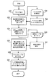
[0038]図4は符号化プロセスの一実施形態のフローチャートである。プロセスは、ハードウェア(たとえば、回路、専用ロジックなど)、(たとえば、汎用コンピュータシステム又は専用機械上で動かされる)ソフトウェア、又は、両者の組み合わせを備えるプロセシングロジックによって実行される。 [0038] FIG. 4 is a flowchart of one embodiment of an encoding process. The process is performed by processing logic comprising hardware (eg, circuitry, dedicated logic, etc.), software (eg, running on a general purpose computer system or a dedicated machine), or a combination of both.
[0039]図4を参照すると、プロセスは、プロシングロジックが複数の参照を使用して動き補償された予測を生成することにより開始し、ここで、各参照は、フィルタパラメータの組と1つずつ関連付けられている1つ以上の参照インデックスと関連付けられ、フィルタパラメータを用いて特有の参照インデックスと関連付けられているブロックが予測されたブロックを生成するためにフィルタ処理されている(処理ブロック401)。一実施形態では、動き補償された予測の生成は動き補償モジュールによって実行される。 [0039] Referring to FIG. 4, the process begins with the processing logic generating motion compensated predictions using multiple references, where each reference is one of a set of filter parameters and one. Blocks associated with one or more reference indexes that are associated with each other and associated with a specific reference index using filter parameters are filtered to produce a predicted block (processing block 401). . In one embodiment, the generation of motion compensated prediction is performed by a motion compensation module.
[0040]一実施形態では、参照内の各区分又はブロックは、異なる端数サンプル補間フィルタに対応する参照インデックスが割り当てられている。一実施形態では、フィルタパラメータの各組は補間フィルタに対応している。このような事例では、複数の参照が複数のフィルタに対応するフィルタパラメータの複数の組と関連付けられている。一実施形態では、補間フィルタは符号化された映像データ及び符号化された参照インデックスを収容するビットストリームを復号化する際に使用されるデコーダに知られている。別の実施形態では、補間フィルタは符号化された映像データ及び符号化された参照インデックスを収容するビットストリームを符号化する際に使用されるデコーダへ明示的に送られている。 [0040] In one embodiment, each partition or block in the reference is assigned a reference index corresponding to a different fractional sample interpolation filter. In one embodiment, each set of filter parameters corresponds to an interpolation filter. In such cases, multiple references are associated with multiple sets of filter parameters corresponding to multiple filters. In one embodiment, the interpolation filter is known to a decoder used in decoding a bitstream containing encoded video data and an encoded reference index. In another embodiment, the interpolation filter is explicitly sent to a decoder used in encoding the bitstream containing the encoded video data and the encoded reference index.
[0041]一実施形態では、フィルタは、{1,−5,20,20,−5,1}/32という形式のパラメータと関連付けられている1つ以上の6タップフィルタと、双一次補間フィルタと、双三次補間フィルタとを含む。別の実施形態では、フィルタは1つ以上の2Dフィルタを含む。 [0041] In one embodiment, the filter comprises one or more 6-tap filters associated with a parameter of the form {1, -5, 20, 20, -5, 1} / 32 and a bilinear interpolation filter. And a bicubic interpolation filter. In another embodiment, the filter includes one or more 2D filters.
[0042]一実施形態では、補間フィルタは、符号化された映像データ及び符号化された参照インデックスを収容するビットストリームを復号化する際に使用されるエンコーダとデコーダの両方に知られている。 [0042] In one embodiment, the interpolation filter is known to both the encoder and decoder used in decoding a bitstream containing encoded video data and an encoded reference index.
[0043]一実施形態では、フィルタリングパラメータはクロマ成分の組のためにも定義されている。あるクロマ成分のためのフィルタリングパラメータは、別のクロマ成分に基づいて決定されることがある。 [0043] In one embodiment, the filtering parameters are also defined for a set of chroma components. Filtering parameters for one chroma component may be determined based on another chroma component.
[0044]動き補償された予測を使用して、プロセシングロジックは、入力映像データと補償された予測との間の残差に対応するデータを含む映像データを符号化し(処理ブロック402)、符号化された映像データを伴うビットストリームの一部分である符号化された参照インデックスを生成するために参照インデックスを符号化する(処理ブロック403)。各インデックスはフィルタリングパラメータと関連付けられているので、符号化されたデータはデコーダへのフィルタリングパラメータを識別する。符号化演算は可変長エンコーダによって実行される。 [0044] Using motion compensated prediction, processing logic encodes video data that includes data corresponding to the residual between the input video data and the compensated prediction (processing block 402). The reference index is encoded to generate an encoded reference index that is a portion of the bitstream with the encoded video data (processing block 403). Since each index is associated with a filtering parameter, the encoded data identifies the filtering parameter to the decoder. The encoding operation is performed by a variable length encoder.
[0045]復号化演算は符号化演算の逆である。図5は復号化プロセスの一実施形態のフローチャートである。プロセスは、ハードウェア(たとえば、回路、専用ロジックなど)、(たとえば、汎用コンピュータシステム又は専用機械上で動かされる)ソフトウェア、又は、両者の組み合わせを備えるプロセシングロジックによって実行される。 [0045] The decoding operation is the reverse of the encoding operation. FIG. 5 is a flowchart of one embodiment of a decryption process. The process is performed by processing logic comprising hardware (eg, circuitry, dedicated logic, etc.), software (eg, running on a general purpose computer system or a dedicated machine), or a combination of both.
[0046]図5を参照すると、プロセスは、プロセシングロジックが入力映像データと動き補償された予測との間の差から生じる残差データに対応する符号化されたデータを含む符号化映像データを有するビットストリームを復号化することにより開始する(処理ロジック501)。一実施形態では、プロセシングロジックは動きベクトル及び参照インデックスをさらに復号化する。復号化演算は可変長デコーダによって実行されることがある。 [0046] Referring to FIG. 5, a process has encoded video data that includes encoded data corresponding to residual data resulting from the difference between input video data and motion compensated prediction processing logic. Start by decoding the bitstream (processing logic 501). In one embodiment, the processing logic further decodes the motion vector and reference index. The decoding operation may be performed by a variable length decoder.
[0047]次に、プロセシングロジックは、複数の参照を使用して動き補償された予測を生成し、ここで、各参照は、フィルタパラメータの組と1つずつが関連付けられている複数の参照インデックスと関連付けられ、フィルタパラメータを用いて特有の参照と関連付けられているブロックが端数サンプル位置を生成するためにフィルタ処理される(処理ブロック502)。一実施形態では、動き補償された予測の生成は、エンコーダ内の動き補償モジュール又はユニットによって実行される。 [0047] Next, processing logic generates motion compensated predictions using a plurality of references, where each reference is a plurality of reference indices associated with a set of filter parameters, one at a time. And the block associated with the unique reference using the filter parameters is filtered to generate a fractional sample position (processing block 502). In one embodiment, the generation of motion compensated prediction is performed by a motion compensation module or unit in the encoder.
[0048]その後、プロセシングロジックは、映像データを生成するために予測を残差データと合成する(処理ブロック503)。合成演算はデコーダ内の加算器によって実行される。 [0048] Processing logic then combines the prediction with the residual data to generate video data (processing block 503). The combining operation is performed by an adder in the decoder.
[0049]図6は補間プロセスの一実施形態の説明図である。図6を参照すると、適応フィルタは、1/2端数サンプル位置でサンプル値を生成するために使用されている。次に、別の適応双一次フィルタが1/4端数サンプル位置にサンプル値を生成するために1/2端数位置でサンプルをフィルタ処理する。補間フィルタ2はフィルタ1又は双一次と同じでもよい。しかし、フィルタ2はフィルタ1と全く異なることもある。このような事例では、付加的なシグナリングが必要とされる。
[0049] FIG. 6 is an illustration of one embodiment of an interpolation process. Referring to FIG. 6, the adaptive filter is used to generate sample values at 1/2 fractional sample positions. Next, another adaptive bilinear filter filters the samples at 1/2 fractional positions to produce sample values at 1/4 fractional sample positions. The
[0050]このような補間法を知らせ、かつ、利用する効果的な方策が本明細書に記載されている。 [0050] Effective strategies for informing and utilizing such interpolation methods are described herein.
シンタックスの実施例
[0051]H.264映像符号化規格は、参照記憶装置内の所与の参照を複数の参照インデックスと関連付ける柔軟性を提供する。参照ピクチャリスト並べ替えのための関連付けられたシンタックスは以下の表1に明らかにされている。

[0051] H. et al. The H.264 video coding standard provides the flexibility to associate a given reference in the reference store with multiple reference indexes. The associated syntax for reference picture list reordering is revealed in Table 1 below.
[0052]この性質は適応端数サンプル補間の枠組み内で利用されている。一実施形態では、このような補間はいつも役立つとは限らないので、補間が使用されているかどうかを示す単一のパラメータが上位レベルで(たとえば、ピクチャ内で、又は、コーデックの均等シーケンスパラメータセット内で)通知される。たとえば、H.264ピクチャパラメータセットRBSPシンタックスは、interpolated_pred_flagと呼ばれる付加的な要素を持ち込むことにより、表2のように修正される。この要素が存在しているならば、次に、下位のシンタックスレイヤにおいて、付加的な補間パラメータが伝送されてもよい。
[0053]一実施形態では、補間予測フラグがイネーブルであるならば、補間予測テーブル(pred_interpolation_table)が通知される。表3は所定の参照のため使用される補間フィルタ情報の全部を収容している。
[0054]表4における予測補間テーブルシンタックスは、あらゆる参照リスト(リスト0及びリスト1)内のあらゆる参照のための補間情報の全部を収容している。より詳細には、予測補間テーブルシンタックスは、補間フィルタのタイプ(luma_interpolation_lX_type)、このフィルタが(図6に示されているように)1/2画素位置だけのため適用され、双一次が1/4画素位置のため使用されるかどうか、又は、フィルタが全サンプル(luma_interpolation_lX_qpel)と、フィルタタップ数(luma_filter_length_IX又はluma_2Dfilter_length_IX)と、フィルタ精度(luma_filter_denom_IX及びluma_filter_2Ddenom_lX)と、実際のフィルタ係数(luma_filter_tap_lX及びluma_2Dfilter_coeffs_lX)のため適応されるかどうかを含むことがある。一実施形態では、フィルタ係数は可変長符号化されている(すなわち、ue(v))。別の実施形態では、フィルタ係数は固定長符号化されている(u(N)、すなわち、N=8)。さらに別の実施形態では、フィルタ係数値の予測は、たとえば、H.264デフォルト補間フィルタと対比して選択されるので、差分符号化が使用されるならば、フィルタ係数はより効率的に符号化されるであろう。 [0054] The predictive interpolation table syntax in Table 4 contains all of the interpolation information for every reference in every reference list (List 0 and List 1). More specifically, the predictive interpolation table syntax is applied because of the type of interpolation filter (luma_interpolation_lX_type), this filter is only for 1/2 pixel position (as shown in FIG. 6), and bilinear is 1 / 4 whether used for pixel position, or filter the entire sample (luma_interpolation_lX_qpel), the number of filter taps and (Luma_filter_length_IX or Luma_2Dfilter_length_IX), and filter accuracy (Luma_filter_denom_IX and Luma_filter_2Ddenom_lX), actual filter coefficients (Luma_filter_tap_lX and Luma_2Dfilter_coeffs_lX) It may include whether adapted for. In one embodiment, the filter coefficients are variable length coded (ie ue (v)). In another embodiment, the filter coefficients are fixed length encoded (u (N), ie N = 8). In yet another embodiment, the prediction of filter coefficient values may be performed by, for example, H.264. Since it is selected in contrast to the H.264 default interpolation filter, the filter coefficients will be encoded more efficiently if differential encoding is used.
[0055]同様のシンタックスが両方のリストのため存在するが、利用可能であるならば(たとえば、モノクロシーケンスを示唆するchroma_fomat_idcが0でないならば)、クロマ成分のためにも存在する。双予測補間フィルタを単一予測補間フィルタから分離する付加的な要素が存在する可能性もあるが、並べ替えシンタックスを通じて再びこの挙動をエミュレートすることも可能であり(すなわち、同じ参照が2つの異なる参照インデックスと関連付けられ)、一方が単一予測補間フィルタと関連付けられ、双予測重みがもう一方と関連付けられる。
[0056]上記表の1つの要素はフィルタタイプ(すなわち、luma_interpolation_lX_type)である。この要素は、広範囲の可能な補間フィルタのうちの1つを示している。広範囲の補間フィルタを指定可能であることは、実行される補間に関して付加的な柔軟性を提供する。一実施形態では、ルマに対し、使用される補間メカニズムは以下の表5に記載されている。
[0057]同様の検討がクロマに対して行われ得るが、一実施形態では、両方のコンポーネントが異なる補間メカニズム又は同じ補間メカニズムを使用することを指定する(すなわち、このことがchroma_interpolation_lX_typeを使用して第2の成分のため通知される)。別の実施形態では、クロマのためより適している他のフィルタが、特に、補間は1/8画素レベルに至るまで行われることに重点を置いて使用される。たとえば、一実施形態では、第1のクロマ成分のため、chroma_interpolation_lX_typeのセマンティックが表6に与えられている。
一方、第2の成分に対し、chroma_interpolation_lX_type[i][1]=0は、第1の成分のフィルタが再使用されていることを示している。一実施形態では、割り当てが表1に与えられ、又は、可能であれば、1番目のエントリーに基づいて表を適応させる。
On the other hand, chroma_interpolation_lX_type [i] [1] = 0 for the second component indicates that the filter of the first component is reused. In one embodiment, the assignment is given in Table 1, or adapts the table based on the first entry if possible.
代替的な実施形態
[0058]一実施形態では、本明細書に記載されている技術は、重み付き予測パラメータを知らせる代替的な方法を提供する。この方法は、H.264のようなコーデックによってサポートされている既存の重み付きパラメータと組み合わせることがさらに可能であり(すなわち、同様に暗黙的な重み付け、並びに、適応補間フィルタの使用)、動き補償された予測の点でさらなる柔軟性及び改善された効率を提供する。エンコーダ及びデコーダの基本構造は従来型のエンコーダ及びデコーダに依然として類似している(図7及び8)。
Alternative embodiments
[0058] In one embodiment, the techniques described herein provide an alternative way of signaling weighted prediction parameters. This method is described in H.H. It is further possible to combine with existing weighted parameters supported by codecs like H.264 (ie also using implicit weighting as well as adaptive interpolation filters) and in terms of motion compensated prediction Provides additional flexibility and improved efficiency. The basic structure of the encoder and decoder is still similar to the conventional encoder and decoder (FIGS. 7 and 8).
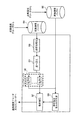
[0059]図7はエンコーダの一実施形態のブロック図である。一実施形態では、コーダは、最初に入力ビットストリームを、マクロブロックと呼ばれる、矩形状配列に分割する。マクロブロック毎に、エンコーダは、次に、イントラフレーム符号化を使用すべきか、又は、インターフレーム符号化を使用すべきかを選択する。イントラフレーム符号化は、現在の映像フレームに収容されている情報だけを使用し、Iフレームと呼ばれる圧縮結果を作成する。イントラフレーム符号化は、現在フレームの前後に出現する1つ以上の他のフレームの情報を使用可能である。前フレームからのデータだけを使用する圧縮結果はPフレームと呼ばれ、現在フレームの前及び後の両方からのデータを使用する圧縮結果はBフレームと呼ばれる。 [0059] FIG. 7 is a block diagram of one embodiment of an encoder. In one embodiment, the coder first divides the input bitstream into rectangular arrays called macroblocks. For each macroblock, the encoder then selects whether to use intraframe coding or interframe coding. Intra-frame coding uses only the information contained in the current video frame and creates a compression result called an I frame. Intra-frame coding can use information of one or more other frames that appear before and after the current frame. A compression result using only data from the previous frame is called a P frame, and a compression result using data from both before and after the current frame is called a B frame.
[0060]図7を参照すると、映像701はエンコーダへ入力される。動き補償無しでフレームを符号化する事例では、映像のフレームはDCT703へ入力される。DCT703は、DCT係数を作成するために2次元離散コサイン変換(DCT)を実行する。係数は量子化器704によって量子化される。一実施形態では、量子化器704によって実行される量子化は、スケーラーQPによって重み付けされる。一実施形態では、量子化器スケーラーパラメータQPは1から31までの値をとる。QP値はピクチャレベルとマクロブロックレベルの両方で修正されても構わない。
[0060] Referring to FIG. 7,
[0061]その後、量子化された係数は、ビットストリーム720を生成するVLC705で可変長符号化を受ける。一実施形態では、VLC705は、ハフマン符号化のようなエントロピー符号化段においてトリプレット(ラスト、ラン、レベル)を表現するために1つのシンボルを使用することによりエントロピー符号化を実行する。
[0061] The quantized coefficients are then subjected to variable length coding in the
[0062]注意すべき点は、一実施形態では、VLC705より前に、並べ替えが実行され、量子化されたDCT係数は、係数の2次元配列が当分野において周知の方法で係数の1次元アレイに変換されるようにジグザグ走査されることである。並べ替えの後に、各ブロックに対応する並べ替え後の量子化された係数の配列が零係数をより良く表現するために符号化されるランレングス符号化が続けられる。このような事例では、各非零係数はトリプレット(ラスト、ラン、レベル)として符号化され、ここで、「ラスト」は係数がブロックにおける最終的な非零係数であるかどうかを示し、「ラン」は先行する0係数を示し、「レベル」は係数の符号及び大きさを示している。
[0062] It should be noted that, in one embodiment, prior to
[0063]フレームのコピーは参照フレームとして使用するため確保されている。このことはIフレーム又はPフレームの場合に特にこのような状況である。そのためには、量子化器704から出力された量子化された係数は、逆量子化器706によって逆量子化される。逆DCT変換はIDCT707を使用して逆量子化された係数に適用される。結果として得られるフレームデータは、Pフレームの事例では動き補償(MC)ユニット709からの動き補償された予測に加算され、次に、結果として得られたフレームがループフィルタ712を使用してフィルタ処理され、参照フレームとしての使用のためフレームバッファ711に格納される。Iフレームの事例では、IDCT707から出力されたデータは、MCユニット709からの動き補償予測に加算され、ループフィルタ712を使用してフィルタ処理され、フレームバッファ711に格納される。
[0063] A copy of the frame is reserved for use as a reference frame. This is especially the case for I-frames or P-frames. For this purpose, the quantized coefficient output from the
[0064]Pフレームの事例では、Pフレームは、技術的には一般的に参照フレームと呼ばれている前のIフレーム又はPフレームからのインター予測を用いて符号化される。この事例では、インター予測は、動き推定(ME)ブロック710及び動き補償ユニット709によって実行される。この事例では、フレーム記憶装置711及び入力映像701からの参照フレームを使用して、動き推定種ニット710は、現在フレーム内の現在マクロブロックと最も良く一致した参照フレーム内の領域の場所を探索する。動き推定ユニット710のための動きベクトルは動き補償ユニット709へ送られる。動き補償ユニット709で、残差マクロブロックを生成するために減算器702を使用して、予測が現在マクロブロックから減算される。残差はその後に、上述されているようにDCT703、量子化器704及びVLC705を使用して符号化される。
[0064] In the case of P frames, P frames are encoded using inter prediction from previous I frames or P frames, which are commonly referred to in the art as reference frames. In this case, inter prediction is performed by motion estimation (ME) block 710 and
[0065]動き推定ユニット710は、重み付きパラメータを可変長符号化705のためのVLC705へ出力する。VLC705の出力はビットストリーム720である。
[0065]
[0066]図8はデコーダの一実施形態のブロック図である。図8を参照すると、ビットストリーム801は、可変長復号化を実行する可変長デコーダ802によって受信される。可変長復号化の出力は、量子化器704によって実行される量子化の反対である逆量子化演算を実行する逆量子化器803へ送られる。逆量子化器803の出力は、画像データを生成するためにIDCT804によって逆DCT変換された係数からなる。Iフレームの事例では、IDCT804の出力はループフィルタ821によってフィルタ処理され、フレームバッファ822に格納され、最終的に出力860として出力される。Pフレームの事例では、IDCT804から出力された画像データは、加算器805を使用して動き補償ユニット810からの予測に加算される。動き補償ユニット810は、上述されている重み付きパラメータを含む可変長デコーダ822からの出力と、フレームバッファ822からの参照フレームとを使用する。加算器805から出力される結果として得られる画像データは、ループフィルタ821を使用してフィルタ処理され、出力860の一部として最終的な出力のためフレームバッファ822に格納される。
[0066] FIG. 8 is a block diagram of one embodiment of a decoder. Referring to FIG. 8, a
[0067]しかし、この場合には、単一の補間メカニズムだけでなく異なる/複数の補間メカニズムを考慮するので、参照リストがどのように取り扱われるかと、動き推定及び補償のプロセスがどのように実行されるかに関して重要な相違点が存在する。図9は、エンコーダ及び/又はデコーダの一部として参照リスト使用法への影響を説明している。参照は最初に系統立てられ、動き推定及び動き補償を考慮する前に処理される。 [0067] However, in this case, not only a single interpolation mechanism but also different / multiple interpolation mechanisms are considered, so how the reference list is handled and how the motion estimation and compensation process is performed. There are important differences as to what is done. FIG. 9 illustrates the impact on reference list usage as part of an encoder and / or decoder. The references are first organized and processed before considering motion estimation and motion compensation.
[0068]図9を参照すると、参照ピクチャがメモリ901に記憶されている。参照ピクチャはエンコーダ又はデコーダから受信される。リスト0及びリスト1はメモリ901に記憶されている参照ピクチャを使用して初期化される。一実施形態では、実行される初期化は、当分野において周知のH.264規格の初期化である。注意すべき点は、リスト1はBスライスが動き推定及び補償に使用されるときに初期化されることである。初期化後、リスト0及びリスト1内の参照は、それぞれ、並べ替えモジュール904及び905を使用して並べ替えられる。一実施形態では、並べ替えは、最も頻繁に使用される参照インデックスがリストの先頭に来るように実行される。同様に、この並べ替えはH.264規格に準じて実行され、当分野において周知である。並べ替え後に、並べ替えリスト0内の各参照に一連の関数907が適用される。関数906及び907から結果として得られる出力は動き推定モジュール908及び動き補償モジュール909へ送られる。(本明細書の目的のため、モジュールはハードウェアでも、ソフトウェアでも、ファームウェアでも、全ての組み合わせでも構わないことに注意すべきである。)動き補償モジュール909は、エンコーダ及びデコーダのための生成された動き補償予測を実行するために、これらの関数906及び907の出力を、動き推定モジュール908の出力と共に使用する。デコーダに関しては、動き情報がビットストリームから直接的に入手可能であるので、動き推定エレメントがデコーダに含まれていないことに注意すべきである。
[0068] Referring to FIG. 9, reference pictures are stored in
[0069]一実施形態では、本明細書に詳述されている技術が空間スケーラブル映像符号化に適用される。このような事例では、この技術は、基底低解像度レイヤを補間する単一のメカニズムを指定するのではなく、現在の高解像度レイヤを予測するため使用され、並べ替えコマンドを使用する補間法の完全な組を所定の低解像度参照に割り当てる。これにより参照ピクチャの新しい組が生成され、各参照ピクチャは異なる参照インデックス及び補間フィルタと関連付けられている。ブロックレベルでは、参照インデックスはこの場合も、付加的なオーバーヘッドを全く必要とすることなくアップサンプリングのため使用される補間法を示している。 [0069] In one embodiment, the techniques detailed herein are applied to spatial scalable video coding. In such cases, this technique is used to predict the current high resolution layer, rather than specifying a single mechanism to interpolate the base low resolution layer, and is a complete interpolation method that uses the sort command. Assign a set to a given low resolution reference. This creates a new set of reference pictures, each reference picture being associated with a different reference index and interpolation filter. At the block level, the reference index again indicates the interpolation method used for upsampling without requiring any additional overhead.
[0070]図12は空間スケーラビリティのための適応補間を説明する図である。図12を参照すると、低解像度バッファ1201は低解像度デコーダ(図示せず)からレイヤを受信する。高解像度バッファは高解像度デコーダ(図示せず)から高解像度レイヤを受信する。低解像度バッファ1201からの低解像度レイヤは、参照初期化モジュール1203内で参照を初期化するため使用される。並べ替えモジュール1204は、並べ替えコマンドを使用して補間法の組を参照に割り当てる。一実施形態では、この割り当てはH.264規格に記述されているように行われる。その後に、並べ替えモジュール1204から出力されたレイヤがアップサンプラ1205を使用してアップサンプリングされる。アップサンプラ1205は、関数の組g0,0(x,y)−g0,n(x,y)を適用する。低解像度の基底レイヤは補間され、高解像度の現在レイヤを予測するために、動き推定モジュール1206と連動して動き補償モジュール1207によって使用される。動き補償予測は高解像度デコーダ(又はエンコーダ)へ送られる。
[0070] FIG. 12 is a diagram illustrating adaptive interpolation for spatial scalability. Referring to FIG. 12, the
[0071]補間フィルタは、マルチパス法を実行することにより、又は、符号化されるべき内容のある特性を考慮することにより選択される。一実施形態では、初期的な移動ベクトルの組の推定は初期フィルタを使用して行われる。次に、フィルタ係数が、これらの移動ベクトルを使用して動き補償された予測を実行するときに、予測誤差のエネルギーを最小化(又は低減)することによりブロック毎に推定される。フィルタは、その後に、ヒストグラムアプローチに基づいて分類され、必要に応じて精緻化され、その後に、最良Nフィルタがシグナリング及び最終的な符号化のため選択される。図10Aは、補間パラメータを決定するプロセスの一実施形態のフローチャートである。プロセスは、ハードウェア(たとえば、回路、専用ロジックなど)、(たとえば、汎用コンピュータシステム又は専用機械上で動かされる)ソフトウェア、又は、両者の組み合わせを備えるプロセシングロジックによって実行される。 [0071] The interpolation filter is selected by performing a multi-pass method or by considering certain characteristics of the content to be encoded. In one embodiment, the initial set of motion vectors is estimated using an initial filter. The filter coefficients are then estimated for each block by minimizing (or reducing) the energy of the prediction error when performing motion compensated prediction using these motion vectors. The filters are then classified based on a histogram approach and refined as necessary, after which the best N filter is selected for signaling and final coding. FIG. 10A is a flowchart of one embodiment of a process for determining interpolation parameters. The process is performed by processing logic comprising hardware (eg, circuitry, dedicated logic, etc.), software (eg, running on a general purpose computer system or a dedicated machine), or a combination of both.
[0072]図10Aを参照すると、プロセスは、プロセシングロジックがフィルタ統計量を初期化することにより開始する(処理ブロック1001)。一実施形態では、フィルタ統計量を初期化するステップは、ヒストグラム(HISTINT)を初期化するステップを含む。一実施形態では、統計量は、各フィルタが選択された回数を明らかにする。次に、プロセシングロジックはループに入る(処理ブロック1002)。ループ内で、プロセシングロジックはバッファ内の参照毎にデフォルト補間フィルタを設定し(処理ブロック1003)、ブロック毎に、プロセシングロジックが動き推定を実行する別のループに入り(処理ブロック1005)、最良動きベクトルを使用して補間フィルタを精緻化し(処理ブロック1006)、ヒストグラムHISTINT内の補間統計量を更新する(処理ブロック1007)。動き推定への結果は、最良動きベクトル(MVbest)が突き止められることである。 [0072] Referring to FIG. 10A, the process begins with processing logic initializing filter statistics (processing block 1001). In one embodiment, initializing the filter statistic includes initializing a histogram (HIST INT ). In one embodiment, the statistics reveal the number of times each filter has been selected. Next, processing logic enters a loop (processing block 1002). Within the loop, processing logic sets a default interpolation filter for each reference in the buffer (processing block 1003), and for each block, the processing logic enters another loop that performs motion estimation (processing block 1005), and the best motion. The vector is used to refine the interpolation filter (processing block 1006) and the interpolation statistics in the histogram HIST INT are updated (processing block 1007). The result to motion estimation is that the best motion vector (MV best ) is located.
[0073]バッファ内の参照毎に各ブロックを処理した後、プロセシングロジックは処理ブロック1010へ移り、プロセシングロジックは全ての参照に対する最良フィルタを決定するために統計量を解析する。一実施形態では、プロセシングロジックは、全ての参照に対する最良フィルタを決定するためにHISTINTを調べる。次に、プロセシングロジックは補間フィルタを固定することによりフレームを再符号化する(処理ブロック1011)。一実施形態では、フレームを再符号化するプロセスの一部として、プロセシングロジックは動き推定及び参照を精緻化する。その後に、プロセスは終了する。
[0073] After processing each block for each reference in the buffer, processing logic moves to
[0074]より低い複雑性コストをさらに有する代替的な実施形態では、動き推定はあらゆる参照を考慮してあらゆるブロックに対して実行される。あらゆる参照からの最良動きベクトルを使用して、その参照のための最良補間フィルタもまた見つけられる。しかし、最良参照からのパラメータだけが考慮され、その間に、他の全ての参照が廃棄され、要求され得る余分な処理を回避する。図10Bは補間パラメータを決定する代替的な実施形態のフローチャートである。プロセスは、ハードウェア(たとえば、回路、専用ロジックなど)、(たとえば、汎用コンピュータシステム又は専用機械上で動かされる)ソフトウェア、又は、両者の組み合わせを備えるプロセシングロジックによって実行される。 [0074] In an alternative embodiment that further has a lower complexity cost, motion estimation is performed for every block taking into account any references. Using the best motion vector from any reference, the best interpolation filter for that reference is also found. However, only the parameters from the best reference are considered, during which all other references are discarded, avoiding extra processing that may be required. FIG. 10B is a flowchart of an alternative embodiment for determining interpolation parameters. The process is performed by processing logic comprising hardware (eg, circuitry, dedicated logic, etc.), software (eg, running on a general purpose computer system or a dedicated machine), or a combination of both.
[0075]図10Bを参照すると、プロセスは、各ブロックが処理されるループで開始する(処理ブロック1020)。ループ内では、プロセシングロジックは、別の内側ループを処理し始め(処理ブロック1021)、ループ内で、バッファ内の参照毎に、プロセシングロジックがデフォルト補間フィルタを設定し(処理ブロック1022)、最良動きベクトル(MVbest)を見つけるために動き推定を実行し(処理ブロック1024)、最良ベクトル(MVbest)を使用して補間フィルタを精緻化する(処理ブロック1024)。バッファ内の全参照が処理されると、内側ループが終了する。 [0075] Referring to FIG. 10B, the process begins with a loop in which each block is processed (processing block 1020). Within the loop, processing logic begins processing another inner loop (processing block 1021), and within the loop, for each reference in the buffer, processing logic sets a default interpolation filter (processing block 1022) and performs best. Motion estimation is performed to find the vector (MV best ) (processing block 1024), and the interpolation vector is refined using the best vector (MV best ) (processing block 1024). When all the references in the buffer have been processed, the inner loop ends.
[0076]その後に、処理は外側ループに引き継がれ、プロセシングロジックは最良参照を選択し(処理ブロック1027)、最良参照からの統計量に基づいてHISTINT内の補間統計量を更新する(処理ブロック1026)。外側ループは、各ブロックが処理されるまで継続し、その後、外側ループは終了する(処理ブロック1028)。各ブロックが処理されると、プロセシングロジックはヘッダ情報を更新し、ビットストリームを符号化及び/又は書き込む(処理ブロック1029)。 [0076] Thereafter, processing is passed to the outer loop and processing logic selects the best reference (processing block 1027) and updates the interpolated statistics in the HIST INT based on the statistics from the best reference (processing block). 1026). The outer loop continues until each block is processed, after which the outer loop ends (processing block 1028). As each block is processed, processing logic updates the header information and encodes and / or writes the bitstream (processing block 1029).
[0077]補間フィルタへのさらなる制約(すなわち、参照1つ当たりに許容されるフィルタの最大数、導入された新しいフィルタ毎のペナルティーの考慮など)がさらに課され、制約は最良フィルタを決定するという点で役立つ。デコーダ端では、参照インデックスに基づいて補間フィルタが直ちに決定され、他の復号化プロセスに全く影響を与えることなく補間が実行される。 [0077] Further constraints on the interpolation filter (ie, the maximum number of filters allowed per reference, consideration of penalties for each new filter introduced, etc.) are further imposed, and the constraints determine the best filter. Useful in terms. At the decoder end, the interpolation filter is immediately determined based on the reference index, and the interpolation is performed without affecting the other decoding processes at all.
[0078]図11はデコーダによって実行される補間選択性プロセスの一実施形態のフローチャートである。プロセスは、ハードウェア(たとえば、回路、専用ロジックなど)、(たとえば、汎用コンピュータシステム又は専用機械上で動かされる)ソフトウェア、又は、両者の組み合わせを備えるプロセシングロジックによって実行される。 [0078] FIG. 11 is a flowchart of one embodiment of an interpolation selectivity process performed by a decoder. The process is performed by processing logic comprising hardware (eg, circuitry, dedicated logic, etc.), software (eg, running on a general purpose computer system or a dedicated machine), or a combination of both.
[0078]図11を参照すると、プロセスは、並べ替え情報、重み付けパラメータ情報及び補間情報を含むスライス情報を復号化することにより開始する(処理ブロック1101)。一実施形態では、並べ替え情報は並べ替えコマンドからなる。スライス情報を復号化した後、プロセシングロジックは参照リストを作成する(処理ブロック1102)。次に、プロセシングロジックはブロック毎にループを実行し(処理ブロック1103)、ループ内で、プロセシングロジックはリストi毎に参照インデックスriを復号化し(処理ブロック1104)、動きベクトル及び重み付けパラメータを含む動き情報を復号化し(処理ブロック1105)、r0及びr1に基づいて補間フィルタを選択し(処理ブロック1106)、選択されたフィルタ及び動きベクトルパラメータを使用して動き補償を実行する(処理ブロック1107)。その後に、ループは終了する(処理ブロック1108)。ループが終了した後、プロセスが終了する。 [0078] Referring to FIG. 11, the process begins by decoding slice information including reordering information, weighting parameter information, and interpolation information (processing block 1101). In one embodiment, the reordering information comprises a reordering command. After decoding the slice information, processing logic creates a reference list (processing block 1102). Next, the processing logic performs a loop for each block (processing block 1103), and within the loop, the processing logic decodes the reference index r i for each list i (processing block 1104) and includes a motion vector and a weighting parameter. The motion information is decoded (processing block 1105), an interpolation filter is selected based on r 0 and r 1 (processing block 1106), and motion compensation is performed using the selected filter and motion vector parameters (processing block). 1107). Thereafter, the loop ends (processing block 1108). After the loop ends, the process ends.
[0080]適応端数サンプル補間が動き補償された映像符号化にさらに役立つように明らかにされている。本明細書に記載されている技術は、H.264のようなある種の映像符号化規格に提供されている並べ替えメカニズムの巧く利用することにより、このような適応端数サンプル補間メカニズムを効率的に考慮し表現し、シーケンスの局所特性がエイリアシングの観点で変化するときに、符号化効率を(すなわち、所定のビットレートに対するPSNRを増加させるという点で)高め、そして、空間スケーラブル映像符号化アーキテクチャの符号化効率を高めるために使用されている。 [0080] Adaptive fractional sample interpolation has been clarified to further aid in motion compensated video coding. The techniques described herein are described in H.C. By taking advantage of the reordering mechanism provided in certain video coding standards such as H.264, this adaptive fractional sample interpolation mechanism is efficiently considered and expressed, and the local characteristics of the sequence are aliased. Is used to increase the coding efficiency (ie in terms of increasing the PSNR for a given bit rate) and to increase the coding efficiency of the spatial scalable video coding architecture. .
コンピュータシステムの実施例
[0081]図13は、本明細書に記載されている1つ以上の動作を実行する例示的なコンピュータシステムのブロック図である。図13を参照すると、コンピュータシステム1300は、例示的なクライアント又はサーバーコンピュータシステムを備える。コンピュータシステム1300は、情報を通信する通信メカニズム又はバス1311と、バス1311と接続され、情報を処理するプロセッサ1312とを備える。プロセッサ1312は、たとえば、Pentium(商標)、PowerPC(商標)、Alpha(商標)などのようなマイクロプロセッサを含むが、マイクロプロセッサには限定されない。
Example of a computer system
[0081] FIG. 13 is a block diagram of an exemplary computer system that performs one or more operations described herein. With reference to FIG. 13, a
[0082]システム1300は、バス1311に接続され、情報及びプロセッサ1312によって実行されるべき命令を記憶するランダムアクセスメモリ(RAM)、又は、その他のダイナミック記憶装置1304(主メモリと呼ばれる)をさらに備える。主メモリ1304は、プロセッサ1312による命令の実行中に、一時変数又はその他の中間情報を記憶するためにも使用される。
[0082] The
[0083]コンピュータシステム1300は、バス1311に接続され、静的情報及びプロセッサ1312のための命令を記憶するリードオンリーメモリ(ROM)及び/又はその他のスタティック記憶装置1306と、磁気ディスク又は光ディスク及びこれらのディスクに対応するディスクドライブのようなデータ記憶装置1307とをさらに備える。データ記憶装置1307はバス1311に接続され、情報及び命令を記憶する。
[0083] The
[0084]コンピュータシステム1300は、バス1311に接続され情報をコンピュータユーザへ提示する陰極線管(CRT)又は液晶ディスプレイ(LCD)のような表示装置1321にさらに接続されている。英数字キー及びその他のキーを含む英数字入力装置1322もまたバス1311に接続され、情報及びコマンド選択をプロセッサ1312へ通信する。付加的なユーザ入力装置は、バス1311に接続され、方向情報及びコマンド選択をプロセッサへ通信し、ディスプレイ1321上のカーソル移動を制御するマウス、トラックボール、トラックパッド、スタイラス、又は、カーソル方向キーのようなカーソル制御装置1323である。
[0084] The
[0085]バス1311に接続される別の装置は、紙、フィルム、又は、同様のタイプの媒体のような媒体上に情報を記録するハードコピー装置1324である。バス1311に接続される別の装置は、電話機又はハンドヘルド式パーム型装置へ通信するための有線/無線通信機能装置1325である。 [0085] Another device connected to the bus 1311 is a hard copy device 1324 that records information on media such as paper, film, or similar types of media. Another device connected to the bus 1311 is a wired / wireless communication function device 1325 for communicating to a telephone or handheld palm type device.
[0086]システム1300の何れか又は全部のコンポーネント、及び、関連したハードウェアが本発明において使用されることに注意すべきである。しかし、コンピュータシステムのその他の構造は装置の一部又は全部を含むことがわかる。
[0086] It should be noted that any or all components of
[0087]本発明の多数の代替及び変更は、おそらく上記の説明を読んだ後に当業者に明白になるが、例示のために図示され記載された特有の実施形態が制限的であるとみなされることは決して意図されていないことが理解されるべきである。したがって、様々な実施形態の細部への言及は、発明に不可欠であると考えられる特徴だけを本質的に列挙している請求項の範囲を制限することを目的としていない。 [0087] Numerous alternatives and modifications of the present invention will probably become apparent to those skilled in the art after reading the above description, but the specific embodiments illustrated and described for purposes of illustration are considered limiting. It should be understood that this is never intended. Accordingly, references to details of various embodiments are not intended to limit the scope of the claims that merely list only those features that are considered essential to the invention.
Claims (26)
入力映像データと前記動き補償モジュールからの補償された予測との間の残差に対応するデータを含む映像データを符号化するコーダと、を備えるビデオエンコーダ。 Each one of the two or more references is associated with two or more reference indexes, and each one of the plurality of reference indexes is associated with a set of filter parameters and associated with the reference index. A motion compensation module that generates the predicted block of motion compensated prediction using the two or more references, wherein the block is filtered with the filter parameter to generate a predicted block When,
A coder that encodes video data including data corresponding to a residual between input video data and the compensated prediction from the motion compensation module.
入力映像データと動き補償モジュールからの補償された予測との間の残差に対応するデータを含む映像データを符号化するステップと、を備える符号化方法。 Each reference of the plurality of references is associated with a plurality of reference indices, each one of the plurality of reference indices is associated with a set of filter parameters, and the block associated with each reference is a fractional sample position Generating a motion-compensated prediction prediction block using the plurality of references filtered using the filter parameters to generate
Encoding video data including data corresponding to the residual between the input video data and the compensated prediction from the motion compensation module.
複数の参照のうちの各参照が複数の参照インデックスと関連付けられ、前記複数の参照インデックスのうちの1つずつがフィルタパラメータの組と関連付けられ、前記各参照と関連付けられているブロックが端数サンプル位置を生成するために前記フィルタパラメータを用いてフィルタ処理される、前記複数の参照を使用して、動き補償された予測の予測ブロックを生成するステップと、
入力映像データと動き補償モジュールからの補償された予測との間の残差に対応するデータを含む映像データを符号化するステップと、を備える符号化方法を前記システムに実行させる命令を記憶する1つ以上の読み取り可能な媒体。 When executed by the system
Each reference of the plurality of references is associated with a plurality of reference indices, each one of the plurality of reference indices is associated with a set of filter parameters, and the block associated with each reference is a fractional sample position Generating a motion-compensated prediction prediction block using the plurality of references filtered using the filter parameters to generate
Storing instructions for causing the system to execute an encoding method comprising: encoding video data including data corresponding to a residual between input video data and a compensated prediction from a motion compensation module; One or more readable media.
各参照インデックスは、所定の形式のフィルタパラメータを有するフィルタに関連付けられており、前記参照インデックスに従って参照フレーム及び複数のフィルタのうちの1つを選択し、前記選択されたフィルタが予測されたブロックを獲得するため動きベクトルによって決定された前記参照フレームのサンプルの組をフィルタ処理する動き補償モジュールと、を備える装置。 A decoder for decoding the reference index and the motion vector;
Each reference index is associated with a filter having a predetermined type of filter parameter, and selects a reference frame and one of a plurality of filters according to the reference index, and the selected filter selects a predicted block. A motion compensation module for filtering the set of reference frame samples determined by the motion vector to obtain.
参照インデックスを復号化するステップと、
動きベクトルを復号化するステップと、
前記参照インデックスに従って参照フレームを選択するステップと、
各参照インデックスは、所定の形式のフィルタパラメータを有するフィルタに関連付けられており、前記参照インデックスに従ってフィルタを選択するステップと、
前記予測されたブロックを獲得するために前記フィルタを使用して、前記動きベクトルにより決定された前記参照フレームのサンプルの組をフィルタ処理するステップと、を備える方法。 A method for generating a predicted block in a video decoder, comprising:
Decrypting the reference index;
Decoding a motion vector;
Selecting a reference frame according to the reference index;
Each reference index is associated with a filter having a predetermined type of filter parameter, and selecting a filter according to the reference index;
Filtering the set of reference frame samples determined by the motion vector using the filter to obtain the predicted block.
参照インデックスを復号化するステップと、
動きベクトルを復号化するステップと、
前記参照インデックスに従って参照フレームを選択するステップと、
各参照インデックスは、所定の形式のフィルタパラメータを有するフィルタに関連付けられており、前記参照インデックスに従ってフィルタを選択するステップと、
予測されたブロックを獲得するために前記フィルタを使用して、前記動きベクトルにより決定された前記参照フレームのサンプルの組をフィルタ処理するステップと、を備える予測されたブロックを生成する方法を前記システムに実行させる命令を記憶する1つ以上の読み取り可能な媒体。 When executed by the system
Decrypting the reference index;
Decoding a motion vector;
Selecting a reference frame according to the reference index;
Each reference index is associated with a filter having a predetermined type of filter parameter, and selecting a filter according to the reference index;
Filtering the set of samples of the reference frame determined by the motion vector using the filter to obtain a predicted block, the method comprising: generating a predicted block comprising: One or more readable media that store instructions to be executed by the computer.
第1の参照インデックス及び第2の参照インデックスを復号化するステップと、
第1の動きベクトル及び第2の動きベクトルを復号化するステップと、
前記第1の参照インデックスに応じて第1の参照フレームを選択し、前記第2の参照インデックスに従って第2の参照フレームを選択するステップと、
各第1の参照インデックスは第1のフィルタパラメータを有する第1のフィルタに、各第2の参照インデックスは第2のフィルタパラメータを有する第2のフィルタに、それぞれ関連付けられており、前記第1の参照インデックスに応じて第1のフィルタを選択し、前記第2の参照インデックスに従って第2のフィルタを選択するステップと、
第1のブロックを獲得するために前記第1のフィルタを使用して、前記第1の動きベクトルにより決定された前記第1の参照フレームの第1のサンプルの組をフィルタ処理するステップと、
第2のブロックを獲得するために前記第2のフィルタを使用して、前記第2の動きベクトルにより決定された前記第2の参照フレームの第2のサンプルの組をフィルタ処理するステップと、
を備える方法。 A method for generating a predicted block in a video decoder, comprising:
Decoding a first reference index and a second reference index;
Decoding the first motion vector and the second motion vector;
Selecting a first reference frame according to the first reference index and selecting a second reference frame according to the second reference index;
Each first reference index is associated with a first filter having a first filter parameter, and each second reference index is associated with a second filter having a second filter parameter. Selecting a first filter according to a reference index and selecting a second filter according to the second reference index;
Filtering the first set of samples of the first reference frame determined by the first motion vector using the first filter to obtain a first block;
Filtering the second set of samples of the second reference frame determined by the second motion vector using the second filter to obtain a second block;
A method comprising:
Applications Claiming Priority (5)
| Application Number | Priority Date | Filing Date | Title |
|---|---|---|---|
| US69357505P | 2005-06-24 | 2005-06-24 | |
| US60/693,575 | 2005-06-24 | ||
| US11/452,043 | 2006-06-12 | ||
| US11/452,043 US8208564B2 (en) | 2005-06-24 | 2006-06-12 | Method and apparatus for video encoding and decoding using adaptive interpolation |
| PCT/US2006/024528 WO2007002437A2 (en) | 2005-06-24 | 2006-06-23 | Method and apparatus for video encoding and decoding using adaptive interpolation |
Publications (2)
| Publication Number | Publication Date |
|---|---|
| JP2008544708A JP2008544708A (en) | 2008-12-04 |
| JP5378791B2 true JP5378791B2 (en) | 2013-12-25 |
Family
ID=37307409
Family Applications (1)
| Application Number | Title | Priority Date | Filing Date |
|---|---|---|---|
| JP2008518451A Active JP5378791B2 (en) | 2005-06-24 | 2006-06-23 | Method and apparatus for video encoding and decoding using adaptive interpolation |
Country Status (5)
| Country | Link |
|---|---|
| US (1) | US8208564B2 (en) |
| EP (1) | EP1894418A2 (en) |
| JP (1) | JP5378791B2 (en) |
| CN (1) | CN101208957B (en) |
| WO (1) | WO2007002437A2 (en) |
Cited By (1)
| Publication number | Priority date | Publication date | Assignee | Title |
|---|---|---|---|---|
| KR20170125297A (en) * | 2016-05-04 | 2017-11-14 | 한국항공대학교산학협력단 | Method and apparatus for coding image compensation information and decoding using the same |
Families Citing this family (129)
| Publication number | Priority date | Publication date | Assignee | Title |
|---|---|---|---|---|
| US7609765B2 (en) | 2004-12-02 | 2009-10-27 | Intel Corporation | Fast multi-frame motion estimation with adaptive search strategies |
| CN1859576A (en) * | 2005-10-11 | 2006-11-08 | 华为技术有限公司 | Top sampling method and its system for space layered coding video image |
| CN1794821A (en) * | 2006-01-11 | 2006-06-28 | 浙江大学 | Method and device of interpolation in grading video compression |
| EP1840875A1 (en) * | 2006-03-31 | 2007-10-03 | Sony Deutschland Gmbh | Signal coding and decoding with pre- and post-processing |
| JP4747975B2 (en) * | 2006-07-14 | 2011-08-17 | ソニー株式会社 | Image processing apparatus and method, program, and recording medium |
| US9418450B2 (en) | 2006-08-31 | 2016-08-16 | Ati Technologies Ulc | Texture compression techniques |
| US9001899B2 (en) * | 2006-09-15 | 2015-04-07 | Freescale Semiconductor, Inc. | Video information processing system with selective chroma deblock filtering |
| WO2008038513A1 (en) * | 2006-09-26 | 2008-04-03 | Panasonic Corporation | Decoding device, decoding method, decoding program, and integrated circuit |
| KR101354659B1 (en) * | 2006-11-08 | 2014-01-28 | 삼성전자주식회사 | Method and apparatus for motion compensation supporting multicodec |
| US20090180546A1 (en) | 2008-01-09 | 2009-07-16 | Rodriguez Arturo A | Assistance for processing pictures in concatenated video streams |
| US8416859B2 (en) | 2006-11-13 | 2013-04-09 | Cisco Technology, Inc. | Signalling and extraction in compressed video of pictures belonging to interdependency tiers |
| US8875199B2 (en) | 2006-11-13 | 2014-10-28 | Cisco Technology, Inc. | Indicating picture usefulness for playback optimization |
| KR20090094343A (en) * | 2006-11-30 | 2009-09-04 | 가부시키가이샤 엔티티 도코모 | Dynamic image encoding device, dynamic image encoding method, dynamic image encoding program, dynamic image decoding device, dynamic image decoding method, and dynamic image decoding program |
| US9961372B2 (en) | 2006-12-08 | 2018-05-01 | Nxp Usa, Inc. | Adaptive disabling of deblock filtering based on a content characteristic of video information |
| US9445128B2 (en) * | 2006-12-08 | 2016-09-13 | Freescale Semiconductor, Inc. | System and method of determining deblocking control flag of scalable video system for indicating presentation of deblocking parameters for multiple layers |
| US8509316B2 (en) * | 2007-01-09 | 2013-08-13 | Core Wireless Licensing, S.a.r.l. | Adaptive interpolation filters for video coding |
| EP1944978A1 (en) * | 2007-01-12 | 2008-07-16 | Koninklijke Philips Electronics N.V. | Method and system for encoding a video signal. encoded video signal, method and system for decoding a video signal |
| KR100809354B1 (en) * | 2007-02-02 | 2008-03-05 | 삼성전자주식회사 | Apparatus and method for up-converting frame-rate of decoded frames |
| KR20080086766A (en) * | 2007-03-23 | 2008-09-26 | 삼성전자주식회사 | Method and apparatus for encoding and decoding image using context model of pixel unit |
| KR101369224B1 (en) * | 2007-03-28 | 2014-03-05 | 삼성전자주식회사 | Method and apparatus for Video encoding and decoding using motion compensation filtering |
| EP1983759A1 (en) * | 2007-04-19 | 2008-10-22 | Matsushita Electric Industrial Co., Ltd. | Estimation of separable adaptive interpolation filters for hybrid video coding |
| WO2008148272A1 (en) * | 2007-06-04 | 2008-12-11 | France Telecom Research & Development Beijing Company Limited | Method and apparatus for sub-pixel motion-compensated video coding |
| US8958486B2 (en) | 2007-07-31 | 2015-02-17 | Cisco Technology, Inc. | Simultaneous processing of media and redundancy streams for mitigating impairments |
| US8804845B2 (en) | 2007-07-31 | 2014-08-12 | Cisco Technology, Inc. | Non-enhancing media redundancy coding for mitigating transmission impairments |
| US8090031B2 (en) * | 2007-10-05 | 2012-01-03 | Hong Kong Applied Science and Technology Research Institute Company Limited | Method for motion compensation |
| WO2009046601A1 (en) * | 2007-10-09 | 2009-04-16 | Hong Kong Applied Science And Technology Research Institute Co. Ltd. | Method for motion compensation |
| EP2048886A1 (en) | 2007-10-11 | 2009-04-15 | Panasonic Corporation | Coding of adaptive interpolation filter coefficients |
| CN101453656B (en) * | 2007-11-29 | 2011-06-01 | 华为技术有限公司 | Video encoding, decoding method and apparatus, video encoding and decoding system |
| US8718388B2 (en) | 2007-12-11 | 2014-05-06 | Cisco Technology, Inc. | Video processing with tiered interdependencies of pictures |
| US8165210B2 (en) * | 2007-12-17 | 2012-04-24 | Vixs Systems, Inc. | Video codec with shared interpolation filter and method for use therewith |
| US8416858B2 (en) | 2008-02-29 | 2013-04-09 | Cisco Technology, Inc. | Signalling picture encoding schemes and associated picture properties |
| ES2812473T3 (en) | 2008-03-19 | 2021-03-17 | Nokia Technologies Oy | Combined motion vector and benchmark prediction for video encoding |
| US9967590B2 (en) | 2008-04-10 | 2018-05-08 | Qualcomm Incorporated | Rate-distortion defined interpolation for video coding based on fixed filter or adaptive filter |
| US20090257499A1 (en) * | 2008-04-10 | 2009-10-15 | Qualcomm Incorporated | Advanced interpolation techniques for motion compensation in video coding |
| US8886022B2 (en) | 2008-06-12 | 2014-11-11 | Cisco Technology, Inc. | Picture interdependencies signals in context of MMCO to assist stream manipulation |
| JP5628155B2 (en) * | 2008-06-12 | 2014-11-19 | トムソン ライセンシングThomson Licensing | Method and apparatus for local adaptive filtering for motion compensation interpolation filtering and reference image filtering |
| US8971402B2 (en) | 2008-06-17 | 2015-03-03 | Cisco Technology, Inc. | Processing of impaired and incomplete multi-latticed video streams |
| US8705631B2 (en) | 2008-06-17 | 2014-04-22 | Cisco Technology, Inc. | Time-shifted transport of multi-latticed video for resiliency from burst-error effects |
| US8699578B2 (en) | 2008-06-17 | 2014-04-15 | Cisco Technology, Inc. | Methods and systems for processing multi-latticed video streams |
| JP2010011075A (en) * | 2008-06-26 | 2010-01-14 | Toshiba Corp | Method and apparatus for encoding and decoding moving image |
| US8811484B2 (en) * | 2008-07-07 | 2014-08-19 | Qualcomm Incorporated | Video encoding by filter selection |
| US10123050B2 (en) * | 2008-07-11 | 2018-11-06 | Qualcomm Incorporated | Filtering video data using a plurality of filters |
| US9538176B2 (en) | 2008-08-08 | 2017-01-03 | Dolby Laboratories Licensing Corporation | Pre-processing for bitdepth and color format scalable video coding |
| US8259814B2 (en) | 2008-11-12 | 2012-09-04 | Cisco Technology, Inc. | Processing of a video program having plural processed representations of a single video signal for reconstruction and output |
| US9143803B2 (en) * | 2009-01-15 | 2015-09-22 | Qualcomm Incorporated | Filter prediction based on activity metrics in video coding |
| US8326131B2 (en) | 2009-02-20 | 2012-12-04 | Cisco Technology, Inc. | Signalling of decodable sub-sequences |
| CN102342104B (en) | 2009-03-06 | 2015-07-01 | 汤姆森特许公司 | Method for predicting block of image data, decoding and coding devices implementing said method |
| CN106954071B (en) * | 2009-03-12 | 2020-05-19 | 交互数字麦迪逊专利控股公司 | Method and apparatus for region-based filter parameter selection for de-artifact filtering |
| US8782261B1 (en) | 2009-04-03 | 2014-07-15 | Cisco Technology, Inc. | System and method for authorization of segment boundary notifications |
| WO2010131537A1 (en) * | 2009-05-11 | 2010-11-18 | 株式会社エヌ・ティ・ティ・ドコモ | Moving image encoding device, method, and program, and moving image decoding device, method, and program |
| US8949883B2 (en) | 2009-05-12 | 2015-02-03 | Cisco Technology, Inc. | Signalling buffer characteristics for splicing operations of video streams |
| JP2010288182A (en) * | 2009-06-15 | 2010-12-24 | Victor Co Of Japan Ltd | Moving image decoding method, moving image decoding apparatus, and moving image decoding program |
| JP2010288181A (en) * | 2009-06-15 | 2010-12-24 | Victor Co Of Japan Ltd | Moving image encoding method, moving image encoding apparatus, and moving image encoding program |
| US8279926B2 (en) | 2009-06-18 | 2012-10-02 | Cisco Technology, Inc. | Dynamic streaming with latticed representations of video |
| WO2011003326A1 (en) * | 2009-07-06 | 2011-01-13 | Mediatek Singapore Pte. Ltd. | Single pass adaptive interpolation filter |
| CN102714731A (en) * | 2009-12-22 | 2012-10-03 | 索尼公司 | Image processing device, image processing method, and program |
| JP5439162B2 (en) * | 2009-12-25 | 2014-03-12 | 株式会社Kddi研究所 | Moving picture encoding apparatus and moving picture decoding apparatus |
| EP2525576A4 (en) * | 2010-01-12 | 2015-04-15 | Sharp Kk | Encoder apparatus, decoder apparatus, and data structure |
| WO2011096770A2 (en) * | 2010-02-02 | 2011-08-11 | (주)휴맥스 | Image encoding/decoding apparatus and method |
| US20110200108A1 (en) * | 2010-02-18 | 2011-08-18 | Qualcomm Incorporated | Chrominance high precision motion filtering for motion interpolation |
| WO2011118946A2 (en) * | 2010-03-21 | 2011-09-29 | 엘지전자 주식회사 | Method and device for processing video signal |
| EP2375747B1 (en) | 2010-04-12 | 2019-03-13 | Sun Patent Trust | Filter positioning and selection |
| JP5805991B2 (en) * | 2010-05-07 | 2015-11-10 | トムソン ライセンシングThomson Licensing | Method for encoding picture sequence, corresponding reconstruction method, and stream of encoded data representing the sequence |
| EP2584781A4 (en) * | 2010-06-17 | 2016-03-09 | Sharp Kk | Image filter device, decoding apparatus, encoding apparatus, and data structure |
| JP5331249B2 (en) * | 2010-07-05 | 2013-10-30 | 日本電信電話株式会社 | Encoding method, decoding method, apparatus, program, and recording medium |
| US20120008686A1 (en) * | 2010-07-06 | 2012-01-12 | Apple Inc. | Motion compensation using vector quantized interpolation filters |
| WO2012005558A2 (en) * | 2010-07-09 | 2012-01-12 | 삼성전자 주식회사 | Image interpolation method and apparatus |
| US9313523B2 (en) * | 2010-07-16 | 2016-04-12 | Sharp Laboratories Of America, Inc. | System for low resolution power reduction using deblocking |
| KR101663764B1 (en) * | 2010-08-26 | 2016-10-07 | 에스케이 텔레콤주식회사 | Apparatus and Method for Encoding and Decoding Using Intra Prediction |
| JP5485851B2 (en) | 2010-09-30 | 2014-05-07 | 日本電信電話株式会社 | Video encoding method, video decoding method, video encoding device, video decoding device, and programs thereof |
| US9628821B2 (en) | 2010-10-01 | 2017-04-18 | Apple Inc. | Motion compensation using decoder-defined vector quantized interpolation filters |
| US20120128244A1 (en) * | 2010-11-19 | 2012-05-24 | Raka Singh | Divide-and-conquer filter for low-light noise reduction |
| US8755625B2 (en) | 2010-11-19 | 2014-06-17 | Analog Devices, Inc. | Component filtering for low-light noise reduction |
| US10045046B2 (en) * | 2010-12-10 | 2018-08-07 | Qualcomm Incorporated | Adaptive support for interpolating values of sub-pixels for video coding |
| US8761245B2 (en) * | 2010-12-21 | 2014-06-24 | Intel Corporation | Content adaptive motion compensation filtering for high efficiency video coding |
| KR101929026B1 (en) * | 2011-01-07 | 2018-12-13 | 엘지전자 주식회사 | Method for encoding and decoding image information and device using same |
| CN102438135B (en) * | 2011-01-14 | 2013-12-04 | 展讯通信(上海)有限公司 | Down-sampling decoding method and device for high-resolution video on small-size display equipment |
| US8989261B2 (en) | 2011-02-23 | 2015-03-24 | Qualcomm Incorporated | Multi-metric filtering |
| JP5670226B2 (en) * | 2011-03-04 | 2015-02-18 | Kddi株式会社 | Moving picture coding apparatus, moving picture coding method, and program |
| US20120230393A1 (en) * | 2011-03-08 | 2012-09-13 | Sue Mon Thet Naing | Methods and apparatuses for encoding and decoding video using adaptive interpolation filter length |
| US9313519B2 (en) | 2011-03-11 | 2016-04-12 | Google Technology Holdings LLC | Interpolation filter selection using prediction unit (PU) size |
| WO2012125450A1 (en) * | 2011-03-11 | 2012-09-20 | General Instrument Corporation | Interpolation filter selection using prediction index |
| US20120300844A1 (en) * | 2011-05-26 | 2012-11-29 | Sharp Laboratories Of America, Inc. | Cascaded motion compensation |
| US9264725B2 (en) * | 2011-06-24 | 2016-02-16 | Google Inc. | Selection of phase offsets for interpolation filters for motion compensation |
| EP3751856B1 (en) * | 2011-06-24 | 2023-07-12 | NTT DoCoMo, Inc. | Methods for motion compensated prediction |
| JP5649523B2 (en) * | 2011-06-27 | 2015-01-07 | 日本電信電話株式会社 | Video encoding method, apparatus, video decoding method, apparatus, and program thereof |
| TWI646827B (en) * | 2011-06-28 | 2019-01-01 | 三星電子股份有限公司 | Method and apparatus for interpolating images using asymmetric interpolation filters |
| KR101956284B1 (en) * | 2011-06-30 | 2019-03-08 | 엘지전자 주식회사 | Interpolation Method And Prediction method thereof |
| US9094689B2 (en) * | 2011-07-01 | 2015-07-28 | Google Technology Holdings LLC | Motion vector prediction design simplification |
| BR112013033743A2 (en) | 2011-07-01 | 2019-09-24 | Motorola Mobility Inc | subpixel interpolation filter set for temporal prediction |
| CA2841192C (en) | 2011-07-15 | 2017-07-11 | Lg Electronics Inc. | Method and apparatus for processing a 3d service |
| US8948248B2 (en) * | 2011-07-21 | 2015-02-03 | Luca Rossato | Tiered signal decoding and signal reconstruction |
| US9131245B2 (en) | 2011-09-23 | 2015-09-08 | Qualcomm Incorporated | Reference picture list construction for video coding |
| WO2013051897A1 (en) * | 2011-10-05 | 2013-04-11 | 한국전자통신연구원 | Image-encoding method and image-decoding method |
| US9264717B2 (en) | 2011-10-31 | 2016-02-16 | Qualcomm Incorporated | Random access with advanced decoded picture buffer (DPB) management in video coding |
| US9185428B2 (en) | 2011-11-04 | 2015-11-10 | Google Technology Holdings LLC | Motion vector scaling for non-uniform motion vector grid |
| KR20130050149A (en) * | 2011-11-07 | 2013-05-15 | 오수미 | Method for generating prediction block in inter prediction mode |
| US20130114694A1 (en) * | 2011-11-08 | 2013-05-09 | Qualcomm Incorporated | Parameter set groups for coded video data |
| US9392235B2 (en) * | 2011-11-18 | 2016-07-12 | Google Technology Holdings LLC | Explicit way for signaling a collocated reference picture for video coding |
| CN102523458B (en) * | 2012-01-12 | 2014-06-04 | 山东大学 | Encoding and decoding method for wireless transmission of high-definition image and video |
| US9451252B2 (en) | 2012-01-14 | 2016-09-20 | Qualcomm Incorporated | Coding parameter sets and NAL unit headers for video coding |
| US10536726B2 (en) * | 2012-02-24 | 2020-01-14 | Apple Inc. | Pixel patch collection for prediction in video coding system |
| US9172970B1 (en) | 2012-05-29 | 2015-10-27 | Google Inc. | Inter frame candidate selection for a video encoder |
| US9451288B2 (en) | 2012-06-08 | 2016-09-20 | Apple Inc. | Inferred key frames for fast initiation of video coding sessions |
| US11317101B2 (en) | 2012-06-12 | 2022-04-26 | Google Inc. | Inter frame candidate selection for a video encoder |
| US10218971B2 (en) | 2012-09-28 | 2019-02-26 | Vid Scale, Inc. | Adaptive upsampling for multi-layer video coding |
| WO2014050009A1 (en) * | 2012-09-28 | 2014-04-03 | Sharp Kabushiki Kaisha | Picture processing in scalable video systems |
| US9485515B2 (en) | 2013-08-23 | 2016-11-01 | Google Inc. | Video coding using reference motion vectors |
| US9503746B2 (en) | 2012-10-08 | 2016-11-22 | Google Inc. | Determine reference motion vectors |
| KR20150056811A (en) | 2012-11-13 | 2015-05-27 | 인텔 코포레이션 | Content adaptive transform coding for next generation video |
| KR20140089487A (en) * | 2013-01-04 | 2014-07-15 | 삼성전자주식회사 | Method and apparatus for scalable video encoding using image upsampling based on phase-shift, method and apparatus for scalable video decoding using image upsampling based on phase-shift |
| US9648353B2 (en) * | 2013-04-04 | 2017-05-09 | Qualcomm Incorporated | Multiple base layer reference pictures for SHVC |
| US9485508B2 (en) | 2013-04-08 | 2016-11-01 | Qualcomm Incorporated | Non-entropy encoded set of profile, tier, and level syntax structures |
| WO2015093895A1 (en) * | 2013-12-20 | 2015-06-25 | Lg Electronics Inc. | Method and apparatus for encoding and decoding video signal using adaptive sampling |
| CN105204828A (en) * | 2014-06-23 | 2015-12-30 | 联想(北京)有限公司 | Information processing method and electronic equipment |
| CN105450578B (en) * | 2014-07-28 | 2018-12-14 | 联想(北京)有限公司 | Signal processing method, device and electronic equipment |
| EP3203747B1 (en) * | 2014-10-01 | 2020-12-23 | LG Electronics Inc. | Method and apparatus for encoding and decoding video signal using improved prediction filter |
| US10009622B1 (en) | 2015-12-15 | 2018-06-26 | Google Llc | Video coding with degradation of residuals |
| WO2018117895A1 (en) * | 2016-12-23 | 2018-06-28 | Huawei Technologies Co., Ltd | Mixed domain collaborative in-loop filter for lossy video coding |
| US10277897B1 (en) | 2017-01-03 | 2019-04-30 | Google Llc | Signaling in-loop restoration filters for video coding |
| CN110870319B (en) * | 2017-05-31 | 2022-12-06 | 交互数字麦迪逊专利控股公司 | Method and apparatus for picture coding and decoding |
| WO2019093916A1 (en) | 2017-11-07 | 2019-05-16 | Huawei Technologies Co., Ltd | Interpolation filter for an inter prediction apparatus and method for video coding |
| CN111480343A (en) | 2017-12-14 | 2020-07-31 | 交互数字Vc控股公司 | Method and apparatus for encoding picture block |
| KR20200112945A (en) | 2018-01-29 | 2020-10-05 | 인터디지털 브이씨 홀딩스 인코포레이티드 | Encoding and decoding with refinement of reconstructed pictures |
| EP3741121A1 (en) * | 2018-02-14 | 2020-11-25 | Huawei Technologies Co., Ltd. | Adaptive interpolation filter |
| MX2020010171A (en) | 2018-03-29 | 2020-10-28 | Huawei Tech Co Ltd | Image processing apparatus and method. |
| EP3777151A1 (en) | 2018-03-30 | 2021-02-17 | InterDigital VC Holdings, Inc. | Chroma quantization parameter adjustment in video encoding and decoding |
| EP3841558A4 (en) * | 2018-09-23 | 2021-10-27 | Huawei Technologies Co., Ltd. | Method and apparatus for intra reference sample interpolation filter switching |
| CN116848843A (en) * | 2021-02-08 | 2023-10-03 | 华为技术有限公司 | Switchable dense motion vector field interpolation |
Family Cites Families (9)
| Publication number | Priority date | Publication date | Assignee | Title |
|---|---|---|---|---|
| ATE267439T1 (en) * | 1998-11-09 | 2004-06-15 | Broadcom Corp | DISPLAY SYSTEM FOR MIXING GRAPHIC DATA AND VIDEO DATA |
| US6933986B2 (en) * | 2000-04-07 | 2005-08-23 | Harris Corporation | Sharply tuned bandpass filter |
| JP2002262094A (en) * | 2001-02-27 | 2002-09-13 | Konica Corp | Image processing method and image processor |
| KR100945546B1 (en) | 2002-01-14 | 2010-03-08 | 노키아 코포레이션 | Coding dynamic filters |
| JP4580626B2 (en) * | 2002-07-11 | 2010-11-17 | パナソニック株式会社 | Filtering strength determination method, video encoding method, and video decoding method |
| US20040076333A1 (en) * | 2002-10-22 | 2004-04-22 | Huipin Zhang | Adaptive interpolation filter system for motion compensated predictive video coding |
| WO2005034517A1 (en) * | 2003-09-17 | 2005-04-14 | Thomson Licensing S.A. | Adaptive reference picture generation |
| EP1886502A2 (en) | 2005-04-13 | 2008-02-13 | Universität Hannover | Method and apparatus for enhanced video coding |
| US7511769B2 (en) * | 2005-04-19 | 2009-03-31 | Texas Instruments Incorporated | Interframe noise reduction for video |
-
2006
- 2006-06-12 US US11/452,043 patent/US8208564B2/en active Active
- 2006-06-23 CN CN2006800227767A patent/CN101208957B/en active Active
- 2006-06-23 JP JP2008518451A patent/JP5378791B2/en active Active
- 2006-06-23 EP EP06773865A patent/EP1894418A2/en not_active Ceased
- 2006-06-23 WO PCT/US2006/024528 patent/WO2007002437A2/en active Application Filing
Cited By (1)
| Publication number | Priority date | Publication date | Assignee | Title |
|---|---|---|---|---|
| KR20170125297A (en) * | 2016-05-04 | 2017-11-14 | 한국항공대학교산학협력단 | Method and apparatus for coding image compensation information and decoding using the same |
Also Published As
| Publication number | Publication date |
|---|---|
| US20060294171A1 (en) | 2006-12-28 |
| EP1894418A2 (en) | 2008-03-05 |
| CN101208957B (en) | 2012-10-10 |
| JP2008544708A (en) | 2008-12-04 |
| US8208564B2 (en) | 2012-06-26 |
| WO2007002437A2 (en) | 2007-01-04 |
| CN101208957A (en) | 2008-06-25 |
| WO2007002437A3 (en) | 2007-05-03 |
Similar Documents
| Publication | Publication Date | Title |
|---|---|---|
| JP5378791B2 (en) | Method and apparatus for video encoding and decoding using adaptive interpolation | |
| US7379496B2 (en) | Multi-resolution video coding and decoding | |
| US7120197B2 (en) | Motion compensation loop with filtering | |
| US7830963B2 (en) | Decoding jointly coded transform type and subblock pattern information | |
| US8873623B2 (en) | Apparatus and method for generating a coded video sequence and for decoding a coded video sequence by using an intermediate layer residual value prediction | |
| CN108028931B (en) | Method and apparatus for adaptive inter-frame prediction for video coding and decoding | |
| KR101279755B1 (en) | Efficient integrated digital video transcoding | |
| EP2290991B1 (en) | Predicting motion vectors for fields of forward-predicted interlaced video frames | |
| EP1457056B1 (en) | Skip macroblock coding | |
| JP6900547B2 (en) | Methods and devices for motion compensation prediction | |
| US9788010B2 (en) | Reducing computational complexity when video encoding uses bi-predictively encoded frames | |
| US20050013500A1 (en) | Intelligent differential quantization of video coding | |
| US20100316129A1 (en) | Scaled motion search section with downscaling filter and method for use therewith | |
| KR20080055826A (en) | Arbitrary resolution change downsizing decoder | |
| JP2017513326A (en) | Deblock filtering using pixel distance | |
| US7577200B2 (en) | Extended range variable length coding/decoding of differential motion vector information | |
| US9729869B2 (en) | Adaptive partition subset selection module and method for use therewith | |
| US9420308B2 (en) | Scaled motion search section with parallel processing and method for use therewith | |
| Han et al. | Estimation-theoretic delayed decoding of predictively encoded video sequences | |
| US20100246682A1 (en) | Scaled motion search section with downscaling and method for use therewith | |
| EP2510696A1 (en) | Mpeg video resolution reduction system | |
| US20150010083A1 (en) | Video decoding method and apparatus using the same | |
| EP2403250A1 (en) | Method and apparatus for multi-standard video coding | |
| Lange | Multiresolution Representation of Motion Vectors in Video Compression | |
| Shen et al. | Complexity Scalable 2: 1 Resolution Downscaling MPEG-2 to WMV Transcoder with Adaptive Error Compensation |
Legal Events
| Date | Code | Title | Description |
|---|---|---|---|
| A621 | Written request for application examination |
Free format text: JAPANESE INTERMEDIATE CODE: A621 Effective date: 20090604 |
|
| A131 | Notification of reasons for refusal |
Free format text: JAPANESE INTERMEDIATE CODE: A131 Effective date: 20120403 |
|
| A521 | Request for written amendment filed |
Free format text: JAPANESE INTERMEDIATE CODE: A523 Effective date: 20120604 |
|
| A131 | Notification of reasons for refusal |
Free format text: JAPANESE INTERMEDIATE CODE: A131 Effective date: 20130129 |
|
| A521 | Request for written amendment filed |
Free format text: JAPANESE INTERMEDIATE CODE: A523 Effective date: 20130327 |
|
| A02 | Decision of refusal |
Free format text: JAPANESE INTERMEDIATE CODE: A02 Effective date: 20130423 |
|
| A521 | Request for written amendment filed |
Free format text: JAPANESE INTERMEDIATE CODE: A523 Effective date: 20130718 |
|
| A911 | Transfer to examiner for re-examination before appeal (zenchi) |
Free format text: JAPANESE INTERMEDIATE CODE: A911 Effective date: 20130726 |
|
| TRDD | Decision of grant or rejection written | ||
| A01 | Written decision to grant a patent or to grant a registration (utility model) |
Free format text: JAPANESE INTERMEDIATE CODE: A01 Effective date: 20130924 |
|
| A61 | First payment of annual fees (during grant procedure) |
Free format text: JAPANESE INTERMEDIATE CODE: A61 Effective date: 20130926 |
|
| R150 | Certificate of patent or registration of utility model |
Ref document number: 5378791 Country of ref document: JP Free format text: JAPANESE INTERMEDIATE CODE: R150 Free format text: JAPANESE INTERMEDIATE CODE: R150 |
|
| R250 | Receipt of annual fees |
Free format text: JAPANESE INTERMEDIATE CODE: R250 |
|
| R250 | Receipt of annual fees |
Free format text: JAPANESE INTERMEDIATE CODE: R250 |
|
| R250 | Receipt of annual fees |
Free format text: JAPANESE INTERMEDIATE CODE: R250 |
|
| R250 | Receipt of annual fees |
Free format text: JAPANESE INTERMEDIATE CODE: R250 |
|
| R250 | Receipt of annual fees |
Free format text: JAPANESE INTERMEDIATE CODE: R250 |
|
| R250 | Receipt of annual fees |
Free format text: JAPANESE INTERMEDIATE CODE: R250 |
|
| R250 | Receipt of annual fees |
Free format text: JAPANESE INTERMEDIATE CODE: R250 |
|
| R250 | Receipt of annual fees |
Free format text: JAPANESE INTERMEDIATE CODE: R250 |