JP5378312B2 - Game machine - Google Patents

Game machine Download PDF

Info

Publication number
JP5378312B2
JP5378312B2 JP2010157326A JP2010157326A JP5378312B2 JP 5378312 B2 JP5378312 B2 JP 5378312B2 JP 2010157326 A JP2010157326 A JP 2010157326A JP 2010157326 A JP2010157326 A JP 2010157326A JP 5378312 B2 JP5378312 B2 JP 5378312B2
Authority
JP
Japan
Prior art keywords
ball
stage
upper stage
rolling surface
game
Prior art date
Legal status (The legal status is an assumption and is not a legal conclusion. Google has not performed a legal analysis and makes no representation as to the accuracy of the status listed.)
Active
Application number
JP2010157326A
Other languages
Japanese (ja)
Other versions
JP2012016543A (en
Inventor
勝公 末原
Current Assignee (The listed assignees may be inaccurate. Google has not performed a legal analysis and makes no representation or warranty as to the accuracy of the list.)
Newgin Co Ltd
Original Assignee
Newgin Co Ltd
Priority date (The priority date is an assumption and is not a legal conclusion. Google has not performed a legal analysis and makes no representation as to the accuracy of the date listed.)
Filing date
Publication date
Application filed by Newgin Co Ltd filed Critical Newgin Co Ltd
Priority to JP2010157326A priority Critical patent/JP5378312B2/en
Publication of JP2012016543A publication Critical patent/JP2012016543A/en
Application granted granted Critical
Publication of JP5378312B2 publication Critical patent/JP5378312B2/en
Active legal-status Critical Current
Anticipated expiration legal-status Critical

Links

Images

Abstract

<P>PROBLEM TO BE SOLVED: To make a vertically layered stage compact while enhancing a player's interest in the movement of game balls rolling on the stage by layering stages in the vertical direction. <P>SOLUTION: In the stage 27, a first upper stage part 34 having a first ball rolling surface 34a and a second upper stage part 35 having a second ball rolling surface 35a are disposed side by side in the lateral direction, and a lower stage part 37 having a third ball rolling surface 37a is disposed under the first and second upper stage parts 34 and 35. The second upper stage part 35 has a connection pathway 47 through which Pachinko balls rolling on the second ball rolling surface 35a pass onto the third ball rolling surface 37a. A boss for fixing an ornament part 54 disposed in the stage 27 faces a recess 53 formed on the lower side in a connection region between the first and second upper stage parts 34 and 35, so that the boss for fixing prevents a Pachinko ball from fitting into the recess 53. <P>COPYRIGHT: (C)2012,JPO&amp;INPIT

Description

本発明は、遊技機に関し、更に詳細には、遊技領域を流下する遊技球を枠状体のステージに誘導して、該ステージで転動した遊技球を遊技領域に排出するよう構成された遊技機に関するものである。   The present invention relates to a gaming machine, and more specifically, a game configured to guide a game ball flowing down a game area to a stage of a frame-like body and discharge the game ball rolled on the stage to the game area. Related to the machine.

代表的な遊技機であるパチンコ機は、遊技盤の盤面に画成した遊技領域の略中央位置に所要の装飾形状に形成された枠状体(所謂センター役物)が配設されており、この枠状体の開口部を介して複数の図柄を変動表示して図柄変動ゲームを行なう液晶式やドラム式等の図柄表示装置を後方から臨ませると共に、該遊技盤における枠状体の下方位置に、パチンコ球(遊技球)の入賞により図柄表示装置での変動を開始させる始動入賞装置や大当り時等に開放する特別入賞装置を配設するよう構成されたものが多数提案されている。このようなパチンコ機では、前記遊技領域に打ち出されたパチンコ球が遊技領域内に植設された遊技釘等との接触により跳ね返りながら次第に自重により流下し、該遊技領域を流下する過程で前記始動入賞装置に入賞することにより、前記図柄表示装置で図柄変動ゲームに伴うリーチ演出等の各種の遊技演出がなされ、該図柄表示装置に図柄が所定の組み合わせで停止することにより所謂大当りが発生し、遊技盤に設けられた特別入賞装置が開放して多数の賞球を獲得し得るよう構成される。   A pachinko machine, which is a typical gaming machine, has a frame-like body (so-called center accessory) formed in a required decorative shape at a substantially central position of a gaming area defined on the surface of the gaming board, Through the opening of the frame, a symbol display device such as a liquid crystal type or a drum type that displays a plurality of symbols in a variably displayed manner is faced from the rear, and a lower position of the frame on the game board In addition, many proposals have been proposed in which a start winning device that starts a change in the symbol display device by winning a pachinko ball (game ball) or a special winning device that opens at a big hit or the like is arranged. In such a pachinko machine, the pachinko ball launched into the game area gradually flows down due to its own weight while bouncing off by contact with a game nail or the like implanted in the game area, and starts in the process of flowing down the game area. By winning the winning device, various game effects such as a reach effect accompanying the symbol variation game are made on the symbol display device, and when the symbols stop on the symbol display device in a predetermined combination, a so-called big hit occurs. A special winning device provided on the game board is configured to be opened to obtain a large number of prize balls.

前述した構成のパチンコ機では、大当りが発生するためには前記始動入賞装置へのパチンコ球の入賞が必要とされることから、前記図柄表示装置で行なわれる図柄変動ゲームに遊技者の注意が集まるだけでなく、始動入賞装置へのパチンコ球の入賞に対しても遊技者の大きな関心が寄せられている。そこで、前記枠状体の内周下縁部にパチンコ球を左右方向に転動させる所謂ステージを設けて、遊技領域を流下するパチンコ球を、枠状体に設けられたワープ通路とも称される球通路を介してステージに案内し、該ステージ上で転動させた後に遊技領域へ排出させることで、パチンコ球の動きを楽しませるよう構成したパチンコ機も多数提案されている(特許文献1参照)。すなわち、一般的なステージ構成としては、特許文献1に開示されるように、ワープ通路を通過したパチンコ球が転動する球転動面の左右方向の略中央奥側にパチンコ球が通入可能な球入口が設けられて、該球入口を通過したパチンコ球が始動入賞装置の直上方で排出されて高確率で入賞し得る一方、他のルートを通ってステージから排出されるパチンコ球は始動入賞装置に入賞し難くなるよう構成される。   In the pachinko machine having the above-described configuration, in order to generate a big hit, it is necessary to win a pachinko ball to the starting prize-winning device. Therefore, the player's attention is drawn to the symbol variation game performed on the symbol display device. In addition to the pachinko ball winning in the start winning device, there is great interest from players. Therefore, a so-called stage for rolling the pachinko ball in the left-right direction is provided at the inner peripheral lower edge of the frame-like body, and the pachinko ball flowing down the game area is also called a warp passage provided in the frame-like body. A number of pachinko machines configured to entertain the movement of a pachinko ball by being guided to a stage through a ball path, discharged on the stage after being rolled on the stage have been proposed (see Patent Document 1). ). That is, as a general stage configuration, as disclosed in Patent Document 1, the pachinko sphere can be inserted substantially into the back in the lateral direction of the ball rolling surface on which the pachinko sphere that has passed through the warp passage rolls. A pachinko ball that has passed through the ball entrance is discharged just above the start winning device and can win with high probability, while pachinko balls discharged from the stage through other routes start It is configured to make it difficult to win a prize device.

特開2000−51448号公報JP 2000-51448 A

ところで、近年は、遊技の興趣を高めて、パチンコ機の魅力を向上するため、前記図柄表示装置を大型化して遊技演出の迫力を高める傾向が強い。すなわち、図柄表示装置の大型化に伴って枠状体に形成される開口部も大きくなり、ステージも左右幅方向に大きくなっている。このように、前記ステージが左右幅方向に大きくなってきている状況において、前述した特許文献1に開示されたステージのように、パチンコ球がステージ上を単に左右方向に転動するだけでは左右幅方向に大型化したステージを充分に生かした演出がなされるとは言い難いのが現状であり、更なる演出効果を期待し得るステージ構造を備えた遊技機が望まれている。   By the way, in recent years, there is a strong tendency to increase the power of game production by increasing the size of the symbol display device in order to enhance the interest of games and improve the attractiveness of pachinko machines. That is, with the increase in the size of the symbol display device, the opening formed in the frame-like body also increases, and the stage also increases in the left-right width direction. Thus, in a situation where the stage is increasing in the left-right width direction, the pachinko ball simply rolls in the left-right direction on the stage as in the stage disclosed in Patent Document 1 described above. At present, it is difficult to say that the stage that is enlarged in the direction is fully utilized, and a gaming machine having a stage structure that can expect further stage effects is desired.

ここで、転動するパチンコ球の動きを利用して演出効果を高めるステージ構造として、前記枠状体に形成される開口部が大きくなることを利用して、上下に重なるようステージを設けて、パチンコ球を立体的に転動させる構造が提案される。しかしながら、前記枠状体の下方には、前述のように始動入賞装置や特別入賞装置が配設されていることから、該枠状体に形成される開口部の上下の開口幅を大きくするには限界があり、図柄表示装置の大型化を図るためにも、上下にステージを備えるステージ構造とした場合には、上下のステージをできる限り近接して設けることが求められる。ここで、パチンコ球が転動し得る状態で上下のステージを最も近接させ得る形態として、上側のステージにおけるパチンコ球が転動する球転動面の下面を下側のステージに直接対向させる形態が考えられる。しかしながら、前述のように上側のステージにおける球転動面を波形状に形成する場合のように、該上側のステージにおける球転動面の下面に凹部が形成される形態とすると、下側のステージを転動するパチンコ球が凹部に嵌り込む可能性があるため、上下のステージを近接させるにも限度がある。   Here, as a stage structure that enhances the production effect by using the motion of the rolling pachinko ball, using the fact that the opening formed in the frame-like body is enlarged, a stage is provided so as to overlap vertically, A structure for rolling a pachinko ball in three dimensions is proposed. However, since the start winning device and the special winning device are arranged below the frame-like body, the upper and lower opening widths of the openings formed in the frame-like body are increased. In order to increase the size of the symbol display device, when the stage structure is provided with upper and lower stages, it is required to provide the upper and lower stages as close as possible. Here, as a form in which the upper and lower stages can be brought closest to each other in a state in which the pachinko balls can roll, a form in which the lower surface of the ball rolling surface on which the pachinko balls in the upper stage rolls directly faces the lower stage. Conceivable. However, if the concave surface is formed on the lower surface of the ball rolling surface in the upper stage as in the case where the ball rolling surface in the upper stage is formed in a wave shape as described above, the lower stage Since there is a possibility that the pachinko ball that rolls in the recess will fit into the recess, there is a limit in bringing the upper and lower stages close together.

そこで本発明は、従来の技術に内在する前記問題に鑑み、これらを好適に解決するべく提案されたものであって、ステージを上下に重なるよう設けてステージ上を転動する遊技球の動きに対する関心を高めつつ、上下に重なるステージをコンパクトにし得る遊技機を提供することを目的とする。   Therefore, the present invention has been proposed to solve these problems in view of the problems inherent in the prior art, and is provided for the movement of a game ball that rolls on the stage by providing the stages so as to overlap each other. An object is to provide a gaming machine that can make the stage that overlaps the top and bottom compact while raising interest.

前記課題を克服し、所期の目的を達成するため、本願の請求項1に係る発明は、
遊技球が流下可能な遊技領域(18a)を有する遊技盤(17)に配設された装飾部材(26)と、前記装飾部材(26)に設けられて遊技球(P)が転動可能で、転動させた遊技球(P)を遊技領域(18a)内に排出するステージ(27)と、前記装飾部材(26)に設けられて前記遊技領域(18a)に開口し、該遊技領域(18a)に開口する球入口(30)に通入した遊技球(P)を前記ステージ(27)に案内する球通路(28)と、前記遊技盤(17)に配設されて前記ステージ(27)の下方に位置し、該ステージ(27)から遊技領域(18a)に排出された遊技球(P)が入賞可能な入賞装置(23)とを備えた遊技機において、
前記ステージ(27)は、
前記球通路(28)の球出口(33)に連通するよう設けられ、該球出口(33)を通出した遊技球(P)が転動する第1球転動面(34a)を有する第1の上段ステージ部(34)と、
前記第1の上段ステージ部(34)の第1球転動面(34a)に連設され、該第1球転動面(34a)から遊技球(P)が転動可能な第2球転動面(35a)を有する第2の上段ステージ部(35)と、
前記第1の上段ステージ部(34)および第2の上段ステージ部(35)の下方に設けられ、前記第1球転動面(34a)または第2球転動面(35a)を転動した遊技球(P)が移動可能な第3球転動面(37a)を有すると共に、該第3球転動面(37a)を転動する遊技球(P)を前記入賞装置(23)の入賞口(23a)へ向けて排出する球排出部(37c)および該遊技球(P)を入賞装置(23)の入賞口(23a)とは異なる位置へ向けて排出する球排出部(37b)が夫々設けられた下段ステージ部(37)とを備え、
前記第1の上段ステージ部(34)を転動した遊技球(P)が前記下段ステージ部(37)へ移動する移動確率よりも、前記第2の上段ステージ部(35)を転動した遊技球(P)が前記下段ステージ部(37)へ移動する移動確率が高くなるよう構成されると共に、
前記第1の上段ステージ部(34)および第2の上段ステージ部(35)の連設部位は、該第1の上段ステージ部(34)の第1球転動面(34a)が第2の上段ステージ部(35)に近接するにつれて上方傾斜するよう形成されると共に、該第2の上段ステージ部(35)の第2球転動面(35a)が第1の上段ステージ部(34)から離間するにつれて下方傾斜するよう形成されて、該第1および第2の上段ステージ部(34,35)の連設部位における下段ステージ部(37)側に形成される凹部(53)に、遊技球(P)の嵌り込みを防止する規制部(54b)を設けたことを特徴とする。
In order to overcome the above-mentioned problems and achieve the intended purpose, the invention according to claim 1 of the present application provides:
A decoration member (26) disposed on a game board (17) having a game area (18a) through which a game ball can flow down, and the game ball (P) provided on the decoration member (26) can roll. A stage (27) for discharging the rolled game ball (P) into the game area (18a), and the decoration member (26) provided to the game area (18a) to open the game area ( A ball path (28) for guiding the game ball (P) that has entered the ball inlet (30) opened to 18a) to the stage (27), and the stage (27) In a gaming machine equipped with a winning device (23) that can win a game ball (P) discharged from the stage (27) to the gaming area (18a),
The stage (27)
A first ball rolling surface (34a) is provided to communicate with the ball outlet (33) of the ball passage (28), and the game ball (P) that has passed through the ball outlet (33) rolls. 1 upper stage part (34),
The second ball rolling which is connected to the first ball rolling surface (34a) of the first upper stage portion (34) and from which the game ball (P) can roll from the first ball rolling surface (34a). A second upper stage portion (35) having a moving surface (35a);
Provided below the first upper stage portion (34) and the second upper stage portion (35), and rolls on the first ball rolling surface (34a) or the second ball rolling surface (35a). The game ball (P) has a movable third ball rolling surface (37a), and the game ball (P) rolling on the third ball rolling surface (37a) is awarded to the winning device (23). A ball discharge section (37c) for discharging toward the mouth (23a) and a ball discharge section (37b) for discharging the game ball (P) toward a position different from the winning opening (23a) of the winning device (23). Each provided with a lower stage portion (37),
The game ball (P) that has rolled the first upper stage part (34) is more likely to move to the lower stage part (37) than the probability of movement of the second upper stage part (35). The sphere (P) is configured to have a high movement probability to move to the lower stage part (37), and
The first upper stage portion (34) and the second upper stage portion (35) are connected to each other at a portion where the first ball rolling surface (34a) of the first upper stage portion (34) is the second. It is formed so as to incline upward as it approaches the upper stage part (35), and the second ball rolling surface (35a) of the second upper stage part (35) extends from the first upper stage part (34). A game ball is formed in the concave portion (53) formed on the lower stage portion (37) side at the connecting portion of the first and second upper stage portions (34, 35) and formed so as to incline downward as being separated. A restriction portion (54b) for preventing the fitting of (P) is provided.

請求項1の発明によれば、始動入賞装置へ遊技球が入賞する期待感が高い下段ステージ部への遊技球が移動する確率が異なる第1の上段ステージ部と第2の上段ステージ部とを並設すると共に、両上段ステージ部間を遊技球が相互移動し得るよう構成したから、ステージ上での遊技球の動きに対する遊技者の関心を高め得る。
また、第1の上段ステージ部および第2の上段ステージ部の連設部位では、該第1の上段ステージ部の転動面を第2の上段ステージ部に近接するにつれて上方傾斜するよう形成すると共に、該第2の上段ステージ部の転動面を、第1の上段ステージ部から離間するにつれて下方傾斜するよう形成したことで、装飾部材に形成された球通路の球出口を通過して第1の上段ステージ部に到来した遊技球が第2の上段ステージ部に移動し難くなる。このため、ステージ上に到来した遊技球が始動入賞装置の入賞口に入賞するか否かだけでなく、装飾部材に形成された球通路を通過した遊技球が第2の上段ステージ部に移動するか否か、に対しても遊技者の関心を集めることができ、ステージ上で転動する遊技球の動きに対する関心をより高めることができる。
更に、第1および第2の上段ステージ部の連設部位における下段ステージ部側に形成される凹部に、遊技球の嵌り込みを防止する規制部を設けたことで、下段ステージ部に移動した遊技球が当該凹部に嵌り込む不都合を確実に防止できる。
According to the first aspect of the present invention, the first upper stage portion and the second upper stage portion having different probabilities that the game ball moves to the lower stage portion having a high expectation that the game ball will win the start winning device. Since the game balls can be moved side by side between the upper stage parts, the player's interest in the movement of the game balls on the stage can be increased.
In addition, in the connecting portion of the first upper stage portion and the second upper stage portion, the rolling surface of the first upper stage portion is formed so as to incline upward as approaching the second upper stage portion. The rolling surface of the second upper stage portion is formed so as to be inclined downward as it is separated from the first upper stage portion, so that the first passes through the ball outlet of the ball passage formed in the decorative member. It becomes difficult for the game ball that has arrived at the upper stage part to move to the second upper stage part. Therefore, not only whether or not the game ball that has arrived on the stage wins the winning opening of the start winning device, but the game ball that has passed through the ball passage formed in the decorative member moves to the second upper stage portion. It is possible to attract the player's interest for whether or not the game ball rolls on the stage.
Furthermore, the game which moved to the lower stage part by providing the control part which prevents a game ball from fitting in the recessed part formed in the lower stage part side in the connection part of the 1st and 2nd upper stage part. The inconvenience that the sphere fits into the recess can be reliably prevented.

請求項2に係る発明では、前記第1の上段ステージ部(34)には、前記第1球転動面(34a)を転動する遊技球(P)を前記入賞装置(23)の入賞口(23a)とは異なる位置へ向けて排出する球排出部(34b)が形成され、
前記入賞装置(23)の入賞口(23a)の鉛直上方位置で球出口(52b)が開口する球誘導通路(52)と、前記下段ステージ部(37)上に球出口(47b)が開口する連絡通路(37)とが形成されて、前記第2の上段ステージ部(35)の球排出部(35b)に、前記球誘導通路(52)の球入口(52a)および連絡通路(47)の球入口(47a)が開口し、該第2の上段ステージ部(35)の第2球転動面(35a)を転動した遊技球(P)が球誘導通路(52)および連絡通路(47)の何れかに通入するよう構成されたことを要旨とする。
請求項2の発明によれば、始動入賞装置の入賞口の鉛直上方位置で球出口が開口する誘導通路の球入口と、下段ステージ部上に球出口が開口する連絡通路の球入口とを、第2の上段ステージ部の球排出部に開口させたことで、該第2の上段ステージ部の第2球転動面を転動する遊技球を球誘導通路または連絡通路を通過させることが可能になる。
In the invention according to claim 2, the first upper stage portion (34) is provided with a game ball (P) rolling on the first ball rolling surface (34a) as a winning opening of the winning device (23). A ball discharge part (34b) for discharging toward a position different from (23a) is formed,
A ball guide passage (52) in which a ball outlet (52b) opens at a position vertically above a winning port (23a) of the winning device (23), and a ball outlet (47b) opens on the lower stage portion (37). A communication passage (37) is formed, and the ball discharge portion (35b) of the second upper stage portion (35) is connected to the ball inlet (52a) of the ball guide passage (52) and the communication passage (47). The ball inlet (47a) is opened, and the game ball (P) rolling on the second ball rolling surface (35a) of the second upper stage portion (35) is connected to the ball guide passage (52) and the communication passage (47 ), It is configured to pass through any of the above.
According to the invention of claim 2, the ball entrance of the guide passage where the ball exit opens at a position vertically above the winning opening of the start winning device, and the ball entrance of the communication passage where the ball exit opens on the lower stage portion, By opening the ball discharge portion of the second upper stage portion, it is possible to pass the game ball rolling on the second ball rolling surface of the second upper stage portion through the ball guide passage or the communication passage. become.

請求項3に係る発明では、前記規制部(54b)には、前記下段ステージ部(37)に対向する面側に傾斜面(54d)が形成されたことを要旨とする。
請求項3の発明によれば、規制部における下段ステージ部に対向する面側に傾斜面を形成することで、遊技球が凹部に嵌り込むのをより確実に防止できる。
The gist of the invention according to claim 3 is that the restricting portion (54b) is formed with an inclined surface (54d) on the surface facing the lower stage portion (37).
According to the invention of claim 3, it is possible to more reliably prevent the game ball from being fitted into the recess by forming the inclined surface on the surface side facing the lower stage portion in the restricting portion.

請求項4に係る発明では、前記ステージ(27)の後方位置に、該ステージ(27)より上方へ延出する仕切板(45)を設けると共に、該仕切板(45)におけるステージ(27)の上方位置に前方へ延出する庇状部(46)が形成されたことを要旨とする。
請求項4の発明によれば、ステージの後方位置に設けられた仕切板に前方へ延出する庇状部を形成したことで、ステージを転動する遊技球が仕切板後方に移動するのを防止できる。これにより、ステージの後方に可動演出装置を配設することが可能となる。
In the invention according to claim 4, a partition plate (45) extending upward from the stage (27) is provided at a rear position of the stage (27), and the stage (27) of the partition plate (45) is provided. The gist is that a hook-like portion (46) extending forward is formed at the upper position.
According to the invention of claim 4, by forming the hook-shaped portion extending forward on the partition plate provided at the rear position of the stage, the game ball rolling on the stage moves to the rear of the partition plate. Can be prevented. Thereby, it becomes possible to arrange the movable effect device behind the stage.

本発明に係る遊技機によれば、ステージを上下に重なるよう設けてステージ上を転動する遊技球の動きに対する関心を高めつつ、上下に重なるステージをコンパクトにし得る。   According to the gaming machine of the present invention, it is possible to make the vertically overlapping stages compact while increasing interest in the movement of the game ball rolling on the stage by providing the stages overlapping vertically.

本発明の好適な実施例に係るパチンコ機を示す正面図である。1 is a front view showing a pachinko machine according to a preferred embodiment of the present invention. 実施例に係る遊技盤を示す正面図である。It is a front view which shows the game board which concerns on an Example. 実施例に係る裏ユニットを、可動演出装置等の各種部品を取付けた状態で示す正面図である。It is a front view which shows the back unit which concerns on an Example in the state which attached various components, such as a movable production | presentation apparatus. 実施例に係る装飾部材を前側から視た分解斜視図である。It is the disassembled perspective view which looked at the decorative member which concerns on an Example from the front side. 実施例に係る装飾部材を後側から視た分解斜視図である。It is the disassembled perspective view which looked at the decoration member concerning an example from the back side. 実施例に係る装飾部材を示す要部正面図である。It is a principal part front view which shows the decorative member which concerns on an Example. 実施例に係る装飾部材を示す縦断背面図である。It is a vertical rear view which shows the decorative member which concerns on an Example. 図6のA−A線断面図である。It is the sectional view on the AA line of FIG. 図6のB−B線断面図である。It is the BB sectional view taken on the line of FIG. 実施例に係る装飾部材を示す横断平面図である。It is a cross-sectional top view which shows the decorative member which concerns on an Example. 実施例に係る装飾部材を示す縦断正面図である。It is a vertical front view which shows the decorative member which concerns on an Example. 実施例に係るステージの凹部と規制部との関係を示す説明図である。It is explanatory drawing which shows the relationship between the recessed part of the stage which concerns on an Example, and a control part. 実施例に係る上可動演出装置を示す正面図である。It is a front view which shows the upper movable production | presentation apparatus which concerns on an Example. 実施例に係る上可動演出装置を示す斜視図である。It is a perspective view which shows the upper movable production | presentation apparatus which concerns on an Example. 実施例に係る上可動演出装置を正面側から視た状態で示す分解斜視図である。It is a disassembled perspective view which shows the upper movable production | presentation apparatus which concerns on an Example in the state seen from the front side. 実施例に係る上可動演出装置を背面側から視た状態で示す分解斜視図である。It is a disassembled perspective view which shows the upper movable production | presentation apparatus which concerns on an Example in the state seen from the back side. 実施例に係る上可動演出装置の装置本体の第1規制部および第2規制部と、従動歯車に形成した位置検出片との関係を示す説明図であって、(a)は、位置検出片が第1位置にあって第1規制部に当接した状態を示し、(b)は、位置検出片が第2位置にあって第2規制部に当接した状態を示し、(c)は、位置検出センサによる位置検出片の検出状態が切り替わる切替位置にある状態を示す。It is explanatory drawing which shows the relationship between the 1st control part and 2nd control part of the apparatus main body of the upper movable production | presentation apparatus which concern on an Example, and the position detection piece formed in the driven gear, Comprising: (a) is a position detection piece. Is in the first position and is in contact with the first restricting portion, (b) is the position detection piece is in the second position and is in contact with the second restricting portion, and (c) is The state which exists in the switching position in which the detection state of the position detection piece by a position detection sensor switches is shown. 実施例に係る上可動演出装置の上可動部材を正面側から視た状態で示す分解斜視図である。It is a disassembled perspective view which shows the upper movable member which concerns on an Example in the state seen from the front side. 実施例に係る上可動演出装置の上可動部材を背面側から視た状態で示す分解斜視図である。It is a disassembled perspective view which shows the upper movable member which concerns on an Example in the state seen from the back side. 実施例に係る従動歯車に形成した位置検出片が第1位置にあって第1規制部に当接した状態を背面側から視た状態で示す説明図である。It is explanatory drawing which shows the state which the position detection piece formed in the driven gear which concerns on an Example was in the 1st position, and contacted the 1st control part in the state seen from the back side. 実施例に係る従動歯車に形成した位置検出片が第1位置および第2位置の間にある状態を背面側から視た状態で示す説明図である。It is explanatory drawing which shows the state which has the position detection piece formed in the driven gear which concerns on an Example between the 1st position and the 2nd position in the state seen from the back side. 実施例に係る従動歯車に形成した位置検出片が第2位置にあって第2規制部に当接した状態を背面側から視た状態で示す説明図である。It is explanatory drawing which shows the state which the position detection piece formed in the driven gear which concerns on an Example exists in a 2nd position, and contacted the 2nd control part in the state seen from the back side.

次に、本発明に係る遊技機につき、好適な実施例を挙げて、添付図面を参照しながら以下詳細に説明する。なお、実施例では、遊技球としてパチンコ球を用いて遊技を行なうパチンコ機を例に挙げて説明する。また、以下の説明において、「前」、「後」、「左」、「右」とは、特に断りのない限り、図1に示すようにパチンコ機を前側(遊技者側)から見た状態で指称する。   Next, the gaming machine according to the present invention will be described in detail below with reference to the accompanying drawings by way of preferred embodiments. In the embodiment, a pachinko machine that plays a game using a pachinko ball as a game ball will be described as an example. Further, in the following description, “front”, “rear”, “left”, and “right” are states when the pachinko machine is viewed from the front side (player side) as shown in FIG. 1 unless otherwise specified. It points at.

(パチンコ機について)
実施例に係るパチンコ機10は、図1に示すように、矩形枠状に形成されて遊技店の図示しない設置枠台に固定される固定枠としての外枠11の開口前面側に、後述する遊技盤17(図2参照)が着脱可能に保持された本体枠としての中枠12が開閉および着脱可能に組み付けられて、該遊技盤17の裏側に対して、各種図柄を変動表示可能な図柄表示装置13が着脱し得るよう配設されている。また、前記中枠12の前面側には、前記遊技盤17を透視保護するガラス板14a(図1,図8参照)を備えた装飾枠としての前枠14が開閉可能に組み付けられると共に、該前枠14の下方にパチンコ球Pを貯留する下球受け皿15が開閉可能に組み付けられる。なお、実施例では、前記前枠14の下部位置に、パチンコ球Pを貯留する上球受け皿16が一体的に組み付けられており、前枠14の開閉に合わせて上球受け皿16も一体的に開閉するよう構成される。また、前記中枠12の裏側には、遊技に供されたパチンコ球Pを遊技店側に設けた球回収設備に排出する球回収部(図示せず)が設けられている。
(About pachinko machines)
As shown in FIG. 1, the pachinko machine 10 according to the embodiment will be described later on the front side of the opening of the outer frame 11 as a fixed frame that is formed in a rectangular frame shape and fixed to an installation frame base (not shown) of the amusement store. A game frame 17 (refer to FIG. 2) is detachably held as a main frame 12 is assembled so that it can be opened and closed and detached, and various symbols can be variably displayed on the back side of the game board 17. The display device 13 is arranged to be detachable. Further, a front frame 14 as a decorative frame having a glass plate 14a (see FIGS. 1 and 8) for seeing and protecting the game board 17 through the front side of the middle frame 12 is assembled so as to be openable and closable. A lower ball tray 15 that stores pachinko balls P is assembled below the front frame 14 so as to be openable and closable. In the embodiment, an upper ball tray 16 for storing pachinko balls P is integrally assembled at a lower position of the front frame 14, and the upper ball tray 16 is also integrally formed with the opening and closing of the front frame 14. Configured to open and close. Further, on the back side of the middle frame 12, there is provided a ball collection unit (not shown) for discharging pachinko balls P used for games to a ball collection facility provided on the game store side.

(遊技盤について)
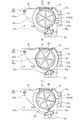
前記中枠12に配設される前記遊技盤17は、図2または図3に示すように、前面(盤面)にパチンコ球Pが流下可能な遊技領域18aが画成され、合板等の木製からなる平板状の板部材18と、該板部材18の裏面に組み付けられて前記図柄表示装置13が着脱可能に配設されると共に、後述する可動演出装置60,61や複数の発光装置等の遊技部品が配設される合成樹脂材で形成された裏ユニット19とから構成され、該裏ユニット19に形成された前後に開口する開口部19aを介して図柄表示装置13の表示部を前面側から視認し得るよう構成されている。裏ユニット19に形成される開口部19aは、該裏ユニット19の上下および左右幅の大部分が開口する大型の開口部である。ここで、前記板部材18および裏ユニット19は、外郭形状が略整合する大きさおよび形状に形成されて、該板部材18と裏ユニット19とを組み付けた状態で板部材18の裏面を裏ユニット19で全面的に覆うよう構成される。
(About game board)
As shown in FIG. 2 or FIG. 3, the game board 17 disposed in the middle frame 12 has a game area 18a in which a pachinko ball P can flow down on the front surface (board surface), and is made of wood such as plywood. The flat plate member 18 and the symbol display device 13 which are assembled to the back surface of the plate member 18 are detachably disposed, and a game such as a movable effect device 60, 61 described later and a plurality of light emitting devices. The display unit of the symbol display device 13 is opened from the front side through an opening 19a that is formed in the back unit 19 and is opened to the front and rear. It is comprised so that it can visually recognize. The opening 19a formed in the back unit 19 is a large opening in which most of the top and bottom and left and right widths of the back unit 19 are opened. Here, the plate member 18 and the back unit 19 are formed in such a size and shape that the outline shape is substantially matched, and the back surface of the plate member 18 is attached to the back unit in a state where the plate member 18 and the back unit 19 are assembled. 19 to cover the entire surface.

(板部材について)
図2に示すように、前記板部材18の前面には、円弧状に形成した案内レール20が配設されると共に、該案内レール20の右方位置に、左端縁が右方に凹む円弧状に形成した第1盤面飾り部材21が配設されている。そして、前記案内レール20および第1盤面飾り部材21により前記遊技領域18aが略円形状に画成され、該遊技領域18aに、前記中枠12に配設された図示しない打球発射装置から発射されたパチンコ球Pが遊技領域18a内に打ち出され、該遊技領域18a内をパチンコ球Pが流下して遊技が行なわれるようになっている。なお、打球発射装置から発射されたパチンコ球Pは、板部材18の下側から左側に案内レール20で案内されて、遊技領域18aの左上部に打ち出される。また、前記板部材18の遊技領域18a内には、多数の遊技釘が植設されており、該遊技領域18aを流下するパチンコ球Pは、遊技釘との接触により流下方向が不規則に変更させられるよう構成してある。なお、板部材18の盤面には、前記案内レール20の左方(遊技領域18aの外側)の上下位置に第2盤面飾り部材22が夫々が配設されている。
(About plate members)
As shown in FIG. 2, a guide rail 20 formed in an arc shape is disposed on the front surface of the plate member 18, and an arc shape in which a left end edge is recessed rightward at a right position of the guide rail 20. The 1st board surface decoration member 21 formed in this is arrange | positioned. Then, the game area 18a is defined in a substantially circular shape by the guide rail 20 and the first board surface decoration member 21, and the game area 18a is fired from a not-shown hitting ball launcher disposed on the inner frame 12. The pachinko balls P are launched into the game area 18a, and the pachinko balls P flow down in the game area 18a to play the game. The pachinko ball P launched from the ball striking device is guided by the guide rail 20 from the lower side to the left side of the plate member 18 and is launched to the upper left part of the game area 18a. In addition, a large number of game nails are planted in the game area 18a of the plate member 18, and the flow direction of the pachinko balls P flowing down the game area 18a is changed irregularly by contact with the game nails. It is configured to be able to be made. On the board surface of the plate member 18, second board surface decoration members 22 are arranged at the upper and lower positions on the left side of the guide rail 20 (outside the game area 18 a).

前記板部材18には、後述する装飾部材26の配設位置より下方位置に、前記遊技領域18aを流下するパチンコ球Pが入賞可能な始動入賞装置(入賞装置)23や特別入賞装置24が配設されている。始動入賞装置23は、前記遊技領域18aを流下するパチンコ球Pが入賞可能な上下の始動入賞口(入賞口)23aが設けられる。そして、前記始動入賞装置23の始動入賞口23aへ入賞したパチンコ球Pが始動入賞センサ(図示せず)で検出されることで、図示しない制御装置の制御信号に基づいて図柄表示装置13の表示部で図柄変動が開始されると共に、所定数(例えば5個)のパチンコ球Pが賞球として前記上下の球受け皿15,16に払い出される。なお、下側の始動入賞口23aを挟む左右位置には、相互に近接および離間するよう揺動可能な一対の羽根部材(開閉部材)23b,23bが設けられており、裏側に設けたソレノイド等の駆動手段の駆動により羽根部材23b,23bを揺動することで、下側の始動入賞口23aが開閉されるようになっている。   The plate member 18 is provided with a start winning device (winning device) 23 and a special winning device 24 that can win a pachinko ball P flowing down the game area 18a at a position below a position where a decoration member 26 described later is disposed. It is installed. The start winning device 23 is provided with upper and lower start winning ports (winning ports) 23a through which pachinko balls P flowing down the game area 18a can win. Then, the pachinko ball P won in the start winning opening 23a of the start winning device 23 is detected by a start winning sensor (not shown), so that the display on the symbol display device 13 is displayed based on a control signal of a control device (not shown). At the same time, the symbol variation is started, and a predetermined number (for example, five) of pachinko balls P are paid out to the upper and lower ball trays 15 and 16 as prize balls. A pair of blade members (opening / closing members) 23b, 23b that can be swung close to and away from each other are provided at the left and right positions sandwiching the lower start winning opening 23a, such as a solenoid provided on the back side. The lower start winning opening 23a is opened and closed by swinging the blade members 23b and 23b by driving the driving means.

前記特別入賞装置24は、入賞口24aが開閉扉(開閉部材)24bで常には閉鎖されており、前記図柄表示装置13での図柄変動の結果、図柄表示装置13に所定の図柄組み合わせ(例えば同一図柄の三つ揃い等)で図柄が停止表示されることで所謂「大当り」が発生し、これにより開閉扉24bが開放するよう作動制御されて、入賞口24aへの入賞により多数の賞球を獲得し得るようになっている。なお、板部材18には、特別入賞装置24の左右両側に、常に入賞口を開放している普通入賞装置25が夫々配設される。   In the special winning device 24, the winning opening 24a is always closed by an opening / closing door (opening / closing member) 24b, and as a result of the symbol variation in the symbol display device 13, a predetermined symbol combination (for example, the same symbol combination) When the symbol is stopped and displayed in a three-piece pattern or the like), a so-called “big hit” occurs, and the opening / closing door 24b is controlled to open, and a large number of winning balls are awarded by winning the winning opening 24a. It can be earned. The plate member 18 is provided with an ordinary winning device 25 that always opens the winning opening on the left and right sides of the special winning device 24.

(装飾部材について)
前記板部材18には、前後に貫通する貫通孔が形成されており、該貫通孔に対して前後に開口する枠状の装飾部材(所謂センター役物)26が嵌め込まれるようにして着脱自在に配設される。そして、前記裏ユニット19の開口部19aから臨む前記図柄表示装置13の表示部は、装飾部材26における前後に開口する窓口26aを介して板部材18(遊技盤17)の前側に臨んで、該図柄表示装置13の表示部で展開される図柄変動演出を前側から視認し得るようになっている。
(About decorative members)
The plate member 18 has a through-hole penetrating in the front-rear direction, and is detachable so that a frame-shaped decorative member 26 (so-called center accessory) that opens in the front-rear direction is fitted into the through-hole. Arranged. And the display part of the symbol display device 13 facing from the opening part 19a of the back unit 19 faces the front side of the plate member 18 (game board 17) through the window 26a opening front and rear in the decorative member 26, The symbol variation effect developed on the display unit of the symbol display device 13 can be viewed from the front side.

前記装飾部材26は、図4、図5に示すように、前記板部材18に開設された前記貫通孔に沿って延在する環状に形成された固定板26bと、該固定板26bに沿って設けられて、板部材18より前方へ突出する庇部26cとを備え、固定板26bの前側から板部材18にネジ止めするよう構成される。ここで、前記庇部26cは、装飾部材26(固定板26b)の左側縁の中間位置から上縁および右下縁に亘って連続して延在するよう設けられており、遊技領域18aに打ち出されたパチンコ球Pが庇部26cに沿って誘導されることで、前記図柄表示装置13の前面側を横切ってパチンコ球Pが流下(落下)するのを規制している。   As shown in FIGS. 4 and 5, the decorative member 26 includes an annular fixed plate 26 b extending along the through hole formed in the plate member 18, and the fixed plate 26 b. And a flange portion 26c that protrudes forward from the plate member 18, and is configured to be screwed to the plate member 18 from the front side of the fixed plate 26b. Here, the collar portion 26c is provided so as to continuously extend from the middle position of the left edge of the decorative member 26 (fixing plate 26b) to the upper edge and the lower right edge, and is punched into the game area 18a. The pachinko ball P thus guided is guided along the collar portion 26c, thereby restricting the pachinko ball P from flowing down (falling) across the front side of the symbol display device 13.

図6に示すように、前記装飾部材26には、窓口26aの下側に、前記固定板26bから後方へ延出すると共に左右方向にパチンコ球Pを転動可能な光透過性のステージ27が設けられている。また装飾部材26には、窓口26aの左側に、前記遊技領域18aに開口して該遊技領域18aを流下するパチンコ球Pを取込んでステージ27に案内する球通路28が設けられ、該球通路28からステージ27に通出されたパチンコ球Pは、ステージ27上を左右に転動した後に、前記各入賞装置23,24,25が配設されている遊技領域18aに排出される。なお、装飾部材26には、ステージ27の右端部に臨んで、後述する第2球転動面35aから上方に延出する右側規制壁29(図7参照)が設けられており、第2球転動面35aを転動するパチンコ球Pがステージ27の右端部から外側方に移動するのを規制している。   As shown in FIG. 6, the decorative member 26 has a light-transmitting stage 27 that extends rearward from the fixed plate 26b and can roll a pachinko ball P in the left-right direction below the window 26a. Is provided. The decorative member 26 is provided with a ball passage 28 on the left side of the window 26a. The ball passage 28 opens into the game area 18a and takes the pachinko ball P flowing down the game area 18a and guides it to the stage 27. The pachinko ball P passed from the stage 28 to the stage 27 rolls left and right on the stage 27 and is then discharged to the game area 18a in which the winning devices 23, 24, 25 are disposed. The decorative member 26 is provided with a right-side regulating wall 29 (see FIG. 7) that extends upward from a second ball rolling surface 35a, which will be described later, facing the right end of the stage 27. The pachinko ball P rolling on the rolling surface 35 a is restricted from moving outward from the right end of the stage 27.

(球通路について)
前記装飾部材26の庇部26cにおける左下端の下側に、遊技領域18aに開口する球入口30が形成された通路用装飾体31が前記固定板26bの前面に配設されており、該通路用装飾体31には球入口30に連通して窓口26a側に延在する通路が画成される。また固定板26bの裏側には、通路用装飾体31の配設位置から該固定板26bに沿って下方に延在する球導入部材32が配設され、該球導入部材32に内部画成された通路が、球導入部材32の上端部に開設された口部を介して通路用装飾体31に画成される通路に連通するよう接続される。球導入部材32の下端部には、右方(ステージ27)に向けて球出口33が開口し、該球出口33が前記ステージ27(第1の上段ステージ部34)の左端部に臨むよう構成される(図7参照、但し図7では左右逆になっている)。すなわち、実施例では通路用装飾体31に画成される通路および球導入部材32に画成される通路から前記球通路28が形成され、前記通路用装飾体31の球入口30に通入したパチンコ球Pは、球通路28を通り、球導入部材32の球出口33からステージ27に通出するよう構成されている。
(About ball passage)
A passage decoration body 31 in which a ball entrance 30 that opens to the game area 18a is formed below the lower left end of the flange portion 26c of the decoration member 26 is disposed on the front surface of the fixed plate 26b. The decorative body 31 is defined with a passage that communicates with the ball entrance 30 and extends toward the window 26a. Further, on the back side of the fixed plate 26b, a ball introducing member 32 extending downward along the fixed plate 26b from the arrangement position of the passage decoration body 31 is provided, and the ball introducing member 32 is internally defined. The passage is connected so as to communicate with the passage defined in the passage decoration body 31 through a mouth provided at the upper end of the ball introduction member 32. A sphere outlet 33 is opened at the lower end of the sphere introduction member 32 toward the right side (stage 27), and the sphere outlet 33 faces the left end of the stage 27 (first upper stage part 34). (See FIG. 7, but in FIG. 7, the left and right are reversed). That is, in the embodiment, the ball passage 28 is formed from the passage defined in the passage decoration body 31 and the passage defined in the ball introduction member 32, and enters the ball inlet 30 of the passage decoration body 31. The pachinko ball P is configured to pass through the ball passage 28 and pass out from the ball outlet 33 of the ball introduction member 32 to the stage 27.

前記通路用装飾体31にはパチンコ球Pの通過が不能な複数の透孔31aが形成され、通路用装飾体31の通路(球通路28)を通るパチンコ球Pを前側から視認可能に構成される。また前記球導入部材32は、通路(球通路28)内を視認可能な半透明な合成樹脂材で形成され、該通路(球通路28)を通るパチンコ球Pを前側から視認可能に構成されている。すなわち、遊技者にとって関心の高い前記球通路28を通るパチンコ球Pの状況を、前側から視認可能にしてある。なお、実施例では通路用装飾体31と球導入部材32とで球通路28を画成したが、球導入部材32の口部を遊技領域18aに直接開口するよう構成し、該口部を球通路28の球入口30としてもよい。   The passage decoration body 31 is formed with a plurality of through holes 31a through which the pachinko sphere P cannot pass, so that the pachinko sphere P passing through the passage (sphere passage 28) of the passage decoration body 31 is visible from the front side. The The ball introduction member 32 is formed of a translucent synthetic resin material that can visually recognize the inside of the passage (sphere passage 28), and is configured so that the pachinko sphere P passing through the passage (sphere passage 28) can be seen from the front side. Yes. That is, the situation of the pachinko ball P passing through the ball passage 28 that is of great interest to the player is made visible from the front side. In the embodiment, the ball passage 28 is defined by the decorative body 31 for the passage and the ball introduction member 32. However, the mouth portion of the ball introduction member 32 is configured to open directly to the game area 18a, and the mouth portion is formed as a ball. The ball entrance 30 of the passage 28 may be used.

前記通路用装飾体31の前端部から前記前枠14に設けたガラス板14aまでの離間寸法は、パチンコ球Pの直径よりも小さくなるよう構成されており、該通路用装飾体31の前側を通ってパチンコ球Pが窓口26a内に入り込まないようになっている。また、前記球導入部材32の前面には、通路用装飾体31の下端から後述する仕切板45の左端部までの間に亘って前方に突出する規制片32aが設けられる。この規制片32aの前端部から前記ガラス板14aまでの離間寸法もパチンコ球Pの直径よりも小さくなるよう構成されており、前記球入口30より下方でステージ27より左方の遊技領域18aを流下するパチンコ球Pが前記遊技釘等との接触により弾かれた際に、該パチンコ球Pが装飾部材26より後方に移動するのを規制片32aで規制するよう構成される。   The separation dimension from the front end of the passage decoration body 31 to the glass plate 14a provided on the front frame 14 is configured to be smaller than the diameter of the pachinko ball P, and the front side of the passage decoration body 31 is The pachinko ball P is prevented from entering the window 26a. A restricting piece 32a is provided on the front surface of the ball introduction member 32 so as to protrude forward from the lower end of the passage decoration body 31 to the left end portion of a partition plate 45 described later. The separation dimension from the front end portion of the restricting piece 32a to the glass plate 14a is also configured to be smaller than the diameter of the pachinko ball P, and flows down the game area 18a to the left of the stage 27 below the ball entrance 30. When the pachinko ball P to be played is bounced by contact with the game nail or the like, the pachinko ball P is configured to be regulated by the regulating piece 32a from moving backward from the decorative member 26.

(ステージについて)
前記ステージ27は、パチンコ球Pが転動可能な第1の上段ステージ部34および第2の上段ステージ部35を左右方向に連設した第1ステージ部材36と、該第1ステージ部材36の下側に配設されて、パチンコ球Pが転動可能な下段ステージ部37を設けた第2ステージ部材38と、両ステージ部材36,38の裏側に配設された仕切部材39とから基本的に構成される。すなわち実施例のステージ27は、パチンコ球Pが転動可能な上段ステージ部34,35と下段ステージ部37とを上下に重なるように2段で備えている。
(About the stage)
The stage 27 includes a first stage member 36 in which a first upper stage portion 34 and a second upper stage portion 35 on which a pachinko ball P can roll are connected in the left-right direction, and a lower portion of the first stage member 36. The second stage member 38 provided on the side and provided with the lower stage portion 37 on which the pachinko ball P can roll and the partition member 39 provided on the back side of the both stage members 36 and 38 are basically used. Composed. That is, the stage 27 according to the embodiment includes the upper stage portions 34 and 35 on which the pachinko balls P can roll and the lower stage portion 37 in two stages so as to overlap each other.

(第1ステージ部材について)
前記第1ステージ部材36は、図4および図5に示す如く、略一様な厚みで左右方向に延在し、パチンコ球Pが転動可能な第1の上段ステージ部34および第2の上段ステージ部35と、各上段ステージ部34,35の前端から下方に延在する上前壁部40とを備え、上前壁部40を介して装飾部材26の固定板26bにネジ止め固定されている。上前壁部40の左右方向の中間部には、図4に示す如く、左右方向に所定長さに亘って切欠部40aが形成され、該切欠部40aが、前記下段ステージ部37上のパチンコ球Pを前記遊技領域18aに排出する排出口として機能するよう構成される。また上前壁部40の裏面には、切欠部40aの左右端縁部から後方に向けて突出する一対の区画壁40b,40bが設けられ、図7および図11に示す如く、両区画壁40b,40bが下段ステージ部37における後述する第3球転動面37aの左右の端部に位置して、該第3球転動面37aを左右方向に転動するパチンコ球Pが第3球転動面37aより左右外側方に移動するのを規制するようになっている。
(About the first stage member)
As shown in FIGS. 4 and 5, the first stage member 36 extends in the left-right direction with a substantially uniform thickness, and the first upper stage portion 34 and the second upper stage on which the pachinko balls P can roll. A stage portion 35 and an upper front wall portion 40 extending downward from the front ends of the upper stage portions 34 and 35 are provided, and are screwed and fixed to the fixing plate 26b of the decorative member 26 via the upper front wall portion 40. Yes. As shown in FIG. 4, a notch portion 40 a is formed in the left-right direction at a middle portion in the left-right direction of the upper front wall portion 40, and the notch portion 40 a is a pachinko on the lower stage portion 37. The ball P is configured to function as a discharge port for discharging the ball P to the game area 18a. A pair of partition walls 40b and 40b projecting rearward from the left and right edge portions of the notch 40a are provided on the back surface of the upper front wall 40. As shown in FIGS. 7 and 11, both the partition walls 40b , 40b are positioned at the left and right ends of a later-described third ball rolling surface 37a in the lower stage portion 37, and the pachinko ball P rolling in the left and right direction on the third ball rolling surface 37a is the third ball rolling. Movement to the left and right outer sides from the moving surface 37a is restricted.

前記第1ステージ部材36は、全体が光透過性の合成樹脂材により形成されて、後述する装飾カバー62や下可動部材60aに配設した発光装置の発光によって明輝するよう構成される。なお、第1ステージ部材36におけるステージ部34,35の下面や上前壁部40の裏面には光拡散加工が施され、発光装置による発光演出効果を向上し得るよう構成される。   The first stage member 36 is entirely formed of a light-transmitting synthetic resin material, and is configured to brighten by light emission of a light emitting device disposed on a decorative cover 62 and a lower movable member 60a described later. Note that light diffusion processing is performed on the lower surfaces of the stage portions 34 and 35 and the back surface of the upper front wall portion 40 in the first stage member 36, so that the light emission effect by the light emitting device can be improved.

前記第1の上段ステージ部34および第2の上段ステージ部35は、第1ステージ部材36の左右方向の略中間位置で連設され、両ステージ部34,35を合わせた全体が、上下方向に緩やかに起伏する波形に形成されて、該ステージ部34,35上のパチンコ球Pは、上下方向に変位しながら左右に転動するようになっている。また第1ステージ部材36では、両上段ステージ部34,35が連結する中間部分が上方に突出した凸形状部分(山状の部分)となり、該凸形状部分の左側において下方に突出した凹形状部分(谷状の部分)が第1の上段ステージ部34となり、該凸形状部分の右側において下方に突出した凹形状部分(谷状の部分)が第2の上段ステージ部35となっている。すなわち、第1の上段ステージ部34の上面であってパチンコ球Pが転動可能な第1球転動面34aと、第2の上段ステージ部35の上面であってパチンコ球Pが転動可能な第2球転動面35aとは凸形成部分で連結されて、両球転動面34a,35a間をパチンコ球Pが相互に移動し得るよう構成される。実施例では、第1球転動面34aと第2球転動面35aとを連結する凸形状部分を、以後、連結凸部41と指称するものとする。   The first upper stage portion 34 and the second upper stage portion 35 are connected at a substantially intermediate position in the left-right direction of the first stage member 36, and the whole of the two stage portions 34, 35 is vertically aligned. The pachinko ball P on the stage portions 34 and 35 is formed to have a gently undulating waveform and rolls left and right while being displaced in the vertical direction. Further, in the first stage member 36, an intermediate portion where the upper stage portions 34 and 35 are connected is a convex portion (mountain portion) protruding upward, and a concave portion protruding downward on the left side of the convex portion. The (valley-shaped portion) is the first upper stage portion 34, and the concave-shaped portion (valley-shaped portion) protruding downward on the right side of the convex-shaped portion is the second upper stage portion 35. That is, the first ball rolling surface 34a on which the pachinko ball P can roll, which is the upper surface of the first upper stage portion 34, and the pachinko ball P, which is the upper surface of the second upper stage portion 35, can roll. The second ball rolling surface 35a is connected by a convex forming portion so that the pachinko balls P can move between the two ball rolling surfaces 34a and 35a. In the embodiment, the convex portion that connects the first ball rolling surface 34 a and the second ball rolling surface 35 a is hereinafter referred to as a connecting convex portion 41.

(第1の上段ステージ部について)
前記第1の上段ステージ部34の第1球転動面34aは、図7または図11に示すように、前記球通路28(球導入部材32)の球出口33に接続する左端部(図7では右端部となる)から下方に緩やかに下降するよう湾曲し、最下部から反転して緩やかに上昇(第2の上段ステージ部35に近接するにつれて上方傾斜)するよう湾曲して右端部(連結凸部41)に至るように、全体が下方に突出した凹形状(谷状)に形成される。第1球転動面34aの形状を更に詳細に述べれば、球導入部材32(球通路28)の球出口33に接続する左端部が大きな曲率で凹状に湾曲し、球通路28(球導入部材32)の球出口33を通出したパチンコ球Pを勢いよく第1球転動面34a上を転動させて右端部(連結凸部41)に到来させるよう構成される。また、第1球転動面34aの右端部が大きな曲率で凹状に湾曲し、第1球転動面34aを転動するパチンコ球Pが右端部(連結凸部41)を越えて前記第2の上段ステージ部35の第2球転動面35aに移動するのを抑制し得るようになっている。すなわち、球通路28(球導入部材32)の球出口33を通出したパチンコ球Pの勢いの違いによって、第1の上段ステージ部34から第2の上段ステージ部35に移動するパチンコ球Pと、第2の上段ステージ部35に移動することなく第1の上段ステージ部34のみを左右方向に転動するパチンコ球Pとが発生し得るよう構成される。
(About the first upper stage)
As shown in FIG. 7 or FIG. 11, the first ball rolling surface 34a of the first upper stage portion 34 is connected to the ball outlet 33 of the ball passage 28 (ball introduction member 32) (see FIG. 7). The right end portion of the right upper portion (being connected to the second upper stage portion 35). The whole is formed in a concave shape (valley shape) protruding downward so as to reach the convex portion 41). The shape of the first ball rolling surface 34a will be described in more detail. The left end connected to the ball outlet 33 of the ball introduction member 32 (ball passage 28) is curved with a large curvature into a concave shape, and the ball passage 28 (ball introduction member). The pachinko ball P that has passed through the ball outlet 33 of No. 32) is vigorously rolled on the first ball rolling surface 34a so as to arrive at the right end (the connecting convex portion 41). In addition, the right end portion of the first ball rolling surface 34a is curved in a concave shape with a large curvature, and the pachinko ball P rolling on the first ball rolling surface 34a exceeds the right end portion (connecting convex portion 41) to the second. The movement to the second ball rolling surface 35a of the upper stage portion 35 can be suppressed. That is, the pachinko sphere P moving from the first upper stage portion 34 to the second upper stage portion 35 due to the difference in momentum of the pachinko sphere P passing through the ball outlet 33 of the ball passage 28 (sphere introduction member 32) A pachinko ball P that rolls only the first upper stage part 34 in the left-right direction without moving to the second upper stage part 35 can be generated.

図4、図9または図10に示すように、全体が凹形状に形成された前記第1球転動面34aには、最下部に、前側(遊技盤17の盤面に対して直交する盤面前方)へ下方傾斜する第1球排出部(球排出部)34bが形成されている。この第1球排出部34bは、前記始動入賞装置23における始動入賞口23aの鉛直上方位置から左方に偏倚しており、前記遊技領域18aにおいて始動入賞口23aとは異なる位置に向けてパチンコ球Pを排出するよう構成される。すなわち、第1球排出部34bから遊技領域18aに排出されたパチンコ球Pの始動入賞口23aへの入賞確率は低くなっている。なお、第1ステージ部材36の前面には、第1の上段ステージ部34における左端部から第1球排出部34bの左端までの領域に亘り、第1球転動面34aより上方に突出する左装飾体42が配設される。これにより、前記球出口33から通出したパチンコ球Pが第1球排出部34bに至るまでは、該第1球転動面34aから遊技領域18aへのパチンコ球Pの排出が左装飾体42で抑制されるようになっている。   As shown in FIG. 4, FIG. 9, or FIG. 10, the first ball rolling surface 34a, which is formed in a concave shape as a whole, has a lowermost portion on the front side (front of the board orthogonal to the board surface of the game board 17). ) Is formed a first sphere discharge portion (sphere discharge portion) 34b inclined downward. The first ball discharge portion 34b is biased to the left from the vertical upper position of the starting winning port 23a in the starting winning device 23, and the pachinko ball is directed toward a position different from the starting winning port 23a in the game area 18a. It is configured to discharge P. That is, the winning probability of the pachinko ball P discharged from the first ball discharge portion 34b to the game area 18a to the start winning opening 23a is low. In addition, on the front surface of the first stage member 36, a left projecting upward from the first ball rolling surface 34a over a region from the left end portion of the first upper stage portion 34 to the left end of the first ball discharge portion 34b. A decorative body 42 is provided. Thus, until the pachinko ball P passed from the ball outlet 33 reaches the first ball discharge portion 34b, the discharge of the pachinko ball P from the first ball rolling surface 34a to the game area 18a is left decorative body 42. It is supposed to be suppressed.

(第2の上段ステージ部について)
前記第2の上段ステージ部35の第2球転動面35aは、図7または図11に示すように、前記第1の上段ステージ部34の右端部(連結凸部41)に接続する左端部(図7では右端部となる)から下方に緩やかに下降(第1の上段ステージ部34から離間するにつれて下方傾斜)するよう湾曲し、最下部から反転して緩やかに上昇するよう湾曲して右端部に至るように、全体が下方に突出した凹形状(谷状)に形成される。第2球転動面35aの形状を更に詳細に述べれば、前記第1球転動面34aの右端部(連結凸部41)に接続する左端部が大きな曲率で凹状に湾曲し、連結凸部41を越えて第2球転動面35aに至ったパチンコ球Pを勢いよく該第2球転動面35a上を転動させて右端部に到来させるよう構成される。また、第2球転動面35aの右端部が大きな曲率で凹状に湾曲し、第2球転動面35aを転動するパチンコ球Pが右端部に位置する前記右側規制壁29に勢いよく衝突するのを防止するようになっている。なお、連結凸部41を構成する前記第1球転動面34aにおける右端部の曲率より、該連結凸部41を構成する第2球転動面35aおける左端部の曲率が大きく設定され、第1球転動面34aから連結凸部41を越えて第2球転動面35aに一旦移動したパチンコ球Pが、再び第1球転動面34aに移動するのを困難にしている。
(About the second upper stage)
The second ball rolling surface 35a of the second upper stage portion 35 is, as shown in FIG. 7 or 11, a left end portion connected to the right end portion (the connecting convex portion 41) of the first upper stage portion 34. Curved so as to gently descend downward (becomes the right end in FIG. 7) (inclined downward as it is separated from the first upper stage 34), and inverted from the lowermost part and curved so as to rise gently. The whole is formed into a concave shape (valley shape) protruding downward. The shape of the second ball rolling surface 35a will be described in more detail. The left end portion connected to the right end portion (connecting convex portion 41) of the first ball rolling surface 34a is curved in a concave shape with a large curvature, and the connecting convex portion The pachinko ball P that has reached 41 and reaches the second ball rolling surface 35a is vigorously rolled on the second ball rolling surface 35a to arrive at the right end. Further, the right end portion of the second ball rolling surface 35a is concavely curved with a large curvature, and the pachinko ball P rolling on the second ball rolling surface 35a vigorously collides with the right regulation wall 29 located at the right end portion. To prevent it. The curvature of the left end portion of the second ball rolling surface 35a constituting the connection convex portion 41 is set larger than the curvature of the right end portion of the first ball rolling surface 34a constituting the connection convex portion 41, and the first It is difficult for the pachinko ball P that has once moved from the one-ball rolling surface 34a to the second ball-rolling surface 35a beyond the connecting convex portion 41 to move again to the first-ball rolling surface 34a.

図4または図10に示すように、全体が凹形状に形成された前記第2球転動面35aには、最下部に、前側(遊技盤17の盤面に対して直交する盤面前方)へ下方傾斜する第2球排出部(球排出部)35bが形成されている。この第2球排出部35bは、前記始動入賞装置23における始動入賞口23aの鉛直上方位置から右方に偏倚している。なお、第1ステージ部材36の前面には、第2の上段ステージ部35における右端部から第2球排出部35bの右端までの領域に亘り、第2球転動面35aより上方に突出する右装飾体43が配設される。これにより、第2球排出部35bより右側の第2球転動面35aから遊技領域18aへのパチンコ球Pの排出が右装飾体43で抑制されるようになっている。   As shown in FIG. 4 or FIG. 10, the second ball rolling surface 35a, which is formed in a concave shape as a whole, has a lowermost part and a front side (a front side perpendicular to the board surface of the game board 17). An inclined second sphere discharge portion (sphere discharge portion) 35b is formed. The second ball discharge portion 35b is biased to the right from the vertical upper position of the start winning opening 23a in the start winning device 23. Note that the right side of the first stage member 36 protrudes upward from the second ball rolling surface 35a across the region from the right end of the second upper stage 35 to the right end of the second ball discharge portion 35b. A decorative body 43 is provided. Thereby, discharge of the pachinko ball P from the second ball rolling surface 35a on the right side of the second ball discharge portion 35b to the game area 18a is suppressed by the right decorative body 43.

(第2ステージ部材について)
前記第2ステージ部材38は、図4および図5に示す如く、略一様な厚みで左右方向に延在し、前記第1ステージ部材36における第1および第2の上段ステージ部34,35の下方に離間して重なって位置すると共にパチンコ球Pが転動可能な下段ステージ部37と、下段ステージ部37の前端から下方に延在する下前壁部44とを備え、下前壁部44を介して装飾部材26の固定板26bにネジ止め固定されている。第2ステージ部材38を装飾部材26に配設した状態で、下段ステージ部37は、前記第1ステージ部材36の上前壁部40の切欠部40aに対応する位置で、該切欠部40aの左右幅寸法の長さで左右方向に延在している。また、第2ステージ部材38を装飾部材26に配設した状態で、第1ステージ部材36における各上段ステージ部34,35の下面と下段ステージ部37の上面(第3球転動面37a)との離間寸法は、パチンコ球Pの直径より大きく設定され、下段ステージ部37の上面(第3球転動面37a)を転動するパチンコ球Pが各上段ステージ部34,35の下面に接触しないよう構成される。なお、第2ステージ部材38における下前壁部44の前面(下段ステージ部37の前端)は、前記第1ステージ部材36における上前壁部40の前面(上段ステージ部34,35の前端)と略同一面に臨むよう構成され、前記上段ステージ部34,35の前端から遊技領域18aに直接排出されたパチンコ球Pは、下段ステージ部37に直接移動するのは極めて困難になっている。
(About the second stage member)
4 and 5, the second stage member 38 extends in the left-right direction with a substantially uniform thickness, and the first and second upper stage portions 34, 35 of the first stage member 36. The lower stage part 37 which is located below and overlaps and is capable of rolling the pachinko ball P and the lower front wall part 44 extending downward from the front end of the lower stage part 37 is provided. And is fixed to the fixing plate 26b of the decorative member 26 with screws. In a state where the second stage member 38 is disposed on the decorative member 26, the lower stage portion 37 is located at a position corresponding to the notch 40a of the upper front wall portion 40 of the first stage member 36. The width dimension extends in the left-right direction. Also, with the second stage member 38 disposed on the decorative member 26, the lower surface of each upper stage portion 34, 35 and the upper surface of the lower stage portion 37 (third ball rolling surface 37a) in the first stage member 36, Is set larger than the diameter of the pachinko ball P, and the pachinko ball P rolling on the upper surface of the lower stage portion 37 (third ball rolling surface 37a) does not contact the lower surfaces of the upper stage portions 34 and 35. It is configured as follows. The front surface of the lower front wall portion 44 in the second stage member 38 (the front end of the lower stage portion 37) is the front surface of the upper front wall portion 40 in the first stage member 36 (the front ends of the upper stage portions 34 and 35). The pachinko balls P that are configured to face substantially the same surface and are directly discharged from the front ends of the upper stage portions 34 and 35 to the game area 18a are extremely difficult to move directly to the lower stage portion 37.

前記第2ステージ部材38は、全体が光透過性の合成樹脂材により形成されて、後述する装飾カバー62や下可動部材60aに配設した発光装置の発光によって明輝するよう構成される。なお、第2ステージ部材38における下段ステージ部37の下面や下前壁部44の裏面には光拡散加工が施され、発光装置による発光演出効果を向上し得るよう構成される。   The second stage member 38 is entirely formed of a light-transmitting synthetic resin material, and is configured to brighten by light emission of a light emitting device disposed on a decorative cover 62 and a lower movable member 60a described later. Note that light diffusion processing is performed on the lower surface of the lower stage portion 37 and the back surface of the lower front wall portion 44 in the second stage member 38, so that the light emission effect by the light emitting device can be improved.

(下段ステージ部について)
前記下段ステージ部37の上面であってパチンコ球Pが転動可能な第3球転動面37aは、第1の上段ステージ部34における第1球排出部34bの左右方向の中間位置から、第2の上段ステージ部35における第2球排出部35bの左右方向の中間位置までの間に亘る対応位置において左右方向に延在している。また第3球転動面37aは、上下方向に緩やかに起伏する波形に形成されて、該第3球転動面37a上のパチンコ球Pは、上下方向に変位しながら左右に転動するようになっている。ここで、第3球転動面37aは、図6に示す如く、上方に突出した凸形状部分(山状の部分)が1箇所設けられると共に、下方に突出した凹形状部分(谷状の部分)を凸形状部分の左右両側部の2箇所に備えた起伏形状に形成されている。
(About the lower stage)
A third ball rolling surface 37a on the upper surface of the lower stage portion 37, on which the pachinko balls P can roll, is formed from the intermediate position in the left-right direction of the first ball discharge portion 34b in the first upper stage portion 34. The second upper stage portion 35 extends in the left-right direction at a corresponding position extending to the middle position in the left-right direction of the second ball discharge portion 35b. The third ball rolling surface 37a is formed in a waveform that gently undulates in the vertical direction, and the pachinko sphere P on the third ball rolling surface 37a rolls to the left and right while being displaced in the vertical direction. It has become. Here, as shown in FIG. 6, the third ball rolling surface 37 a is provided with one convex portion (mountain portion) protruding upward and a concave portion (valley portion) protruding downward. ) Is formed in an undulating shape provided at two places on both the left and right sides of the convex portion.

前記第3球転動面37aには、図4または図5に示すように、各凹形状部分の最下部に、前側(遊技盤17の盤面に対して直交する盤面前方)へ下方傾斜する第3球排出部(球排出部)37bが夫々形成されている。この第3球排出部37bは、前記始動入賞装置23における始動入賞口23aの鉛直上方位置から左方または右方に偏倚しており、前記遊技領域18aにおいて始動入賞口23aとは異なる位置に向けてパチンコ球Pを排出するよう構成される。すなわち、第3球排出部37bから遊技領域18aに排出されたパチンコ球Pの始動入賞口23aへの入賞確率は低くなっている。   As shown in FIG. 4 or FIG. 5, the third ball rolling surface 37a is inclined downwardly to the front side (front of the board perpendicular to the board surface of the game board 17) at the bottom of each concave-shaped portion. Three ball discharge portions (ball discharge portions) 37b are respectively formed. The third ball discharge portion 37b is biased leftward or rightward from the vertical upper position of the starting winning port 23a in the starting winning device 23, and is directed to a position different from the starting winning port 23a in the game area 18a. The pachinko sphere P is discharged. That is, the winning probability of the pachinko ball P discharged from the third ball discharge portion 37b to the game area 18a to the start winning opening 23a is low.

また、前記第3球転動面37aおける凸形状部分の頂部に、前側へ下方傾斜する第4球排出部(球排出部)37cが形成され、第3球転動面37aを転動するパチンコ球Pは、該第4球排出部37cから遊技領域18aへ排出可能に構成される。この第4球排出部37cは、前記始動入賞装置23における始動入賞口23aの鉛直上方位置に位置しており、該第4球排出部37cから遊技領域18aに排出されたパチンコ球Pは、始動入賞装置23の始動入賞口23aに入賞し易くなっている。すなわち、下段ステージ部37は、始動入賞装置23の始動入賞口23aに向けてパチンコ球Pを排出可能な第4球排出部37cを有することで、始動入賞装置23の始動入賞口23aに向けてパチンコ球Pを排出可能な球排出部を有していない前記第1の上段ステージ部34および第2の上段ステージ部35より、始動入賞装置23の始動入賞口23aへのパチンコ球Pの入賞確率が高くなっている。   In addition, a fourth ball discharge portion (ball discharge portion) 37c inclined downward to the front side is formed at the top of the convex portion of the third ball rolling surface 37a, and the pachinko that rolls on the third ball rolling surface 37a. The ball P is configured to be discharged from the fourth ball discharge portion 37c to the game area 18a. The fourth ball discharge portion 37c is positioned vertically above the start winning opening 23a in the start winning device 23, and the pachinko ball P discharged from the fourth ball discharge portion 37c to the game area 18a is started. It is easy to win a winning winning opening 23a of the winning device 23. That is, the lower stage portion 37 has the fourth ball discharge portion 37c that can discharge the pachinko ball P toward the start winning port 23a of the start winning device 23, so that the lower stage portion 37 faces the start winning port 23a of the start winning device 23. The winning probability of the pachinko ball P from the first upper stage portion 34 and the second upper stage portion 35 that do not have a ball discharge portion capable of discharging the pachinko ball P to the start winning port 23a of the start winning device 23 Is high.

(仕切部材について)
前記仕切部材39は、図4または図5に示す如く、左右方向の所定幅で上下方向に延在する仕切板45と、該仕切板45の上端縁において前方へ突出する庇状部46とから基本的に構成され、仕切板45が前記装飾部材26の固定板26bにネジ止めされている。仕切板45は、装飾部材26に配設した状態で、前記下段ステージ部37と上段ステージ部34,35との間の後端部を塞ぐと共に、第1の上段ステージ部34および第2の上段ステージ部35の後端を上方に向けて所定高さ延出し(図8,図9参照)、第1球転動面34a、第2球転動面35aおよび第3球転動面37a上を転動するパチンコ球Pの後方移動を規制するよう構成される。また、両上段ステージ部34,35より上方に延出する仕切板45における左端部は、前記球導入部材32に球出口33の後側で連設されると共に、該仕切板45における右端部は、前記右側規制壁29の後端部に連設するよう構成される。これにより、球通路28(球導入部材32)の球出口33から右側規制壁29までの間において、パチンコ球Pがステージ27より後方へ移動するのは規制される。なお、仕切板45における下段ステージ部37と上段ステージ部34,35との間を塞ぐ前面には、図11に示す如く、前記第3球転動面37aの起伏形状に沿って案内突条45aが左右方向に延在するよう突設されている。この案内突条45aは、第3球転動面37aを転動するパチンコ球Pが接触可能な位置に設けられると共に、該案内突条45aに接触しているパチンコ球Pは、前記第3球排出部37bや第4球排出部37cの形成部位を左右方向に通過する位置で第3球転動面37aを転動するよう構成される。すなわち、案内突条45aに接触して第3球転動面37a上を左右方向に転動しているパチンコ球Pの勢いが弱まった際には、該パチンコ球Pは第3球排出部37bおよび第4球排出部37cの何れかから遊技領域18aに排出され、パチンコ球Pが第3球転動面37a上で滞留するのを防止するべく機能する。
(About partition members)
As shown in FIG. 4 or 5, the partition member 39 includes a partition plate 45 extending in the vertical direction with a predetermined width in the left-right direction, and a hook-like portion 46 protruding forward at the upper end edge of the partition plate 45. Basically, the partition plate 45 is screwed to the fixing plate 26b of the decorative member 26. The partition plate 45 closes the rear end portion between the lower stage portion 37 and the upper stage portions 34 and 35 in a state where the partition plate 45 is disposed on the decorative member 26, and the first upper stage portion 34 and the second upper stage portion. The rear end of the stage unit 35 is extended upward by a predetermined height (see FIGS. 8 and 9), and the first ball rolling surface 34a, the second ball rolling surface 35a, and the third ball rolling surface 37a are over. It is comprised so that the backward movement of the pachinko ball P to roll may be controlled. Further, the left end portion of the partition plate 45 extending above the upper stage portions 34 and 35 is connected to the ball introduction member 32 on the rear side of the ball outlet 33, and the right end portion of the partition plate 45 is The right restriction wall 29 is configured to be connected to the rear end portion. This restricts the pachinko ball P from moving backward from the stage 27 between the ball outlet 33 of the ball passage 28 (the ball introduction member 32) and the right-side regulating wall 29. As shown in FIG. 11, a guide protrusion 45a is formed on the front surface of the partition plate 45 between the lower stage portion 37 and the upper stage portions 34, 35 along the undulating shape of the third ball rolling surface 37a. Projecting so as to extend in the left-right direction. The guide protrusion 45a is provided at a position where the pachinko ball P rolling on the third ball rolling surface 37a can come into contact, and the pachinko ball P in contact with the guide protrusion 45a is the third ball. The third ball rolling surface 37a is configured to roll at a position passing through the forming portion of the discharge portion 37b and the fourth ball discharge portion 37c in the left-right direction. That is, when the momentum of the pachinko ball P that is in contact with the guide protrusion 45a and rolls on the third ball rolling surface 37a in the left-right direction is weakened, the pachinko ball P is moved to the third ball discharge portion 37b. And it functions to prevent the pachinko ball P from being discharged to the game area 18a from any of the fourth ball discharge portions 37c and staying on the third ball rolling surface 37a.

前記庇状部46は、左端部が前記球通路28(球導入部材32)の球出口33の上方位置において前記規制片32aの右端部に連設すると共に、右端部が前記右側規制壁29の上端部に連設するよう構成されている。そして、図8に示す庇状部46の前端部から前記前枠14に設けたガラス板14aまでの離間寸法Lは、パチンコ球Pの直径よりも小さく設定されており、該庇状部46の前端部側から庇状部46の上方へパチンコ球Pが移動しないよう構成される。すなわち、前記遊技領域18aを流下するパチンコ球Pが、前記遊技釘等との接触により弾かれてステージ27側に移動した際に、該パチンコ球Pがステージ27より後方へ移動するのを仕切板45および庇状部46で規制するようになっている。   The flange 46 has a left end connected to the right end of the restricting piece 32 a at a position above the ball outlet 33 of the ball passage 28 (sphere introducing member 32), and a right end of the right restricting wall 29. It is comprised so that it may connect with an upper end part. 8 is set to be smaller than the diameter of the pachinko ball P, and the distance L from the front end of the bowl-shaped portion 46 shown in FIG. 8 to the glass plate 14a provided on the front frame 14 is set. The pachinko ball P is configured not to move from the front end side to the upper side of the bowl-shaped portion 46. That is, when the pachinko ball P flowing down the game area 18a is bounced by contact with the game nail or the like and moves to the stage 27 side, the pachinko ball P moves backward from the stage 27. It regulates by 45 and the bowl-shaped part 46. FIG.

前記仕切部材39は、透明な合成樹脂材により形成され、前記仕切板45を透して後側に配設される後述の下可動部材60aを視認可能に構成される。なお、仕切板45における上段ステージ部34,35より下方に臨む裏面に光拡散加工が施され、後述する発光装置による発光演出効果を向上し得るよう構成される。   The partition member 39 is formed of a transparent synthetic resin material, and is configured to be visible through a lower movable member 60a described later disposed on the rear side through the partition plate 45. In addition, it is comprised so that the light-diffusion process may be given to the back surface which faces the lower stage parts 34 and 35 in the partition plate 45, and the light emission effect effect by the light-emitting device mentioned later can be improved.

(連絡通路について)
前記第1ステージ部材36には、図10に示す如く、前記第2の上段ステージ部35における第2球排出部35bの前側において、左側(連結凸部41側)に偏った位置で前方に向けて膨出する通路画成部63が設けられ、該通路画成部63に球入口47aが上方に向けて開設されている。この通路画成部63には、前記右側の区画壁40bより左側において前記第3球転動面37aの右端部前側で開口する球出口47bが設けられている。そして、第2球排出部35bから球入口47aに通入したパチンコ球Pは、通路画成部63内に画成される連絡通路47を通って球出口47bから第3球転動面37a上に通出するよう構成される。
(About communication passage)
As shown in FIG. 10, the first stage member 36 is directed forward at a position biased to the left side (the connecting convex portion 41 side) on the front side of the second ball discharge portion 35 b in the second upper stage portion 35. A passage defining portion 63 that bulges out is provided, and a ball inlet 47 a is opened upward in the passage defining portion 63. The passage defining portion 63 is provided with a ball outlet 47b that opens on the right side of the third ball rolling surface 37a on the left side of the right partition wall 40b. Then, the pachinko sphere P that has entered the sphere inlet 47a from the second sphere discharge portion 35b passes through the communication passage 47 defined in the passage definition portion 63, and then on the third sphere rolling surface 37a from the sphere outlet 47b. Configured to go out.

前記下段ステージ部37にパチンコ球Pを通出可能な連絡通路47の球入口47aを、前記第2の上段ステージ部35上に開口するよう構成したので、該第2の上段ステージ部35上のパチンコ球Pが下段ステージ部37に移動する確率は、下段ステージ部37にパチンコ球Pを通出可能な専用の通路を設けていない前記第1の上段ステージ部34上のパチンコ球Pが下段ステージ部37へ移動する確率より高くなっている。   Since the ball inlet 47a of the communication passage 47 through which the pachinko ball P can pass to the lower stage portion 37 is configured to open on the second upper stage portion 35, the second upper stage portion 35 The probability that the pachinko ball P moves to the lower stage portion 37 is that the pachinko ball P on the first upper stage portion 34 is not provided with a dedicated passage through the lower stage portion 37 through which the pachinko ball P can pass. The probability of moving to the part 37 is higher.

(球誘導通路について)
前記第1ステージ部材36には、図10に示す如く、前記第2の上段ステージ部35における第2球排出部35aの前側において、右側(連結凸部41から離間する側)に偏った位置で前記連絡通路47の球入口47aと並んで球入口52aを上方に向けて開口する第1球誘導通路画成部48が設けられている。この第1球誘導通路画成部48は、前記右側の区画壁40bより右側において後方に向けて出口が開口している。また前記仕切部材39には、第1球誘導通路画成部48の出口に対応する位置で前方に向けて入口を開口した第2球誘導通路画成部49が設けられ、第1球誘導通路画成部48の出口と第2球誘導通路画成部49の入口とが連通している。すなわち、第2球排出部35aから球入口52aに通入したパチンコ球Pは、第1球誘導通路画成部48内に画成される通路を通って第2球誘導通路画成部49内に画成される通路に通入するよう構成される。
(About the ball guide passage)
As shown in FIG. 10, the first stage member 36 is biased to the right side (side away from the connecting convex portion 41) on the front side of the second ball discharge portion 35 a in the second upper stage portion 35. A first sphere guide passage defining portion 48 is provided along with the sphere inlet 47a of the communication passage 47 so as to open the sphere inlet 52a upward. The first sphere guide passage defining portion 48 has an outlet that opens rearward on the right side of the right partition wall 40b. Further, the partition member 39 is provided with a second sphere guide passage defining portion 49 having an inlet opening forward at a position corresponding to the outlet of the first sphere guide passage defining portion 48, and the first sphere guide passage is provided. The outlet of the defining unit 48 and the inlet of the second ball guiding passage defining unit 49 communicate with each other. That is, the pachinko sphere P that has entered the sphere inlet 52a from the second sphere discharge portion 35a passes through the passage defined in the first sphere guide passage definition portion 48, and enters the second sphere guide passage definition portion 49. Configured to enter a passage defined by

前記第2球誘導通路画成部49は、図4または図5に示す如く、前記仕切板45の前側に突出して前記入口を画成する略U字状の前通路壁49aと、該仕切板45の後側に突出して後方に開放する後通路壁49bと、該後通路壁49bの後部開口を閉塞する蓋部材50とから構成される。第2球誘導通路画成部49における後通路壁49bと蓋部材50とで構成される部分は、ステージ27の左右方向の略中央位置に向けて下方傾斜し、該傾斜下端で下方に向けて出口が開口している。また、前記装飾部材26の下縁部における左右方向に中央位置には、図4または図8に示す如く、前端から後方に向けて所定長さで延在する樋部51が設けられ、該樋部51の後端部に前記第2球誘導通路画成部49の出口が連通するよう接続される。この樋部51は、前方に向けて下方傾斜すると共に、該樋部51の前部は、前記第2ステージ部材38の下前壁部44に開設した球出口52bに連通接続されている。すなわち、前記第1球誘導通路画成部48内に画成される通路から第2球誘導通路画成部49内に画成される通路に通入したパチンコ球Pは、樋部51を流下して球出口52bから前記遊技領域18aに排出されるようになっている。第2ステージ部材38の下前壁部44に開設した球出口52bは、前記始動入賞装置23における始動入賞口23aの鉛直上方位置に位置し、該球出口52bから遊技領域18aに排出されたパチンコ球Pは、始動入賞口23aに高確率で入賞するよう構成される。実施例では、第1球誘導通路画成部48、第2球誘導通路画成部49および樋部51から、球誘導通路52が構成され、第1球誘導通路画成部48の球入口52aが、球誘導通路52の球入口として機能し、下前壁部44の球出口52bが、球誘導通路52の球出口として機能する。   As shown in FIG. 4 or FIG. 5, the second sphere guide passage defining portion 49 projects from the front side of the partition plate 45 to form a substantially U-shaped front passage wall 49a that defines the inlet, and the partition plate. The rear passage wall 49b protrudes rearward and opens rearward, and the lid member 50 closes the rear opening of the rear passage wall 49b. The portion constituted by the rear passage wall 49b and the lid member 50 in the second sphere guide passage defining portion 49 is inclined downward toward the substantially central position in the left-right direction of the stage 27, and directed downward at the lower end of the inclination. The outlet is open. Further, as shown in FIG. 4 or FIG. 8, a flange 51 extending at a predetermined length from the front end to the rear is provided at the central position in the left-right direction at the lower edge of the decorative member 26. The outlet of the second spherical guide passage defining portion 49 is connected to the rear end portion of the portion 51 so as to communicate therewith. The flange 51 is inclined downward toward the front, and the front portion of the flange 51 is connected to a ball outlet 52b formed in the lower front wall 44 of the second stage member 38. That is, the pachinko ball P that has entered the passage defined in the second sphere guide passage defining portion 49 from the passage defined in the first sphere guide passage defining portion 48 flows down the collar portion 51. Then, it is discharged from the ball outlet 52b to the game area 18a. The ball outlet 52b opened in the lower front wall portion 44 of the second stage member 38 is positioned vertically above the start winning opening 23a in the start winning device 23, and is discharged from the ball outlet 52b into the game area 18a. The ball P is configured to win the start winning opening 23a with high probability. In the embodiment, a sphere guide passage 52 is constituted by the first sphere guide passage defining portion 48, the second sphere guide passage defining portion 49, and the flange portion 51, and the sphere inlet 52 a of the first sphere guide passage defining portion 48 is formed. However, the ball outlet 52 b of the lower front wall 44 functions as the ball outlet of the ball guide passage 52.

前記前通路壁49aの内底面には、左右幅方向の中央に後方に向けて下方傾斜する案内条49cが突設され、球誘導通路52を第1球誘導通路画成部48側から第2球誘導通路画成部49側へ移動したパチンコ球Pを、該案内条49cによって後方に向けて案内するよう構成される。また、前記蓋部材50の前面には、前記後通路壁49bの右端部(傾斜上端側)に臨む位置に三角形状に形成された偏向突起50aが、前側を向く傾斜面を右側から左側に向けて傾斜する姿勢で設けられる。すなわち、球誘導通路52を前通路壁49a側から後通路壁49b側へ向けて後方に移動するパチンコ球Pの進路を、偏向突起50aの傾斜面で左方に向けて円滑に偏向するよう構成される。なお、蓋部材50の前面には、球誘導通路52内に臨む位置に、上下方向に離間して一対の突条50b,50bが後通路壁49bで画成される球誘導通路52の傾斜に沿って左右方向に延在している。この突条50b,50bは、後通路壁49bに蓋部材50を取付ける際に後通路壁49bの上下内面に当接して、当該蓋部材50を位置決めするべく機能する。   On the inner bottom surface of the front passage wall 49a, a guide strip 49c that inclines downward toward the rear in the center in the left-right width direction protrudes, and the sphere guide passage 52 is second from the first sphere guide passage defining portion 48 side. The pachinko ball P that has moved to the side of the ball guide passage defining portion 49 is configured to be guided rearward by the guide strip 49c. Further, a deflecting projection 50a formed in a triangular shape at a position facing the right end (inclined upper end side) of the rear passage wall 49b on the front surface of the lid member 50 has an inclined surface facing the front side directed from the right side to the left side. Provided in an inclined posture. That is, the path of the pachinko sphere P that moves rearward from the front passage wall 49a side to the rear passage wall 49b side of the ball guide passage 52 is smoothly deflected to the left by the inclined surface of the deflection protrusion 50a. Is done. In addition, on the front surface of the lid member 50, the pair of protrusions 50 b and 50 b are spaced apart in the vertical direction at a position facing the inside of the ball guide passage 52, and the ball guide passage 52 is inclined by the rear passage wall 49 b. Along the left-right direction. The protrusions 50b and 50b function to position the lid member 50 by contacting the upper and lower inner surfaces of the rear passage wall 49b when the lid member 50 is attached to the rear passage wall 49b.

前記樋部51には、前記第2球誘導通路画成部49における出口との連通部に対応する位置に、左右方向に離間する一対の傾斜突起51a,51aが突設されている。各傾斜突起51aの上側を向く傾斜面は、後側から前側に向けて下方傾斜するよう形成され、球誘導通路52において第2球誘導通路画成部49の出口から通出したパチンコ球Pの進路を、傾斜突起51a,51aの傾斜面によって前側へ向けて円滑に偏向するよう構成される。なお、樋部51や前記蓋部材50は、何れも光透過性の合成樹脂材により形成されて、後述する装飾カバー62や下可動部材60aに配設した発光装置の発光によって明輝するよう構成される。また蓋部材50の裏面には光拡散加工が施され、発光装置による発光演出効果を向上し得るようになっている。   A pair of inclined protrusions 51 a and 51 a that are separated in the left-right direction protrude from the flange 51 at a position corresponding to the communication portion with the outlet in the second sphere guide passage defining portion 49. The inclined surface facing the upper side of each inclined protrusion 51a is formed so as to be inclined downward from the rear side toward the front side, and the pachinko sphere P passing through the exit of the second sphere guide passage defining portion 49 in the sphere guide passage 52 is formed. The path is configured to be smoothly deflected toward the front side by the inclined surfaces of the inclined protrusions 51a and 51a. Note that the flange 51 and the lid member 50 are both formed of a light-transmitting synthetic resin material, and are configured to brighten by light emission of a light emitting device disposed on a decorative cover 62 and a lower movable member 60a described later. The Further, the back surface of the lid member 50 is subjected to light diffusion processing so that the light emission effect by the light emitting device can be improved.

なお、前記通路画成部63および第1球誘導通路画成部48の各前端部は、前記庇状部46における前端部の位置と略同一位置に臨むよう構成され(図8参照)、該通路画成部63または第1球誘導通路画成部48と前記ガラス板14aとの間にパチンコ球Pが嵌り込まないようになっている。   The front end portions of the passage defining portion 63 and the first ball guiding passage defining portion 48 are configured to face substantially the same position as the front end portion of the bowl-shaped portion 46 (see FIG. 8), The pachinko sphere P is not fitted between the passage defining portion 63 or the first sphere guiding passage defining portion 48 and the glass plate 14a.

(規制部について)
前記第1ステージ部材36には、前記第1の上段ステージ部34と第2の上段ステージ部35との連結部位である連結凸部41の下面に、上方に向けて凹む凹部53が形成されている。また第1ステージ部材36の上前壁部40における連結凸部41に対応する位置に、装飾部品54が配設される。この装飾部品54は、図4または図5に示す如く、当該パチンコ機10のモチーフに合わせた形状に形成された装飾部54aと、該装飾部54aの裏面から突出する固定用ボス54bとから基本的に構成される。装飾部54aの裏面には、固定用ボス54bを挟む左右両側に位置決めピン54cが夫々突設され、該位置決めピン54cを、前記上前壁部40に設けた対応する位置決め孔40cに前側から嵌挿することで、上前壁部40に対して装飾部品54が位置決めされる。また、前記仕切部材39における仕切板45には、凹部53に対応する位置にネジ通孔45bが形成され、該ネジ通孔45bに後方から挿通したネジを固定用ボス54bに設けたネジ孔に螺挿することで、装飾部品54を定位置で固定するよう構成される。
(Regulatory Department)
The first stage member 36 is formed with a concave portion 53 that is recessed upward on the lower surface of a connecting convex portion 41 that is a connecting portion between the first upper stage portion 34 and the second upper stage portion 35. Yes. In addition, a decorative component 54 is disposed at a position corresponding to the connecting convex portion 41 in the upper front wall portion 40 of the first stage member 36. As shown in FIG. 4 or FIG. 5, the decorative part 54 is basically composed of a decorative part 54a formed in a shape matching the motif of the pachinko machine 10 and a fixing boss 54b protruding from the back surface of the decorative part 54a. Constructed. On the back surface of the decorative portion 54a, positioning pins 54c project from the left and right sides of the fixing boss 54b, and the positioning pins 54c are fitted into the corresponding positioning holes 40c provided in the upper front wall portion 40 from the front side. By inserting, the decorative component 54 is positioned with respect to the upper front wall portion 40. Further, the partition plate 45 in the partition member 39 is formed with a screw through hole 45b at a position corresponding to the recess 53, and a screw inserted through the screw through hole 45b from the rear is formed into a screw hole provided in the fixing boss 54b. By screwing, the decorative part 54 is configured to be fixed at a fixed position.

前記装飾部品54を位置決めピン54c,54cおよび固定用ボス54bで定位置に位置決め固定した状態で、該固定用ボス54bは、図11または図12に示す如く、前記凹部53おける下開口の左右方向の略中央位置において該凹部53の前後方向に全長に亘って延在するよう設定される。そして、固定用ボス54bと凹部53における左右の開口縁部との隙間寸法は、パチンコ球Pの直径より小さくなるよう構成される。すなわち、前記連絡通路47から第3球転動面37a上に移動したパチンコ球P、または遊技領域18aから直接第3球転動面37a上に移動したパチンコ球Pが、凹部53に嵌り込んでしまうのを固定用ボス54bで防止し得るようになっている。すなわち、実施例では、固定用ボス54bが規制部として機能する。   In a state where the decorative part 54 is positioned and fixed at a fixed position by positioning pins 54c and 54c and a fixing boss 54b, the fixing boss 54b is arranged in the horizontal direction of the lower opening in the recess 53 as shown in FIG. Is set so as to extend over the entire length in the front-rear direction of the recess 53. The gap dimension between the fixing boss 54 b and the left and right opening edges of the recess 53 is configured to be smaller than the diameter of the pachinko ball P. That is, the pachinko ball P that has moved from the communication passage 47 onto the third ball rolling surface 37 a or the pachinko ball P that has moved directly from the game area 18 a onto the third ball rolling surface 37 a is fitted into the recess 53. This can be prevented by the fixing boss 54b. That is, in the embodiment, the fixing boss 54b functions as a restricting portion.

前記固定用ボス54bにおける下段ステージ部37の第3球転動面37aに対向する下面には、後側から前側に向けて下方傾斜する傾斜面54dが形成されている。すなわち、前記連絡通路47から第3球転動面37a上に移動したパチンコ球P、または遊技領域18aから直接第3球転動面37a上に移動したパチンコ球Pが跳ねて固定用ボス54bの傾斜面54dに接触した際には、該パチンコ球Pを確実に下方に向けて跳ね返すことができ、前記凹部53にパチンコ球Pが嵌り込むのを確実に防止し得る。   On the lower surface of the fixing boss 54b facing the third ball rolling surface 37a of the lower stage portion 37, an inclined surface 54d that is inclined downward from the rear side toward the front side is formed. That is, the pachinko ball P that has moved from the communication passage 47 onto the third ball rolling surface 37a, or the pachinko ball P that has moved directly from the game area 18a onto the third ball rolling surface 37a, jumps to the fixing boss 54b. When contacting the inclined surface 54d, the pachinko ball P can be reliably rebounded downward, and the pachinko ball P can be reliably prevented from fitting into the recess 53.

なお、前記第1の上段ステージ部34および第2の上段ステージ部35の下面には、図12に示す如く、凹部53の左右の開口縁の夫々に対応して、下方に突出する規制突条55が該凹部53の前後方向の全長に亘って設けられる。そして、固定用ボス54bと凹部53の左右の開口縁部との隙間寸法を規制突条55,55でより小さくして、凹部53へのパチンコ球Pの嵌り込みを確実に防止するよう構成される。すなわち、実施例では、規制突条55も規制部として機能するようになっている。   In addition, on the lower surfaces of the first upper stage portion 34 and the second upper stage portion 35, as shown in FIG. 12, a regulating protrusion protruding downward corresponding to the left and right opening edges of the recess 53, respectively. 55 is provided over the entire length of the recess 53 in the front-rear direction. Further, the gap between the fixing boss 54b and the left and right opening edges of the recess 53 is made smaller by the restricting protrusions 55, 55, and the pachinko ball P is surely prevented from being fitted into the recess 53. The That is, in the embodiment, the regulation protrusion 55 also functions as a regulation unit.

(裏ユニットについて)
前記裏ユニット19は、図3に示すように、前方に開口する矩形箱状に形成された箱状本体56と、該箱状本体56の開口前端部に形成されて当該箱状本体56の開口外側へ延出し、前記板部材18の裏面に当接する取付部57とから構成される。箱状本体56は、前記板部材18に対向する矩形板状に形成された対向面部58と、該対向面部58における上下左右の各縁部から前方に延出する画壁部(壁部)59とから前方に開口するよう形成されて、各画壁部59の前端部から箱状本体56の開口外側へ向けて延出するよう前記取付部57が形成されている。そして、取付部57の前面を板部材18の裏面に当接した状態で、ネジを介して板部材18に裏ユニット19が着脱自在に固定される。
(About the back unit)
As shown in FIG. 3, the back unit 19 has a box-shaped main body 56 formed in a rectangular box shape that opens to the front, and an opening front end portion of the box-shaped main body 56. The mounting portion 57 extends outward and contacts the back surface of the plate member 18. The box-shaped main body 56 includes a facing surface portion 58 formed in a rectangular plate shape facing the plate member 18, and an image wall portion (wall portion) 59 extending forward from each of the upper, lower, left and right edges of the facing surface portion 58. The attachment portion 57 is formed so as to open forward from the front end of each of the wall portions 59 and extend outward from the opening of the box-shaped main body 56. Then, the back unit 19 is detachably fixed to the plate member 18 via screws in a state where the front surface of the mounting portion 57 is in contact with the back surface of the plate member 18.

前記対向面部58に、上下および左右幅の大部分が開口する大型の前記開口部19aが形成されており、以下の説明において、対向面部58における開口部19aに対する上下左右に位置する部分について、上対向面部58a、下対向面部58b、左対向面部58c、右対向面部58dと夫々指称するものとする。   The opposing surface portion 58 is formed with the large opening portion 19a that opens most of the vertical and horizontal widths. In the following description, the upper surface portion of the opposing surface portion 58 that is located above and below the opening portion 19a The facing surface portion 58a, the lower facing surface portion 58b, the left facing surface portion 58c, and the right facing surface portion 58d are respectively referred to.

前記板部材18の裏側に裏ユニット19を取付けた状態で、該裏ユニット19の対向面部58と板部材18との間に所要の空間が画成され、裏ユニット19の対向面部58に設けられる前記可動演出装置60,61や各種の発光装置が該空間に臨むよう構成される。前記下対向面部58bの前面には、裏側に発光装置を備える光透過性の装飾カバー62が配設されている。装飾カバー62は、前記仕切部材39における仕切板45の後側に臨んでおり、発光装置のLEDを発光することで、装飾カバー62および仕切板45を介して前記ステージ27を裏側から照らして発光演出を行ない得るよう構成される。なお、装飾カバー62には光拡散加工が施され、LEDによる発光演出効果を向上すると共に、発光装置の前側からの視認性を困難にして、見栄えの低下を防止するようになっている。   In a state where the back unit 19 is attached to the back side of the plate member 18, a required space is defined between the facing surface portion 58 of the back unit 19 and the plate member 18, and is provided on the facing surface portion 58 of the back unit 19. The movable effect devices 60 and 61 and various light emitting devices are configured to face the space. On the front surface of the lower facing surface portion 58b, a light transmissive decorative cover 62 having a light emitting device on the back side is disposed. The decorative cover 62 faces the rear side of the partition plate 45 in the partition member 39, and emits light by illuminating the stage 27 from the back side through the decorative cover 62 and the partition plate 45 by emitting the LED of the light emitting device. It is configured to be able to produce an effect. The decorative cover 62 is subjected to a light diffusing process so as to improve the light emission effect by the LED, make the visibility from the front side of the light emitting device difficult, and prevent the appearance from being deteriorated.

(下可動演出装置について)
前記装飾カバー62の前側に下可動演出装置60が配設される。該下可動演出装置60は、図3に示す如く、装飾カバー62における右端部に回動支点を有する下可動部材60aを備え、該下可動部材60aを駆動機構(図示せず)によって第1位置と第2位置との間を揺動するよう構成されている。下可動部材60aは、裏ユニット19における開口部19aの横幅寸法より長い長尺で大型の部材であって、実施例ではパチンコ機のモチーフに応じた刀を模した形状に形成されている。
(About the lower movable effect device)
A lower movable effect device 60 is disposed on the front side of the decorative cover 62. As shown in FIG. 3, the lower movable effect device 60 includes a lower movable member 60a having a rotation fulcrum at the right end of the decorative cover 62, and the lower movable member 60a is moved to a first position by a drive mechanism (not shown). And a second position. The lower movable member 60a is a long and large member that is longer than the lateral width dimension of the opening 19a in the back unit 19, and in the embodiment, is formed in a shape imitating a sword according to a motif of a pachinko machine.

前記下可動部材60aは、通常時には裏ユニット19の開口下端縁に沿って左右方向に水平に延在する姿勢となる第1位置(図3の実線参照)に保持され、第1位置において下可動部材60aの前側には、前記上段ステージ部34,35から上方に延出する仕切板45が位置するよう構成されて、該仕切板45を介して下可動部材60aの一部が前側から視認可能に構成される。そして、下可動部材60aが第1位置から第2位置(図3の二点鎖線参照)に移動することで、前記装飾部材26の窓口26a内において図柄表示装置13における表示部の前側略中央を斜めに横切るように該下可動部材60aが臨むよう構成される。実施例では、下可動部材60aの内部に発光装置が配設されると共に、該下可動部材60aの前面には複数の光透過部が形成され、発光装置のLEDの光が光透過部を介して前側に照射可能に構成されている。すなわち、下可動部材60aの第1位置において、該下可動部材60aに内蔵の発光装置により行なわれる発光演出は、前記仕切板45を介して前側から視認し得るようになっている。   The lower movable member 60a is normally held at a first position (see the solid line in FIG. 3) that extends horizontally in the left-right direction along the lower edge of the opening of the back unit 19, and is movable downward at the first position. A partition plate 45 extending upward from the upper stage portions 34 and 35 is positioned on the front side of the member 60a, and a part of the lower movable member 60a is visible from the front side through the partition plate 45. Configured. Then, the lower movable member 60a moves from the first position to the second position (see the two-dot chain line in FIG. 3), so that the front center of the display unit in the symbol display device 13 is located in the window 26a of the decorative member 26. The lower movable member 60a is configured to face diagonally. In the embodiment, the light emitting device is disposed inside the lower movable member 60a, and a plurality of light transmitting portions are formed on the front surface of the lower movable member 60a, and the light of the LED of the light emitting device passes through the light transmitting portion. The front side can be irradiated. That is, at the first position of the lower movable member 60a, the light emission effect performed by the light emitting device built in the lower movable member 60a can be viewed from the front side through the partition plate 45.

前記裏ユニット19の上対向面部58a、左対向面部58cおよび右対向面部58dには、図示しないが複数の発光装置が配設され、各発光装置のLEDを発光することにより、前記図柄表示装置13における表示部の周囲を光により演出して遊技の興趣を向上し得るよう構成される。   Although not shown, a plurality of light emitting devices are arranged on the upper facing surface portion 58a, the left facing surface portion 58c, and the right facing surface portion 58d of the back unit 19, and the symbol display device 13 emits light from the LED of each light emitting device. It is configured to enhance the entertainment of the game by directing the surroundings of the display unit with light.

(上可動演出装置について)
図13〜図16に示すように、前記上可動演出装置61は、前記裏ユニット19に配設される装置本体65と、該装置本体65に配設された駆動モータ(駆動手段)79と、当該装置本体65に所定範囲で往復移動し得るよう支持された上可動部材80と、該駆動モータ79および上可動部材80を接続して駆動モータ79の駆動力を上可動部材80に伝達する駆動伝達手段95とを備えている。そして、前記制御装置に対して前記駆動モータ79が配線接続されており、該制御装置からの制御信号に基づいて駆動モータ79を駆動することで、前記駆動伝達手段95を介して前記上可動部材80が往復移動するよう構成される。ここで、実施例の上可動部材80は、後述するように初期位置(第1の折返し位置)および可動位置(第2の折返し位置)の間を往復回転するよう構成される。なお、実施例では、前記駆動モータ79としてステッピングモータが採用されている。
(Upper movable production device)
As shown in FIGS. 13 to 16, the upper movable effect device 61 includes a device main body 65 disposed in the back unit 19, a drive motor (drive means) 79 disposed in the device main body 65, and The upper movable member 80 supported so as to be able to reciprocate within a predetermined range with the apparatus main body 65, and the drive motor 79 and the upper movable member 80 are connected to transmit the driving force of the drive motor 79 to the upper movable member 80. And a transmission means 95. The drive motor 79 is wired to the control device, and the upper movable member is driven via the drive transmission means 95 by driving the drive motor 79 based on a control signal from the control device. 80 is configured to reciprocate. Here, the upper movable member 80 of the embodiment is configured to reciprocate between an initial position (first folding position) and a movable position (second folding position) as described later. In the embodiment, a stepping motor is employed as the drive motor 79.

(装置本体について)
前記装置本体65は、図15、図16に示すように、前記裏ユニット19の対向面部58(上対向面部58a)に固定される後側ケース部材66と、該後側ケース部材66の前側に配設される前側ケース部材69とから構成されて、該前後のケース部材66,69をネジ止めすることで、前記駆動伝達手段95を収容する空間部65aが内部画成される。すなわち、前記後側ケース部材66は、前記裏ユニット19の対向面部58に対向する平板状の後板部67と、該後板部67の外周縁から前方へ延出する後側外周壁部68とを備えると共に、前記前側ケース部材69は、該後側ケース部材66の後板部67に対向する前板部70と、該前板部70の外周縁から後方へ延出する前側外周壁部71とを備えて、当該前板部70の適宜位置に形成されたネジ通孔70aに挿通したネジを後板部67に形成されたネジ孔67aに螺挿することで、両ケース部材66,69が前記空間部65aを内部画成するよう組み付けられる。
(About the main unit)
As shown in FIGS. 15 and 16, the apparatus main body 65 includes a rear case member 66 fixed to the facing surface portion 58 (upper facing surface portion 58 a) of the back unit 19, and a front side of the rear case member 66. A space portion 65a for accommodating the drive transmission means 95 is internally defined by screwing the front and rear case members 66, 69. That is, the rear case member 66 includes a flat plate-like rear plate portion 67 that faces the opposed surface portion 58 of the back unit 19, and a rear outer peripheral wall portion 68 that extends forward from the outer peripheral edge of the rear plate portion 67. The front case member 69 includes a front plate portion 70 facing the rear plate portion 67 of the rear case member 66, and a front outer peripheral wall portion extending rearward from the outer peripheral edge of the front plate portion 70. 71, and by inserting a screw inserted through a screw hole 70a formed at an appropriate position of the front plate portion 70 into a screw hole 67a formed in the rear plate portion 67, both case members 66, 69 is assembled so as to internally define the space 65a.

ここで、前記後側外周壁部68および前側外周壁部71は、前記前後のケース部材66,69を組み付けた際に相互に干渉しない位置に形成されており、両ケース部材66,69を組み付けた際に装置本体65の外周面を構成するようになっている(図14参照)。なお、実施例の上可動演出装置61では、前記後側ケース部材66の後側外周壁部68が装置本体65の上面および右側面を形成すると共に、前記前側ケース部材69の前側外周壁部71が装置本体65の下面および左側面を形成している。また、前記装置本体65の右側面(すなわち後側外周壁部68において装置本体65の右側面を画成する部位)に、前記空間部65aを装置外部に連通する操作窓73が形成されている。前記操作窓73には、前記駆動伝達手段95を構成する駆動歯車96の一部分が臨むよう構成されており、該操作窓73を介して装置本体65の外部から駆動歯車96を直接回転操作し得るようになっている。   Here, the rear outer peripheral wall portion 68 and the front outer peripheral wall portion 71 are formed at positions where they do not interfere with each other when the front and rear case members 66 and 69 are assembled, and the case members 66 and 69 are assembled. In this case, the outer peripheral surface of the apparatus main body 65 is configured (see FIG. 14). In the upper movable effect device 61 of the embodiment, the rear outer peripheral wall portion 68 of the rear case member 66 forms the upper surface and the right side surface of the device main body 65 and the front outer peripheral wall portion 71 of the front case member 69. Forms the lower surface and the left side surface of the apparatus main body 65. In addition, an operation window 73 is formed on the right side surface of the apparatus main body 65 (that is, the portion defining the right side surface of the apparatus main body 65 in the rear outer peripheral wall portion 68) to communicate the space 65a with the outside of the apparatus. . The operation window 73 is configured such that a part of the drive gear 96 constituting the drive transmission means 95 faces, and the drive gear 96 can be directly rotated from the outside of the apparatus main body 65 through the operation window 73. It is like that.

図15に示すように、前記前側ケース部材69の前板部70には、前面右側部に前後に駆動軸挿通孔72aが形成されたモータ設置部72が形成されている。そして、前記駆動軸挿通孔72aに駆動軸79aを前方から挿通した姿勢で前記駆動モータ79が前記モータ設置部72に取付けられると共に、該駆動軸79aに対して前記空間部65a内で駆動歯車96が固定されている。更に、前記前側ケース部材69の前板部70には、左右方向に離間する位置に、前後方向に軸孔74a,75aが貫通する筒状部74,75が前方へ突出するよう形成されており、モータ設置部72に近接する右側位置の第1筒状部74の軸孔74aに、前記駆動伝達手段95を構成する従動歯車97に連結した支軸98が回転可能に挿通されると共に、左側位置の第2筒状部75の軸孔75aに、前記上可動部材80に連結された回転軸81が回転可能に挿通されている。   As shown in FIG. 15, the front plate portion 70 of the front case member 69 is formed with a motor installation portion 72 in which a drive shaft insertion hole 72a is formed in the front and rear on the right side of the front surface. The drive motor 79 is attached to the motor installation portion 72 in a posture in which the drive shaft 79a is inserted from the front into the drive shaft insertion hole 72a, and the drive gear 96 is disposed in the space 65a with respect to the drive shaft 79a. Is fixed. Further, the front plate portion 70 of the front case member 69 is formed with cylindrical portions 74, 75 through which the shaft holes 74a, 75a penetrate in the front-rear direction at positions spaced apart in the left-right direction. The support shaft 98 connected to the driven gear 97 constituting the drive transmission means 95 is rotatably inserted into the shaft hole 74a of the first cylindrical portion 74 at the right side position close to the motor installation portion 72, and the left side. A rotation shaft 81 connected to the upper movable member 80 is rotatably inserted into the shaft hole 75a of the second cylindrical portion 75 at the position.

また、図15、図17に示すように、前記装置本体65の上面側(後側ケース部材66の後側外周壁部68)には、前記駆動伝達手段95を構成する従動歯車97に設けられた位置検出片101の回転領域に臨むよう第1規制部(規制手段)76および第2規制部(規制手段)77が形成されている。すなわち、前記駆動伝達手段95の従動歯車97が回転した際に、第1規制部76および第2規制部77に位置検出片101が当接することで従動歯車97の回転を規制して、上可動部材80の移動を規制するようになっている。また、前記装置本体65(後側ケース部材66の後板部67)には、前記制御装置に配線接続された位置検出センサ(検出手段)78が設置されている。前記位置検出センサ78は、前後に離間するよう発光部78aおよび受光部78bを備えた光学式のフォトセンサであって、前記従動歯車97の回転に伴って発光部78aと受光部78bとの間に位置検出片101が臨むことにより当該位置検出センサ78が位置検出片101を検出(ON状態)し、発光部78aと受光部78bとの間から位置検出片101が退避することにより当該位置検出センサ78が位置検出片101を非検出(OFF状態)になるよう構成されている。   Further, as shown in FIGS. 15 and 17, on the upper surface side of the device main body 65 (the rear outer peripheral wall portion 68 of the rear case member 66), a driven gear 97 constituting the drive transmission means 95 is provided. A first restriction portion (restriction means) 76 and a second restriction portion (restriction means) 77 are formed so as to face the rotation region of the position detection piece 101. That is, when the driven gear 97 of the drive transmission means 95 rotates, the position detecting piece 101 abuts against the first restricting portion 76 and the second restricting portion 77 to restrict the rotation of the driven gear 97 and move upward. The movement of the member 80 is regulated. In addition, a position detection sensor (detection means) 78 connected to the control device by wiring is installed in the device main body 65 (rear plate portion 67 of the rear case member 66). The position detection sensor 78 is an optical photosensor provided with a light emitting portion 78a and a light receiving portion 78b so as to be separated from each other in the front-rear direction, and between the light emitting portion 78a and the light receiving portion 78b as the driven gear 97 rotates. When the position detection piece 101 faces, the position detection sensor 78 detects the position detection piece 101 (ON state), and the position detection piece 101 is retracted from between the light emitting part 78a and the light receiving part 78b, thereby detecting the position. The sensor 78 is configured not to detect the position detection piece 101 (OFF state).

(上可動部材について)
図16、図18、図19に示すように、前記上可動部材80は、前記回転軸81が連結されると共に該回転軸81の径方向に延在する棒状に形成された可動体本体82と、該可動体本体82の内部に画成された収容空間(図示せず)に収容され、前方へ光を照射するLED86aを有するLED基板86と、該可動体本体82の基端部側に設けられた可動体装飾部材90とを備え、上可動部材80の全体で所要の装飾形態(実施例では、所謂「十手」状の形態)に形成されている。なお、前記可動体本体82は、光透過性の合成樹脂材により形成されており、前記収容空間に収容されたLED基板86のLED86aからの光を前方へ透過させ得るようになっている。
(Upper movable member)
As shown in FIGS. 16, 18, and 19, the upper movable member 80 includes a movable body main body 82 that is connected to the rotary shaft 81 and is formed in a rod shape that extends in the radial direction of the rotary shaft 81. An LED board 86 having an LED 86 a that is housed in a housing space (not shown) defined inside the movable body main body 82 and irradiates light forward, and provided on the base end side of the movable body main body 82. The upper movable member 80 is formed in a required decoration form (in the embodiment, a so-called “ten-hand” form). The movable body main body 82 is formed of a light-transmitting synthetic resin material, and can transmit light from the LEDs 86a of the LED substrate 86 accommodated in the accommodation space forward.

前記可動体本体82は、図18、図19に示すように、後方に開口する前側半体83と、該前側半体83の後方開口を塞ぐ形状に形成された後側半体85とから構成されており、該前後の半体83,85を組み付けることで、前記収容空間(図示せず)が内部画成されている。なお、前記前側半体83および後側半体85は、該後側半体85の長手方向の両端部に形成したネジ通孔85aに挿通したネジを前側半体83に形成したネジ孔83a螺挿して固定するようになっている。また、図19に示すように、前記前側半体83の基端部側には、後方に嵌合孔84aが開口する嵌合部84が後方へ突出するよう形成されており、該嵌合部84の嵌合孔84aに前記回転軸81の前端部を嵌入して、該回転軸81および上可動部材80が一体回転し得るよう連結される。なお、前記後側半体85には、前記嵌合部84と前後に整列する位置に前後に開口する回転軸挿通孔85bが形成されており、該回転軸挿通孔85bを介して嵌合部84の嵌合孔84aに連結した回転軸81が後方へ突出するようになっている。   As shown in FIGS. 18 and 19, the movable body 82 includes a front half 83 that opens rearward, and a rear half 85 that is formed to close the rear opening of the front half 83. The housing space (not shown) is internally defined by assembling the front and rear halves 83 and 85. The front half 83 and the rear half 85 are screwed into screw holes 83a formed in the front half 83 with screws inserted through screw holes 85a formed at both ends in the longitudinal direction of the rear half 85. It is designed to be inserted and fixed. Further, as shown in FIG. 19, a fitting portion 84 having a fitting hole 84a opened rearward is formed on the proximal end side of the front half 83 so as to protrude rearward. The front end portion of the rotary shaft 81 is fitted into the fitting hole 84a of 84, and the rotary shaft 81 and the upper movable member 80 are connected so as to be integrally rotatable. The rear half 85 is formed with a rotation shaft insertion hole 85b that opens back and forth at a position aligned with the fitting portion 84 in the front-rear direction, and the fitting portion is interposed through the rotation shaft insertion hole 85b. The rotating shaft 81 connected to the fitting hole 84a of 84 protrudes backward.

また、前記前側半体83および後側半体85の間には、透明な合成樹脂材により形成された光拡散部材87が設けられている。前記光拡散部材87は、前記前側半体83の後方開口に嵌合する形状に形成されており、前側半体83および後側半体85を組み付けた際に、両半体83,85に光拡散部材87が挟持されるようになっている。また、前記光拡散部材87は、後方に開口するよう形成されており、該光拡散部材87の後方開口に前記LED基板86が収容されるよう構成されている。そして、前記前側半体83および光拡散部材87におけるLED基板86との対向面側(すなわち前側半体83および光拡散部材87の夫々の後面側)には、幅方向に延在する多数の溝状部が形成されており、該LED基板86のLED86aを発光させた際に、溝状部で拡散された光が光拡散部材87を透過して、上可動部材80の前面全体が明輝するようになっている。なお、前記LED基板86は、前記上可動部材80の自由端部側に形成したネジ通孔86bに挿通したネジを後側半体85のネジ孔85cに螺挿することで固定されている。   A light diffusing member 87 made of a transparent synthetic resin material is provided between the front half 83 and the rear half 85. The light diffusing member 87 is formed in a shape that fits into the rear opening of the front half 83, and when the front half 83 and the rear half 85 are assembled, light is applied to both halves 83, 85. A diffusion member 87 is sandwiched. The light diffusing member 87 is formed to open rearward, and the LED substrate 86 is accommodated in the rear opening of the light diffusing member 87. A large number of grooves extending in the width direction are formed on the front half 83 and the light diffusion member 87 on the side facing the LED substrate 86 (that is, on the rear side of each of the front half 83 and the light diffusion member 87). When the LED 86a of the LED substrate 86 is caused to emit light, the light diffused in the groove-shaped portion is transmitted through the light diffusion member 87, and the entire front surface of the upper movable member 80 is brightened. It has become. The LED substrate 86 is fixed by screwing a screw inserted into a screw hole 86 b formed on the free end side of the upper movable member 80 into a screw hole 85 c of the rear half 85.

前記可動体装飾部材90は、図18、図19に示すように、前記可動体本体82(前側半体83)の基端部前面を覆う前側装飾体91と、該可動体本体82(後側半体85)の基端部後面を覆う後側装飾体93とからなり、該可動体装飾部材90により前記嵌合部84に連結された回転軸81の前端部を視認不能に被覆するようになっている。前記前側装飾体91は、前記可動体本体82を挟む位置に、後端部にネジ孔92aを有する固定軸92が後方へ突出するよう夫々形成されており、各ネジ孔92aに対応するよう前記後側装飾体93に形成されたネジ通孔93aに挿通したネジをネジ孔92aに螺挿することで、前側装飾体91と後側装飾体93とが固定されている。ここで、前記可動体本体82(前後の半体83,85)には、前記固定軸92と対応する位置に前後方向に延在する係合凹部88,88が形成されており、前側装飾体91および後側装飾体93を固定した際に固定軸92が係合凹部88,88に係合して、可動体本体82に対して可動体装飾部材90が位置決めおよび固定されるようになっている。   As shown in FIGS. 18 and 19, the movable body decorative member 90 includes a front decorative body 91 that covers the front surface of the proximal end of the movable body main body 82 (front side half 83), and the movable body main body 82 (rear side). A rear decorative body 93 that covers the rear surface of the base end portion of the half body 85), and the movable body decorative member 90 covers the front end portion of the rotating shaft 81 connected to the fitting portion 84 in an invisible manner. It has become. The front decorative body 91 is formed at a position sandwiching the movable body main body 82 so that a fixed shaft 92 having a screw hole 92a at the rear end protrudes rearward, and corresponds to each screw hole 92a. The front decorative body 91 and the rear decorative body 93 are fixed by screwing screws inserted into the screw through holes 93a formed in the rear decorative body 93 into the screw holes 92a. Here, the movable body main body 82 (front and rear halves 83, 85) is formed with engaging recesses 88, 88 extending in the front-rear direction at positions corresponding to the fixed shaft 92. When the 91 and the rear decorative body 93 are fixed, the fixed shaft 92 engages with the engaging recesses 88, 88 so that the movable body decorative member 90 is positioned and fixed with respect to the movable body main body 82. Yes.

(駆動伝達手段について)
図15、図16に示すように、前記駆動伝達手段95は、前記駆動モータ79の駆動軸79aに取付けられる駆動歯車96と、該駆動歯車96に噛合する従動歯車97と、該従動歯車97を前記上可動部材80(回転軸81)に接続するアーム部材103とから構成されて、該駆動歯車96および従動歯車97、アーム部材103が前記装置本体65の空間部65a内で接続するよう構成されている。すなわち、前記駆動モータ79の駆動に伴って前記駆動歯車96が回転することで前記従動歯車97が回転され、該従動歯車97の回転に伴って前記アーム部材103を介して前記上可動部材80が回転軸81を中心に回転されるようになっている。なお、前記駆動歯車96および従動歯車97は平歯車が採用されている。
(About drive transmission means)
As shown in FIGS. 15 and 16, the drive transmission means 95 includes a drive gear 96 attached to the drive shaft 79 a of the drive motor 79, a driven gear 97 meshing with the drive gear 96, and the driven gear 97. The arm member 103 is connected to the upper movable member 80 (rotating shaft 81), and the drive gear 96, the driven gear 97, and the arm member 103 are connected in the space 65a of the apparatus main body 65. ing. That is, the driven gear 97 is rotated by the rotation of the drive gear 96 as the drive motor 79 is driven, and the upper movable member 80 is moved via the arm member 103 as the driven gear 97 is rotated. The rotary shaft 81 is rotated around. The drive gear 96 and the driven gear 97 are spur gears.

(従動歯車について)
図15〜図17に示すように、前記従動歯車97には、中心位置に軸孔97aが形成されており、該従動歯車97の軸孔97aに前方へ突出するよう連結された支軸98が前記装置本体65(前側ケース部材69)の第1筒状部74の軸孔74aに回転可能に挿通されている。なお、前記支軸98には、前記第1筒状部74との間に軸受け部材100が介装されており、該支軸98(従動歯車97)の回転を円滑に行ない得るようになっている。前記第1筒状部74に挿通された前記支軸98は、前記装置本体65(前側ケース部材69)の前方へ突出した突出端部に留め具99が取付けられており、前記従動歯車97の後面と前記後側ケース部材66(後板部67)とが一定間隔離間する状態で従動歯車97が保持されている。また、前記従動歯車97の後面には、前記支軸98の枢支位置から偏倚した位置に、後方へ突出するよう作動軸102が突設されており、該作動軸102に前記アーム部材103が連繋接続するよう構成される。すなわち、前記アーム部材103は、前記従動歯車97と後側ケース部材66(後板部67)との間に位置している。
(About the driven gear)
As shown in FIGS. 15 to 17, the driven gear 97 has a shaft hole 97 a formed at the center, and a support shaft 98 connected to the shaft hole 97 a of the driven gear 97 so as to protrude forward. The device body 65 (front case member 69) is rotatably inserted into the shaft hole 74a of the first cylindrical portion 74. A bearing member 100 is interposed between the support shaft 98 and the first cylindrical portion 74 so that the support shaft 98 (driven gear 97) can rotate smoothly. Yes. The support shaft 98 inserted through the first tubular portion 74 has a fastener 99 attached to a protruding end portion protruding forward of the apparatus main body 65 (front case member 69). The driven gear 97 is held in a state where the rear surface and the rear case member 66 (rear plate portion 67) are spaced apart from each other by a predetermined distance. Further, on the rear surface of the driven gear 97, an operating shaft 102 protrudes from the pivoting position of the support shaft 98 so as to protrude rearward, and the arm member 103 is provided on the operating shaft 102. Configured to be connected in series. That is, the arm member 103 is located between the driven gear 97 and the rear case member 66 (rear plate portion 67).

また、前記従動歯車97の外周後端縁には、前記位置検出センサ78に検出されて上可動部材80の位置基準としての指標となる位置検出片(指標手段)101が径方向外方へ延出するよう設けられている。すなわち、前記従動歯車97の回転に伴って前記位置検出センサ78の発光部78aと受光部78bの間に前記位置検出片101が移動することで、該位置検出センサ78が位置検出片101を検出するON状態(図17(b)、図21、図22参照)となり、該従動歯車97の回転に伴って発光部78aと受光部78bの間から位置検出片101が退避することで、該位置検出センサ78が位置検出片101を非検出となるOFF状態(図17(a)、図20参照)となるよう構成されており、該位置検出センサ78による位置検出片101の検出状態が切り替わることで、従動歯車97に連動して動作する上可動部材80の位置基準としての機能している。なお、前記位置規制片は、前記支軸98を中心とした所定の角度範囲(実施例では約140°)に亘って延在している。   A position detection piece (index means) 101 that is detected by the position detection sensor 78 and serves as an index as a position reference of the upper movable member 80 extends radially outward from the outer peripheral rear end edge of the driven gear 97. It is provided to serve. That is, as the driven gear 97 rotates, the position detection piece 101 moves between the light emitting portion 78a and the light receiving portion 78b of the position detection sensor 78, so that the position detection sensor 78 detects the position detection piece 101. The position detection piece 101 is retracted from between the light emitting part 78a and the light receiving part 78b as the driven gear 97 rotates, and the position detection piece 101 is retracted. The detection sensor 78 is configured to be in an OFF state in which the position detection piece 101 is not detected (see FIGS. 17A and 20), and the detection state of the position detection piece 101 by the position detection sensor 78 is switched. Thus, the upper movable member 80 that operates in conjunction with the driven gear 97 functions as a position reference. The position restricting piece extends over a predetermined angle range (about 140 ° in the embodiment) around the support shaft 98.

また、図17、図20〜図22に示すように、前記位置検出片101の回転軌跡中に前記装置本体65(後側ケース部材66)に形成された前記第1規制部76および第2規制部77の夫々が臨むよう構成されている。具体的には、前記駆動モータ79の駆動に伴って従動歯車97が図17の時計周りに回転された際に、前記位置検出片101の回転方向前となる端部が前記第1規制部76に当接すると共に、駆動モータ79の駆動に伴って従動歯車97が図17の反時計回りに回転した際に、位置検出片101の回転方向前側となる端部が前記第2規制部77に当接するよう構成されている。すなわち、前記従動歯車97は、前記駆動モータ79の駆動に伴って前記位置検出片101が第1規制部76に当接する位置(図17(a)、図20参照)と、該位置検出片101が第2規制部77に当接する位置(図17(b)、図22参照)との間を往復し、前記アーム部材103を介して従動歯車97に接続する前記上可動部材80も所定範囲で回転するようになっている。   In addition, as shown in FIGS. 17 and 20 to 22, the first restriction portion 76 and the second restriction portion formed on the apparatus main body 65 (rear case member 66) during the rotation locus of the position detection piece 101. Each of the parts 77 faces each other. Specifically, when the driven gear 97 is rotated clockwise in FIG. 17 as the drive motor 79 is driven, the end of the position detection piece 101 that is in the rotational direction is the first restricting portion 76. When the driven gear 97 rotates counterclockwise in FIG. 17 as the drive motor 79 is driven, the end of the position detection piece 101 on the front side in the rotational direction is in contact with the second restricting portion 77. It is configured to touch. That is, the driven gear 97 includes a position where the position detection piece 101 abuts on the first restricting portion 76 as the drive motor 79 is driven (see FIGS. 17A and 20), and the position detection piece 101. The upper movable member 80 that reciprocates between the position where it contacts the second restricting portion 77 (see FIGS. 17B and 22) and is connected to the driven gear 97 via the arm member 103 is also within a predetermined range. It is designed to rotate.

ここで、以下の説明では、図17(a)、図20に示すように前記第1規制部76に位置検出片101が当接する従動歯車97の回転位置を第1位置と指称すると共に、該第1位置に対応する上可動部材80の回転位置を初期位置(第1の折返し位置)と指称する(図3の実線参照)。また、図17(b)、図22に示すように前記第2規制部77に位置検出片101が当接する従動歯車97の回転位置を第2位置と指称すると共に、第2位置に対応する上可動部材80の回転位置を可動位置(第2の折返し位置)と指称するものとする(図3の二点鎖線参照)。すなわち、前記第2位置から第1位置に移動した位置検出片101が第1規制部76に当接して前記従動歯車97の回転が規制されるのに伴い前記上可動部材80が初期位置で移動規制されると共に、第1位置から第2位置に移動した位置検出片101が第2規制部77に当接することで従動歯車97の回転が規制されるのに伴い上可動部材80が可動位置で移動規制されるようになっている。なお、上可動部材80は、初期位置にある状態では回転軸81から右下方に向けて裏ユニット19の開口右端縁に沿って上下方向に延在する姿勢に保持され、初期位置から可動位置に移動することで回転軸81から左下方に向けて前記装飾部材26の窓口26a内において図柄表示装置13における表示部の前側略中央を斜めに横切るよう構成してある。   Here, in the following description, as shown in FIGS. 17A and 20, the rotational position of the driven gear 97 where the position detecting piece 101 abuts on the first restricting portion 76 is referred to as a first position, and The rotational position of the upper movable member 80 corresponding to the first position is referred to as an initial position (first folding position) (see the solid line in FIG. 3). Further, as shown in FIGS. 17B and 22, the rotational position of the driven gear 97 in which the position detecting piece 101 abuts on the second restricting portion 77 is designated as a second position, and corresponds to the second position. The rotational position of the movable member 80 is referred to as a movable position (second folding position) (see the two-dot chain line in FIG. 3). That is, as the position detecting piece 101 moved from the second position to the first position comes into contact with the first restricting portion 76 and the rotation of the driven gear 97 is restricted, the upper movable member 80 moves at the initial position. When the position detecting piece 101 moved from the first position to the second position is in contact with the second restricting portion 77 and the rotation of the driven gear 97 is restricted, the upper movable member 80 is moved to the movable position. The movement is restricted. When the upper movable member 80 is in the initial position, the upper movable member 80 is held in a posture extending vertically along the right edge of the opening of the back unit 19 from the rotation shaft 81 toward the lower right, and is moved from the initial position to the movable position. By moving, it is configured to obliquely cross the front center of the display portion of the symbol display device 13 in the window 26a of the decorative member 26 from the rotation shaft 81 toward the lower left.

ここで、前記位置検出片101は、前記従動歯車97の外周後端縁に1箇所だけ形成されると共に、従動歯車97が第1位置と第2位置との間を回転した際に、前記位置検出センサ78による検出状態が1度だけ切り替わるよう構成されている。具体的には、図17(c)、図21に示すように、前記従動歯車97(位置検出片101)が前記第1規制部76に当接する第1位置にある状態では、前記位置検出センサ78がOFF状態となるよう構成されると共に、該従動歯車97(位置検出片101)が前記第2規制部77に当接する第2位置にある状態では、位置検出センサ78がON状態となるよう構成されている。すなわち、前記従動歯車97の回転に伴って前記位置検出片101が前記第1位置および第2位置の間を移動する間に、前記位置検出センサ78による位置検出片101の検出状態が切り替わると共に、検出状態が切り替わる切替位置から第1位置に向けて位置検出片101(従動歯車97)が移動する間は、該位置検出センサ78の検出状態が常にOFF状態を保持し、切替位置から第2位置に向けて位置検出片101(従動歯車97)が移動する間は、該位置検出センサ78の検出状態が常にON状態を保持するようになっている。   Here, the position detecting piece 101 is formed only at one position on the outer peripheral rear end edge of the driven gear 97, and when the driven gear 97 rotates between the first position and the second position, The detection state by the detection sensor 78 is configured to be switched only once. Specifically, as shown in FIGS. 17 (c) and 21, in the state where the driven gear 97 (position detection piece 101) is in the first position in contact with the first restricting portion 76, the position detection sensor. 78 is configured to be in an OFF state, and the position detection sensor 78 is in an ON state in a state where the driven gear 97 (position detection piece 101) is in the second position in contact with the second restricting portion 77. It is configured. That is, while the position detection piece 101 moves between the first position and the second position with the rotation of the driven gear 97, the detection state of the position detection piece 101 by the position detection sensor 78 is switched, and While the position detection piece 101 (driven gear 97) moves from the switching position where the detection state switches to the first position, the detection state of the position detection sensor 78 is always maintained in the OFF state, and the second position from the switching position. While the position detection piece 101 (driven gear 97) moves toward the position, the detection state of the position detection sensor 78 is always kept ON.

なお、実施例では、前記従動歯車97(位置検出片101)が第2位置から第1位置に至る途中で、前記位置検出センサ78の検出状態がONからOFFに切り替わり、この検出状態が切り替わる切替位置から従動歯車97(位置検出片101)が時計回りに回転するよう駆動モータ79を所定ステップ分だけ駆動することで、従動歯車97(位置検出片101)が第1位置に到達し、検出状態が切り替わる切替位置から従動歯車97(位置検出片101)が反時計回りに回転するよう駆動モータ79を所定ステップ分だけ駆動することで、従動歯車97(位置検出片101)が第2位置に到達するようになっている(図17、図20〜図22参照)。換言すれば、前記位置検出センサ78の検出状態がONからOFFに切り替わる切替位置を基準として、駆動モータ79の回転方向および駆動ステップ数を制御することで、上可動部材80を任意位置まで回転させ得る。   In the embodiment, the detection state of the position detection sensor 78 is switched from ON to OFF while the driven gear 97 (position detection piece 101) is moving from the second position to the first position, and the detection state is switched. By driving the drive motor 79 by a predetermined number of steps so that the driven gear 97 (position detection piece 101) rotates clockwise from the position, the driven gear 97 (position detection piece 101) reaches the first position and is detected. The driven gear 97 (position detection piece 101) reaches the second position by driving the drive motor 79 by a predetermined step so that the driven gear 97 (position detection piece 101) rotates counterclockwise from the switching position where the gear changes. (See FIGS. 17 and 20 to 22). In other words, the upper movable member 80 is rotated to an arbitrary position by controlling the rotation direction and the number of drive steps of the drive motor 79 based on the switching position where the detection state of the position detection sensor 78 is switched from ON to OFF. obtain.

(アーム部材について)
図15、図16、図20〜図22に示すように、前記アーム部材103は、前記第2筒状部75に挿通された前記回転軸81の後端部に固定されると共に、該回転軸81の径方向(直交方向)に延在するよう構成されて、当該回転軸81を介して前記上可動部材80とアーム部材103とが一体的に回転するよう構成されている。そして、前記アーム部材103には、前後に貫通する作動孔103aがアーム部材103の長手方向に所定長さに亘って延在するよう形成されて、前記従動歯車97に形成された作動軸102が作動孔103aに後方から挿入されている。すなわち、前記駆動モータ79の駆動に伴って従動歯車97が回転することで前記作動軸102が支軸98を中心にして回転移動し、該作動軸102の回転移動に伴って前記回転軸81を中心に前記アーム部材103が回転するようになっている。
(About arm members)
As shown in FIGS. 15, 16, and 20 to 22, the arm member 103 is fixed to a rear end portion of the rotation shaft 81 inserted through the second cylindrical portion 75, and the rotation shaft The upper movable member 80 and the arm member 103 are configured to rotate integrally with each other via the rotation shaft 81. The arm member 103 is formed with an operation hole 103 a penetrating in the front-rear direction so as to extend over a predetermined length in the longitudinal direction of the arm member 103, and an operation shaft 102 formed on the driven gear 97. The operation hole 103a is inserted from behind. That is, the driven gear 97 rotates as the drive motor 79 is driven, so that the operating shaft 102 rotates about the support shaft 98, and the rotating shaft 81 moves as the operating shaft 102 rotates. The arm member 103 rotates around the center.

また、前記従動歯車97が第1位置にある(上可動部材80が初期位置にある)状態では、図20に示すように、前記アーム部材103を揺動可能に支持する回転軸81を中心として前記作動孔103aと作動軸102との接触点の回転方向が、従動歯車97の回転に伴った作動軸102の回転方向に略直交するよう設定されている。換言すると、前記上可動部材80が初期位置にある状態では、前記回転軸81から支軸98までの距離と、該回転軸81から作動軸102までの距離とが略一致して、アーム部材103を直接操作したとしても、従動歯車97の周方向へ力が作用しないか、あるいは周方向へ作用する力が極めて小さくなるようになっている。すなわち、前記従動歯車97が第1位置(上可動部材80が初期位置)にある場合では、上可動部材80に対して直接揺動させる力が作用しても前記従動歯車97が第1位置に保持される。そして、前記駆動モータ79を駆動した場合や、直接的な操作により従動歯車97を回転させた場合にのみアーム部材103が揺動されて上可動部材80を可動位置に向けて移動させ得るようになっている。なお、実施例では、前記操作窓73を介して装置外部に露出する駆動歯車96を操作することで、駆動モータ79を駆動することなく従動歯車97を直接的に回転させることができる。   In the state where the driven gear 97 is in the first position (the upper movable member 80 is in the initial position), as shown in FIG. 20, the rotation shaft 81 that supports the arm member 103 so as to be swingable is used as a center. The rotation direction of the contact point between the operation hole 103 a and the operation shaft 102 is set to be substantially orthogonal to the rotation direction of the operation shaft 102 accompanying the rotation of the driven gear 97. In other words, in a state where the upper movable member 80 is in the initial position, the distance from the rotating shaft 81 to the support shaft 98 and the distance from the rotating shaft 81 to the operating shaft 102 are substantially the same, and the arm member 103. Is directly operated, no force is applied in the circumferential direction of the driven gear 97, or the force acting in the circumferential direction is extremely small. That is, when the driven gear 97 is in the first position (the upper movable member 80 is the initial position), the driven gear 97 is moved to the first position even if a force that directly swings the upper movable member 80 is applied. Retained. The arm member 103 is swung and the upper movable member 80 can be moved toward the movable position only when the drive motor 79 is driven or when the driven gear 97 is rotated by a direct operation. It has become. In the embodiment, the driven gear 97 can be directly rotated without driving the drive motor 79 by operating the drive gear 96 exposed to the outside of the apparatus through the operation window 73.

また、実施例の上可動演出装置61では、前記従動歯車97が第2位置にある(上可動部材80が可動位置にある)状態でも、前記アーム部材103を揺動可能に支持する回転軸81を中心として前記作動孔103aと作動軸102との接触点の回転方向が、従動歯車97の回転に伴った作動軸102の回転方向に略直交するよう設定されている(図22参照)。すなわち、従動歯車97が第1位置にある場合と同様に、前記上可動部材80が可動位置にある状態では、前記回転軸81から支軸98までの距離と、該回転軸81から作動軸102までの距離とが略一致して、アーム部材103を直接操作しても従動歯車97の周方向へ力が作用しないか、あるいは周方向へ作用する力が極めて小さくなるよう構成されている。従って、前記従動歯車97が第2位置(上可動部材80が可動位置)にある場合では、上可動部材80に対して直接揺動させる力が作用しても前記従動歯車97が第2位置に保持される。そして、前記駆動モータ79を駆動した場合や、直接的な操作により従動歯車97を回転させた場合にのみアーム部材103が揺動されて上可動部材80を初期位置に向けて移動させ得るようになっている。   Further, in the upper movable effect device 61 of the embodiment, the rotary shaft 81 that supports the arm member 103 so as to be swingable even when the driven gear 97 is in the second position (the upper movable member 80 is in the movable position). The rotation direction of the contact point between the operation hole 103a and the operation shaft 102 is set so as to be substantially orthogonal to the rotation direction of the operation shaft 102 accompanying the rotation of the driven gear 97 (see FIG. 22). That is, as in the case where the driven gear 97 is in the first position, in the state where the upper movable member 80 is in the movable position, the distance from the rotation shaft 81 to the support shaft 98 and the operation shaft 102 from the rotation shaft 81. The distance is substantially the same, and even if the arm member 103 is directly operated, no force acts in the circumferential direction of the driven gear 97, or the force acting in the circumferential direction becomes extremely small. Therefore, when the driven gear 97 is in the second position (the upper movable member 80 is the movable position), the driven gear 97 is moved to the second position even if a force that directly swings the upper movable member 80 is applied. Retained. The arm member 103 is swung and the upper movable member 80 can be moved toward the initial position only when the drive motor 79 is driven or when the driven gear 97 is rotated by a direct operation. It has become.

一方で、前記上可動部材80が初期位置と可動位置の間にある状態(図21参照)では、前記回転軸81から支軸98までの距離よりも、該回転軸81から作動軸102までの距離の方が長くなるよう設定されており、アーム部材103を直接揺動させる力が作用した場合に、従動歯車97の周方向へ力が作用してアーム部材103を揺動させ得るようになっている。従って、前記上可動部材80が初期位置と可動位置の間にある状態では、前記駆動モータ79を駆動した場合や、直接的な操作により従動歯車97を回転させた場合に限らず、アーム部材103に対して直接揺動させる力を作用することでも上可動部材80を初期位置および可動位置に向けて移動させ得る。   On the other hand, in a state where the upper movable member 80 is between the initial position and the movable position (see FIG. 21), the distance from the rotary shaft 81 to the operating shaft 102 is larger than the distance from the rotary shaft 81 to the support shaft 98. The distance is set to be longer, and when a force that directly swings the arm member 103 is applied, the force can be applied in the circumferential direction of the driven gear 97 to swing the arm member 103. ing. Therefore, when the upper movable member 80 is between the initial position and the movable position, the arm member 103 is not limited to the case where the drive motor 79 is driven or the driven gear 97 is rotated by a direct operation. The upper movable member 80 can also be moved toward the initial position and the movable position by applying a direct swinging force to the head.

〔実施例の作用〕
次に、前述のように構成された実施例に係るパチンコ機の作用について説明する。
(Effects of Example)
Next, the operation of the pachinko machine according to the embodiment configured as described above will be described.

前記遊技領域18aに打ち出されたパチンコ球Pは、前記装飾部材26の外周囲を流下し、該パチンコ球Pが前記球入口30に通入すると、該パチンコ球Pは球通路28を通って球出口33から前記ステージ27における前記第1の上段ステージ部34上に通出される。このパチンコ球Pは、前記第1球転動面34aを左端から右端に向けて転動し、該パチンコ球Pの勢いの強・弱によって、前記第2の上段ステージ部35に移動したり、または第2の上段ステージ部35に移動することなく第1の上段ステージ部34の第1球転動面34aを左右に転動するものとに分かれる。すなわち、第1の上段ステージ部34上に通出された際のパチンコ球Pの勢いが弱い場合は、第1球転動面34aを左端から右端に向けて転動したパチンコ球Pが前記連結凸部41を越えることができず、第1球転動面34aを右端から左端に向けて戻ることで更に勢いが弱くなり、該第1球転動面34a上を左右に転動した後に、最終的に前記第1球排出部34bから前記遊技領域18aに排出される。前述したように第1球排出部34bは、前記始動入賞装置23の始動入賞口23aとは異なる位置に向けてパチンコ球Pを排出する位置に設けられているので(図2参照)、該第1球排出部34bから遊技領域18aに排出されたパチンコ球Pの始動入賞口23aへの入賞確率は低い。なお、前記球出口33から第1の上段ステージ部34上に通出されるパチンコ球Pの通出方向によっては、第1球転動面34aにおける第1球排出部34b以外の部分から遊技領域18aに排出される場合もある。また、第1球排出部34bの前端から遊技領域18aに排出されたパチンコ球Pは、前述したように第1の上段ステージ部34の前端が下段ステージ部37の前端と略同一面に臨むよう構成されていることから、該第1の上段ステージ部34の前端から遊技領域18aに排出されたパチンコ球Pが、前記下段ステージ部37に移動する確率は極めて低くなっている。   The pachinko balls P launched into the game area 18a flow down around the outer periphery of the decorative member 26. When the pachinko balls P enter the ball inlet 30, the pachinko balls P pass through the ball passage 28 and pass through the balls 28. The outlet 33 passes through the first upper stage portion 34 in the stage 27. The pachinko ball P rolls the first ball rolling surface 34a from the left end toward the right end, and moves to the second upper stage portion 35 by the strength or weakness of the momentum of the pachinko ball P. Alternatively, the first ball rolling surface 34a of the first upper stage portion 34 is moved to the left and right without moving to the second upper stage portion 35. That is, when the momentum of the pachinko sphere P when it is passed over the first upper stage portion 34 is weak, the pachinko sphere P that has rolled the first sphere rolling surface 34a from the left end to the right end is After moving the first ball rolling surface 34a to the left and right, the first ball rolling surface 34a cannot move over the first ball rolling surface 34a from the right end toward the left end. Finally, it is discharged from the first ball discharge portion 34b to the game area 18a. As described above, the first ball discharge portion 34b is provided at a position for discharging the pachinko ball P toward a position different from the start winning opening 23a of the start winning apparatus 23 (see FIG. 2). The winning probability of the pachinko ball P discharged from the one-ball discharging unit 34b to the game area 18a to the start winning opening 23a is low. Note that, depending on the direction in which the pachinko ball P passes from the ball outlet 33 onto the first upper stage portion 34, the game area 18a from a portion other than the first ball discharge portion 34b on the first ball rolling surface 34a. May be discharged. Further, as described above, the pachinko ball P discharged from the front end of the first ball discharge portion 34b to the game area 18a is such that the front end of the first upper stage portion 34 faces substantially the same plane as the front end of the lower stage portion 37. Since it is configured, the probability that the pachinko ball P discharged from the front end of the first upper stage portion 34 to the game area 18a moves to the lower stage portion 37 is extremely low.

これに対し、前記第1の上段ステージ部34上に通出された際のパチンコ球Pの勢いが強い場合は、前記第1球転動面34aを左端から右端に向けて転動したパチンコ球Pが前記連結凸部41を越えて第2の上段ステージ部35に移動する。そして、前記第2球転動面35aを左端から右端に転動したパチンコ球Pは、該第2球転動面35aの右端部の傾斜によって左端に向けて転動し、このときのパチンコ球Pの勢いによっては再び第1の上段ステージ部34に移動することもある。但し、実施例では前記連結凸部41を構成する第2球転動面35aの左端部の曲率を大きく設定してあるから、第1の上段ステージ部34に移動するのは抑制される。すなわち、第1の上段ステージ部34から第2の上段ステージ部35に一旦移動したパチンコ球Pは、殆ど第1の上段ステージ部34に戻ることなく第2の上段ステージ部35の第2球転動面35aを左右方向に転動する。そして、勢いが弱くなったパチンコ球Pは、最終的に前記第2球排出部35bから図10に示す連絡通路47の球入口47aまたは球誘導通路52の球入口52aの何れかに通入する。なお、前記第2球転動面35aを左右方向に転動するパチンコ球Pにおいても、転動中において前記仕切板45に対する接触等による転動方向の変化によっては、第2球排出部35b以外の部分から遊技領域18aに排出される場合もある。   On the other hand, when the momentum of the pachinko sphere P is strong when being passed over the first upper stage portion 34, the pachinko sphere rolled from the left end to the right end of the first ball rolling surface 34a. P moves to the second upper stage part 35 beyond the connecting convex part 41. Then, the pachinko ball P that has rolled the second ball rolling surface 35a from the left end to the right end rolls toward the left end due to the inclination of the right end portion of the second ball rolling surface 35a, and the pachinko ball at this time Depending on the momentum of P, the first upper stage 34 may be moved again. However, in the embodiment, since the curvature of the left end portion of the second ball rolling surface 35a constituting the connecting convex portion 41 is set large, the movement to the first upper stage portion 34 is suppressed. That is, the pachinko sphere P once moved from the first upper stage part 34 to the second upper stage part 35 hardly returns to the first upper stage part 34, and the second ball movement of the second upper stage part 35 is performed. The moving surface 35a rolls in the left-right direction. Then, the pachinko sphere P having weakened momentum finally enters either the sphere inlet 47a of the communication passage 47 or the sphere inlet 52a of the sphere guide passage 52 shown in FIG. . Even in the pachinko ball P that rolls in the left-right direction on the second ball rolling surface 35a, depending on changes in the rolling direction due to contact with the partition plate 45 during rolling, etc., other than the second ball discharge portion 35b. In some cases, the portion is discharged to the game area 18a.

前記連絡通路47の球入口47aに通入したパチンコ球Pは、前記下段ステージ部37の右端部に球出口47bから通出し、前記第3球転動面37aを左右に転動するようになる。そして、第3球転動面37aを左右に転動するパチンコ球Pの勢いの違いによって、前記第3球排出部37bまたは第4球排出部37cの何れかからパチンコ球Pが前記遊技領域18aに排出される。第3球排出部37bは、前記始動入賞装置23の始動入賞口23aとは異なる位置に向けてパチンコ球Pを排出する位置に設けられており、該第3球排出部37bから遊技領域18aに排出されたパチンコ球Pの始動入賞口23aへの入賞確率は低い。これに対し、第4球排出部37cは、前記始動入賞装置23の始動入賞口23aに向けてパチンコ球Pを排出する位置に設けられており、該第4球排出部37cから遊技領域18aに排出されたパチンコ球Pの始動入賞口23aへの入賞確率は高く、遊技者はパチンコ球Pが第4球排出部37cから遊技領域18aに排出されることを期待して遊技を行なっている。   The pachinko ball P that has entered the ball inlet 47a of the communication passage 47 passes from the ball outlet 47b to the right end of the lower stage portion 37 and rolls the third ball rolling surface 37a to the left and right. . Then, depending on the difference in momentum of the pachinko ball P rolling left and right on the third ball rolling surface 37a, the pachinko ball P is moved from the third ball discharge portion 37b or the fourth ball discharge portion 37c to the game area 18a. To be discharged. The third ball discharge portion 37b is provided at a position where the pachinko ball P is discharged toward a position different from the start winning port 23a of the start winning device 23, and the third ball discharge portion 37b enters the game area 18a. The winning probability of the discharged pachinko ball P to the start winning opening 23a is low. On the other hand, the fourth ball discharge portion 37c is provided at a position for discharging the pachinko ball P toward the start winning opening 23a of the start winning device 23, and the fourth ball discharge portion 37c enters the game area 18a. The winning probability of the discharged pachinko ball P to the start winning opening 23a is high, and the player is playing in the expectation that the pachinko ball P is discharged from the fourth ball discharge portion 37c to the game area 18a.

また、前記第2の上段ステージ部35の第2球排出部35bからパチンコ球Pが球誘導通路52の球入口52aに通入すると、該パチンコ球Pは球誘導通路52を通って球出口52bから前記遊技領域18aに排出される。球誘導通路52の球出口52bは、前記始動入賞装置23の始動入賞口23aに向けてパチンコ球Pを排出する位置に設けられているから、該球出口52bから遊技領域18aに排出されたパチンコ球Pの始動入賞口23aへの入賞確率は高く、遊技者はパチンコ球Pが第2の上段ステージ部35から球誘導通路52の球入口52aに通入することを期待している。なお、球入口52aから球誘導通路52に通入したパチンコ球Pは、前記案内条49c、偏向突起50aおよび傾斜突起51a,51a等によって球誘導通路52に沿って円滑に流通するよう構成されているから、該球誘導通路52内で球詰りが発生することなくパチンコ球Pを遊技領域18aに排出し得る。   Further, when the pachinko sphere P enters the sphere inlet 52a of the sphere guide passage 52 from the second sphere discharge portion 35b of the second upper stage portion 35, the pachinko sphere P passes through the sphere guide passage 52 and enters the sphere outlet 52b. To the game area 18a. Since the ball exit 52b of the ball guide passage 52 is provided at a position for discharging the pachinko ball P toward the start winning port 23a of the start winning device 23, the pachinko discharged to the game area 18a from the ball outlet 52b. The winning probability of the ball P at the start winning opening 23a is high, and the player expects the pachinko ball P to enter the ball inlet 52a of the ball guiding passage 52 from the second upper stage portion 35. The pachinko sphere P that has entered the sphere guide passage 52 from the sphere inlet 52a is configured to smoothly flow along the sphere guide passage 52 by the guide strip 49c, the deflection protrusion 50a, the inclined protrusions 51a and 51a, and the like. Therefore, the pachinko ball P can be discharged to the game area 18a without causing the ball clogging in the ball guide passage 52.

前記ステージ27から排出されたパチンコ球Pが始動入賞装置23の始動入賞口23aに入賞すると、前記図柄表示装置13の図柄が変動開始され、所要の図柄組合わせゲームが展開される。図柄表示装置13で展開される図柄変動ゲームの結果、図柄表示装置13に所定の図柄組合わせで図柄が停止表示されたときに大当りが発生する。そして、大当りが発生すると、図柄表示装置13に表示された図柄組み合わせに応じて、前記遊技盤17の下方に設けられた特別入賞装置24の入賞口24aが開放され、多数の賞球の獲得が可能となる。   When the pachinko ball P discharged from the stage 27 wins the start winning opening 23a of the start winning device 23, the symbols on the symbol display device 13 start to fluctuate, and a required symbol combination game is developed. As a result of the symbol variation game developed on the symbol display device 13, a big hit occurs when symbols are stopped and displayed on the symbol display device 13 in a predetermined symbol combination. Then, when a big hit occurs, according to the symbol combination displayed on the symbol display device 13, the winning opening 24a of the special winning device 24 provided below the game board 17 is opened, and a large number of winning balls can be obtained. It becomes possible.

前記図柄表示装置13で展開される図柄変動ゲームの演出に応じて、前記可動演出装置60,61が作動制御されて、各可動部材60a,80が作動されて動的な演出により遊技の興趣が高められる。また、遊技盤17に配設されている各種発光装置のLEDが、図柄変動ゲームの演出に応じて発光制御されて、発光による演出により遊技の興趣が向上される。   In accordance with the effect of the symbol variation game developed on the symbol display device 13, the operation of the movable effect devices 60 and 61 is controlled, and the movable members 60a and 80 are operated to enhance the entertainment of the game. Enhanced. Further, the LEDs of various light emitting devices arranged on the game board 17 are controlled to emit light according to the effect of the symbol variation game, and the entertainment of the game is improved by the effect of the light emission.

前記下可動部材60aは、図3に実線で示す第1位置においては、前記裏ユニット19の開口下端縁に沿って左右方向に水平に延在し、この状態で該下可動部材60aの一部は、前記装飾部材26における窓口26a内の下部に設けた前記仕切板45の後側に臨んでいる。この状態で、下可動部材60aに内蔵した発光装置のLEDからの光は、光透過部を介して仕切板45に照射される。該仕切板45は透明に形成されているから、下可動部材60aに内蔵の発光装置により行なわれる発光演出は、仕切板45を介して前側から視認でき、発光による演出効果を向上し得る。すなわち、遊技者が注目する前記ステージ27の周囲を発光演出することができる。また、下可動部材60aが第2位置に移動した際には、前記装飾カバー62の裏側に配設した発光装置のLEDからの光によって、仕切板45を介してステージ27全体を照明することができ、演出効果を向上し得る。   The lower movable member 60a extends horizontally in the left-right direction along the lower edge of the opening of the back unit 19 at the first position indicated by a solid line in FIG. 3, and a part of the lower movable member 60a is in this state. Is facing the rear side of the partition plate 45 provided in the lower part of the window 26a of the decorative member 26. In this state, the light from the LED of the light emitting device built in the lower movable member 60a is applied to the partition plate 45 through the light transmission portion. Since the partition plate 45 is transparent, the light emission effect performed by the light emitting device built in the lower movable member 60a can be visually recognized from the front side through the partition plate 45, and the effect effect by light emission can be improved. That is, it is possible to produce a light-emitting effect around the stage 27 that the player pays attention to. Further, when the lower movable member 60a moves to the second position, the entire stage 27 can be illuminated via the partition plate 45 by light from the LED of the light emitting device disposed on the back side of the decorative cover 62. This can improve the production effect.

前述したように、実施例のステージ27では、遊技領域18aへ排出するパチンコ球Pの始動入賞装置23における始動入賞口23aへの入賞確率が高い第4球排出部37cを有する下段ステージ部37の上側に、該下段ステージ部37へパチンコ球Pが移動する確率が異なる第1の上段ステージ部34と第2の上段ステージ部35とを並設したから、前記球通路28の球出口33から通出したパチンコ球Pの動きに対する遊技者の関心を高めることができる。すなわち、ステージ27上に到来したパチンコ球Pが始動入賞装置23の始動入賞口23aに入賞するか否かだけでなく、球通路28の球出口33から通出したパチンコ球Pが第2の上段ステージ部35に移動するか否か、に対しても遊技者の関心を集めることができ、ステージ27上で転動するパチンコ球Pの動きに対する関心を高めることができる。   As described above, in the stage 27 of the embodiment, the lower stage portion 37 having the fourth ball discharge portion 37c having a high winning probability to the start winning port 23a in the start winning device 23 of the pachinko ball P discharged to the game area 18a. Since the first upper stage portion 34 and the second upper stage portion 35, which have different probabilities of the pachinko balls P moving to the lower stage portion 37, are arranged side by side on the upper side, they pass through the ball outlet 33 of the ball passage 28. It is possible to increase the player's interest in the movement of the pachinko ball P that has been put out. That is, not only whether or not the pachinko ball P that has arrived on the stage 27 wins the start winning port 23a of the start winning device 23, but also the pachinko ball P that has passed through the ball outlet 33 of the ball passage 28 is the second upper stage. Whether or not to move to the stage unit 35 can also attract the player's interest, and the interest in the movement of the pachinko ball P rolling on the stage 27 can be increased.

ここで、前記下段ステージ部37では、始動入賞口23aへの入賞確率が高い第4球排出部37cと入賞確率が低い第3球排出部37bとが設けられ、前記第3球転動面37aを転動するパチンコ球Pは第3球排出部37bまたは第4球排出部37cに振分けられるよう構成されているから、第2の上段ステージ部35から下段ステージ部37にパチンコ球Pが移動したとしても、該パチンコ球Pが始動入賞口23aへの入賞確率が高い第4球排出部37cから排出されるとは限らない。これに対し、第2の上段ステージ部35上に球入口52aを開口する球誘導通路52の球出口52bは、前述したように該球出口52bから排出されたパチンコ球Pの始動入賞口23aへの入賞確率は高くなっており、遊技者は、第2の上段ステージ部35の第2球転動面35aを転動するパチンコ球Pが球誘導通路52の球入口52aに通入することを期待する。すなわち、ステージ27上に到来したパチンコ球Pが第2の上段ステージ部35に移動するか否かだけでなく、第2の上段ステージ部35に到来したパチンコ球Pが連絡通路47また球誘導通路52の何れに通入するかに対しても遊技者の関心を集めることができ、ステージ27上で転動するパチンコ球Pの動きに対する関心を長い時間に亘って保つことができる。   Here, the lower stage portion 37 is provided with a fourth ball discharge portion 37c having a high winning probability for the start winning opening 23a and a third ball discharge portion 37b having a low winning probability, and the third ball rolling surface 37a. The pachinko sphere P rolling is configured to be distributed to the third sphere discharge portion 37b or the fourth sphere discharge portion 37c, so that the pachinko sphere P has moved from the second upper stage portion 35 to the lower stage portion 37. However, the pachinko ball P is not necessarily discharged from the fourth ball discharge portion 37c having a high winning probability to the start winning opening 23a. On the other hand, the ball outlet 52b of the ball guide passage 52 that opens the ball inlet 52a on the second upper stage portion 35 is, as described above, to the start winning opening 23a of the pachinko ball P discharged from the ball outlet 52b. The player has a higher probability of winning the game, and the player has decided that the pachinko ball P rolling on the second ball rolling surface 35a of the second upper stage portion 35 enters the ball inlet 52a of the ball guide passage 52. expect. That is, not only whether or not the pachinko ball P that has arrived on the stage 27 moves to the second upper stage portion 35, but also the pachinko ball P that has arrived at the second upper stage portion 35 is connected to the communication passage 47 or the ball guide passage. It is possible to gather the player's interest in which of the 52 is passed, and to keep the interest in the movement of the pachinko ball P rolling on the stage 27 for a long time.

更に、前記第1および第2の上段ステージ部34,35の連結部位である連結凸部41の下面側に形成される凹部53には、該凹部53における下開口の左右方向の略中央位置に、前記装飾部品54の固定用ボス54bが臨み、該固定用ボス54bによって下段ステージ部37に移動したパチンコ球Pが凹部53に嵌り込むのを防止することができる。すなわち、パチンコ球Pを立体的に転動させるために上段のステージ部34,35の球転動面34a,35aを全体として波形状に形成した場合において、上段のステージ部34,35と下段ステージ部37とを近接させても、パチンコ球Pが凹部53に嵌り込むのを防止することができる。従って、ステージ27上でのパチンコ球Pの動きに興趣のある変化を与えることができるステージ27を採用しつつ、前記装飾部材26における窓口26aの上下開口幅を大きくして、図柄表示装置13の大型化に対応し得る。なお、実施例では凹部53へのパチンコ球Pの嵌り込みを防止する規制部として装飾部品54をステージ27に固定するための固定用ボス54bを利用しているから、専用の規制部を設ける場合に比して構成を簡略化し得ると共に製造コストを抑えることができる。   Further, the concave portion 53 formed on the lower surface side of the connecting convex portion 41 that is the connecting portion of the first and second upper stage portions 34 and 35 is located at a substantially central position in the left-right direction of the lower opening in the concave portion 53. It is possible to prevent the pachinko ball P that has been moved to the lower stage portion 37 by the fixing boss 54 b from facing the fixing boss 54 b of the decorative component 54 and fit into the recess 53. That is, when the ball rolling surfaces 34a and 35a of the upper stage portions 34 and 35 are formed in a wave shape as a whole in order to roll the pachinko sphere P three-dimensionally, the upper stage portions 34 and 35 and the lower stage Even if the portion 37 is brought close to the pachinko ball P, the pachinko ball P can be prevented from fitting into the recess 53. Therefore, while adopting the stage 27 that can give an interesting change to the movement of the pachinko ball P on the stage 27, the width of the opening 26a of the window 26a in the decorative member 26 is increased, and the symbol display device 13 Can cope with larger size. In the embodiment, since the fixing boss 54b for fixing the decorative part 54 to the stage 27 is used as a restricting portion for preventing the pachinko ball P from fitting into the recess 53, a dedicated restricting portion is provided. Compared to the above, the configuration can be simplified and the manufacturing cost can be reduced.

また、前記固定用ボス54bの下面には傾斜面54dが形成されているから、前記連絡通路47から第3球転動面37a上に移動したパチンコ球P、または遊技領域18aから直接第3球転動面37a上に移動したパチンコ球Pが跳ねて固定用ボス54bの傾斜面54dに接触した際には、該パチンコ球Pを確実に下方に向けて跳ね返すことができ、前記凹部53にパチンコ球Pが嵌り込むのを確実に防止し得る。なお、実施例では前記第1の上段ステージ部34および第2の上段ステージ部35の下面に突設した規制突条55,55により固定用ボス54bと凹部53の左右の開口縁部との隙間寸法をより小さくするよう構成してあるから(図12参照)、凹部53へのパチンコ球Pの嵌り込みは勿論、該固定用ボス54bと上段ステージ部34,35の下面との間へのパチンコ球Pの嵌り込みも防止することができる。   Further, since the inclined surface 54d is formed on the lower surface of the fixing boss 54b, the pachinko ball P moved from the communication passage 47 onto the third ball rolling surface 37a, or the third ball directly from the game area 18a. When the pachinko ball P moved on the rolling surface 37a bounces and contacts the inclined surface 54d of the fixing boss 54b, the pachinko ball P can be surely bounced downward, and the pachinko ball P can be rebounded into the recess 53. It is possible to reliably prevent the ball P from being fitted. In the embodiment, the gap between the fixing boss 54b and the left and right opening edges of the recess 53 is defined by the restriction protrusions 55, 55 protruding from the lower surfaces of the first upper stage portion 34 and the second upper stage portion 35. Since the dimensions are configured to be smaller (see FIG. 12), the pachinko ball P is not only fitted into the recess 53 but also between the fixing boss 54b and the lower surfaces of the upper stage portions 34 and 35. The fitting of the sphere P can also be prevented.

前記ステージ27では、第1および第2の上段ステージ部34,35の各球転動面34a,35aを転動するパチンコ球Pの後方への移動は前記仕切板45により防止される。また仕切板45の上端縁に設けた前記庇状部46の前端部と前記ガラス板14aとの離間寸法Lをパチンコ球Pの直径よりも小さく設定しているから、庇状部46の前端部側から庇状部46の上方へパチンコ球Pが移動することはない。すなわち、前記遊技領域18aを流下するパチンコ球Pが、前記遊技釘等との接触により弾かれてステージ27側に移動した際に、該パチンコ球Pがステージ27より後方へ移動するのを仕切板45および庇状部46で規制することができる。従って、ステージ27と図柄表示装置13の表示部との間に下可動演出装置60の下可動部材60aを配設しても、該下可動部材60aの動作をパチンコ球Pが阻害することはなく、遊技者の関心の高いステージ27の後方において動作による演出を行なって興趣を高めることができる。   In the stage 27, the partition plate 45 prevents the pachinko balls P rolling on the ball rolling surfaces 34a and 35a of the first and second upper stage portions 34 and 35 from moving backward. In addition, since the distance L between the front end portion of the bowl-shaped portion 46 provided at the upper edge of the partition plate 45 and the glass plate 14a is set smaller than the diameter of the pachinko ball P, the front end portion of the bowl-shaped portion 46 The pachinko sphere P does not move from the side to the upper side of the bowl-shaped portion 46. That is, when the pachinko ball P flowing down the game area 18a is bounced by contact with the game nail or the like and moves to the stage 27 side, the pachinko ball P moves backward from the stage 27. It can be regulated by 45 and the hook-like portion 46. Therefore, even if the lower movable member 60a of the lower movable effect device 60 is disposed between the stage 27 and the display unit of the symbol display device 13, the pachinko ball P does not hinder the operation of the lower movable member 60a. It is possible to enhance the interest by performing an effect by the operation behind the stage 27 where the player is highly interested.

次に、前記上可動演出装置61について説明する。前記上可動部材80が初期位置(従動歯車97が第1位置)にある状態で前記従動歯車97を第1位置から第2位置に向けて回転するよう前記上可動演出装置61の駆動モータ79が駆動されると、前記従動歯車97に設けた作動軸102が前記上可動部材80の回転軸81に連結されたアーム部材103を押圧して、該回転軸81を中心に上可動部材80が初期位置から可動位置に向けて回転する。そして、前記従動歯車97が前記第2位置まで回転すると、該従動歯車97に形成された位置検出片101が前記装置本体65に形成された第2規制部77に当接して従動歯車97の回転が規制され、これに伴って上可動部材80が可動位置で回転規制される。また反対に、前記上可動部材80が可動位置(従動歯車97が第2位置)にある状態で前記従動歯車97が第2位置から第1位置に向けて回転するよう前記上可動演出装置61の駆動モータ79が駆動されると、該従動歯車97に設けた作動軸102が前記上可動部材80の回転軸81に連結されたアーム部材103を押圧して、回転軸81を中心に上可動部材80が可動位置から初期位置に向けて回転する。そして、前記従動歯車97が前記第1位置まで回転すると、該従動歯車97に形成された位置検出片101が前記装置本体65に形成された第1規制部76に当接して従動歯車97の回転が規制され、これに伴って上可動部材80が初期位置で回転規制される。   Next, the upper movable effect device 61 will be described. A drive motor 79 of the upper movable effect device 61 is configured to rotate the driven gear 97 from the first position toward the second position in a state where the upper movable member 80 is in the initial position (the driven gear 97 is the first position). When driven, the operating shaft 102 provided on the driven gear 97 presses the arm member 103 connected to the rotating shaft 81 of the upper movable member 80, and the upper movable member 80 is initially set around the rotating shaft 81. Rotate from position to moveable position. When the driven gear 97 rotates to the second position, the position detection piece 101 formed on the driven gear 97 abuts on the second restricting portion 77 formed on the apparatus main body 65 and the driven gear 97 rotates. Accordingly, the upper movable member 80 is rotationally restricted at the movable position. On the other hand, in the state where the upper movable member 80 is in the movable position (the driven gear 97 is the second position), the driven gear 97 is rotated from the second position toward the first position. When the drive motor 79 is driven, the operating shaft 102 provided on the driven gear 97 presses the arm member 103 connected to the rotary shaft 81 of the upper movable member 80, and the upper movable member is centered on the rotary shaft 81. 80 rotates from the movable position toward the initial position. When the driven gear 97 rotates to the first position, the position detecting piece 101 formed on the driven gear 97 abuts on the first restricting portion 76 formed on the apparatus main body 65 and the driven gear 97 rotates. Accordingly, the upper movable member 80 is restricted from rotating at the initial position.

このように、前記上可動演出装置61の駆動モータ79を駆動した際に、前記位置検出センサ78に検出されて上可動部材80の位置基準としての指標となる位置検出片101が装置本体65に設けた第1規制部76および第2規制部77に当接することで、前記従動歯車97の回転を規制し、これにより所定の初期位置および可動位置の間で可動するよう上可動部材80の可動範囲が規定される。すなわち、実施例に係る上可動演出装置61では、前記位置検出センサ78に検出されて上可動部材80の位置基準としての指標となる位置検出片101が、上可動部材80の可動範囲を規定する手段としても機能することで、上可動部材80の可動範囲を規定する構成を別途独立して備える必要がない。このように、前記従動歯車97に設けた位置検出片101が上可動部材80の可動範囲を規定する手段としても機能することで、上可動部材80が所定の可動範囲を超えて動作することを確実に防止し得ると共に、装置構成の簡略化を図り得る。   Thus, when the drive motor 79 of the upper movable effect device 61 is driven, the position detection piece 101 which is detected by the position detection sensor 78 and serves as an index as a position reference of the upper movable member 80 is provided in the apparatus main body 65. The upper movable member 80 is movable so as to move between a predetermined initial position and a movable position by restricting the rotation of the driven gear 97 by abutting against the first restricting portion 76 and the second restricting portion 77 provided. A range is defined. That is, in the upper movable effect device 61 according to the embodiment, the position detection piece 101 that is detected by the position detection sensor 78 and serves as an index as a position reference of the upper movable member 80 defines the movable range of the upper movable member 80. By functioning as a means, it is not necessary to separately provide a configuration that defines the movable range of the upper movable member 80. Thus, the position detecting piece 101 provided on the driven gear 97 also functions as a means for defining the movable range of the upper movable member 80, so that the upper movable member 80 operates beyond a predetermined movable range. This can be surely prevented and the configuration of the apparatus can be simplified.

また、前記上可動部材80を初期位置から可動位置に回転する際には、前記従動歯車97が第1位置から第2位置に向けて回転する過程で、該従動歯車97に形成された位置検出片101が前記位置検出センサ78の受光部78bと発光部78aとの間に臨み、該位置検出センサ78による検出状態がOFF状態からON状態に切り替わる。そして、前記位置検出センサ78による検出状態がOFF状態からON状態に切り替わった後は、前記従動歯車97が第2位置まで回転するまで位置検出センサ78の検出状態がON状態のまま維持される。反対に、前記上可動部材80を可動位置から初期位置に回転する際には、前記従動歯車97が第2位置から第1位置に向けて回転する過程で、従動歯車97に形成された前記位置検出片101が前記位置検出センサ78の受光部78bと発光部78aとの間から退避して、該位置検出センサ78による検出状態がON状態からOFF状態に切り替わる。そして、前記位置検出センサ78による検出状態がOFF状態に切り替わった後は、前記従動歯車97が第1規制部76に当接する第1位置まで回転するまで位置検出センサ78の検出状態がOFF状態のまま維持される。   Further, when the upper movable member 80 is rotated from the initial position to the movable position, the position detection formed on the driven gear 97 in the process of rotating the driven gear 97 from the first position toward the second position. The piece 101 faces between the light receiving part 78b and the light emitting part 78a of the position detection sensor 78, and the detection state by the position detection sensor 78 is switched from the OFF state to the ON state. Then, after the detection state by the position detection sensor 78 is switched from the OFF state to the ON state, the detection state of the position detection sensor 78 is maintained in the ON state until the driven gear 97 rotates to the second position. On the contrary, when the upper movable member 80 is rotated from the movable position to the initial position, the position formed on the driven gear 97 in the process of rotating the driven gear 97 from the second position toward the first position. The detection piece 101 is retracted from between the light receiving portion 78b and the light emitting portion 78a of the position detection sensor 78, and the detection state by the position detection sensor 78 is switched from the ON state to the OFF state. Then, after the detection state by the position detection sensor 78 is switched to the OFF state, the detection state of the position detection sensor 78 is in the OFF state until the driven gear 97 rotates to the first position where the driven gear 97 contacts the first regulating portion 76. Maintained.

すなわち、実施例に係る上可動演出装置61では、前記従動歯車97(位置検出片101)が第1位置および第2位置にある状態での位置検出センサ78の検出状態が異なるよう構成されると共に、該位置検出センサ78の検出状態が切り替わる切替位置から第1位置の間を位置検出片101が移動する間および切替位置から第2位置の間を位置検出片101が移動する間は位置検出センサ78の検出状態が変化することがない。すなわち、位置検出センサ78の検出状態に応じて前記位置検出片101が切替位置から第1位置の間にあるか、切替位置から第2位置の間にあるかを一義的に認識することができるため、制御装置に係る制御負荷を軽減することができる。   That is, the upper movable effect device 61 according to the embodiment is configured such that the detection state of the position detection sensor 78 in a state where the driven gear 97 (position detection piece 101) is in the first position and the second position is different. While the position detection piece 101 moves from the switching position where the detection state of the position detection sensor 78 switches to the first position, and while the position detection piece 101 moves between the switching position and the second position, the position detection sensor The detection state of 78 does not change. That is, according to the detection state of the position detection sensor 78, it can be uniquely recognized whether the position detection piece 101 is between the switching position and the first position or between the switching position and the second position. Therefore, the control load related to the control device can be reduced.

(変更例)
本願は前述した実施例の構成に限定されるものではなく、その他の構成を適宜に採用することができる。
(1) 実施例では、遊技盤を木製の板部材と裏ユニットとから構成したが、アクリル等の透明な材料で形成した透明板と裏ユニットとから構成したものであってもよい。
(2) 実施例では、装飾部材に設けたステージへのパチンコ球の入口となる球入口を、該装飾部材の左側にのみ開設した場合で説明したが、該球入口を装飾部材の右側にのみ開設したり、左右両側に開設する構成を採用し得る。なお、装飾部材の左右何れか一側にのみ球入口を開設した構成では、該球入口が開設される側とは反対側に第2の上段ステージ部を設けるのが好ましい。
(3) 実施例では、第1の上段ステージ部と第2の上段ステージ部とでの下段ステージ部へのパチンコ球の移動確率を、連絡通路を第2の上段ステージ部側にのみ設けることで変えたが、第1および第2の上段ステージ部の両側に連絡通路を設ける前提で、各連絡通路における球入口の大きさを変える等、その他各種の手段によって下段ステージ部へのパチンコ球の移動確率を変えるようにしてもよい。
(4) 実施例では、第1および第2の上段ステージ部を、何れも下方に突出する凹形状としたが、各上段ステージ部を波形状としたものであってもよく、両上段ステージ部が凸形状部で連結されていればよい。また、各上段ステージ部を波形状とした場合は、波形状における各凸形状部の下面側に形成される凹部の夫々に対応して規制部を設けるようにすればよい。
(5) 実施例では、第1ステージ部材に配設した装飾部品の固定用ボスを、凹部にパチンコ球が嵌り込むのを防止する規制部としたが、専用の規制部を設ける構成を採用し得る。
(6) 実施例では、第1および第2の上段ステージ部を第1ステージ部材に形成したが、各上段ステージ部を夫々別のステージ部材に形成してもよく、また両上段ステージ部と下段ステージ部を1つのステージ部材に形成する形態を採用し得る。
(7) 実施例における仕切板より後方に突出する第2球誘導通路画成部の後通路壁(球誘導路を画成する壁部材)を、該仕切板の後方に位置する下可動部材の支持部として利用することができる。この場合は、長尺に構成した下可動部材を第1位置(待機位置)に支持する専用の部材を設ける必要はなく、部品点数や製造コストを低廉に抑えることが可能となる。
(8) 実施の可動演出装置(上可動演出装置)では、可動部材を回転動作するよう構成したが、これに限られるものではなく、所定の第1の折返し位置および第2の折返し位置の間で往復移動する構成であれば、直線的な動きをするよう構成してもよい。
(9) また、可動演出装置(上可動演出装置)に備える駆動手段としては、実施例のようなステッピングモータからなる駆動モータに限られるものではなく、サーボモータであってもよく、また電磁ソレノイド等の直線的な動作を行う駆動手段も好適に採用し得る。
(10) 実施例では、可動演出装置(上可動演出装置)において駆動歯車に接続する従動歯車に指標手段としての位置検出片を形成するようにしたが、これに限らず、例えば駆動伝達手段にラック部材を設けて、該ラック部材に指標手段を形成するようにしてもよい。すなわち、指標手段は、駆動手段を可動部材に接続する駆動伝達手段を構成する構成部品に対して設けることで、可動部材を第1の折返し位置に対応する第1位置および第2の折返し位置に対応する第2位置の間で往復移動するよう構成すればよい。
(11) 実施例に係る可動演出装置(上可動演出装置)では、指標手段を検出する検出手段として光学式の検出センサを採用したが、これに限られるものではなく、駆動手段の駆動に伴った指標手段の移動過程で、該指標手段を検出し得るものであれば、例えばマイクロスイッチや磁気センサ等従来公知の各種の検出手段を採用することが可能である。
(12) 実施例の可動演出装置(上可動演出装置)では、指標手段に当接して駆動伝達手段(すなわち可動部材)の移動を規制する規制手段を装置本体に形成したが、これに限られるものではなく、第1位置または第2位置に指標手段が移動した際に当接可能な位置に形成すればよい。
(13) また実施例では、指標手段(位置検出片)が第1位置および第2位置に移動した際に、対応の第1規制部および第2規制部に当接するよう構成したが、該指標手段が第1位置および第2位置の何れか一方に移動した際に規制手段が当接して移動規制するよう構成することもできる。すなわち、第1位置または第2位置に移動した指標手段に規制手段が当接することで、可動部材の位置基準としての指標手段を可動部材の可動範囲を規定する手段として機能することができ、可動部材を所定の可動範囲で動作させ得ると共に、装置構成の簡略化を図り得る。
(14) 遊技機としては、パチンコ機に限られるものではなく、アレンジボール機やパチンコ球を用いたスロットマシン等、その他各種の遊技機であってもよい。
(Example of change)
The present application is not limited to the configuration of the above-described embodiment, and other configurations can be appropriately employed.
(1) In the embodiment, the game board is composed of a wooden plate member and a back unit. However, the game board may be composed of a transparent plate and a back unit formed of a transparent material such as acrylic.
(2) In the embodiment, the case where the ball entrance serving as the entrance of the pachinko ball to the stage provided on the decorative member is opened only on the left side of the decorative member is described, but the ball entrance is only on the right side of the decorative member. It is possible to adopt a configuration that is established on both the left and right sides. In the configuration in which the ball entrance is opened only on either the left or right side of the decorative member, it is preferable to provide the second upper stage portion on the side opposite to the side where the ball entrance is opened.
(3) In the embodiment, the pachinko ball moving probability to the lower stage part in the first upper stage part and the second upper stage part is provided only on the second upper stage part side. The pachinko ball is moved to the lower stage by various other means, such as changing the size of the ball entrance in each communication passage, on the premise of providing communication passages on both sides of the first and second upper stage portions. The probability may be changed.
(4) In the embodiment, each of the first and second upper stage portions has a concave shape protruding downward, but each upper stage portion may have a wave shape. Should just be connected by the convex-shaped part. Moreover, when each upper stage part is made into a wave shape, a restriction part may be provided corresponding to each of the concave parts formed on the lower surface side of each convex shape part in the wave shape.
(5) In the embodiment, the decorative component fixing boss disposed on the first stage member is the restricting portion that prevents the pachinko ball from fitting into the recess, but a configuration in which a dedicated restricting portion is provided is adopted. obtain.
(6) In the embodiment, the first and second upper stage portions are formed on the first stage member, but each upper stage portion may be formed on a separate stage member, and both the upper stage portion and the lower stage portion may be formed. The form which forms a stage part in one stage member can be employ | adopted.
(7) The rear passage wall (wall member defining the spherical guide passage) of the second spherical guide passage defining portion that protrudes rearward from the partition plate in the embodiment is disposed on the lower movable member positioned behind the partition plate. It can be used as a support part. In this case, there is no need to provide a dedicated member for supporting the lower movable member configured in a long shape at the first position (standby position), and the number of parts and the manufacturing cost can be reduced.
(8) In the movable production device (upper movable production device), the movable member is configured to rotate. However, the present invention is not limited to this, and it is not limited to the predetermined first folding position and the second folding position. If it is the structure which reciprocates by, you may comprise so that it may move linearly.
(9) Further, the driving means provided in the movable effect device (upper movable effect device) is not limited to the drive motor composed of the stepping motor as in the embodiment, and may be a servo motor, or an electromagnetic solenoid. A driving means that performs a linear operation such as the above can also be suitably employed.
(10) In the embodiment, the position detection piece as the indicator means is formed on the driven gear connected to the drive gear in the movable effect device (upper movable effect device). A rack member may be provided, and the indicator means may be formed on the rack member. In other words, the indicator means is provided for the components constituting the drive transmission means for connecting the driving means to the movable member, so that the movable member is at the first position and the second folding position corresponding to the first folding position. What is necessary is just to comprise so that it may reciprocate between corresponding 2nd positions.
(11) In the movable effect device (upper movable effect device) according to the embodiment, the optical detection sensor is adopted as the detection means for detecting the index means, but the present invention is not limited to this, and the drive means is driven. As long as the indicator means can be detected during the movement process of the indicator means, various conventionally known detection means such as a microswitch and a magnetic sensor can be employed.
(12) In the movable effect device (upper movable effect device) of the embodiment, the restricting means for restricting the movement of the drive transmission means (that is, the movable member) in contact with the index means is formed in the apparatus body, but this is not the only case. What is necessary is just to form in the position which can contact | abut when a parameter | index means moves to a 1st position or a 2nd position instead of a thing.
(13) In the embodiment, the index means (position detection piece) is configured to come into contact with the corresponding first restricting portion and second restricting portion when moved to the first position and the second position. When the means moves to one of the first position and the second position, the restricting means abuts to restrict the movement. That is, when the regulating means comes into contact with the index means that has moved to the first position or the second position, the index means as the position reference of the movable member can function as a means for defining the movable range of the movable member, and the movable means is movable. The member can be operated within a predetermined movable range, and the apparatus configuration can be simplified.
(14) The gaming machine is not limited to a pachinko machine and may be other various gaming machines such as an arrangement ball machine or a slot machine using a pachinko ball.

17 遊技盤
18a 遊技領域
23 始動入賞装置(入賞装置)
23a 始動入賞口(入賞口)
26 装飾部材
27 ステージ
28 球通路
30 球入口
33 球出口
34 第1の上段ステージ部
34a 第1球転動面
34b 第1球排出部(球排出部)
35 第2の上段ステージ部
35a 第2球転動面
35b 第2球排出部(球排出部)
37 下段ステージ部
37a 第3球転動面
37b 第3球排出部(球排出部)
37c 第4球排出部(球排出部)
45 仕切板
46 庇部材
47 連絡通路
47a 球入口
47b 球出口
52 球誘導通路
52a 球入口
52b 球出口
53 凹部
54b 固定用ボス(規制部)
54d 傾斜面
P パチンコ球(遊技球)
17 Game board 18a Game area 23 Start winning device (winning device)
23a Start winning entrance (winning entrance)
26 decorative member 27 stage 28 ball passage 30 ball inlet 33 ball outlet 34 first upper stage portion 34a first ball rolling surface 34b first ball discharge portion (ball discharge portion)
35 Second upper stage portion 35a Second ball rolling surface 35b Second ball discharge portion (ball discharge portion)
37 Lower stage portion 37a Third ball rolling surface 37b Third ball discharge portion (ball discharge portion)
37c 4th ball discharge part (ball discharge part)
45 Partition plate 46 Gutter member 47 Communication passage 47a Sphere inlet 47b Sphere outlet 52 Sphere guide passage 52a Sphere inlet 52b Sphere outlet 53 Recessed portion 54b Fixing boss (regulator)
54d Inclined surface P Pachinko ball (game ball)

Claims (4)

遊技球が流下可能な遊技領域を有する遊技盤に配設された装飾部材と、前記装飾部材に設けられて遊技球が転動可能で、転動させた遊技球を遊技領域内に排出するステージと、前記装飾部材に設けられて前記遊技領域に開口し、該遊技領域に開口する球入口に通入した遊技球を前記ステージに案内する球通路と、前記遊技盤に配設されて前記ステージの下方に位置し、該ステージから遊技領域に排出された遊技球が入賞可能な入賞装置とを備えた遊技機において、
前記ステージは、
前記球通路の球出口に連通するよう設けられ、該球出口を通出した遊技球が転動する第1球転動面を有する第1の上段ステージ部と、
前記第1の上段ステージ部の第1球転動面に連設され、該第1球転動面から遊技球が転動可能な第2球転動面を有する第2の上段ステージ部と、
前記第1の上段ステージ部および第2の上段ステージ部の下方に設けられ、前記第1球転動面または第2球転動面を転動した遊技球が移動可能な第3球転動面を有すると共に、該第3球転動面を転動する遊技球を前記入賞装置の入賞口へ向けて排出する球排出部および該遊技球を入賞装置の入賞口とは異なる位置へ向けて排出する球排出部が夫々設けられた下段ステージ部とを備え、
前記第1の上段ステージ部を転動した遊技球が前記下段ステージ部へ移動する移動確率よりも、前記第2の上段ステージ部を転動した遊技球が前記下段ステージ部へ移動する移動確率が高くなるよう構成されると共に、
前記第1の上段ステージ部および第2の上段ステージ部の連設部位は、該第1の上段ステージ部の第1球転動面が第2の上段ステージ部に近接するにつれて上方傾斜するよう形成されると共に、該第2の上段ステージ部の第2球転動面が第1の上段ステージ部から離間するにつれて下方傾斜するよう形成されて、該第1および第2の上段ステージ部の連設部位における下段ステージ部側に形成される凹部に、遊技球の嵌り込みを防止する規制部を設けた
ことを特徴とする遊技機。
A decoration member disposed on a game board having a game area in which a game ball can flow down, and a stage provided on the decoration member so that the game ball can roll and discharge the rolled game ball into the game area And a ball passage that is provided in the decorative member and opens to the game area and guides a game ball that has entered the ball entrance that opens to the game area to the stage, and the stage disposed on the game board. In a gaming machine provided with a winning device that can win a game ball discharged from the stage to the gaming area,
The stage is
A first upper stage portion having a first ball rolling surface provided so as to communicate with a ball outlet of the ball passage and on which a game ball that has passed through the ball outlet rolls;
A second upper stage portion having a second ball rolling surface that is connected to the first ball rolling surface of the first upper stage portion and from which the game ball can roll from the first ball rolling surface;
A third ball rolling surface provided below the first upper stage portion and the second upper stage portion and capable of moving a game ball rolling on the first ball rolling surface or the second ball rolling surface. And a ball discharge section for discharging the game ball rolling on the third ball rolling surface toward the winning opening of the winning device, and discharging the gaming ball toward a position different from the winning opening of the winning device A lower stage portion provided with a ball discharge portion to be provided,
The moving probability that the game ball rolling on the second upper stage portion moves to the lower stage portion is higher than the moving probability that the game ball rolling on the first upper stage portion moves to the lower stage portion. Configured to be high,
The connecting portion of the first upper stage portion and the second upper stage portion is formed so as to incline upward as the first ball rolling surface of the first upper stage portion approaches the second upper stage portion. In addition, the second ball rolling surface of the second upper stage portion is formed so as to incline downward with distance from the first upper stage portion, and the first and second upper stage portions are continuously provided. A gaming machine characterized in that a restricting portion for preventing a game ball from being fitted is provided in a concave portion formed on a lower stage portion side in a part.
前記第1の上段ステージ部には、前記第1球転動面を転動する遊技球を前記入賞装置の入賞口とは異なる位置へ向けて排出する球排出部が形成され、
前記入賞装置の入賞口の鉛直上方位置で球出口が開口する球誘導通路と、前記下段ステージ部上に球出口が開口する連絡通路とが形成されて、前記第2の上段ステージ部の球排出部に、前記球誘導通路の球入口および連絡通路の球入口が開口し、該第2の上段ステージ部の第2球転動面を転動した遊技球が球誘導通路および連絡通路の何れかに通入するよう構成された請求項1記載の遊技機。
The first upper stage portion is formed with a ball discharge portion for discharging a game ball rolling on the first ball rolling surface toward a position different from the winning opening of the winning device,
A ball guiding passage having a ball outlet opening vertically above the winning opening of the winning device, and a communication passage having a ball outlet opening on the lower stage portion are formed, and the ball discharge of the second upper stage portion is formed. The ball entrance of the ball guide passage and the ball entrance of the communication passage are opened at the portion, and the game ball that has rolled on the second ball rolling surface of the second upper stage portion is either the ball guide passage or the communication passage. The gaming machine according to claim 1, wherein the gaming machine is configured to be inserted into a game machine.
前記規制部には、前記下段ステージ部に対向する面側に傾斜面が形成された請求項1または2記載の遊技機。   The gaming machine according to claim 1, wherein the restricting portion has an inclined surface formed on a surface facing the lower stage portion. 前記ステージの後方位置に、該ステージより上方へ延出する仕切板を設けると共に、該仕切板におけるステージの上方位置に前方へ延出する庇状部が形成された請求項1〜3の何れか一項に記載の遊技機。   4. A partition plate extending upward from the stage is provided at a rear position of the stage, and a hook-shaped portion extending forward is formed at a position above the stage in the partition plate. The gaming machine according to one item.
JP2010157326A 2010-07-09 2010-07-09 Game machine Active JP5378312B2 (en)

Priority Applications (1)

Application Number Priority Date Filing Date Title
JP2010157326A JP5378312B2 (en) 2010-07-09 2010-07-09 Game machine

Applications Claiming Priority (1)

Application Number Priority Date Filing Date Title
JP2010157326A JP5378312B2 (en) 2010-07-09 2010-07-09 Game machine

Publications (2)

Publication Number Publication Date
JP2012016543A JP2012016543A (en) 2012-01-26
JP5378312B2 true JP5378312B2 (en) 2013-12-25

Family

ID=45602242

Family Applications (1)

Application Number Title Priority Date Filing Date
JP2010157326A Active JP5378312B2 (en) 2010-07-09 2010-07-09 Game machine

Country Status (1)

Country Link
JP (1) JP5378312B2 (en)

Families Citing this family (5)

* Cited by examiner, † Cited by third party
Publication number Priority date Publication date Assignee Title
JP5959231B2 (en) * 2012-02-29 2016-08-02 株式会社大一商会 Game machine
JP5959232B2 (en) * 2012-02-29 2016-08-02 株式会社大一商会 Game machine
JP6666092B2 (en) * 2015-08-31 2020-03-13 株式会社三共 Gaming machine
JP6129924B2 (en) * 2015-10-05 2017-05-17 株式会社ユニバーサルエンターテインメント Game machine
JP2017086106A (en) * 2015-10-31 2017-05-25 株式会社三洋物産 Game machine

Family Cites Families (4)

* Cited by examiner, † Cited by third party
Publication number Priority date Publication date Assignee Title
JP3473463B2 (en) * 1998-11-30 2003-12-02 豊丸産業株式会社 Gaming machine
JP4326765B2 (en) * 2002-08-09 2009-09-09 株式会社平和 Center decoration of pachinko machine
JP4847897B2 (en) * 2007-03-06 2011-12-28 タイヨーエレック株式会社 Game machine
JP4630324B2 (en) * 2007-10-26 2011-02-09 株式会社藤商事 Bullet ball machine

Also Published As

Publication number Publication date
JP2012016543A (en) 2012-01-26

Similar Documents

Publication Publication Date Title
JP6302444B2 (en) Game machine
JP4926194B2 (en) Game machine
JP5388812B2 (en) Game machine
JP5378312B2 (en) Game machine
JP5603389B2 (en) Game machine
JP5808452B2 (en) Game machine
JP6294275B2 (en) Game machine
JP6294274B2 (en) Game machine
JP6480842B2 (en) Game machine
JP6348472B2 (en) Game machine
JP5529938B2 (en) Game machine
JP5538111B2 (en) Movable direction device for gaming machine
JP2013169288A (en) Movable yakumono device
JP5486469B2 (en) Game machine
JP5261652B2 (en) Game machine
JP2006115899A (en) Game machine
JP5810200B2 (en) Game machine
JP6031013B2 (en) Game machine
JP5792872B2 (en) Game machine
JP5792873B2 (en) Game machine
JP5422541B2 (en) Game machine
JP2016198597A (en) Game machine
JP2001157742A (en) Game machine
JP2008113874A (en) Game machine
JP5976181B2 (en) Game machine

Legal Events

Date Code Title Description
A621 Written request for application examination

Free format text: JAPANESE INTERMEDIATE CODE: A621

Effective date: 20120730

A977 Report on retrieval

Free format text: JAPANESE INTERMEDIATE CODE: A971007

Effective date: 20130828

TRDD Decision of grant or rejection written
A01 Written decision to grant a patent or to grant a registration (utility model)

Free format text: JAPANESE INTERMEDIATE CODE: A01

Effective date: 20130903

A61 First payment of annual fees (during grant procedure)

Free format text: JAPANESE INTERMEDIATE CODE: A61

Effective date: 20130925

R150 Certificate of patent or registration of utility model

Ref document number: 5378312

Country of ref document: JP

Free format text: JAPANESE INTERMEDIATE CODE: R150

Free format text: JAPANESE INTERMEDIATE CODE: R150

R250 Receipt of annual fees

Free format text: JAPANESE INTERMEDIATE CODE: R250

R250 Receipt of annual fees

Free format text: JAPANESE INTERMEDIATE CODE: R250

R250 Receipt of annual fees

Free format text: JAPANESE INTERMEDIATE CODE: R250