JP5378231B2 - Single stranded steel cord for elastomer reinforcement - Google Patents
Single stranded steel cord for elastomer reinforcement Download PDFInfo
- Publication number
- JP5378231B2 JP5378231B2 JP2009543417A JP2009543417A JP5378231B2 JP 5378231 B2 JP5378231 B2 JP 5378231B2 JP 2009543417 A JP2009543417 A JP 2009543417A JP 2009543417 A JP2009543417 A JP 2009543417A JP 5378231 B2 JP5378231 B2 JP 5378231B2
- Authority
- JP
- Japan
- Prior art keywords
- filaments
- layer
- filament
- diameter
- steel cord
- Prior art date
- Legal status (The legal status is an assumption and is not a legal conclusion. Google has not performed a legal analysis and makes no representation as to the accuracy of the status listed.)
- Expired - Fee Related
Links
Images


Classifications
-
- D—TEXTILES; PAPER
- D07—ROPES; CABLES OTHER THAN ELECTRIC
- D07B—ROPES OR CABLES IN GENERAL
- D07B1/00—Constructional features of ropes or cables
- D07B1/06—Ropes or cables built-up from metal wires, e.g. of section wires around a hemp core
- D07B1/0606—Reinforcing cords for rubber or plastic articles
- D07B1/062—Reinforcing cords for rubber or plastic articles the reinforcing cords being characterised by the strand configuration
-
- D—TEXTILES; PAPER
- D07—ROPES; CABLES OTHER THAN ELECTRIC
- D07B—ROPES OR CABLES IN GENERAL
- D07B1/00—Constructional features of ropes or cables
- D07B1/06—Ropes or cables built-up from metal wires, e.g. of section wires around a hemp core
- D07B1/08—Ropes or cables built-up from metal wires, e.g. of section wires around a hemp core the layers of which are formed of profiled interlocking wires, i.e. the strands forming concentric layers
-
- D—TEXTILES; PAPER
- D07—ROPES; CABLES OTHER THAN ELECTRIC
- D07B—ROPES OR CABLES IN GENERAL
- D07B1/00—Constructional features of ropes or cables
- D07B1/06—Ropes or cables built-up from metal wires, e.g. of section wires around a hemp core
-
- D—TEXTILES; PAPER
- D07—ROPES; CABLES OTHER THAN ELECTRIC
- D07B—ROPES OR CABLES IN GENERAL
- D07B1/00—Constructional features of ropes or cables
- D07B1/12—Ropes or cables with a hollow core
-
- D—TEXTILES; PAPER
- D07—ROPES; CABLES OTHER THAN ELECTRIC
- D07B—ROPES OR CABLES IN GENERAL
- D07B7/00—Details of, or auxiliary devices incorporated in, rope- or cable-making machines; Auxiliary apparatus associated with such machines
- D07B7/02—Machine details; Auxiliary devices
- D07B7/025—Preforming the wires or strands prior to closing
-
- D—TEXTILES; PAPER
- D07—ROPES; CABLES OTHER THAN ELECTRIC
- D07B—ROPES OR CABLES IN GENERAL
- D07B2201/00—Ropes or cables
- D07B2201/20—Rope or cable components
- D07B2201/2001—Wires or filaments
- D07B2201/2006—Wires or filaments characterised by a value or range of the dimension given
-
- D—TEXTILES; PAPER
- D07—ROPES; CABLES OTHER THAN ELECTRIC
- D07B—ROPES OR CABLES IN GENERAL
- D07B2201/00—Ropes or cables
- D07B2201/20—Rope or cable components
- D07B2201/2015—Strands
- D07B2201/2023—Strands with core
-
- D—TEXTILES; PAPER
- D07—ROPES; CABLES OTHER THAN ELECTRIC
- D07B—ROPES OR CABLES IN GENERAL
- D07B2201/00—Ropes or cables
- D07B2201/20—Rope or cable components
- D07B2201/2015—Strands
- D07B2201/2038—Strands characterised by the number of wires or filaments
- D07B2201/204—Strands characterised by the number of wires or filaments nine or more wires or filaments respectively forming multiple layers
-
- D—TEXTILES; PAPER
- D07—ROPES; CABLES OTHER THAN ELECTRIC
- D07B—ROPES OR CABLES IN GENERAL
- D07B2201/00—Ropes or cables
- D07B2201/20—Rope or cable components
- D07B2201/2047—Cores
- D07B2201/2051—Cores characterised by a value or range of the dimension given
-
- D—TEXTILES; PAPER
- D07—ROPES; CABLES OTHER THAN ELECTRIC
- D07B—ROPES OR CABLES IN GENERAL
- D07B2201/00—Ropes or cables
- D07B2201/20—Rope or cable components
- D07B2201/2047—Cores
- D07B2201/2052—Cores characterised by their structure
- D07B2201/2059—Cores characterised by their structure comprising wires
-
- D—TEXTILES; PAPER
- D07—ROPES; CABLES OTHER THAN ELECTRIC
- D07B—ROPES OR CABLES IN GENERAL
- D07B2501/00—Application field
- D07B2501/20—Application field related to ropes or cables
- D07B2501/2076—Power transmissions
-
- Y—GENERAL TAGGING OF NEW TECHNOLOGICAL DEVELOPMENTS; GENERAL TAGGING OF CROSS-SECTIONAL TECHNOLOGIES SPANNING OVER SEVERAL SECTIONS OF THE IPC; TECHNICAL SUBJECTS COVERED BY FORMER USPC CROSS-REFERENCE ART COLLECTIONS [XRACs] AND DIGESTS
- Y10—TECHNICAL SUBJECTS COVERED BY FORMER USPC
- Y10T—TECHNICAL SUBJECTS COVERED BY FORMER US CLASSIFICATION
- Y10T428/00—Stock material or miscellaneous articles
- Y10T428/249921—Web or sheet containing structurally defined element or component
- Y10T428/249922—Embodying intertwined or helical component[s]
Description
本発明は、補強材がエラストマーに埋設され、繰り返される引張り/引張りサイクルを受ける用途の補強に特に適するより効果的な鋼コードを製造する簡単な方法に関するものである。 The present invention relates to a simple method of producing a more effective steel cord that is particularly suitable for reinforcement in applications where the reinforcement is embedded in an elastomer and undergoes repeated tension / tensile cycles.
今日、当技術分野において「歯付きベルト」、「伝動ベルト」、または「タイミングベルト」としても知られている同期ベルトは、もはや運動の高精度かつ高出力の伝達に特に好ましい機械にのみ用いられるものではなく、ガレージドアオープナーまたはスライドドアのような日常的な機器にも用いられている。これらの用途では、同期ベルトは、作動中の騒音に関して、従来のケーブル機構またはチェーン機構よりも好ましい。これらのシステムでは、同期ベルトは、力および速度に関して相対的に中程度の負荷を受けるようになっているが、システム全体の価格および寿命のような、他の課題が重要になってきている。 Today, synchronous belts, also known in the art as “toothed belts”, “transmission belts” or “timing belts”, are no longer used only in machines that are particularly preferred for high-precision and high-power transmission of movement. It is not used but also used in everyday equipment such as garage door openers or sliding doors. In these applications, synchronous belts are preferred over conventional cable or chain mechanisms with respect to noise during operation. In these systems, the synchronous belt is subjected to relatively moderate loads in terms of force and speed, but other issues such as overall system price and lifetime are becoming important.
少なくとも鋼コード、これまでの例では、通常、ストランドコードによって補強されている同期ベルトの場合、これらのコ−ドは、例外なく、コストに関する欠点(「コストの問題」)を有している。実際、ストランドコードは、多数のストランドを撚り合わせて作製されるが、これらのストランドの各々が、まず多数の鋼フィラメントを撚り合わせて作製されなければならない。その結果として、少なくとも2回の加工手順が必要になる。このようなストランドコードは、典型的には、3×3、7×3、3+5×7、・・・の型式を有している。例えば、最後の式は、互いに撚られた3本のフィラメントからなるコアストランドが、5本のストランドであって、各々が単一コアワイヤの周囲に6本の外側ワイヤを撚ることによって得られた、5本のストランドによって囲まれていることを示している。この型式のものは、極めて初期の鋼コードを代表するものであり、1930年代の終わりにラジアルタイヤの補強に用いられ、1960年代になってこの目的のために多量に用いられるようになった。これらの鋼コードは、ベルト、特に、同期ベルトの補強に第2の製品寿命を見出している。特に、ポリウレタンベルトは、主に、このような鋼コードによって補強されている。この用途では、鋼コードは、エラストマー素地内における機械的固定(anchorage)に適している。実際、例えば、3×3鋼コードは、極めて粗い外周面を有しており、ベルトの押出成形中にこの外周面にポリウレタンが浸透することになる。冷却後、固化したポリウレタンがコードをベルト内に固定する。さらに、ストランド内におけるフィラメントの捩れおよびコード内におけるストランドの捩れによって、どのフィラメントもポリウレタンに接触することになる。その結果、ベルトの歯に加えられた力は、ポリウレタンを介して、コード内の全てのフィラメントに伝達される。従って、全てのフィラメントは、略同じ大きさの力を受けることになる。 At least in the case of synchronous belts reinforced by steel cords, and in the previous examples usually strand cords, these codes have, without exception, cost-related drawbacks (“cost issues”). In fact, strand cords are made by twisting multiple strands, but each of these strands must first be made by twisting multiple steel filaments. As a result, at least two processing steps are required. Such strand cords typically have 3 × 3, 7 × 3, 3 + 5 × 7,. For example, the last equation was obtained by core strands consisting of three filaments twisted together, with five strands, each twisting six outer wires around a single core wire It is surrounded by five strands. This type represents a very early steel cord and was used to reinforce radial tires at the end of the 1930s, and in the 1960s it was used in large quantities for this purpose. These steel cords have found a second product life in reinforcing belts, in particular synchronous belts. In particular, the polyurethane belt is mainly reinforced by such a steel cord. In this application, the steel cord is suitable for mechanical anchoring within the elastomer body. In fact, for example, a 3 × 3 steel cord has a very rough outer peripheral surface, and polyurethane penetrates into this outer peripheral surface during the extrusion of the belt. After cooling, the solidified polyurethane secures the cord in the belt. In addition, any twist of the filaments in the strands and twist of the strands in the cord will cause any filament to contact the polyurethane. As a result, the force applied to the belt teeth is transmitted to all the filaments in the cord via the polyurethane. Therefore, all the filaments receive substantially the same force.
しかし、ストランドコードは、いくつかの欠点を有している。製造コストが高いこと以外に、ストランドコードは、やや高い初期伸びを有する傾向がある。実際、ストランド(撚線)は、コード内で螺旋バネとして機能するので、初期状態ではより低い力によって作用し、(従って「寸法の問題」を生じさせ)、例えば、同期ベルトの場合、歯−歯の距離を制御するのが困難になることがある。これに対する解決策が特許文献1に記載されている。しかし、この解決策は、コストの課題を解消していない。すなわち、タイヤ補強用の鋼コードに関して、最初の段階ではこのような層構造が導入されたが、コストの圧迫から、コスト低減を意図するさらなる段階として、コンパクトコード構造が導入されている。同じように層構造を用いる解決策が、同期ベルトに対して試みられている(例えば、特許文献2参照)。分類する上で、層構造は、フィラメントまたはストランド(例えば、3×1または4×1の単一ストランド)のいずれでもよいコアの周りに、フィラメントの層が、コアの撚り長さや撚り方向と異なる撚り長さや撚り方向にて撚り合わされる構造である。典型的な例は、3+9である。これは、3×1のコアストランドが、コアの撚り長さまたは撚り方向と異なる撚り長さまたは撚り方向で撚られた9本のフィラメントによって、囲まれていることを示している。このような積層プロセスを繰り返すことによって、1+6+12または3+9+15のような構造を得ることができる。後者の構造は、極めて一般的なタイヤ補強用の鋼コードである。このような層状コードの製造は、2つ以上のステップを含んでいるが、フィラメントを用いるステップにおける機械の運転時間の方が、ストランド(一般的に太く、機械のスプールに巻かれる長さが短い)を用いるステップにおける機械の運転時間よりも著しく長くなる。 However, strand cords have several drawbacks. Besides the high production costs, the strand cords tend to have a somewhat high initial elongation. In fact, the strands (strands) act as helical springs in the cord, so that in the initial state they act with lower forces (thus creating “dimensional problems”), for example in the case of synchronous belts, the tooth- It may be difficult to control the tooth distance. A solution to this is described in Patent Document 1. However, this solution does not eliminate the cost issue. That is, regarding the steel cord for reinforcing tires, such a layer structure was introduced in the first stage, but a compact cord structure was introduced as a further stage intended to reduce costs due to cost pressure. Similarly, a solution using a layer structure has been attempted for a synchronous belt (see, for example, Patent Document 2). For classification, the layer structure may be either a filament or a strand (eg, a 3 × 1 or 4 × 1 single strand) around the core where the layer of filaments differs from the twist length or direction of the core. It is the structure twisted together by twist length and twist direction. A typical example is 3 + 9. This indicates that the 3 × 1 core strand is surrounded by nine filaments twisted in a twist length or twist direction different from the core twist length or twist direction. By repeating such a lamination process, a structure such as 1 + 6 + 12 or 3 + 9 + 15 can be obtained. The latter structure is a very common steel cord for tire reinforcement. The manufacture of such a layered cord involves two or more steps, but the machine running time in the step using the filament is longer (typically thicker and shorter on the spool of the machine). ) Is significantly longer than the machine operating time in the step using.
最終的なコスト節約は、コードの全てのフィラメントに同一の撚り長さおよび同一の撚り方向を与えることによって、これらの全てのフィラメントを単一の処理ステップで一緒に回転させることによって達成することができる。このようなコードは、「単撚り」コードと呼ばれている。具体的には、19コンパクトコードまたは27コンパクトコードのような構造が得られている(このような鋼コードの最先の開示は、おそらく特許文献3である)。19コンパクトコードまたは27コンパクトコードは、同一の撚り長さで撚り合わされた19本または27本の同一の鋼フィラメントから構成されている。フィラメントは、「コンパクト」な6角形状に配列され、これが、この構造の名称の由来になっている。これらの「コンパクト構造」は、好ましい製造コストに加えて、多数の利点、例えば、フィラメント間の線接触(層構造におけるフィラメントが互いに交差する点接触であるのとは対照的)によって、フィラメントの強度を最適に利用でき、かつ、それにより耐用期間を改善できるという利点が得られる。しかし、コンパクトコードは「コア移動の問題」を有している。コア移動の問題は、エラストマーに埋設されたコードが周期的に曲げられる際に生じる。中心フィラメントは、鋼フィラメントからなる周囲層によってしか保持されておらず、これらのフィラメント間における摩擦が比較的小さいので、これらの中心フィラメントは、鋼コードから外に移動する傾向にある。 The final cost savings can be achieved by rotating all these filaments together in a single processing step by giving all the filaments of the cord the same twist length and the same twist direction. it can. Such cords are called “single twist” cords. Specifically, structures such as 19 compact cords or 27 compact cords have been obtained (the earliest disclosure of such steel cords is probably US Pat. The 19 compact cord or the 27 compact cord is composed of 19 or 27 identical steel filaments twisted together with the same twist length. The filaments are arranged in a “compact” hexagon, which is the origin of the name of this structure. These “compact structures” have a number of advantages in addition to favorable manufacturing costs, such as line contact between the filaments (as opposed to point contacts where the filaments in the layered structure intersect each other). Can be optimally used, and thereby improve the service life. However, the compact code has a “core movement problem”. The problem of core movement occurs when the cord embedded in the elastomer is bent periodically. The central filaments are held only by a surrounding layer of steel filaments, and since the friction between these filaments is relatively low, these central filaments tend to move out of the steel cord.
「コア移動」を解消する多くの解決策が提案されている。例えば、特許文献4に示唆されているように、コード内のフィラメントに相対的な位置変化を導入する方法が提案されている。特許文献5に示唆されているように、フィラメントを互いに絡み合わせることによって、コード内にランダム性を導入する他の解決策も提案されている。さらに他の解決策は、外層内のより細いフィラメントによって囲まれたコア内により太いフィラメントを導入するもので、一般的な例は、3|9である(縦線「|」は、内側のコアフィラメントを外層のフィラメントから区別して示すものである。例えば、特許文献6参照)。より太いコアフィラメントが外層を拡げ、その結果、ゴムがコアに達することができるので、ゴムとコアフィラメントの付着性被覆との間に生じる付着力によって、コアフィラメントが固定されることになる。これらの解決策、特に、最後の解決策は、タイヤ補強の分野では極めて有効であることが判明しているが、同期ベルトに用いられる場合には、特に、エラストマーがポリウレタンのような熱可塑性材料である場合には、役に立たないことが判明している。 Many solutions have been proposed to eliminate “core migration”. For example, as suggested in Patent Document 4, there has been proposed a method for introducing a relative positional change to a filament in a cord. Other solutions have also been proposed to introduce randomness in the cord by intertwining the filaments together as suggested in US Pat. Yet another solution is to introduce a thicker filament in the core surrounded by thinner filaments in the outer layer, a common example is 3 | 9 (the vertical line “|” is the inner core) The filament is shown separately from the filament of the outer layer (see, for example, Patent Document 6). The thicker core filament expands the outer layer so that the rubber can reach the core, and the core filament is fixed by the adhesive force generated between the rubber and the adhesive coating of the core filament. These solutions, in particular the last solution, have proved to be very effective in the field of tire reinforcement, but when used in synchronous belts, especially when the elastomer is a thermoplastic material such as polyurethane. Is found to be useless.
これは、以下に述べるような多くの理由に起因している。 This is due to a number of reasons as described below.
A. ベルトの補強材は、繰り返される引張り/引張りサイクルを受け、この場合、最も大きい引張力は、駆動プーリの方に移動するベルト部分(送り経路、張り側)に加えられ、より低い力が、駆動プーリから離れるベルト部分(戻り経路、弛み側)に加えられることになる。このようなベルトが、戻り経路において弛むと、コードは、圧縮を受けることもある。これは、システムの機能にとって、極めて好ましくない。この場合、繰り返される引張り/引張りサイクルによって、層状コードまたはコンパクトコードのコアに「蠕動」作用が生じ、これによって、コアは、ゆっくりであるが、確実にベルトから抜け出ることになる。従って、「コア移動」の問題は、タイヤ補強におけるよりも、ベルト補強の場合に、より一層著しくなる。 A. The belt reinforcement is subjected to repeated tension / tensile cycles, in which case the greatest tensile force is applied to the belt part (feed path, tension side) moving towards the drive pulley, with lower forces being driven. It will be added to the belt part (return path, slack side) away from the pulley. If such a belt slacks in the return path, the cord may undergo compression. This is highly undesirable for the function of the system. In this case, repeated tension / tension cycles cause a “peristaltic” action on the core of the layered cord or compact cord, which ensures that the core will slowly but surely exit the belt. Thus, the problem of “core movement” becomes even more pronounced in the case of belt reinforcement than in tire reinforcement.
B. 外側のフィラメントしかエラストマーに接触しない可能性がある。この場合、プーリの歯に加えられた力は、補強材の外側フィラメントにしか伝達されないことになる。コアの鋼フィラメントと外層の鋼フィラメントとの間には、摩擦が殆どまたは全く存在しないので、外側フィラメントのみが全ての負荷(超過分の負荷さえも)を受ける一方、コアフィラメントは負荷を受けない状態にある。これを解消するために、補強材を部分的に大径にする試みもなされているが、この試みは、層状コード構造やコンパクトコード構造を導入することによって得られたコスト面での優位性を無効にするものである。特許文献6(前出)において示唆されている解決策は、ここでは役に立たない。何故なら、ポリウレタンベルトの製造中に作用する圧力は、例えば、ゴムの加硫中の圧力よりも低いので、ポリウレタンはコアまで浸透できず、かつ、化学的な付着性の欠如によって、コアを外側フィラメントに接着させることができないからである。 B. Only the outer filament may contact the elastomer. In this case, the force applied to the teeth of the pulley is transmitted only to the outer filament of the reinforcement. Since there is little or no friction between the core steel filament and the outer steel filament, only the outer filament is fully loaded (even the excess load) while the core filament is unloaded Is in a state. In order to solve this problem, an attempt has been made to partially increase the diameter of the reinforcing material. However, this attempt has achieved the cost advantage obtained by introducing a layered cord structure or a compact cord structure. It is to be invalidated. The solution suggested in U.S. Pat. This is because the pressure acting during the production of polyurethane belts is lower than, for example, the pressure during rubber vulcanization, so that polyurethane cannot penetrate into the core, and the lack of chemical adhesion causes the core to This is because it cannot be adhered to the filament.
C. 層状構造の外面は、極めて滑らかである。すなわち、多くの細いフィラメントが互いに密に配置されている。その結果、エラストマー内に鋼コードの機械的固定が生じる可能性が低下することになる。コンパクトコードは、撚り長さのピッチを有するスクリュー状の規則的な多角形の外形を有しているが、このスクリュー状の表面は、中程度の機械的固定をもたらすのにさえ不充分である。また、特許文献5において示唆されているようなフィラメントの絡み合いは、ここでは改良をもたらさない。何故なら、特許文献5におけるフィラメントの位置変化は、多数の撚り長さに亘ってのみ生じるので、個々の位置における固定をもたらさないからである。 C. The outer surface of the layered structure is very smooth. That is, many thin filaments are closely arranged with each other. As a result, the possibility of mechanical fixing of the steel cord within the elastomer is reduced. The compact cord has a screw-like regular polygonal profile with a twist-length pitch, but this screw-like surface is not enough to provide moderate mechanical fixation. . Also, the entanglement of the filaments as suggested in Patent Document 5 does not provide any improvement here. This is because the change in the position of the filament in Patent Document 5 occurs only over a large number of twist lengths, and thus does not result in fixation at individual positions.
前記理由Aによって、抜け出たコアフィラメントがプーリ軸に絡みつき、ベルト伝達システムに全面的な機能障害をもたらすことがある。この問題は、例えば、(1+3n)型式の構造におけるように、コアが単一フィラメントである場合にさらに悪化する。何故なら、直線状のコアフィラメントは、周囲の層によって保持されているが、圧縮され難いからである。 For the reason A, the core filament that has come off may become entangled with the pulley shaft, resulting in an overall malfunction of the belt transmission system. This problem is exacerbated when the core is a single filament, for example, in a (1 + 3n) type structure. This is because the linear core filament is held by the surrounding layers but is difficult to compress.
ドアオープナー(ガレージの)におけるように、ある長さの歯付きベルトの一端が、(ベルトを締め付けることなく)最後の3〜10の歯を保持する噛合クランプによって、保持される用途では、前記理由Bによって、クランプ位置に予期しないベルトの破断が生じる場合があり、この際、コアフィラメントは破断せずに外側フィラメントのみが破断する場合がある。これは「順次破断の問題(sequential breakage problem)」と呼ばれている。また、最悪の場合には、前記理由Cによって、すなわち、滑らかな表面による「機械的固定」の欠如によって、鋼コード全体がエラストマーから分離する場合がある。 For applications where one end of a length of toothed belt is held by a meshing clamp that holds the last 3 to 10 teeth (without tightening the belt), as in door openers (garages) Depending on B, unexpected belt breakage may occur at the clamp position, and at this time, only the outer filament may break without breaking the core filament. This is called the “sequential breakage problem”. In the worst case, the entire steel cord may be separated from the elastomer for the reason C, i.e., lack of "mechanical fixation" by the smooth surface.
要約すると、同期ベルトの補強材としての鋼コードの使用を進展させるためには、実際に克服しなければならないいくつかの課題、例えば、
1.コストの問題
2.寸法の問題
3.コア移動の問題
4.順次破断の問題
5.機械的固定の問題
がある。
In summary, in order to advance the use of steel cords as reinforcements for synchronous belts, there are a number of challenges that must actually be overcome, for example:
1. Cost issues 2. Size issues 3. Core movement problem 4. Sequential fracture problem There is a problem of mechanical fixation.
従って、本発明の目的は、上記の5つの問題の少なくともいくつかを個々に解消するレベルのコードを見出すことにある。好ましくは、少なくともコア移動の問題、順次破断の問題、および固定の問題を解消するコードを見出すことにある。本発明のさらに他の目的は、単一コードに関連する全ての問題を解消することにある。 Accordingly, it is an object of the present invention to find a level of code that individually solves at least some of the above five problems. Preferably, it is to find a code that solves at least the problem of core movement, the problem of sequential breakage, and the problem of fixation. Yet another object of the present invention is to eliminate all problems associated with a single code.
最終的に、本発明者らは、先行技術に関連する問題を解消することができるコードを見出している。このコードの根底にある発想は、請求項1に記載の特徴を有するあらゆる種類の構造に効果的に拡張させることができるものである。有利な実施形態は、従属請求項に記載されている。 Finally, the inventors have found a code that can solve the problems associated with the prior art. The idea underlying this code can be effectively extended to all kinds of structures having the features of claim 1. Advantageous embodiments are described in the dependent claims.
当初から、単撚りコードのみがコストの問題を解消できると見込まれていた。何故なら、単撚りコードは、撚り合わせステップを1回しか用いない唯一のコードだからである。単撚りコードは、高弾性率および低初期伸びを有するコードでもある。しかし、先述したように、タイヤ補強を目的とする先行技術の解決策は、ポリウレタンベルトに適用した場合には役に立たない。何故なら、製造に用いられる圧力が低く、ポリウレタンとの化学的な付着性が欠如しているこの用途では、コア移動の問題がより著しく生じるからである。 From the beginning, only single-strand cords were expected to solve the cost problem. This is because a single twisted cord is the only cord that uses only one twisting step. A single twist cord is also a cord having a high elastic modulus and a low initial elongation. However, as previously mentioned, prior art solutions aimed at tire reinforcement are not useful when applied to polyurethane belts. This is because in this application where the pressure used in the production is low and the chemical adhesion to the polyurethane is lacking, the core migration problem is more pronounced.
出発点として、コアフィラメント直径「d0」を有するコアフィラメントを備える単撚りコードを選択することにする。このコアの周囲に、第1層のフィラメント群が配置されている。第1層の各フィラメントの直径は、互いに異なっていてもよいしまたは等しくてもよいが、いずれにしても、これらの直径のいずれか1つは、コアフィラメントの直径よりも大きいかまたは等しくなっている。このような第1層の周囲に、第2層のフィラメント群が配置されている。ここで、第2層の各フィラメントの直径は、互いに異なっていてもよいが、これらの直径の各々は、コアフィラメントの直径と等しいかまたはそれより大きい。これらのフィラメントが、1回の加工手順によって、同一の単撚り長さおよび同一の単撚り方向で互いに撚られることになる。このプロセスによって、第1層および第2層の鋼フィラメントは塑性変形し、コードから解されても、撚り合わされた際の単撚り長さおよび単撚り方向を呈している。 As a starting point, a single twisted cord comprising a core filament having a core filament diameter “d 0 ” will be selected. Around the core, a first-layer filament group is arranged. The diameter of each filament in the first layer may be different from or equal to each other, but in any case, any one of these diameters is greater than or equal to the diameter of the core filament. ing. A filament group of the second layer is arranged around the first layer. Here, the diameter of each filament of the second layer may be different from each other, but each of these diameters is equal to or greater than the diameter of the core filament. These filaments are twisted together with the same single twist length and the same single twist direction by a single processing procedure. By this process, the steel filaments of the first layer and the second layer are plastically deformed and exhibit a single twist length and a single twist direction when twisted when they are unwound from the cord.
このような型式のコードは周知であり、第1層の互いに等しい5本のフィラメントによって囲まれた単一コアを有する特定の例が、欧州特許出願公開第1474566号明細書に記載されている。これらの型式のコードでは、第1層のフィラメント間の間隙は、一般的に小さく、しかし、各フィラメントが撚られるときに互いに接触せずかつコアフィラメントの固定が維持されるべく、過度に小さくならないように維持されている。これは、通常、規則正しく配置された第1層のフィラメントと接線方向に接触するのに必要とされるよりもいくらか大きいコアフィラメント直径を選択することによって行われている。このような配列は比較的安定し、これらのフィラメントは、製造中および使用中において位置を変えることができない。 Such types of cords are well known and a specific example having a single core surrounded by five equal filaments of a first layer is described in EP 1474566. In these types of cords, the gap between the first layer filaments is generally small, but not too small to be in contact with each other as the filaments are twisted and to maintain core filament fixation. To be maintained. This is usually done by selecting a core filament diameter that is somewhat larger than required to contact tangentially with the regularly arranged first layer filaments. Such an arrangement is relatively stable and these filaments cannot be repositioned during manufacture and use.
ここで、コアが当技術分野において容認できると見なされているよりもはるかに大きくなっている配列をさらに検討することによって、本発明者らは、いくつかの驚くべき効果を見出した。撚り長さ、コアフィラメント直径、および第1層のフィラメントの直径のそれぞれの特定値によって、第1層のフィラメントの全てが互いに寄せ集められたとき、第1層内に1つの未充填区域(unfilled segment)を生じる。この未充填区域は、第2層のフィラメントを拘束できるような幅を有する間隙を構成することになる。「集合間隙(aggregate gap)」の定義は、図1を考察することによって、最もよく理解されるだろう。この図は、d0に関して極めて大きい撚り長さ(例えば、d0の50倍)を有するコード構造の断面を表している。集合間隙「δ」は、δよりも大きい寸法の円形フィラメントを通過させることはできないが、δよりも小さい直径のフィラメントを(コアフィラメントが妨げる可能性を無視した場合に)通過させることができる「ゲート」である。第1層のフィラメント群が、第1の直径d1を有する互いに等しいフィラメントからなる場合、高校の幾何学によって、間隙「δ」は、第1の近似として、以下の式で表されるδと等しいことが分かる。 Here, by further investigating sequences in which the core is much larger than is deemed acceptable in the art, we have found some surprising effects. Depending on the specific values of the twist length, core filament diameter, and first layer filament diameter, when all of the first layer filaments are gathered together, one unfilled area (unfilled) in the first layer. segment). This unfilled area will constitute a gap having a width that can restrain the filaments of the second layer. The definition of “aggregate gap” will be best understood by considering FIG. This figure represents a cross-section of a cord structure having a very large twist length with respect to d 0 (eg, 50 times d 0 ). The collective gap “δ” cannot pass circular filaments of dimensions larger than δ, but can pass filaments of a diameter smaller than δ (ignoring the possibility that the core filament will interfere). It is a gate. If the filament group of the first layer consists of equal filaments having a first diameter d 1 , according to high school geometry, the gap “δ” is expressed as You can see that they are equal.

「n」は、第1層内に互いに干渉せずに嵌合し得る第1層のフィラメント数であり、「L」は、全てのフィラメントに付与される単撚り長さである。この近似式は、撚り長さが大きい場合、および、撚り長さは一般的であるが直径が充分な精度を有している場合には、完全なものに近くなる。第1層が互いに異なる直径(但し、いずれの直径もdoよりも大きいかまたは等しい)を有するフィラメントからなる場合、上式は、より複雑になるが、以下に説明する本発明の着想は、依然として適用可能である。従って、上式は、本発明を制限すると見なされるべきはなく、基本となる着想を説明するための媒体と見なされるべきである。 “N” is the number of filaments in the first layer that can fit in the first layer without interfering with each other, and “L” is the single twist length imparted to all filaments. This approximate expression is close to perfect when the twist length is large, and when the twist length is general but the diameter has sufficient accuracy. If made of filaments having a first layer having different diameters (but also greater than or equal to d o any diameter), the above equation, becomes more complex, the idea of the present invention described below, It is still applicable. Thus, the above equation should not be regarded as limiting the invention, but as a medium for explaining the basic idea.
第1層のフィラメント直径が適切に選択されると、第2層のフィラメントがこの集合間隙内に捕捉される可能性がある。第1のフィラメント直径「d1」の40%〜60%の幅を有する間隙であれば、捕捉された第2層のフィラメントを取り込むのに充分である。このような構造は、本質的に不安定である。何故なら、捕捉されたフィラメントは、第1層内に入り込もうとするからである。その結果、第1層から他のフィラメントが無理やり押し出され、これによって、第1層のフィラメントが第2層のフィラメントに置き換えられることになる。この過程は、おおよそ、撚り長さごとに繰り返される。従って、フィラメントの取り込みは断続的であり、第2層の異なるフィラメントが、順次、第1層内に取り込まれることになる。従って、この集合間隙は、一定の静止間隙と見なされるべきではなく、コードの長さに沿って連続的に角度変位する、第1層の互いに隣接するフィラメントの変動対間に形成された区域と見なされるべきである。これらの位置変化は、全て、コードの形成中に生じるので、このような配置によって、コアフィラメントは、もはや直線状ではなく、他のフィラメントと同一の撚り長さおよび同一の撚り方向の変形を呈することになる。この変形は、コードの軸に沿って変化する半径を有する実質的に螺旋状に生じる。この螺旋状に変形したコアフィラメントは、コア移動を阻止するのに役立ち、先行技術によるこの種のコードには見られないものである。他の有利な間隙の範囲は、d0の47%〜70%、またはd0の40%〜64%、さらにd0の47%〜64%である。間隙が小さすぎても、また、大きすぎても安定構造をもたらし、この安定構造は、直線状のコアフィラメント、すなわち、未変形のコアフィラメントをもたらすことになる。 If the first layer filament diameter is properly selected, the second layer filaments can be trapped in this collective gap. A gap having a width of 40% to 60% of the first filament diameter “d 1 ” is sufficient to capture the captured second layer filament. Such a structure is inherently unstable. This is because the trapped filament tends to penetrate into the first layer. As a result, other filaments are forcibly pushed out from the first layer, whereby the filaments in the first layer are replaced with the filaments in the second layer. This process is repeated approximately for each twist length. Therefore, the filament uptake is intermittent and different filaments in the second layer are taken up sequentially into the first layer. Therefore, this collective gap should not be considered as a constant static gap, but an area formed between variable pairs of adjacent filaments of the first layer that are continuously angularly displaced along the length of the cord. Should be considered. All of these positional changes occur during cord formation, so with this arrangement the core filament is no longer linear, but exhibits the same twist length and the same twist direction deformation as the other filaments. It will be. This deformation occurs in a substantially helical fashion with a radius that varies along the axis of the cord. This helically deformed core filament helps to prevent core movement and is not found in this type of cord according to the prior art. Range of other advantageous gap is 47% to 70% of d 0, or 40% to 64% of d 0, a further 47% to 64% of d 0. If the gap is too small or too large, a stable structure will result, which will result in a straight core filament, i.e., an undeformed core filament.
フィラメントは、0.02mm〜0.30mm、さらに好ましくは、0.04mm〜0.175mmの直径を有する実質的に丸い鋼フィラメントである。好ましくは、普通炭素鋼が用いられる。このような鋼は、一般的に、最小0.40wt%C、または少なくとも0.70wt%C、最も好ましくは、少なくとも0.80wt%C、かつ最大1.1wt%Cの炭素含有量、0.10wt%Mnから0.90wt%Mnの範囲内のマンガン量、および各々が好ましくは0.03wt%未満の硫黄量およびリン含有量を含み、さらに、付加的なマイクロ合金元素、例えば、網羅的な列挙ではないが、(0.2wt%から0.4wt%までの)クロム、ボロン、コバルト、ニッケル、バナジウムなどを含んでいてもよい。このような炭素鋼フィラメントでは、2,000MPaを超える強度、好ましくは、2,700MPaを超える強度のものが製造可能であり、現在では、3,000MPaを超える強度のものが普及しており、さらに4,000MPaを超える強度のものも用いられている。また、好ましいのは、ステンレス鋼である。ステンレス鋼は、最小12wt%Cr、およびかなりの量のNiを含んでいる。さらに好ましいのは、より冷間成形に適するオーステナイトステンレス鋼である。最も好ましい組成は、AISI(アメリカ鉄鋼協会)302、AISI301、AISI304、およびAISI316、またはEN1.4462の規格で知られている二相ステンレス鋼として、当技術分野において周知である。
The filament is a substantially round steel filament having a diameter of 0.02 mm to 0.30 mm, more preferably 0.04 mm to 0.175 mm. Preferably, ordinary carbon steel is used. Such steels generally have a minimum carbon content of 0.40 wt% C, or at least 0.70 wt% C, most preferably at least 0.80 wt% C, and a maximum of 1.1 wt% C,. Manganese amounts in the range of 10 wt% Mn to 0.90 wt% Mn, and each preferably contains a sulfur amount and a phosphorus content of less than 0.03 wt%, and additional microalloy elements such as exhaustive Although not listed, chromium (from 0.2 wt% to 0.4 wt%), boron, cobalt, nickel, vanadium, and the like may be included. In such a carbon steel filament, a strength exceeding 2,000 MPa, preferably a strength exceeding 2,700 MPa can be produced, and at present, a strength exceeding 3,000 MPa is widely used. Those having a strength exceeding 4,000 MPa are also used. Also preferred is stainless steel. Stainless steel contains a minimum of 12 wt% Cr and a significant amount of Ni. Further preferred is austenitic stainless steel that is more suitable for cold forming. The most preferred composition is well known in the art as a duplex stainless steel known in the AISI (American Iron and Steel Institute) 302, AISI 301,
代替例では、集合間隙を塞ぐフィラメントは、前記第1層と前記第2層との間の略中間の位置を占有している。第1層のフィラメントが全て互いに等しくなっている簡素化された場合における、コアフィラメントと第2層のフィラメントとの間の距離の推定値が、以下の表1に示されている。 In an alternative, the filaments that plug the gathering gap occupy a position approximately in the middle between the first layer and the second layer. An estimate of the distance between the core filament and the second layer filament in the simplified case where all the first layer filaments are equal to each other is shown in Table 1 below.
この「崩れた」第2層のフィラメントによって、溝がコードの外面に生じることになる。このような溝は、コードをエラストマー内に係止するのに役立つので特に有利である。さらに、この溝は、鋼コードの長さの全体に亘って角度位置が変化しているので、コードの外面は、特に粗くかつ不規則になり、コードをポリウレタン内に係留するのに役立つことになる。この結果をさらに推し進め、本発明者らは、可能となる最大の「飽和」レベルからフィラメント数を減少させることによって、「不飽和」な層を生じさせることを試みた。飽和状態にある第2層は、この出願の目的のために、第1層を形成するフィラメントの数の2倍のフィラメントを備えている第2層として理解されたい。この「不飽和層」によって、エラストマーが流入して良好な固定をもたらし得るさらに深い溝が利用可能になる。また、集合間隙の存在によって、第2層のフィラメントがその層内において蛇行し、コードの長手方向における不規則さを増すのにさらに寄与することになる。これらの全てによって、コードがエラストマー内に埋設されたとき、より多くのフィラメントがエラストマーに接触するので、良好な力の分布が得られることになる。第2層内のフィラメントの数は、最終的に1本まで減少させることができる。第2層のフィラメントの他の有利な数は、第1層のフィラメントの数と同じか、または、第1層のフィラメントの数の2倍である。第2層のフィラメントは、少なくともコアフィラメント直径と同じ直径を有していなければならない。何故なら、そのような直径を有していない場合、これらのフィラメントが間隙内に入り、安定構造を生じる可能性があるからである。好ましい構造は、第2層が、コアフィラメント直径を有するフィラメントおよび第1のフィラメント直径を有するフィラメントを備えている場合であり、または第2層が、第1のフィラメント直径を有するフィラメントのみを備えている場合である。 This “collapsed” second layer filament will cause a groove in the outer surface of the cord. Such a groove is particularly advantageous as it helps to lock the cord in the elastomer. In addition, since the groove changes angular position throughout the length of the steel cord, the outer surface of the cord is particularly rough and irregular, which helps to anchor the cord in the polyurethane. Become. Further pushing this result, the inventors attempted to produce an “unsaturated” layer by reducing the number of filaments from the maximum possible “saturated” level. A second layer in saturation is to be understood for the purposes of this application as a second layer comprising twice as many filaments as the first layer. This “unsaturated layer” makes available deeper grooves where the elastomer can flow in and provide good fixation. In addition, the presence of the gathering gap causes the second layer filaments to meander within the layer, further contributing to increased irregularities in the longitudinal direction of the cord. All of these results in a good force distribution because more filaments are in contact with the elastomer when the cord is embedded in the elastomer. The number of filaments in the second layer can ultimately be reduced to one. Another advantageous number of filaments in the second layer is the same as the number of filaments in the first layer or twice the number of filaments in the first layer. The filaments of the second layer must have at least the same diameter as the core filament diameter. This is because if they do not have such a diameter, these filaments can enter the gap and create a stable structure. A preferred structure is when the second layer comprises a filament having a core filament diameter and a filament having a first filament diameter, or the second layer comprises only a filament having a first filament diameter. This is the case.
最も好ましい構造は、コアフィラメントが、3本、4本、または5本の第1層フィラメントによって囲まれているものである。0.40×d0と0.70×d0との間に集合間隙を有する要件は、d1/d0の比率に関連している。 The most preferred structure is one in which the core filament is surrounded by three, four, or five first layer filaments. The requirement to have a collective gap between 0.40 × d 0 and 0.70 × d 0 is related to the ratio d 1 / d 0 .
これは、無限の撚り長さに対するものである。有限の撚り長さを導入すると、第1層のフィラメント間の間隙が減少することになる。 This is for an infinite twist length. Introducing a finite twist length will reduce the gap between the filaments of the first layer.
エラストマー内においてフィラメントを良好に機能させるために、フィラメントは、有機被膜または無機被膜、例えば、金属被膜によって被覆されている。このような被膜は、鋼コードを腐食に対して良好に保護するのに有用なものであってもよいし、または機械的な固着に加えて、エラストマーとの化学的な付着性を可能にするのに有用なものであってもよい。当技術分野において知られている適切な被膜は、以下のものである。 In order for the filament to function well within the elastomer, the filament is coated with an organic or inorganic coating, for example a metal coating. Such a coating may be useful to better protect the steel cord against corrosion, or allows chemical adhesion to the elastomer in addition to mechanical anchoring. It may be useful. Suitable coatings known in the art are:
−耐食性被膜は、例えば、亜鉛または亜鉛/アルミニウム合金である。最も好ましいのは、欧州特許出願公開第1280958号明細書に記載されているような薄い溶融亜鉛メッキ被膜である。このような亜鉛被膜は、2μm未満、好ましくは、1μm未満、例えば、0.5μmの厚みを有している。亜鉛−鋼の合金層が、亜鉛被膜と鋼との間に形成されることになる。 The corrosion resistant coating is, for example, zinc or a zinc / aluminum alloy. Most preferred is a thin hot dip galvanized coating as described in EP 1 280 958 A1. Such a zinc coating has a thickness of less than 2 μm, preferably less than 1 μm, for example 0.5 μm. A zinc-steel alloy layer will be formed between the zinc coating and the steel.
−金属付着層は、ゴムがエラストマーとして用いられるときは、真鍮被膜である。所謂、3相真鍮、例えば、銅−亜鉛−ニッケル(例えば、64wt%/35.5wt%/0.5wt%)および銅−亜鉛−コバルト(例えば、64wt%/35.7wt%/0.3wt%)、または亜鉛−ニッケルまたは亜鉛−コバルトのような銅を含まない付着系である。 The metal adhesion layer is a brass coating when rubber is used as the elastomer. So-called three-phase brass, such as copper-zinc-nickel (eg, 64 wt% / 35.5 wt% / 0.5 wt%) and copper-zinc-cobalt (eg, 64 wt% / 35.7 wt% / 0.3 wt%) Or a copper-free adhesion system such as zinc-nickel or zinc-cobalt.
−有機付着被膜は、好ましくは、国際特許出願公開第99/20682号明細書(NVベーカートSA)に記載されているような有機官能基シラン、有機官能基チタン酸塩、または有機官能基ジルコン酸塩に基づく被膜である。 The organic adhesion coating is preferably an organofunctional silane, organofunctional titanate or organofunctional zirconate as described in WO 99/20682 (NV Bakers SA) A salt-based coating.
本発明の第2の態様によれば、コードを製造するプロセスが権利主張されている。前記方法は、当技術分野において知られているような単撚りコードの製造に用いられている標準的な方法を、本発明のいくつかの特徴によって修正したものである。所定の直径を有する鋼フィラメントが、長さに応じた多数のスプールによって供給されることになる。フィラメント直径は、前述したようにして選択されている。各フィラメントは、回転撚り線機によって、同一の撚り方向および同一の撚り長さで撚り合わされる。このような撚り線機は、明確に確定された回転軸心を有する撚り線機またはバンチャー機である。第1の撚合点において、第1層のフィラメント群がコアフィラメントの周囲に配置され、これによって、中間ストランドを形成することになる。第2の撚合点において、第2層のフィラメント群がこの中間ストランドに加えられることになる。先行技術と異なっているのは、コアフィラメントが傾斜して第1の撚合点に進入し、これによって、第1の撚合点に進入するコアフィラメントと回転軸心とによって画成される仮想平面が、撚り線機に対して静止状態に維持されることである。回転軸心とコアフィラメントとの間の角度は、好ましくは、1〜10°、さらに好ましくは、2〜5°である。このような偏位によって、コアフィラメントが中心から外方に僅かに引張され、それによって、第1層のフィラメントが一方に片寄って配置され、集合間隙が生成されることになる。 According to a second aspect of the invention, a process for manufacturing a code is claimed. The method is a modification of the standard method used in the manufacture of single stranded cords as known in the art according to several features of the present invention. Steel filaments having a predetermined diameter will be supplied by a number of spools depending on the length. The filament diameter is selected as described above. Each filament is twisted together with the same twisting direction and the same twisting length by a rotary stranding machine. Such a stranded wire machine is a stranded wire machine or a buncher machine with a clearly defined rotational axis. At the first twisting point, the filaments of the first layer are placed around the core filament, thereby forming an intermediate strand. At the second twist point, the second layer of filaments will be added to this intermediate strand. The difference from the prior art is that the core filament is inclined and enters the first twisting point, whereby a virtual plane defined by the core filament entering the first twisting point and the rotation axis is formed. It is to be kept stationary with respect to the stranding machine. The angle between the rotation axis and the core filament is preferably 1 to 10 °, more preferably 2 to 5 °. Such a deviation causes the core filaments to be pulled slightly outward from the center, thereby placing the first layer filaments offset to one side and creating a collective gap.
第1層のフィラメントの不均一な分布は、第1層のフィラメントを一方に片寄らせて供給することによって改良されてもよい。「一方に片寄る」とは、例えば、5本のフィラメントが第1の撚合点に供給される場合、これらのフィラメントが、72°の均一な角度で供給されず、例えば、60°の角度で供給される(この場合、明らかに120°の大きな1つの間隙が生じる)ことを意味している。 The non-uniform distribution of the first layer filaments may be improved by feeding the first layer filaments offset to one side. For example, when 5 filaments are supplied to the first twisting point, these filaments are not supplied at a uniform angle of 72 °, for example, supplied at an angle of 60 °. (In this case, obviously a large gap of 120 ° occurs).
各フィラメントは、機械に進入する際に、所定の張力を付与され緊張状態に保持されていなければならない。ここで、コアフィラメントの張力が第1層のフィラメントの張力よりも低い値に保たれていると、コアフィラメントは、第1層のフィラメントによって、断続的に位置を変化することになる。 Each filament must be given a predetermined tension and held in tension as it enters the machine. Here, when the tension of the core filament is kept at a value lower than the tension of the filament of the first layer, the position of the core filament is intermittently changed by the filament of the first layer.
本発明の第3の態様によれば、本発明の鋼コードによって補強されたエラストマー製品が規定されている。本発明の鋼コードは、主にガレージドアオ―プナーに用いられるベルトの補強材として開発されたものであるが、当技術分野においてタイミングベルトまたは同期ベルトとも呼ばれているあらゆる種類のベルトにも同様に良好に使用可能である。また、エレベータに用いられる引上げベルトが、本発明の鋼コードによって補強されてもよく、これによって、既存の種類の補強材に対して費用効率の高い良好な代替品を提供することができる。食品加工産業におけるようなコンベヤベルトを補強するために、このコードを用いることも考えられる。また、高圧ホースを補強するのに、このコードが用いられてもよい。このコードのタイヤコードとしての使用は、まだ試験されていないが、既存の層状コードまたはコンパクトコードに対する代替品として良好であると考えられる。 According to a third aspect of the invention, an elastomer product reinforced by the steel cord of the invention is defined. The steel cord of the present invention was developed primarily as a reinforcement for belts used in garage door openers, but it can also be applied to all types of belts that are also referred to in the art as timing belts or synchronous belts. It can be used as well. Also, the lifting belt used in the elevator may be reinforced by the steel cord of the present invention, thereby providing a good cost-effective alternative to existing types of reinforcement. It is also conceivable to use this cord to reinforce a conveyor belt as in the food processing industry. This cord may also be used to reinforce the high pressure hose. The use of this cord as a tire cord has not been tested yet, but is considered a good replacement for existing layered cords or compact cords.
以下、添付の図面を参照して、本発明をさらに詳細に説明する。 Hereinafter, the present invention will be described in more detail with reference to the accompanying drawings.
低コストの代替品を提供するための初期の提案は、欧州特許出願公開第1474566号明細書に記載されているような(1|3×n)型式の構造、例えば、d0+(5×d1|5×d2|5×d3)を用いることであった。この構造では、コアフィラメント直径d0は、直径d1の5本のフィラメントからなる第1層の中心に適合するために、充分に小さくなっている。直径d2のフィラメントおよび直径d3のフィラメントが、第1層を囲む第2層を形成している。括弧内のフィラメントは、1回の加工手順によって、単一撚りで撚り合わされことになる。線「|」は、「規則的に配置された」ときに中心に対して異なる円上に位置するフィラメントを区別して示すものである。「規則的に」配置されるというのは、第1層のフィラメントの中心が正n角形上にあることを意味し、nは、その層におけるフィラメントの数である。第2層のフィラメントは、それらのフィラメントが供給されるときの周方向配列(例えば、「d2」と「d3」の交互配列)に従って、第1層の2つのフィラメントに隣接し、これらのフィラメントによって形成された間隙に適合している。このような規則的な配列は、欧州特許出願公開第1474566号明細書に記載されているように中心フィラメントがいくらか大きくなっていても、コア移動を生じる傾向にある。 Early proposals for providing a low-cost alternative are (1 | 3 × n) type structures, such as d 0 + (5 ×, as described in EP 1474566. d 1 | 5 × d 2 | 5 × d 3 ). In this structure, core filament diameter d 0, in order to conform to the center of the first layer of 5 filaments having a diameter d 1, which is sufficiently small. Filaments of the filament and the diameter d 3 of the diameter d 2 is, to form a second layer surrounding the first layer. The filaments in parentheses are twisted together in a single twist by a single processing procedure. The line “|” distinguishes between filaments that are located on different circles with respect to the center when “regularly arranged”. “Regularly” arranged means that the center of the filaments of the first layer is on a regular n-gon, where n is the number of filaments in that layer. The filaments of the second layer are adjacent to the two filaments of the first layer according to the circumferential arrangement (eg, “d 2 ” and “d 3 ” alternating) when they are fed, and these Fits the gap formed by the filament. Such a regular arrangement tends to cause core movement even if the central filament is somewhat larger, as described in EP 1 474 566.
ここで、第1層のフィラメント直径に対して、コアフィラメント直径を当業者が通常合理的と考えている限界を越えて、さらに大きくすることによって興味深い現象が生じた。第1層のフィラメント間の間隙が極めて大きくなると、第2層のフィラメントの1つが、第1層の2つのフィラメント間に介入し、これによって、形成された間隙が拡大し、第1層の他のフィラメントを共に押圧することになる。しかし、この介入した第2層のフィラメントに充分な空間は設けられていないので、第1層内に完全には介入することができない。従って、このフィラメントは、一時的に第1層と第2層との中間に位置している。その結果、不安定構造が形成され、第1層のフィラメントおよび第2層のフィラメントの相対的な位置は、コード形成中に変化することになる。驚くべきことに、これによって、コアフィラメントが影響を受けないはずがなく、コードを解すと、コアフィラメントが、他のフィラメントと同一の撚り長さおよび同一の撚り方向で(半径の変化を伴うものの)実質的に螺旋状の変形を呈することが見出された。この特徴は、「安定構造」が得られる場合には見出されないものである。他の主な特徴として、このコードは、特に粗い外観を有している。この外観は、欧州特許出願公開第1474566号明細書に記載されている正確な多角形の断面および規則的な態様のスクリュー形状の何れとも類似していない。 Here, an interesting phenomenon has occurred by increasing the core filament diameter beyond the limit that the skilled person would normally consider reasonable for the filament diameter of the first layer. When the gap between the filaments of the first layer becomes very large, one of the filaments of the second layer intervenes between the two filaments of the first layer, thereby expanding the gap formed and the other of the first layer. Will be pressed together. However, because there is not enough space in the intervening second layer filament, it cannot completely intervene in the first layer. Therefore, this filament is temporarily located between the first layer and the second layer. As a result, an unstable structure is formed, and the relative positions of the first and second layer filaments will change during cord formation. Surprisingly, this ensures that the core filament should not be affected, and when the cord is unwound, the core filament has the same twist length and the same twist direction as the other filaments (although with a change in radius). ) It was found to exhibit a substantially helical deformation. This feature is not found when a “stable structure” is obtained. As another main feature, this cord has a particularly rough appearance. This appearance is not similar to any of the exact polygonal cross-sections and the regular form of screw shape described in EP 1 745 566.
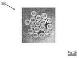
図2に示される第1実施形態では、以下の幾何学的配列を有するコード200を製造した。
In the first embodiment shown in FIG. 2, a
0.12+(5×0.13;5×0.13;5×0.12)8mmS 0.12+ (5 × 0.13; 5 × 0.13; 5 × 0.12) 8 mmS
すなわち、0.12mmのコアフィラメント202が、第1層において、0.13mmの5本のフィラメント204によって囲まれ、このフィラメント204が、第2層の(交互に並んだ0.13mmのフィラメント212および0.12mmのフィラメント210からなる)10本のフィラメントによって囲まれている。このコードに対して、いくつかのフィラメントがコアに対して1つの円上にもはや位置することができなくなるような態様が選択されている。図2a,2bは、コードに沿って異なる箇所で切断されたこのようなコードの断面図である。
That is, a 0.12
d1/d0の比率は、1.08である。コアフィラメントおよび第1層のフィラメントは、8mmの撚り長さにおいて5本のフィラメントがコアを囲むとき、0.13mmの55%の集合間隙が形成されるように選択されている。この間隙は、第2層のフィラメントの1つを捕捉するのに充分な大きさを有しているが、第1層に6本のフィラメントを収容するほど大きくない。第2層の1本のフィラメント、例えば、フィラメント210′が第1層に介入した場合にも、空間が充分ではないので、第1層からフィラメント204′が押し出されることになる。第2層から1本のフィラメントが少なくとも部分的に第1層に介入するので、第2層が未飽和になり、断面図が示しているように、コードは、概して粗い外観を有することになる。コードを解すと、コアフィラメントは、S方向において、8mmの同一撚り長さで、半径が変化するが実質的に螺旋状の変形を呈している。 The ratio of d 1 / d 0 is 1.08. The core filament and the first layer filament are selected such that a 55% collective gap of 0.13 mm is formed when 5 filaments surround the core at a twist length of 8 mm. This gap is large enough to capture one of the filaments in the second layer, but not large enough to accommodate six filaments in the first layer. Even when one filament of the second layer, for example, the filament 210 'intervenes in the first layer, the space is not enough, and the filament 204' is pushed out from the first layer. Since one filament from the second layer at least partially intervenes in the first layer, the second layer becomes unsaturated and the cord will have a generally rough appearance as the cross-sectional view shows. . When the cord is unwound, the core filament exhibits a substantially helical deformation in the S direction with the same twist length of 8 mm, the radius changing.
いくつかのさらなる詳細について述べると、このコードは、亜鉛被覆フィラメントから作製され、その直径は、0.603mmであり、(12mm直径の円形アンビルを有する標準的なマイクロメータによって測定された)最大直径と最小直径との間の差は、0.007mmと極めて大きい。線密度は、1.58g/mである。529Nの破断強度および0.012%と極めて小さい構造伸びが測定されている。 Stated in some further detail, this cord is made from zinc-coated filaments, whose diameter is 0.603 mm, the maximum diameter (measured by a standard micrometer with a 12 mm diameter circular anvil) And the minimum diameter is as large as 0.007 mm. The linear density is 1.58 g / m. A breaking strength of 529 N and a very small structural elongation of 0.012% have been measured.
本発明のコードの利点は、ポリウレタンに埋設して引張り試験を行ったときに、特に顕著になる。具体的には、約12cmの試料コードの両端を、試料を型内に保持し、その型内に溶融ポリウレタンを注入することによって、長さ5cm、幅2cm、高さ1cmのブロックに埋設した。冷却の後、2つのポリウレタンブロックを互いに離れる方向に引っ張り、破断に至る挙動を観察した。参考例として、(1+6+12×0.120mm)型式のコード(層状構造)を用いた。参考コードは、標準的な引張り試験(埋設せず)において、620Nの破断強度を有している。2回の埋設試験を行うことによって、以下の結果が得られた。 The advantage of the cord of the present invention becomes particularly remarkable when a tensile test is performed by embedding in a polyurethane. Specifically, both ends of a sample cord of about 12 cm were embedded in a block having a length of 5 cm, a width of 2 cm, and a height of 1 cm by holding the sample in a mold and injecting molten polyurethane into the mold. After cooling, the two polyurethane blocks were pulled away from each other and the behavior leading to breakage was observed. As a reference example, a (1 + 6 + 12 × 0.120 mm) type cord (layered structure) was used. The reference cord has a breaking strength of 620 N in a standard tensile test (not embedded). The following results were obtained by performing the embedment test twice.
参考コードは、明らかに、効率の悪い強度の挙動を示している。何故なら、コアがポリウレタンに接触していないので、コアに引張力が殆ど作用せず、引張力がコードの外側シースを介してのみコードに伝達されるからである。本発明のコードは、標準試験における破断強度はかなり低いにも拘わらず、良好な実用上での強度を有することを明確に示している。これは、コアフィラメントの良好な固定が得られ、かつ第2層内に第1層が介入し、第2層が未飽和になることによって、ポリウレタンとの良好な接触が得られたことによると言える。なお、標準試験に対して埋設試験での破断強度が増加しているのは、試料の作製中に加えられた熱によって硬化が促進したことによると思われる。このように、本発明のコードは、順次破断の問題を解消することができる。 The reference code clearly shows inefficient strength behavior. This is because since the core is not in contact with the polyurethane, almost no tensile force acts on the core, and the tensile force is transmitted to the cord only through the outer sheath of the cord. The cord of the present invention clearly shows that it has good practical strength even though the breaking strength in the standard test is quite low. This is because good fixing of the core filament was obtained, and the first layer intervened in the second layer, and the second layer became unsaturated, so that good contact with the polyurethane was obtained. I can say that. The reason why the breaking strength in the embedding test is increased with respect to the standard test is thought to be that the hardening is accelerated by the heat applied during the preparation of the sample. Thus, the cord of the present invention can solve the problem of sequential breakage.
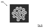
第2の実施形態において、上記の結果を他の幾何学的配列によって確認した。 In the second embodiment, the above results were confirmed by other geometric arrangements.
0.17+(5×0.185;5×0.185;5×0.17)12mmS 0.17+ (5 × 0.185; 5 × 0.185; 5 × 0.17) 12 mmS
第1層における集合間隙は、0.185mm×55.00%として計算することができる。d1/d0の比率は、1.09である。図3a,3b,3cは、コードに沿って数mm間隔で切断した種々の断面300を示している。コアフィラメント302が他のフィラメントから識別されるだろう。第2層のフィラメントは、元々は、交互配列、すなわち、3101→3121→3101→3121→3101→3121→3101→3121→3101→312の順序でコアを取り囲んで、第2の撚合点内に供給されることになる。しかし、この順序は、完全に変化する可能性がある。何故なら、外層のフィラメントは、外層の他の「陥没した」フィラメントを飛び越え、その結果として、例えば、図2aに示される配列、すなわち、3101→3101→3121→3121→3101→3101→3121→3101→3121→312の順序に並ぶ可能性があるからである。
The collective gap in the first layer can be calculated as 0.185 mm × 55.00%. The ratio of d 1 / d 0 is 1.09. Figures 3a, 3b, 3c show various
このコードは、以下の特性、すなわち、3.179g/mの線密度、1107Nの破断強度、2737MPaの有効引張り強度、および194,760MPaの弾性率(180,000MPaの弾性率を有する7×3型または3×3型のストランドコードよりも大きい)を有している。大きな弾性率は、伸びが殆ど許容されない補強用途において、特に有益である。 This cord has the following properties: a linear density of 3.179 g / m, a breaking strength of 1107 N, an effective tensile strength of 2737 MPa, and an elastic modulus of 194,760 MPa (7 × 3 type having an elastic modulus of 180,000 MPa Or larger than a 3 × 3 type strand cord). A large elastic modulus is particularly beneficial in reinforcement applications where little elongation is allowed.
最後に、以下の幾何学的配列による著しく不飽和な第2層を有する実施形態を製造した。 Finally, an embodiment with a highly unsaturated second layer with the following geometry was produced.
0.175+(5×0.20;3×0.20)12mmS 0.175+ (5 × 0.20; 3 × 0.20) 12 mmS
この構造の集合間隙は、0.20mmの45%である。d1/d0の比率は、1.14である。図4は、コードの断面400を示している。この断面において、コアフィラメント402、第1層のフィラメント404、および第2層のフィラメント412の差異が明らかに識別されるだろう。このような断面は、コードを硬質ポリマー成形物内に固定し、この試料を切断し、かつ研磨することによって得られた。層ごとに徐々に研磨することによって、一連の断面を得ることができる。これらの断面から、フィラメント中心(図面では「×」によって示されている)の移動軌跡を再現することができる。成形物内に2つの平行ワイヤ420を導入することによって、基準フレーム422を構築すれば、この基準フレーム422に対するフィラメント中心の位置を測定可能となる。図4bでは、0mm、0.134mm、2.68mm、4.09mm、5.45mm、および6.98mmの箇所における断面、すなわち、撚り長さの約半分の距離における6つの前記断面に基づいて、フィラメント軌跡の変化が示されている。コアフィラメント402の移動軌跡は、「◆」によって示されている。記号を結ぶ線は、便宜的に付けられたものである。明らかに、コアフィラメントは、直線状ではなく、螺旋状の変形を呈している。このような断面に基づいて、図4aでは、「重心」も矢印423によって示されている。この「重心」は、図4bにおいてハッチング領域424で示されるように、フレーム422に対して大きく移動していない。
The collective gap of this structure is 45% of 0.20 mm. The ratio of d 1 / d 0 is 1.14. FIG. 4 shows a
Claims (23)
前記コアフィラメント直径の少なくとも40%でありかつ最大70%の幅を有する集合間隙が、前記第1層のいずれかのフィラメント間に形成されるように、前記撚り長さと、前記コアフィラメント直径と、前記第1層のフィラメント直径とが決定され、前記第2層のいずれかフィラメントが前記集合間隙内に断続的に取り込まれ、前記コアフィラメントが、前記撚り長さおよび撚り方向において実質的に螺旋状に変形されていることを特徴とする鋼コード。 A steel cord for reinforcing an elastomer article, comprising: a core filament having a core filament diameter; and a plurality of filaments arranged around the core filament and having a diameter larger than or equal to the core filament diameter And a second layer of at least one filament disposed around the first layer and having a diameter greater than or equal to the core filament diameter, all of the filaments having the same twist length And those twisted in the same twist direction,
The twist length, the core filament diameter, such that a collective gap having a width of at least 40% and a maximum of 70% of the core filament diameter is formed between any filaments of the first layer; The filament diameter of the first layer is determined, any filament of the second layer is intermittently taken into the assembly gap, and the core filament is substantially helical in the twist length and twist direction Steel cord characterized by being deformed into
スプールに巻かれたコアフィラメントを準備するステップと、
スプールに巻かれた第1層の複数のフィラメントおよび第2層の複数のフィラメントを準備するステップであって、前記第1層の前記複数のフィラメントおよび前記第2層の前記複数のフィラメントが請求項1〜17のいずれか一項に従って選択された直径を有するようなステップと、
前記複数のフィラメントを所定の撚り長さおよび撚り方向で撚り合わせるための回転軸心を有する撚り線機を準備するステップと、
前記各フィラメントを前記各スプールから前記撚り線機に供給するステップであって、第1の撚合点で、前記第1層の前記複数のフィラメントの中心に前記コアフィラメントが導入されて中間ストランドが形成され、更なる撚合点で、前記中間ストランドの周囲に残余の複数のフィラメントが配置されるようなステップと、
を含むものにおいて、
前記コアフィラメントが、前記撚り線機の前記回転軸心に対して静止角度を有して前記第1の撚合点に導入されることを特徴とする方法。 A method of manufacturing a steel cord,
Preparing a core filament wound on a spool;
Preparing a plurality of filaments of a first layer and a plurality of filaments of a second layer wound on a spool, wherein the plurality of filaments of the first layer and the plurality of filaments of the second layer are claimed; Having a diameter selected according to any one of 1-17;
Providing a stranding machine having a rotational axis for twisting the plurality of filaments in a predetermined twisting length and twisting direction;
Supplying each filament from each spool to the stranding machine, wherein the core filament is introduced into the center of the plurality of filaments of the first layer to form an intermediate strand at a first twisting point. A remaining plurality of filaments are disposed around the intermediate strand at a further twist point; and
Including
The method wherein the core filament is introduced at the first twist point with a static angle with respect to the rotational axis of the strand wire machine.
Applications Claiming Priority (3)
| Application Number | Priority Date | Filing Date | Title |
|---|---|---|---|
| EP06077340 | 2006-12-29 | ||
| EP06077340.5 | 2006-12-29 | ||
| PCT/EP2007/063038 WO2008080715A1 (en) | 2006-12-29 | 2007-11-30 | Single lay steel cord for elastomer reinforcement |
Publications (2)
| Publication Number | Publication Date |
|---|---|
| JP2010514947A JP2010514947A (en) | 2010-05-06 |
| JP5378231B2 true JP5378231B2 (en) | 2013-12-25 |
Family
ID=37998413
Family Applications (1)
| Application Number | Title | Priority Date | Filing Date |
|---|---|---|---|
| JP2009543417A Expired - Fee Related JP5378231B2 (en) | 2006-12-29 | 2007-11-30 | Single stranded steel cord for elastomer reinforcement |
Country Status (8)
| Country | Link |
|---|---|
| US (1) | US20100068495A1 (en) |
| EP (1) | EP2097581B1 (en) |
| JP (1) | JP5378231B2 (en) |
| KR (1) | KR101433985B1 (en) |
| CN (1) | CN101573489B (en) |
| BR (1) | BRPI0722065A2 (en) |
| EA (1) | EA015040B1 (en) |
| WO (1) | WO2008080715A1 (en) |
Families Citing this family (12)
| Publication number | Priority date | Publication date | Assignee | Title |
|---|---|---|---|---|
| JP5234954B2 (en) * | 2008-12-05 | 2013-07-10 | 株式会社ブリヂストン | Cord for reinforcing carcass or belt layer of pneumatic tire and pneumatic tire using the same |
| WO2011012454A1 (en) | 2009-07-27 | 2011-02-03 | Nv Bekaert Sa | Hybrid steel-textile reinforcement ply for radial tires |
| KR20120117766A (en) * | 2009-12-01 | 2012-10-24 | 엔브이 베카에르트 에스에이 | A reinforced polymer composite |
| BR112012024795B1 (en) * | 2010-03-30 | 2020-04-22 | Bekaert Advanced Cords Aalter Nv | interlacing that connects a first strip to a second strip and strip containing said interlacing |
| CN102834244B (en) | 2010-03-30 | 2015-03-25 | 贝卡尔特公司 | A splice for jointing steel cord strips encased in thermoplastic material |
| GB2501156B (en) | 2012-02-27 | 2015-03-18 | Gripple Ltd | Improvements in or relating to wire strands |
| FR3051473A1 (en) * | 2016-05-20 | 2017-11-24 | Michelin & Cie | COMPOSITE AND POWER TRANSMISSION BELT |
| CN110799701B (en) | 2017-06-27 | 2022-11-11 | 贝卡尔特先进帘线阿尔特公司 | Reinforcing strand for reinforcing polymer articles |
| US11584619B2 (en) | 2018-01-15 | 2023-02-21 | Otis Elevator Company | Reinforced jacket for belt |
| KR101913074B1 (en) | 2018-05-30 | 2018-12-28 | (주)씨에스 | Method 0f wire rope having enhanced quality properties |
| KR101913075B1 (en) | 2018-05-30 | 2018-10-29 | 조대용 | Wire rope having enhanced quality properties |
| EP4163932A1 (en) * | 2021-10-11 | 2023-04-12 | Nexans | Hvac-cable with composite conductor |
Family Cites Families (14)
| Publication number | Priority date | Publication date | Assignee | Title |
|---|---|---|---|---|
| GB1582647A (en) * | 1977-07-07 | 1981-01-14 | Bekaert Sa Nv | Metal cord |
| DE3561164D1 (en) * | 1984-07-09 | 1988-01-21 | Bekaert Sa Nv | Steel cord twisting structure |
| JPS6233841A (en) * | 1985-08-06 | 1987-02-13 | 東洋ゴム工業株式会社 | Steel cord, its production and steel cord reinforced car tire |
| EP0462716B1 (en) * | 1990-06-16 | 1995-06-28 | Tokusen Kogyo Company Limited | Steel cord for reinforcing rubber product |
| US5609014A (en) * | 1992-04-20 | 1997-03-11 | Tokyo Rope Manufacturing Co., Ltd. | Rubber reinforcing steel cord |
| JPH05302282A (en) * | 1992-04-24 | 1993-11-16 | Bridgestone Corp | Steel cord for reinforcing rubber article and pneumatic radial tire for heavy load |
| WO1995016816A1 (en) * | 1993-12-15 | 1995-06-22 | N.V. Bekaert S.A. | Open steel cord structure |
| DE69516238T2 (en) * | 1994-11-14 | 2000-09-28 | Bridgestone Corp | Steel rope for the reinforcement of elastomeric products |
| EP0834612A1 (en) * | 1996-10-03 | 1998-04-08 | N.V. Bekaert S.A. | Steel cord with a core and a layer |
| US6016647A (en) * | 1998-05-06 | 2000-01-25 | Tokyo Rope Manufacturing Co., Ltd. | Manufacturing method and apparatus of steel cord for rubber product reinforcement |
| EP1033435A1 (en) * | 1999-03-04 | 2000-09-06 | N.V. Bekaert S.A. | Steel cord with polymer core |
| DE60011141T2 (en) * | 1999-12-30 | 2005-01-20 | Société de Technologie Michelin | MULTILAYER STEEL ROPE FOR THE CARKASSE OF A AIR RIM |
| CN2469168Y (en) * | 2001-04-25 | 2002-01-02 | 杭州天海新材料科技有限公司 | High performance oil pumping cable |
| ATE334251T1 (en) * | 2002-02-14 | 2006-08-15 | Bekaert Sa Nv | COMPACT STEEL CABLE |
-
2007
- 2007-11-30 BR BRPI0722065 patent/BRPI0722065A2/en not_active Application Discontinuation
- 2007-11-30 EP EP07847554.8A patent/EP2097581B1/en not_active Not-in-force
- 2007-11-30 US US12/516,637 patent/US20100068495A1/en not_active Abandoned
- 2007-11-30 KR KR1020097013420A patent/KR101433985B1/en not_active IP Right Cessation
- 2007-11-30 EA EA200900902A patent/EA015040B1/en not_active IP Right Cessation
- 2007-11-30 JP JP2009543417A patent/JP5378231B2/en not_active Expired - Fee Related
- 2007-11-30 CN CN200780048767XA patent/CN101573489B/en active Active
- 2007-11-30 WO PCT/EP2007/063038 patent/WO2008080715A1/en active Application Filing
Also Published As
| Publication number | Publication date |
|---|---|
| EA015040B1 (en) | 2011-04-29 |
| EA200900902A1 (en) | 2009-12-30 |
| JP2010514947A (en) | 2010-05-06 |
| CN101573489A (en) | 2009-11-04 |
| WO2008080715A1 (en) | 2008-07-10 |
| KR20090110830A (en) | 2009-10-22 |
| EP2097581B1 (en) | 2016-08-24 |
| BRPI0722065A2 (en) | 2014-04-01 |
| EP2097581A1 (en) | 2009-09-09 |
| CN101573489B (en) | 2012-02-01 |
| KR101433985B1 (en) | 2014-08-25 |
| US20100068495A1 (en) | 2010-03-18 |
Similar Documents
| Publication | Publication Date | Title |
|---|---|---|
| JP5378231B2 (en) | Single stranded steel cord for elastomer reinforcement | |
| EP2697147B1 (en) | Coated rope or belt for elevator systems | |
| JP3598125B2 (en) | Steel cord | |
| KR101491907B1 (en) | Hybrid core rope | |
| CN110799701B (en) | Reinforcing strand for reinforcing polymer articles | |
| JP2006009174A (en) | Covered wire rope | |
| CN112955602B (en) | Steel wire rope, coated steel wire rope and belt comprising steel wire rope | |
| JP3519716B2 (en) | Still cord for rubber reinforcement and method for producing the same | |
| JP7296957B2 (en) | Steel cord for elastomer reinforcement | |
| KR101182725B1 (en) | Fine steel cord with a low structural elongation | |
| RU2740988C1 (en) | Eight-strand steel rope | |
| RU186969U1 (en) | STEEL ROPE WITH POLYMERIC COATING | |
| JP2005213683A (en) | Highly flexing resistant rope and method for producing the same | |
| JP3576706B2 (en) | Steel cord for rubber article reinforcement |
Legal Events
| Date | Code | Title | Description |
|---|---|---|---|
| A621 | Written request for application examination |
Free format text: JAPANESE INTERMEDIATE CODE: A621 Effective date: 20101105 |
|
| A977 | Report on retrieval |
Free format text: JAPANESE INTERMEDIATE CODE: A971007 Effective date: 20121017 |
|
| A131 | Notification of reasons for refusal |
Free format text: JAPANESE INTERMEDIATE CODE: A131 Effective date: 20121026 |
|
| A521 | Written amendment |
Free format text: JAPANESE INTERMEDIATE CODE: A523 Effective date: 20130128 |
|
| TRDD | Decision of grant or rejection written | ||
| A01 | Written decision to grant a patent or to grant a registration (utility model) |
Free format text: JAPANESE INTERMEDIATE CODE: A01 Effective date: 20130830 |
|
| A61 | First payment of annual fees (during grant procedure) |
Free format text: JAPANESE INTERMEDIATE CODE: A61 Effective date: 20130925 |
|
| R150 | Certificate of patent or registration of utility model |
Free format text: JAPANESE INTERMEDIATE CODE: R150 |
|
| S111 | Request for change of ownership or part of ownership |
Free format text: JAPANESE INTERMEDIATE CODE: R313113 |
|
| R350 | Written notification of registration of transfer |
Free format text: JAPANESE INTERMEDIATE CODE: R350 |
|
| R250 | Receipt of annual fees |
Free format text: JAPANESE INTERMEDIATE CODE: R250 |
|
| LAPS | Cancellation because of no payment of annual fees |