EP4163932A1 - Hvac-cable with composite conductor - Google Patents
Hvac-cable with composite conductor Download PDFInfo
- Publication number
- EP4163932A1 EP4163932A1 EP21306424.9A EP21306424A EP4163932A1 EP 4163932 A1 EP4163932 A1 EP 4163932A1 EP 21306424 A EP21306424 A EP 21306424A EP 4163932 A1 EP4163932 A1 EP 4163932A1
- Authority
- EP
- European Patent Office
- Prior art keywords
- power cable
- alloy
- conductor
- steel
- cable according
- Prior art date
- Legal status (The legal status is an assumption and is not a legal conclusion. Google has not performed a legal analysis and makes no representation as to the accuracy of the status listed.)
- Pending
Links
- 239000004020 conductor Substances 0.000 title claims abstract description 130
- 239000002131 composite material Substances 0.000 title description 3
- 230000002787 reinforcement Effects 0.000 claims abstract description 38
- 229910000831 Steel Inorganic materials 0.000 claims abstract description 36
- 239000010959 steel Substances 0.000 claims abstract description 36
- 229910045601 alloy Inorganic materials 0.000 claims abstract description 23
- 239000000956 alloy Substances 0.000 claims abstract description 23
- 239000004411 aluminium Substances 0.000 claims abstract description 15
- 229910052782 aluminium Inorganic materials 0.000 claims abstract description 15
- XAGFODPZIPBFFR-UHFFFAOYSA-N aluminium Chemical compound [Al] XAGFODPZIPBFFR-UHFFFAOYSA-N 0.000 claims abstract description 15
- 238000001556 precipitation Methods 0.000 claims abstract description 4
- 239000000463 material Substances 0.000 claims description 20
- -1 polyethylene Polymers 0.000 claims description 13
- 239000004698 Polyethylene Substances 0.000 claims description 11
- 229920000573 polyethylene Polymers 0.000 claims description 11
- 229920001903 high density polyethylene Polymers 0.000 claims description 10
- 239000004700 high-density polyethylene Substances 0.000 claims description 10
- 229920001684 low density polyethylene Polymers 0.000 claims description 10
- 239000004702 low-density polyethylene Substances 0.000 claims description 10
- 229920001179 medium density polyethylene Polymers 0.000 claims description 10
- 239000004701 medium-density polyethylene Substances 0.000 claims description 10
- 229910052751 metal Inorganic materials 0.000 claims description 10
- 239000002184 metal Substances 0.000 claims description 10
- 229910000838 Al alloy Inorganic materials 0.000 claims description 8
- 229920000642 polymer Polymers 0.000 claims description 8
- OKTJSMMVPCPJKN-UHFFFAOYSA-N Carbon Chemical compound [C] OKTJSMMVPCPJKN-UHFFFAOYSA-N 0.000 claims description 7
- 229920003020 cross-linked polyethylene Polymers 0.000 claims description 6
- 239000004703 cross-linked polyethylene Substances 0.000 claims description 6
- 239000011810 insulating material Substances 0.000 claims description 6
- SMZOUWXMTYCWNB-UHFFFAOYSA-N 2-(2-methoxy-5-methylphenyl)ethanamine Chemical compound COC1=CC=C(C)C=C1CCN SMZOUWXMTYCWNB-UHFFFAOYSA-N 0.000 claims description 5
- NIXOWILDQLNWCW-UHFFFAOYSA-N 2-Propenoic acid Natural products OC(=O)C=C NIXOWILDQLNWCW-UHFFFAOYSA-N 0.000 claims description 5
- 229910000619 316 stainless steel Inorganic materials 0.000 claims description 5
- 229910000881 Cu alloy Inorganic materials 0.000 claims description 5
- VGGSQFUCUMXWEO-UHFFFAOYSA-N Ethene Chemical compound C=C VGGSQFUCUMXWEO-UHFFFAOYSA-N 0.000 claims description 5
- 239000005977 Ethylene Substances 0.000 claims description 5
- 229920010126 Linear Low Density Polyethylene (LLDPE) Polymers 0.000 claims description 5
- CERQOIWHTDAKMF-UHFFFAOYSA-N Methacrylic acid Chemical compound CC(=C)C(O)=O CERQOIWHTDAKMF-UHFFFAOYSA-N 0.000 claims description 5
- OFOBLEOULBTSOW-UHFFFAOYSA-N Propanedioic acid Natural products OC(=O)CC(O)=O OFOBLEOULBTSOW-UHFFFAOYSA-N 0.000 claims description 5
- 229910052799 carbon Inorganic materials 0.000 claims description 5
- 229920001577 copolymer Polymers 0.000 claims description 5
- 239000011888 foil Substances 0.000 claims description 5
- VOZRXNHHFUQHIL-UHFFFAOYSA-N glycidyl methacrylate Chemical compound CC(=C)C(=O)OCC1CO1 VOZRXNHHFUQHIL-UHFFFAOYSA-N 0.000 claims description 5
- VZCYOOQTPOCHFL-UPHRSURJSA-N maleic acid Chemical compound OC(=O)\C=C/C(O)=O VZCYOOQTPOCHFL-UPHRSURJSA-N 0.000 claims description 5
- 239000011976 maleic acid Substances 0.000 claims description 5
- FPYJFEHAWHCUMM-UHFFFAOYSA-N maleic anhydride Chemical compound O=C1OC(=O)C=C1 FPYJFEHAWHCUMM-UHFFFAOYSA-N 0.000 claims description 5
- 239000000178 monomer Substances 0.000 claims description 5
- VZCYOOQTPOCHFL-UHFFFAOYSA-N trans-butenedioic acid Natural products OC(=O)C=CC(O)=O VZCYOOQTPOCHFL-UHFFFAOYSA-N 0.000 claims description 5
- 229920000181 Ethylene propylene rubber Polymers 0.000 claims description 4
- 239000004743 Polypropylene Substances 0.000 claims description 4
- 229920001155 polypropylene Polymers 0.000 claims description 4
- 229920002635 polyurethane Polymers 0.000 claims description 4
- 239000004814 polyurethane Substances 0.000 claims description 4
- 239000004800 polyvinyl chloride Substances 0.000 claims description 4
- 229910001335 Galvanized steel Inorganic materials 0.000 claims description 3
- 229910052802 copper Inorganic materials 0.000 claims description 3
- 239000008397 galvanized steel Substances 0.000 claims description 3
- 238000000265 homogenisation Methods 0.000 claims description 3
- 229910001220 stainless steel Inorganic materials 0.000 claims description 3
- 239000010935 stainless steel Substances 0.000 claims description 3
- 239000010963 304 stainless steel Substances 0.000 claims description 2
- 229920002943 EPDM rubber Polymers 0.000 claims description 2
- 229910000640 Fe alloy Inorganic materials 0.000 claims description 2
- 229910000978 Pb alloy Inorganic materials 0.000 claims description 2
- 229910000589 SAE 304 stainless steel Inorganic materials 0.000 claims description 2
- 229920001971 elastomer Polymers 0.000 claims description 2
- 229910001092 metal group alloy Inorganic materials 0.000 claims description 2
- 229920001169 thermoplastic Polymers 0.000 claims description 2
- 229920001187 thermosetting polymer Polymers 0.000 claims description 2
- 239000004416 thermosoftening plastic Substances 0.000 claims description 2
- 239000012774 insulation material Substances 0.000 claims 1
- 239000011162 core material Substances 0.000 description 24
- 239000010410 layer Substances 0.000 description 23
- XLYOFNOQVPJJNP-UHFFFAOYSA-N water Substances O XLYOFNOQVPJJNP-UHFFFAOYSA-N 0.000 description 19
- 230000004888 barrier function Effects 0.000 description 15
- 238000009413 insulation Methods 0.000 description 14
- 230000003014 reinforcing effect Effects 0.000 description 8
- 229910000975 Carbon steel Inorganic materials 0.000 description 6
- 239000010962 carbon steel Substances 0.000 description 6
- 238000009434 installation Methods 0.000 description 4
- 239000010949 copper Substances 0.000 description 3
- 230000005611 electricity Effects 0.000 description 3
- 239000012212 insulator Substances 0.000 description 3
- 230000035699 permeability Effects 0.000 description 3
- RHZUVFJBSILHOK-UHFFFAOYSA-N anthracen-1-ylmethanolate Chemical compound C1=CC=C2C=C3C(C[O-])=CC=CC3=CC2=C1 RHZUVFJBSILHOK-UHFFFAOYSA-N 0.000 description 2
- 239000003830 anthracite Substances 0.000 description 2
- 239000006229 carbon black Substances 0.000 description 2
- 239000002041 carbon nanotube Substances 0.000 description 2
- 229910021393 carbon nanotube Inorganic materials 0.000 description 2
- 239000003610 charcoal Substances 0.000 description 2
- 229940106265 charcoal Drugs 0.000 description 2
- 239000000571 coke Substances 0.000 description 2
- 230000000694 effects Effects 0.000 description 2
- 230000033001 locomotion Effects 0.000 description 2
- 239000000203 mixture Substances 0.000 description 2
- RYGMFSIKBFXOCR-UHFFFAOYSA-N Copper Chemical compound [Cu] RYGMFSIKBFXOCR-UHFFFAOYSA-N 0.000 description 1
- 240000000491 Corchorus aestuans Species 0.000 description 1
- 235000011777 Corchorus aestuans Nutrition 0.000 description 1
- 235000010862 Corchorus capsularis Nutrition 0.000 description 1
- UFHFLCQGNIYNRP-UHFFFAOYSA-N Hydrogen Chemical compound [H][H] UFHFLCQGNIYNRP-UHFFFAOYSA-N 0.000 description 1
- 150000001875 compounds Chemical class 0.000 description 1
- 230000006835 compression Effects 0.000 description 1
- 238000007906 compression Methods 0.000 description 1
- 238000005336 cracking Methods 0.000 description 1
- 239000003989 dielectric material Substances 0.000 description 1
- 238000009826 distribution Methods 0.000 description 1
- 230000007717 exclusion Effects 0.000 description 1
- 238000000605 extraction Methods 0.000 description 1
- 239000002657 fibrous material Substances 0.000 description 1
- 239000000945 filler Substances 0.000 description 1
- 239000007789 gas Substances 0.000 description 1
- 229910052739 hydrogen Inorganic materials 0.000 description 1
- 239000001257 hydrogen Substances 0.000 description 1
- 229910052742 iron Inorganic materials 0.000 description 1
- 229910052748 manganese Inorganic materials 0.000 description 1
- 238000004519 manufacturing process Methods 0.000 description 1
- 238000010338 mechanical breakdown Methods 0.000 description 1
- 238000000034 method Methods 0.000 description 1
- 238000013508 migration Methods 0.000 description 1
- 230000005012 migration Effects 0.000 description 1
- 229910052759 nickel Inorganic materials 0.000 description 1
- 230000003287 optical effect Effects 0.000 description 1
- 239000011241 protective layer Substances 0.000 description 1
- 238000012216 screening Methods 0.000 description 1
- 238000000926 separation method Methods 0.000 description 1
- 229910000658 steel phase Inorganic materials 0.000 description 1
- 238000012546 transfer Methods 0.000 description 1
- 238000012795 verification Methods 0.000 description 1
- 239000003643 water by type Substances 0.000 description 1
- 238000003466 welding Methods 0.000 description 1
Images


Classifications
-
- H—ELECTRICITY
- H01—ELECTRIC ELEMENTS
- H01B—CABLES; CONDUCTORS; INSULATORS; SELECTION OF MATERIALS FOR THEIR CONDUCTIVE, INSULATING OR DIELECTRIC PROPERTIES
- H01B7/00—Insulated conductors or cables characterised by their form
- H01B7/14—Submarine cables
-
- H—ELECTRICITY
- H01—ELECTRIC ELEMENTS
- H01B—CABLES; CONDUCTORS; INSULATORS; SELECTION OF MATERIALS FOR THEIR CONDUCTIVE, INSULATING OR DIELECTRIC PROPERTIES
- H01B9/00—Power cables
- H01B9/006—Constructional features relating to the conductors
-
- H—ELECTRICITY
- H01—ELECTRIC ELEMENTS
- H01B—CABLES; CONDUCTORS; INSULATORS; SELECTION OF MATERIALS FOR THEIR CONDUCTIVE, INSULATING OR DIELECTRIC PROPERTIES
- H01B1/00—Conductors or conductive bodies characterised by the conductive materials; Selection of materials as conductors
- H01B1/02—Conductors or conductive bodies characterised by the conductive materials; Selection of materials as conductors mainly consisting of metals or alloys
-
- H—ELECTRICITY
- H01—ELECTRIC ELEMENTS
- H01B—CABLES; CONDUCTORS; INSULATORS; SELECTION OF MATERIALS FOR THEIR CONDUCTIVE, INSULATING OR DIELECTRIC PROPERTIES
- H01B3/00—Insulators or insulating bodies characterised by the insulating materials; Selection of materials for their insulating or dielectric properties
- H01B3/18—Insulators or insulating bodies characterised by the insulating materials; Selection of materials for their insulating or dielectric properties mainly consisting of organic substances
- H01B3/30—Insulators or insulating bodies characterised by the insulating materials; Selection of materials for their insulating or dielectric properties mainly consisting of organic substances plastics; resins; waxes
-
- H—ELECTRICITY
- H01—ELECTRIC ELEMENTS
- H01B—CABLES; CONDUCTORS; INSULATORS; SELECTION OF MATERIALS FOR THEIR CONDUCTIVE, INSULATING OR DIELECTRIC PROPERTIES
- H01B7/00—Insulated conductors or cables characterised by their form
- H01B7/08—Flat or ribbon cables
- H01B7/0876—Flat or ribbon cables comprising twisted pairs
-
- H—ELECTRICITY
- H01—ELECTRIC ELEMENTS
- H01B—CABLES; CONDUCTORS; INSULATORS; SELECTION OF MATERIALS FOR THEIR CONDUCTIVE, INSULATING OR DIELECTRIC PROPERTIES
- H01B7/00—Insulated conductors or cables characterised by their form
- H01B7/17—Protection against damage caused by external factors, e.g. sheaths or armouring
- H01B7/18—Protection against damage caused by wear, mechanical force or pressure; Sheaths; Armouring
- H01B7/1805—Protections not provided for in groups H01B7/182 - H01B7/26
-
- H—ELECTRICITY
- H01—ELECTRIC ELEMENTS
- H01B—CABLES; CONDUCTORS; INSULATORS; SELECTION OF MATERIALS FOR THEIR CONDUCTIVE, INSULATING OR DIELECTRIC PROPERTIES
- H01B7/00—Insulated conductors or cables characterised by their form
- H01B7/17—Protection against damage caused by external factors, e.g. sheaths or armouring
- H01B7/18—Protection against damage caused by wear, mechanical force or pressure; Sheaths; Armouring
- H01B7/20—Metal tubes, e.g. lead sheaths
- H01B7/207—Metal tubes, e.g. lead sheaths composed of iron or steel
-
- H—ELECTRICITY
- H01—ELECTRIC ELEMENTS
- H01B—CABLES; CONDUCTORS; INSULATORS; SELECTION OF MATERIALS FOR THEIR CONDUCTIVE, INSULATING OR DIELECTRIC PROPERTIES
- H01B7/00—Insulated conductors or cables characterised by their form
- H01B7/17—Protection against damage caused by external factors, e.g. sheaths or armouring
- H01B7/18—Protection against damage caused by wear, mechanical force or pressure; Sheaths; Armouring
- H01B7/22—Metal wires or tapes, e.g. made of steel
- H01B7/221—Longitudinally placed metal wires or tapes
- H01B7/223—Longitudinally placed metal wires or tapes forming part of a high tensile strength core
-
- H—ELECTRICITY
- H01—ELECTRIC ELEMENTS
- H01B—CABLES; CONDUCTORS; INSULATORS; SELECTION OF MATERIALS FOR THEIR CONDUCTIVE, INSULATING OR DIELECTRIC PROPERTIES
- H01B7/00—Insulated conductors or cables characterised by their form
- H01B7/17—Protection against damage caused by external factors, e.g. sheaths or armouring
- H01B7/18—Protection against damage caused by wear, mechanical force or pressure; Sheaths; Armouring
- H01B7/26—Reduction of losses in sheaths or armouring
-
- H—ELECTRICITY
- H01—ELECTRIC ELEMENTS
- H01B—CABLES; CONDUCTORS; INSULATORS; SELECTION OF MATERIALS FOR THEIR CONDUCTIVE, INSULATING OR DIELECTRIC PROPERTIES
- H01B9/00—Power cables
- H01B9/02—Power cables with screens or conductive layers, e.g. for avoiding large potential gradients
- H01B9/027—Power cables with screens or conductive layers, e.g. for avoiding large potential gradients composed of semi-conducting layers
Definitions
- the present invention relates to a high voltage alternative current cable having mechanically reinforced electric conductor.
- Offshore maritime infrastructures such as e.g. floating wind power installations, offshore oil and gas extraction facilities etc.
- the transfer of electric power between offshore facilities and/or onshore grids/facilities often requires submarine power cables having relatively high mechanical strengths to endure stretching and/or compression forces acting on the cable, especially in cases where the installations are in areas with great water depths.
- Power cables for intermediate to high current capacities have typically one or more electric conductors at its core followed by electric insulation and shielding of the conductors, an inner sheathing protecting the core, armouring layer, and an outer sheathing as shown schematically in figure 1 .
- This embodiment comprises three electric conductors 12, each electrically insulated by an insulation 14.
- An inner sheathing 16 encompasses the three conductors, then follows an armouring 18 and an outer sheathing 19.
- These are the typical minimum of components required to make a functional power cable with comparably high electric power transferring capacity.
- a power cable may however also comprise one or more additional components depending on the intended properties and functionalities of the power cable.
- the conductors of power cables are typically made of either aluminium or copper.
- the conductor may either be monolithic, i.e. made of a single strand surrounded by electric insulating and shielding layers, or a plurality of strands arranged into a bunt being surrounded by electric insulating and shielding layers.
- HVAC high voltage alternative current
- the most commonly applied steel wires are made of ferritic steel which is magnetic.
- the fluctuating magnetic fields radiated by the three electric conductors causes hysteresis and eddy current losses. This magnetic loss may constitute up to about 1/3 of the total loss of electric energy in a power cable.
- EP 2 210 260 discloses an umbilical assembly for supplying power to subsea equipment which includes an electrical conductor to convey an electrical current to the subsea equipment.
- An insulator surrounds the conductor.
- a support member is positioned between the insulator and the conductor.
- the support member has either non-magnetic properties or low-magnetic properties because of its material composition.
- the support member is adapted to connect to a structure at the surface of the sea.
- the support member supports the weight of the conductor.
- the supporting of the weight of the conductor by the support member can be to reduce creep typically associated with the conductor supporting its own weight.
- the support member can be used to hermetically seal the conductor and prevent hydrogen migration along the conductor.
- the main objective of the invention is to provide high voltage alternating current power cable having a composite electric conductor.
- the present invention is the reduction to practice of the realisation that the necessary mechanical integrity and resilience of subsea power cables may be realised without an armouring layer around the cable core, as is commonly applied in prior art cables. Exclusion of the armouring layer around the cable core may yield large manufacturing cost savings. This is obtained by applying electric conductor(s) adapted to provide the mechanical strength and integrity of the power cable.
- the present invention relates to a power cable (1), comprising:
- reinforcement member encompasses any known or conceivable metallic member having a higher mechanical strength/resilience to axial tensions, and thus a higher yield limit, as compared to typical electric conducting materials applied in conductors.
- the metallic member may further be low or non-magnetic.
- the reinforcement member is a mechanical reinforcement of the conductor which enables forming power cables without the conventional armouring typically being laid around the cable core.
- the reinforcement member includes, but is not limited to, low or non-magnetic steel, and/or mechanically resilient Al or Cu alloys such as a CuNiSi precipitation alloy, an EN AW-1xxx, EN AW-2xxx, EN AW-5xxx, AW-6xxx, EN AW-7xxx, or EN AW-8xxx alloy, according to the European aluminium standard.
- the reinforcement member may be a single strand wire, i.e. monolithic wire, or composed of a plurality of wires arranged in a bunt. The plurality of wires may be or may not be twined together.
- low or non-magnetic steel encompasses any steel having magnetic properties comparable to duplex steel or lower, i.e. a magnetic volumetric susceptibility of ⁇ v SI ⁇ 60.
- any austenitic steel or duplex steel may be applied in the reinforcement member.
- suited steels includes, but is not limited to; AL 4565 superaustenitic stainless steel (UNS 34565), AISI 304 Stainless Steel (UNS S30400), AISI 316 Stainless Steel (UNS S31600), duplex steel UNS S31803 (EN 1.4462), super-duplex steel UNS S32750 (EN 1.4410), or lean duplex steel UNS S32304 (EN 1.4362).
- current conducting material encompasses any metal or metal alloy known to the person skilled in the art having an electric conductivity making the metal/alloy suitable for conducting electric currents.
- the electrically conductive material being applied as conductor(s) in power cables may advantageously have an electric conductivity of at least 2.9 ⁇ 10 7 S/m at 20 °C, preferably of at least 5.0 ⁇ 10 7 S/m at 20 °C and most preferably of at least 6 ⁇ 10 7 S/m at 20 °C.
- materials being suited as the current conducting material include, but are not limited to; Cu, Cu-alloy, Al, or an Al-alloy.
- conductor as used herein comprises the current conducting material including an electric insulation around the current conducting material of one electric phase of the power cable.
- a one-phase power cable contains only one conductor, while a three-phase cable contains three conductors.
- the conductor(s) of the present invention comprises further a reinforcement member being embedded in the current conducting material to enhance the mechanical strength of the power cable.
- the power cable according to the invention may comprise three conductors.
- the current conducting material encompasses and embeds the reinforcement member such that the current conducting material forms a shell/layer laid onto and covering the surface of the reinforcement member.
- the shell/layer of current conducting material may be a monolithic shell/layer laid radially around the reinforcement member or consist of a plurality of wires of the current conducting material surrounding the reinforcement member.
- the plurality of wires of the current conducting material may in one embodiment be twined together. In the latter case of applying a plurality of strands of current conducting materials, the space in-between the strands may be occupied by a semiconducting filler compound.
- the above described composite structure of the conductor according to the invention i.e. the reinforcement member at the centre and a layer of current conducting material
- the shell/layer may be formed by wrapping a sheet of the current conducting material around the reinforcement member and seam welding the sheet to form a tube.
- electric insulating material encompasses any known or conceivable material, including dielectric materials, known to the skilled person as being suited as insulation of the current carrying conductor(s) of power cables.
- the electric conductivity of the material being applied as insulation may advantageously have an electric conductivity of less than 10 -14 S/m at 20 °C, preferably less than 10 -16 S/m at 20 °C, preferably less than 10 -18 S/m at 20 °C, and most preferably less than 10 -20 S/m at 20 °C.
- Examples of materials suited for being applied to form the electric insulation of the conductor(s) include, but are not limited to; ethylene propylene rubber (EPR), ethylene propylene diene monomer (EDPM), rubber, polyethylene (EP), polypropylene (PP), polyurethane (PUR), cross-linked polyethylene (XLPE), and mass-impregnated (MI) paper.
- EPR ethylene propylene rubber
- EDPM ethylene propylene diene monomer
- EP polyethylene
- PP polypropylene
- PUR polyurethane
- XLPE cross-linked polyethylene
- MI mass-impregnated
- the conductor may in one embodiment further comprise a semiconducting conductor screen arranged radially around and encompassing the single strand or bunt of strands of the current conducting material.
- semiconductor refers to the material having an electric conductivity intermediate between the conductivity of materials applied as electric conductors and materials applied as electric insulators.
- Examples of suited polymers for use as semiconducting conductor screen includes, but is not limited, to a polyethylene-based material constituted of either low density polyethylene (LDPE), a linear low density polyethylene (LLDPE), a medium density polyethylene (MDPE), or a high density polyethylene (HDPE), or a copolymer of ethylene with one or more polar monomers of; acrylic acid, methacrylic acid, glycidyl methacrylate, maleic acid, or maleic anhydride made semiconducting by addition and homogenisation of until 40 weight% particulate carbon in the polymer mass.
- Examples of suited particulate carbon includes but is not limited to; comminuted petrol coke, comminuted anthracite, comminuted char coal, carbon black, carbon nanotubes, etc.
- the cable core of the power cable refers to the electricity carrying part of the power cable.
- the cable core of the power cable according to the invention comprises at least the one or more hybrid conductors of the power cable, but may alternatively further comprise optical fibres, umbilical tubes, distancing profiles arranging the electric conductors in a circular cross-section and any other component known to be present in a cable core.
- the at least one conductor(s) further comprises an inner sheathing/water barrier having excellent water barrier properties laid outside of the electric insulation of each of the one or more conductors to block any intrusion of water and/or moisture into the current carrying core of the conductor(s).
- the inner sheathing/water barrier may be applied around the cable core, i.e. the power cable comprises a single inner sheathing/water barrier protecting all components of the cable core. In the latter embodiment, the conductor(s) of the power cable has no inner sheathing/water barrier.
- the inner sheathing/water barrier should endure any movements imposed on the power cable by wave motions, under water currents etc. without fatigue, unintended separation between the layers, cracking or any other mechanical breakdown destroying the water barrier function of the inner sheathing during the desired lifetime of the power cable, which may be many years.
- the inner sheathing may advantageously also function as an emergency earthing conductor leading eventual short circuit currents and/or eventual capacitive charging currents in the power cable to ground. I.e. there are rather stringent mechanical requirements imposed on the inner sheathing of power cables such that the inner sheathing is usually a metallic tube of sufficient diameter to house at least the electrically insulated conductor(s).
- the invention is not tied to any inner sheathing/water barrier but may apply any sheathing/water barrier known to the person skilled in the art.
- Examples of suited inner sheathing/water barrier includes, but is not limited to, either:
- the inner sheathing/water barrier may be a laminate of a metal foil/layer as specified above and a polymer, such as e.g. a polyethylene-based material constituted of either low density polyethylene (LDPE), a linear low density polyethylene (LLDPE), a medium density polyethylene (MDPE), or a high density polyethylene (HDPE), or a copolymer of ethylene with one or more polar monomers of; acrylic acid, methacrylic acid, glycidyl methacrylate, maleic acid, or maleic anhydride.
- the polymer may in one embodiment be made semiconducting by addition and homogenisation of 20 to 40 weight% particulate carbon in the polymer mass. Examples of suited particulate carbon includes but is not limited to; comminuted petrol coke, comminuted anthracite, comminuted char coal, carbon black, carbon nanotubes, etc.
- Power cables without armouring are limited by the strength of the conductor material, which will limit the application of the cable.
- armour-less subsea three phase power cables having high strength aluminium alloy conductors have a depth limitation of around 1000 m.
- the use of a reinforcement member in the conductor core increases the mechanical strength of the cable enabling its use in deeper waters.
- the mechanical reinforcement may, in one example embodiment of the power cable, be further increased by also comprising an armouring laid around the cable core.
- the term "cable core" as applied herein refers to the inner current conducting part of the cable which typically comprises the one or more conductors, but may also comprise any other component known to be applied in cable cores such as e.g. distance holders to keep the three conductors of a three-phase cable apart from each other, fibre-optic cables, screening, water barrier, etc.
- the invention is not tied to any specific armouring but may apply any armouring known to the person skilled in the art.
- armouring includes galvanized steel wires, steel tape, braid, sheath or low loss armour etc.
- the armouring will, due to being metallic, also function as emergency earthing conductor. In embodiments with such armouring, the armouring comes in addition to and is not to be confused with the reinforcement member at the centre of each conductor.
- the power cable according to the invention may in one embodiment further comprise a bedding, such as e.g. a swellable tape.
- the bedding is an intermediate layer between the inner sheathing and the armouring, which both typically are metallic, to avoid metal-to-metal contact and the potential mechanical and corrosive problems such contact may arise.
- the bedding may typically be made of fibrous materials such as e.g. jute or hessian tape.
- the invention may apply any known or conceivable material in the bedding known to the skilled person to be suited as bedding.
- outer sheathing refers to the outermost sheathing/- protective layer of the power cable facing the environment.
- the power cable according to the invention is not tied to any specific outer sheathing, but may apply any outer sheathing known or conceivable to the person skilled in the art.
- suited materials include, but is not limited to, a thermoplastic or a thermosetting material such as e.g. polyvinyl chloride (PVC), or a chlorosulphanated polyethylene (CSP).
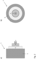
- This example embodiment is a single phase power cable according to the first aspect of the invention which is schematically illustrated in figures 2a) and 2b).
- Figure 2a is an exploded view of an end as seen from the side of the power cable and figure 2b ) is a cut view as seen from the front.
- the power cable 1 of this example embodiment has a reinforcement member 2 made of a bunt of austenitic steel wires of AISI 316 Stainless Steel (UNS S31600) at the centre.
- the steel wire is embedded in a layer 3 of aluminium wires of the AA1120 (UNS A91120) alloy constituting the electric conducting material.
- the cable core in this example embodiment consists of the reinforcement element 2, the electric conducting material 4 and the electric insulation 4.
- Figure 3a) and 3b ) illustrate a similar embodiment with the position of semiconducting conductor screen 4a shown.
- This example embodiment of the power cable according to the first aspect of the invention is a three-phase submarine power cable illustrated schematically in figure 4 ).
- the figure is a cut view as seen from the front.
- the power cable 1 of this example embodiment has three conductors, each consisting of a reinforcement element 2 made of a bunt of austenitic steel wires of AISI 316 Stainless Steel (UNS S31600) at the centre followed by a layer of aluminium wires of the AA1120 (UNS A91120) alloy constituting the electric conducting material 3. Then follows an electric insulation layer 4 of polyethylene (EP).
- a reinforcement element 2 made of a bunt of austenitic steel wires of AISI 316 Stainless Steel (UNS S31600) at the centre followed by a layer of aluminium wires of the AA1120 (UNS A91120) alloy constituting the electric conducting material 3.
- EP polyethylene
- the conductors of the second example embodiment also consisted of an inner sheathing/water barrier 6 made of a CuNiSi-alloy having a composition of from 0.8 to 30 weight% Ni, from 0.1 to 2 weight% Si, from 0.1 to 1.5 weight% Fe, and from 0.1 to 1.5 weight% Mn, based on the total mass of the alloy.
- the three conductors are held in place by distancing profiles 7 providing the cable core (which in this example embodiment comprises the three conductors and the distancing profiles) with a circular cross-section.
- the cable of this example embodiment has an armouring 8 of galvanized steel wires and an outer sheathing 5 made of polyvinyl chloride (PVC).
- PVC polyvinyl chloride
- the calculations were made by applying a two-dimensional modelling based on the Finite Element Method (FEM). The calculations accounted for both skin and proximity effects.
- the comparison embodiments include cables having non-hybrid conductors and cables having hybrid conductors but with reinforcing element (the steel phase) lying on the outside of the conducting material, i.e. an inverse configuration as compared to the hybrid conductor according to the invention which has the reinforcing element at the centre of the conductor.
- each conductor had a first 1.5 mm thick semiconductive sheath laid onto the outer metal phase (either the current conducting material or the reinforcement element, depending on which of them being outside of the other), then followed a 22 mm thick insulation layer of XLPE (cross-linked polyethylene), a second 1.5 mm thick semiconductive sheath, and then a 2.2 mm thick lead sheath as water barrier.
- the current conducting material in all example embodiments was an aluminium alloy AA1120 (UNS A91120) defined to have a resistivity of 2.89766 ⁇ 10 -8 [Ohm-m] and a relative magnetic permeability of 1.
- the reinforcement element was either made of a carbon steel assumed to have a resistivity of 2.00 ⁇ 10 -7 [Ohm-m] and a relative magnetic permeability of 700, or made of AISI 316 Stainless Steel (UNS S31600) assumed to have a resistivity of 7.40 ⁇ 10 -7 [Ohm-m] and a relative magnetic permeability of 1.
- the carbon steel applied as comparison reinforcement element is a hypothetical carbon steel ally having electric and magnetic properties close to a G34-series carbon steel and is thus denote as G34 in table 1.
- the cores are set to carry balanced three-phase current of 1000 A at 50 Hz.
- the current distribution between inner core material and the conductor material is determined. A conductor temperature of 90 °C is assumed.
- Table 1 informs further that otherwise equal configurations except for applying a magnetic or a low or non-magnetic steel as the reinforcing element, typically gives a difference in the AC resistivities of 0.4 to 0.6 %.
- the AC resistivity when applying a reinforcing element of SS316 (case 3) at the centre of the conductor is 0.49 percent less than the AC resistivity when applying a reinforcing element of carbon steel (case2).
- a similar result of 0.65 % reduction in the AC resistivity when applying SS316 steel is obtained between cases 4 and 5. This verifies that there is somewhat less power loss when applying a low-magnetic or non-magnetic steel in the reinforcing element of the hybrid conductor according to the invention.
- a significantly larger difference between the AC resistivities (and thus the power loss) is observed when comparing the hybrid conductor according to the invention having the reinforcement element at the centre of the conductor with an "inverse" configuration where the current conducting wires are at the centre and the reinforcement element is laid onto the current conducting wires.
- the difference between the AC resistivities of e.g. cases 3 and 7, i.e. with SS316 steel at the core or on the outside is 2.25 % when the steel is at the core.
- a comparison between cases 5 and 9 gives 2.9 % reduction is the SS316 steel is located at the centre.
Abstract
Description
- The present invention relates to a high voltage alternative current cable having mechanically reinforced electric conductor.
- Offshore maritime infrastructures such as e.g. floating wind power installations, offshore oil and gas extraction facilities etc., may be electrically connected to e.g. subsea installations on the seabed, floating installations, on-shore electricity grids etc. The transfer of electric power between offshore facilities and/or onshore grids/facilities often requires submarine power cables having relatively high mechanical strengths to endure stretching and/or compression forces acting on the cable, especially in cases where the installations are in areas with great water depths.
- Power cables for intermediate to high current capacities have typically one or more electric conductors at its core followed by electric insulation and shielding of the conductors, an inner sheathing protecting the core, armouring layer, and an outer sheathing as shown schematically in
figure 1 . This embodiment comprises threeelectric conductors 12, each electrically insulated by aninsulation 14. Aninner sheathing 16 encompasses the three conductors, then follows an armouring 18 and anouter sheathing 19. These are the typical minimum of components required to make a functional power cable with comparably high electric power transferring capacity. In the case of submarine power cables, it is necessary to include a water barrier around each electric conductor and/or around the core of the cable. A power cable may however also comprise one or more additional components depending on the intended properties and functionalities of the power cable. - The conductors of power cables are typically made of either aluminium or copper. The conductor may either be monolithic, i.e. made of a single strand surrounded by electric insulating and shielding layers, or a plurality of strands arranged into a bunt being surrounded by electric insulating and shielding layers.
- The armouring of high voltage alternative current (HVAC) cables are typically made of steel wires wound in one or more layers around the cable core containing the electrically insulated conductor(s).
- However, the most commonly applied steel wires are made of ferritic steel which is magnetic. In a three-phase AC power cable, the fluctuating magnetic fields radiated by the three electric conductors causes hysteresis and eddy current losses. This magnetic loss may constitute up to about 1/3 of the total loss of electric energy in a power cable.
-
-
EP 2 210 260 - The main objective of the invention is to provide high voltage alternating current power cable having a composite electric conductor.
- The present invention is the reduction to practice of the realisation that the necessary mechanical integrity and resilience of subsea power cables may be realised without an armouring layer around the cable core, as is commonly applied in prior art cables. Exclusion of the armouring layer around the cable core may yield large manufacturing cost savings. This is obtained by applying electric conductor(s) adapted to provide the mechanical strength and integrity of the power cable.
- Thus, in a first aspect, the present invention relates to a power cable (1), comprising:
- at least one conductor having a longitudinal centre axis and an outer sheathing encompassing the at least one conductor, wherein each of the at least one conductor comprises:
- a current conducting material (3), and
- an electric insulating material (4) enclosing the current conducting material (3), and
- the at least one conductor further comprises a reinforcement member (2) located at the longitudinal centre axis of the conductor and where reinforcement member is embedded in and enclosed by the current conducting material (3), and where the reinforcement member is made of either:
- one or more steel wires,
- one or more wires of CuNiSi precipitation alloy, or
- one or more aluminium wires made of an EN AW-1xxx, EN AW-2xxx, EN AW-5xxx, AW-6xxx, EN AW-7xxx, or EN AW-8xxx alloy, according to the European aluminium standard.
- The term "reinforcement member" as used herein encompasses any known or conceivable metallic member having a higher mechanical strength/resilience to axial tensions, and thus a higher yield limit, as compared to typical electric conducting materials applied in conductors. The metallic member may further be low or non-magnetic. Thus, the reinforcement member is a mechanical reinforcement of the conductor which enables forming power cables without the conventional armouring typically being laid around the cable core. Examples of suited materials for the reinforcement member includes, but is not limited to, low or non-magnetic steel, and/or mechanically resilient Al or Cu alloys such as a CuNiSi precipitation alloy, an EN AW-1xxx, EN AW-2xxx, EN AW-5xxx, AW-6xxx, EN AW-7xxx, or EN AW-8xxx alloy, according to the European aluminium standard. The reinforcement member may be a single strand wire, i.e. monolithic wire, or composed of a plurality of wires arranged in a bunt. The plurality of wires may be or may not be twined together.
- The term "low or non-magnetic steel" as used herein encompasses any steel having magnetic properties comparable to duplex steel or lower, i.e. a magnetic volumetric susceptibility of χv SI < 60. Thus, any austenitic steel or duplex steel may be applied in the reinforcement member. Examples of suited steels includes, but is not limited to; AL 4565 superaustenitic stainless steel (UNS 34565), AISI 304 Stainless Steel (UNS S30400), AISI 316 Stainless Steel (UNS S31600), duplex steel UNS S31803 (EN 1.4462), super-duplex steel UNS S32750 (EN 1.4410), or lean duplex steel UNS S32304 (EN 1.4362).
- The term "current conducting material" as used herein, encompasses any metal or metal alloy known to the person skilled in the art having an electric conductivity making the metal/alloy suitable for conducting electric currents. In practice, the electrically conductive material being applied as conductor(s) in power cables may advantageously have an electric conductivity of at least 2.9·107 S/m at 20 °C, preferably of at least 5.0·107 S/m at 20 °C and most preferably of at least 6·107 S/m at 20 °C. Examples of materials being suited as the current conducting material include, but are not limited to; Cu, Cu-alloy, Al, or an Al-alloy.
- The term "conductor" as used herein comprises the current conducting material including an electric insulation around the current conducting material of one electric phase of the power cable. Thus, a one-phase power cable contains only one conductor, while a three-phase cable contains three conductors. In addition, the conductor(s) of the present invention comprises further a reinforcement member being embedded in the current conducting material to enhance the mechanical strength of the power cable. In one embodiment, the power cable according to the invention may comprise three conductors.
- In the conductor(s) according to the present invention, the current conducting material encompasses and embeds the reinforcement member such that the current conducting material forms a shell/layer laid onto and covering the surface of the reinforcement member. The shell/layer of current conducting material may be a monolithic shell/layer laid radially around the reinforcement member or consist of a plurality of wires of the current conducting material surrounding the reinforcement member. The plurality of wires of the current conducting material may in one embodiment be twined together. In the latter case of applying a plurality of strands of current conducting materials, the space in-between the strands may be occupied by a semiconducting filler compound.
- The above described composite structure of the conductor according to the invention, i.e. the reinforcement member at the centre and a layer of current conducting material, may be obtained in any manner known or conceivable to the skilled person. For example, in the case of a monolithic shell/layer of current conducting material, the shell/layer may be formed by wrapping a sheet of the current conducting material around the reinforcement member and seam welding the sheet to form a tube.
- The term "electric insulating material" as used herein, encompasses any known or conceivable material, including dielectric materials, known to the skilled person as being suited as insulation of the current carrying conductor(s) of power cables. In practice the electric conductivity of the material being applied as insulation may advantageously have an electric conductivity of less than 10-14 S/m at 20 °C, preferably less than 10-16 S/m at 20 °C, preferably less than 10-18 S/m at 20 °C, and most preferably less than 10-20 S/m at 20 °C. Examples of materials suited for being applied to form the electric insulation of the conductor(s) include, but are not limited to; ethylene propylene rubber (EPR), ethylene propylene diene monomer (EDPM), rubber, polyethylene (EP), polypropylene (PP), polyurethane (PUR), cross-linked polyethylene (XLPE), and mass-impregnated (MI) paper. The insulation effect of the insulating material depends on the thickness of the layer of insulating material. In general, the higher voltage of the electric current in the conductor, the more insulation is needed. The determination of amount of insulating material required to electrically insulate a conductor is within the ordinary skills of the person skilled in the art.
- The conductor may in one embodiment further comprise a semiconducting conductor screen arranged radially around and encompassing the single strand or bunt of strands of the current conducting material. The term "semiconducting" as used herein, refers to the material having an electric conductivity intermediate between the conductivity of materials applied as electric conductors and materials applied as electric insulators. Examples of suited polymers for use as semiconducting conductor screen includes, but is not limited, to a polyethylene-based material constituted of either low density polyethylene (LDPE), a linear low density polyethylene (LLDPE), a medium density polyethylene (MDPE), or a high density polyethylene (HDPE), or a copolymer of ethylene with one or more polar monomers of; acrylic acid, methacrylic acid, glycidyl methacrylate, maleic acid, or maleic anhydride made semiconducting by addition and homogenisation of until 40 weight% particulate carbon in the polymer mass. Examples of suited particulate carbon includes but is not limited to; comminuted petrol coke, comminuted anthracite, comminuted char coal, carbon black, carbon nanotubes, etc.
- The term "cable core" as applied herein refers to the electricity carrying part of the power cable. Thus, the cable core of the power cable according to the invention comprises at least the one or more hybrid conductors of the power cable, but may alternatively further comprise optical fibres, umbilical tubes, distancing profiles arranging the electric conductors in a circular cross-section and any other component known to be present in a cable core.
- The electric conductors and their electric insulation may need protection towards intrusion of water/moisture. An ingress of moisture into the electricity carrying parts of the cable may lead to a failure of the cable. This is especially important for power cables applied in aqueous environments. Thus, in one embodiment, the at least one conductor(s) further comprises an inner sheathing/water barrier having excellent water barrier properties laid outside of the electric insulation of each of the one or more conductors to block any intrusion of water and/or moisture into the current carrying core of the conductor(s). Alternatively, the inner sheathing/water barrier may be applied around the cable core, i.e. the power cable comprises a single inner sheathing/water barrier protecting all components of the cable core. In the latter embodiment, the conductor(s) of the power cable has no inner sheathing/water barrier.
- The inner sheathing/water barrier should endure any movements imposed on the power cable by wave motions, under water currents etc. without fatigue, unintended separation between the layers, cracking or any other mechanical breakdown destroying the water barrier function of the inner sheathing during the desired lifetime of the power cable, which may be many years. The inner sheathing may advantageously also function as an emergency earthing conductor leading eventual short circuit currents and/or eventual capacitive charging currents in the power cable to ground. I.e. there are rather stringent mechanical requirements imposed on the inner sheathing of power cables such that the inner sheathing is usually a metallic tube of sufficient diameter to house at least the electrically insulated conductor(s).
- The invention is not tied to any inner sheathing/water barrier but may apply any sheathing/water barrier known to the person skilled in the art. Examples of suited inner sheathing/water barrier includes, but is not limited to, either:
- a metal foil/layer of:
- a) Al or an Al-alloy of an AA1xxx series, an AA5xxx series or an AA6xxx series alloy according to the Aluminium Association Standard,
- b) Cu or a Cu-alloy, a CuNi-alloy, or a CuNiSi-alloy,
- c) Fe or a Fe-alloy, a SS316 alloy or a S32750 alloy according to the ASTM A240/A240M-20a standard, or
- d) Pb or a Pb-alloy,
- a laminate of a metal foil/layer of:
- one of a), b), c) or d) and a polyethylene-based polymer chosen from one of; a low density polyethylene (LDPE), a linear low density polyethylene (LLDPE), a medium density polyethylene (MDPE), or a high density polyethylene (HDPE), or
- a copolymer of ethylene with one or more polar monomers of; acrylic acid, methacrylic acid, glycidyl methacrylate, maleic acid, or maleic anhydride.
- In one embodiment, the inner sheathing/water barrier may be a laminate of a metal foil/layer as specified above and a polymer, such as e.g. a polyethylene-based material constituted of either low density polyethylene (LDPE), a linear low density polyethylene (LLDPE), a medium density polyethylene (MDPE), or a high density polyethylene (HDPE), or a copolymer of ethylene with one or more polar monomers of; acrylic acid, methacrylic acid, glycidyl methacrylate, maleic acid, or maleic anhydride. The polymer may in one embodiment be made semiconducting by addition and homogenisation of 20 to 40 weight% particulate carbon in the polymer mass. Examples of suited particulate carbon includes but is not limited to; comminuted petrol coke, comminuted anthracite, comminuted char coal, carbon black, carbon nanotubes, etc.
- Power cables without armouring are limited by the strength of the conductor material, which will limit the application of the cable. For example, armour-less subsea three phase power cables having high strength aluminium alloy conductors have a depth limitation of around 1000 m. The use of a reinforcement member in the conductor core increases the mechanical strength of the cable enabling its use in deeper waters. The mechanical reinforcement may, in one example embodiment of the power cable, be further increased by also comprising an armouring laid around the cable core. The term "cable core" as applied herein refers to the inner current conducting part of the cable which typically comprises the one or more conductors, but may also comprise any other component known to be applied in cable cores such as e.g. distance holders to keep the three conductors of a three-phase cable apart from each other, fibre-optic cables, screening, water barrier, etc.
- The invention is not tied to any specific armouring but may apply any armouring known to the person skilled in the art. Examples of suited armouring includes galvanized steel wires, steel tape, braid, sheath or low loss armour etc. The armouring will, due to being metallic, also function as emergency earthing conductor. In embodiments with such armouring, the armouring comes in addition to and is not to be confused with the reinforcement member at the centre of each conductor.
- The power cable according to the invention may in one embodiment further comprise a bedding, such as e.g. a swellable tape. The bedding is an intermediate layer between the inner sheathing and the armouring, which both typically are metallic, to avoid metal-to-metal contact and the potential mechanical and corrosive problems such contact may arise. The bedding may typically be made of fibrous materials such as e.g. jute or hessian tape. The invention may apply any known or conceivable material in the bedding known to the skilled person to be suited as bedding.
- The term "outer sheathing" as applied herein, refers to the outermost sheathing/- protective layer of the power cable facing the environment. The power cable according to the invention is not tied to any specific outer sheathing, but may apply any outer sheathing known or conceivable to the person skilled in the art. Examples of suited materials include, but is not limited to, a thermoplastic or a thermosetting material such as e.g. polyvinyl chloride (PVC), or a chlorosulphanated polyethylene (CSP).
-
-
Figure 1 is a drawing seen from the side of a typical prior art three-phase power cable. -
Figure 2a) and 2b ) are drawings seen respectively from the side and front of a one-phase example embodiment of the power cable according to the invention. -
Figure 3a) and 3b ) are drawings seen respectively from the side and front of a one-phase example embodiment of the power cable according to the invention. -
Figure 4 is a drawing as seen from the front of an example embodiment of a three-phase power cable according to the invention. - This example embodiment is a single phase power cable according to the first aspect of the invention which is schematically illustrated in
figures 2a) and 2b). Figure 2a ) is an exploded view of an end as seen from the side of the power cable andfigure 2b ) is a cut view as seen from the front. - The
power cable 1 of this example embodiment has areinforcement member 2 made of a bunt of austenitic steel wires of AISI 316 Stainless Steel (UNS S31600) at the centre. The steel wire is embedded in alayer 3 of aluminium wires of the AA1120 (UNS A91120) alloy constituting the electric conducting material. Then follows anelectric insulation 4 of polyethylene (EP) and anouter sheathing 5 made of polyvinyl chloride (PVC). The cable core in this example embodiment consists of thereinforcement element 2, theelectric conducting material 4 and theelectric insulation 4. -
Figure 3a) and 3b ) illustrate a similar embodiment with the position ofsemiconducting conductor screen 4a shown. - This example embodiment of the power cable according to the first aspect of the invention is a three-phase submarine power cable illustrated schematically in
figure 4 ). The figure is a cut view as seen from the front. - The
power cable 1 of this example embodiment has three conductors, each consisting of areinforcement element 2 made of a bunt of austenitic steel wires of AISI 316 Stainless Steel (UNS S31600) at the centre followed by a layer of aluminium wires of the AA1120 (UNS A91120) alloy constituting theelectric conducting material 3. Then follows anelectric insulation layer 4 of polyethylene (EP). In contrast to the conductor of the first example embodiment, the conductors of the second example embodiment also consisted of an inner sheathing/water barrier 6 made of a CuNiSi-alloy having a composition of from 0.8 to 30 weight% Ni, from 0.1 to 2 weight% Si, from 0.1 to 1.5 weight% Fe, and from 0.1 to 1.5 weight% Mn, based on the total mass of the alloy. The three conductors are held in place by distancing profiles 7 providing the cable core (which in this example embodiment comprises the three conductors and the distancing profiles) with a circular cross-section. - Outside of the cable core, the cable of this example embodiment has an
armouring 8 of galvanized steel wires and anouter sheathing 5 made of polyvinyl chloride (PVC). - Numerical calculations have been carried out on embodiments according to the invention and comparison embodiments of 245 kV three-phase power cables to investigate the power loss (AC resistance).
- The calculations were made by applying a two-dimensional modelling based on the Finite Element Method (FEM). The calculations accounted for both skin and proximity effects. The comparison embodiments include cables having non-hybrid conductors and cables having hybrid conductors but with reinforcing element (the steel phase) lying on the outside of the conducting material, i.e. an inverse configuration as compared to the hybrid conductor according to the invention which has the reinforcing element at the centre of the conductor.
- Common to all example embodiments applied in the calculations is that each conductor had a first 1.5 mm thick semiconductive sheath laid onto the outer metal phase (either the current conducting material or the reinforcement element, depending on which of them being outside of the other), then followed a 22 mm thick insulation layer of XLPE (cross-linked polyethylene), a second 1.5 mm thick semiconductive sheath, and then a 2.2 mm thick lead sheath as water barrier. The current conducting material in all example embodiments was an aluminium alloy AA1120 (UNS A91120) defined to have a resistivity of 2.89766·10-8 [Ohm-m] and a relative magnetic permeability of 1. The reinforcement element was either made of a carbon steel assumed to have a resistivity of 2.00·10-7 [Ohm-m] and a relative magnetic permeability of 700, or made of AISI 316 Stainless Steel (UNS S31600) assumed to have a resistivity of 7.40·10-7 [Ohm-m] and a relative magnetic permeability of 1. The carbon steel applied as comparison reinforcement element is a hypothetical carbon steel ally having electric and magnetic properties close to a G34-series carbon steel and is thus denote as G34 in table 1. In the model the cores are set to carry balanced three-phase current of 1000 A at 50 Hz. Upon solving the FEM-model, the current distribution between inner core material and the conductor material is determined. A conductor temperature of 90 °C is assumed.
- Both the current conducting material and the reinforcing element in these example embodiments consisted of wires stranded together, the different configurations of the hybrid conductors applied in the calculations are summarized and the calculated AC resistivities are given in table 1:
Table 1 Configuration of wires in the conductors applied in the calculations Inner wires Outer wires Calculated AC resistivity [Ohm/km] Material Diam. [mm] # of wires Material Diam. [mm] # of wires Case 1 11201) 4.10 91 - - - 0.0348 Case 2G342) 4.10 19 1120 4.10 72 0.04104 Case 3SS3163) 4.10 19 1120 4.10 72 0.04077 Case 4G34 2.08 62 1120 3.68 113 0.03348 Case 5SS316 2.08 62 1120 3.68 113 0.03332 Case 61120 4.10 19 G34 4.10 72 0.04719 Case 7 1120 4.10 19 SS316 4.10 72 0.04169 Case 81120 2.08 62 G34 3.68 113 0.03768 Case 9 1120 2.08 62 SS316 3.68 113 0.03430 1) ASTM AA1120 aluminium alloy (UNS A91120)
2) Carbon steel close to G34 series
3) ASTM SS316 stainless steel (UNS S31600) - A comparison between the calculated AC resistances of
case 1 of table 1 (a three-phase power cable having non-hybrid conductors of only aluminium AA1120 wires) andcases - Table 1 informs further that otherwise equal configurations except for applying a magnetic or a low or non-magnetic steel as the reinforcing element, typically gives a difference in the AC resistivities of 0.4 to 0.6 %. For example, the AC resistivity when applying a reinforcing element of SS316 (case 3) at the centre of the conductor is 0.49 percent less than the AC resistivity when applying a reinforcing element of carbon steel (case2). A similar result of 0.65 % reduction in the AC resistivity when applying SS316 steel is obtained between
cases - A significantly larger difference between the AC resistivities (and thus the power loss) is observed when comparing the hybrid conductor according to the invention having the reinforcement element at the centre of the conductor with an "inverse" configuration where the current conducting wires are at the centre and the reinforcement element is laid onto the current conducting wires. The difference between the AC resistivities of
e.g. cases 3 and 7, i.e. with SS316 steel at the core or on the outside is 2.25 % when the steel is at the core. A comparison betweencases 5 and 9 gives 2.9 % reduction is the SS316 steel is located at the centre. - The results above show that there is a significant reduction in the power loss of three-phase power cables obtained by applying a reinforcing element of low magnetic or non-magnetic steel and locating it at the centre of the conductors.
Claims (14)
- A power cable (1), comprising:at least one conductor having a longitudinal centre axis and an outer sheathing encompassing the at least one conductor, wherein each of the at least one conductor comprises:a current conducting material (3), andan electric insulating material (4) enclosing the current conducting material (3), andcharacterised in thatthe at least one conductor further comprises a reinforcement member (2) located at the longitudinal centre axis of the conductor and where reinforcement member is embedded in and enclosed by the current conducting material (3), and where the reinforcement member is made of either:- one or more steel wires,- one or more wires of CuNiSi precipitation alloy, or- one or more aluminium wires made of an EN AW-1xxx, EN AW-2xxx, EN AW-5xxx, AW-6xxx, EN AW-7xxx, or EN AW-8xxx alloy, according to the European aluminium standard.
- The power cable according to claim 1, wherein the power cable comprises three conductors.
- The power cable according to claim 1 or 2, wherein the reinforcement member (2) is made of a low or non-magnetic steel.
- The power cable according to claim 3, wherein the low or non-magnetic steel is chosen from one of; an austenitic steel or a duplex steel, preferably one of AL 4565 superaustenitic stainless steel (UNS 34565), AISI 304 Stainless Steel (UNS S30400), AISI 316 Stainless Steel (UNS S31600), duplex steel UNS S31803 (EN 1.4462), super-duplex steel UNS S32750 (EN 1.4410), or lean duplex steel UNS S32304 (EN 1.4362).
- The power cable according to any preceding claim, wherein the reinforcement member (2) is either a single monolithic wire or is composed of a plurality of twined or not twined wires arranged in a bunt.
- The power cable according to any preceding claim, wherein the current conducting material (3) is a metal or metal alloy having an electric conductivity of at least 2.9·107 S/m at 20 °C, preferably of at least 5.0·107 S/m at 20 °C and most preferably of at least 6·107 S/m at 20 °C.
- The power cable according to claim 6, wherein the current conducting material (3) is one of: Cu, Cu-alloy, Al, or an Al-alloy.
- The power cable according to claim 6 or 7, wherein the current conducting material (3) is a monolithic shell/layer laid radially around the reinforcement member (2) or consist of a plurality of wires of the current conducting material surrounding the reinforcement member.
- The power cable according to any preceding claim, where the electric insulation material (4) is made of one of; ethylene propylene rubber (EPR), ethylene propylene diene monomer (EDPM), rubber, polyethylene (EP), polypropylene (PP), polyurethane (PUR), cross-linked polyethylene (XLPE), or mass-impregnated (MI) paper.
- The power cable according to any preceding claim, where the power cable further comprises a semiconducting conductor screen (4a) arranged radially around the current conducting material (3), and where the semiconducting conductor screen is made of a polyethylene-based material constituted of either low density polyethylene (LDPE), a linear low density polyethylene (LLDPE), a medium density polyethylene (MDPE), or a high density polyethylene (HDPE), or a copolymer of ethylene with one or more polar monomers of; acrylic acid, methacrylic acid, glycidyl methacrylate, maleic acid, or maleic anhydride made semiconducting by addition and homogenisation of until 40 weight% particulate carbon in the polymer mass.
- The power cable according to any preceding claim, where the power cable further comprises an inner sheathing (6) laid either as an outermost layer of each conductor of the cable or laid around a cable core, and wherein the inner sheathing is made of eithera metal foil/layer of:a) Al or an Al-alloy of an AA1xxx series, an AA5xxx series or an AA6xxx series alloy according to the Aluminium Association Standard,b) Cu or a Cu-alloy, a CuNi-alloy, or a CuNiSi-alloy,c) Fe or a Fe-alloy, a SS316 alloy or a S32750 alloy according to the ASTM A240/A240M-20a standard, ord) Pb or a Pb-alloy,ora laminate of a metal foil/layer of:one of a), b), c) or d) and a polyethylene-based polymer chosen from one of; a low density polyethylene (LDPE), a linear low density polyethylene (LLDPE), a medium density polyethylene (MDPE), or a high density polyethylene (HDPE), ora copolymer of ethylene with one or more polar monomers of; acrylic acid, methacrylic acid, glycidyl methacrylate, maleic acid, or maleic anhydride.
- The power cable according to any preceding claim, where the power cable further comprises an armouring (8) laid around a cable core.
- The power cable according to claim 12, where the armouring (8) is one of: galvanized steel wires, steel tape, braid, sheath, or low loss armour.
- The power cable according to any preceding claim, where the outer sheathing (5) is made of a thermoplastic or a thermosetting material chosen from a polyvinyl chloride (PVC) or a chlorosulphanated polyethylene (CSP).
Priority Applications (2)
| Application Number | Priority Date | Filing Date | Title |
|---|---|---|---|
| EP21306424.9A EP4163932A1 (en) | 2021-10-11 | 2021-10-11 | Hvac-cable with composite conductor |
| US17/960,686 US20230178268A1 (en) | 2021-10-11 | 2022-10-05 | HVAC-cable with composite conductor |
Applications Claiming Priority (1)
| Application Number | Priority Date | Filing Date | Title |
|---|---|---|---|
| EP21306424.9A EP4163932A1 (en) | 2021-10-11 | 2021-10-11 | Hvac-cable with composite conductor |
Publications (1)
| Publication Number | Publication Date |
|---|---|
| EP4163932A1 true EP4163932A1 (en) | 2023-04-12 |
Family
ID=78414611
Family Applications (1)
| Application Number | Title | Priority Date | Filing Date |
|---|---|---|---|
| EP21306424.9A Pending EP4163932A1 (en) | 2021-10-11 | 2021-10-11 | Hvac-cable with composite conductor |
Country Status (2)
| Country | Link |
|---|---|
| US (1) | US20230178268A1 (en) |
| EP (1) | EP4163932A1 (en) |
Citations (4)
| Publication number | Priority date | Publication date | Assignee | Title |
|---|---|---|---|---|
| US20070237469A1 (en) * | 2006-02-17 | 2007-10-11 | Olsen Espen | Electric submarine power cable and system for direct electric heating |
| EP2210260A1 (en) | 2007-11-13 | 2010-07-28 | Chevron U.S.A. Inc. | Subsea power umbilical |
| CN201725627U (en) * | 2010-03-29 | 2011-01-26 | 浙江省电力公司舟山电力局 | Undersea power cable |
| EP2812457A1 (en) | 2012-02-06 | 2014-12-17 | NV Bekaert SA | Non-magnetic stainless steel wire as an armouring wire for power cables |
Family Cites Families (8)
| Publication number | Priority date | Publication date | Assignee | Title |
|---|---|---|---|---|
| BRPI0722065A2 (en) * | 2006-12-29 | 2014-04-01 | Bekaert Sa Nv | SINGLE ARRANGING STEEL CORD FOR ELASTOMER REINFORCEMENT |
| FR3021451B1 (en) * | 2014-05-20 | 2017-12-15 | Nexans | ELECTRICAL CABLE COMPRISING A RETICULATED LAYER |
| US10764541B2 (en) * | 2014-12-15 | 2020-09-01 | SeeScan, Inc. | Coaxial video push-cables for use in inspection systems |
| GB2539894B (en) * | 2015-06-29 | 2019-03-27 | Optasense Holdings Ltd | Monitoring of power cables |
| CN108475561B (en) * | 2015-11-13 | 2020-03-17 | 普睿司曼股份公司 | Power cable with corrosion-resistant armor |
| KR20200004061A (en) * | 2018-07-03 | 2020-01-13 | 엘에스전선 주식회사 | Power cable |
| WO2020057947A1 (en) * | 2018-09-21 | 2020-03-26 | Nv Bekaert Sa | Electric power transmission cable |
| KR20200070788A (en) * | 2018-12-10 | 2020-06-18 | 넥쌍 | High-shielding light-weight cables including shielding layer of polymer-carbon composite |
-
2021
- 2021-10-11 EP EP21306424.9A patent/EP4163932A1/en active Pending
-
2022
- 2022-10-05 US US17/960,686 patent/US20230178268A1/en active Pending
Patent Citations (4)
| Publication number | Priority date | Publication date | Assignee | Title |
|---|---|---|---|---|
| US20070237469A1 (en) * | 2006-02-17 | 2007-10-11 | Olsen Espen | Electric submarine power cable and system for direct electric heating |
| EP2210260A1 (en) | 2007-11-13 | 2010-07-28 | Chevron U.S.A. Inc. | Subsea power umbilical |
| CN201725627U (en) * | 2010-03-29 | 2011-01-26 | 浙江省电力公司舟山电力局 | Undersea power cable |
| EP2812457A1 (en) | 2012-02-06 | 2014-12-17 | NV Bekaert SA | Non-magnetic stainless steel wire as an armouring wire for power cables |
Also Published As
| Publication number | Publication date |
|---|---|
| US20230178268A1 (en) | 2023-06-08 |
Similar Documents
| Publication | Publication Date | Title |
|---|---|---|
| US8686290B2 (en) | Submarine electric power transmission cable armour transition | |
| US10847286B2 (en) | Metal sheathed cable with jacketed, cabled conductor subassembly | |
| US5125062A (en) | Undersea telecommunications cable having optical fibers | |
| EP2150960B1 (en) | An electric power cable | |
| EP3786982B1 (en) | Cunisi alloy cable sheathing | |
| EP3384503B1 (en) | Electrical cables | |
| EP3375001B1 (en) | Method for producing an electric power transmission cable | |
| EP3839981A1 (en) | Ac submarine power cable with reduced losses | |
| WO1999048111A1 (en) | Conductive slickline cable | |
| EP3271926B1 (en) | Water-tight power cable with metallic screen rods | |
| CN111968780A (en) | Medium-low voltage submarine cable | |
| EP3043357B1 (en) | Metal sheathed cable with jacketed, cabled conductor subassembly | |
| EP4163932A1 (en) | Hvac-cable with composite conductor | |
| Powers | The basics of power cable | |
| EP4322351A1 (en) | Power cable system having different-type conductor junction, and power cable connection method using different-type conductors | |
| EP4306256A1 (en) | High strength tube joining by rotary friction welding | |
| JP2019139891A (en) | Armor cable with electromagnetic shielding function |
Legal Events
| Date | Code | Title | Description |
|---|---|---|---|
| PUAI | Public reference made under article 153(3) epc to a published international application that has entered the european phase |
Free format text: ORIGINAL CODE: 0009012 |
|
| STAA | Information on the status of an ep patent application or granted ep patent |
Free format text: STATUS: THE APPLICATION HAS BEEN PUBLISHED |
|
| AK | Designated contracting states |
Kind code of ref document: A1 Designated state(s): AL AT BE BG CH CY CZ DE DK EE ES FI FR GB GR HR HU IE IS IT LI LT LU LV MC MK MT NL NO PL PT RO RS SE SI SK SM TR |
|
| STAA | Information on the status of an ep patent application or granted ep patent |
Free format text: STATUS: REQUEST FOR EXAMINATION WAS MADE |
|
| 17P | Request for examination filed |
Effective date: 20231012 |
|
| RBV | Designated contracting states (corrected) |
Designated state(s): AL AT BE BG CH CY CZ DE DK EE ES FI FR GB GR HR HU IE IS IT LI LT LU LV MC MK MT NL NO PL PT RO RS SE SI SK SM TR |