JP5377958B2 - Method and apparatus for operating a traveling spark igniter at high pressure - Google Patents
Method and apparatus for operating a traveling spark igniter at high pressure Download PDFInfo
- Publication number
- JP5377958B2 JP5377958B2 JP2008507856A JP2008507856A JP5377958B2 JP 5377958 B2 JP5377958 B2 JP 5377958B2 JP 2008507856 A JP2008507856 A JP 2008507856A JP 2008507856 A JP2008507856 A JP 2008507856A JP 5377958 B2 JP5377958 B2 JP 5377958B2
- Authority
- JP
- Japan
- Prior art keywords
- follow
- current
- plasma
- pulse
- igniter
- Prior art date
- Legal status (The legal status is an assumption and is not a legal conclusion. Google has not performed a legal analysis and makes no representation as to the accuracy of the status listed.)
- Active
Links
Images


Classifications
-
- F—MECHANICAL ENGINEERING; LIGHTING; HEATING; WEAPONS; BLASTING
- F02—COMBUSTION ENGINES; HOT-GAS OR COMBUSTION-PRODUCT ENGINE PLANTS
- F02P—IGNITION, OTHER THAN COMPRESSION IGNITION, FOR INTERNAL-COMBUSTION ENGINES; TESTING OF IGNITION TIMING IN COMPRESSION-IGNITION ENGINES
- F02P9/00—Electric spark ignition control, not otherwise provided for
- F02P9/002—Control of spark intensity, intensifying, lengthening, suppression
- F02P9/007—Control of spark intensity, intensifying, lengthening, suppression by supplementary electrical discharge in the pre-ionised electrode interspace of the sparking plug, e.g. plasma jet ignition
-
- F—MECHANICAL ENGINEERING; LIGHTING; HEATING; WEAPONS; BLASTING
- F02—COMBUSTION ENGINES; HOT-GAS OR COMBUSTION-PRODUCT ENGINE PLANTS
- F02P—IGNITION, OTHER THAN COMPRESSION IGNITION, FOR INTERNAL-COMBUSTION ENGINES; TESTING OF IGNITION TIMING IN COMPRESSION-IGNITION ENGINES
- F02P23/00—Other ignition
- F02P23/04—Other physical ignition means, e.g. using laser rays
-
- F—MECHANICAL ENGINEERING; LIGHTING; HEATING; WEAPONS; BLASTING
- F02—COMBUSTION ENGINES; HOT-GAS OR COMBUSTION-PRODUCT ENGINE PLANTS
- F02P—IGNITION, OTHER THAN COMPRESSION IGNITION, FOR INTERNAL-COMBUSTION ENGINES; TESTING OF IGNITION TIMING IN COMPRESSION-IGNITION ENGINES
- F02P3/00—Other installations
- F02P3/06—Other installations having capacitive energy storage
- F02P3/08—Layout of circuits
- F02P3/0807—Closing the discharge circuit of the storage capacitor with electronic switching means
- F02P3/0815—Closing the discharge circuit of the storage capacitor with electronic switching means using digital techniques
-
- H—ELECTRICITY
- H01—ELECTRIC ELEMENTS
- H01T—SPARK GAPS; OVERVOLTAGE ARRESTERS USING SPARK GAPS; SPARKING PLUGS; CORONA DEVICES; GENERATING IONS TO BE INTRODUCED INTO NON-ENCLOSED GASES
- H01T13/00—Sparking plugs
- H01T13/50—Sparking plugs having means for ionisation of gap
-
- H—ELECTRICITY
- H05—ELECTRIC TECHNIQUES NOT OTHERWISE PROVIDED FOR
- H05H—PLASMA TECHNIQUE; PRODUCTION OF ACCELERATED ELECTRICALLY-CHARGED PARTICLES OR OF NEUTRONS; PRODUCTION OR ACCELERATION OF NEUTRAL MOLECULAR OR ATOMIC BEAMS
- H05H1/00—Generating plasma; Handling plasma
- H05H1/24—Generating plasma
- H05H1/48—Generating plasma using an arc
Abstract
Description
[関連出願]
本出願は、同じ発明の名称及び譲受人を有し且つその全体を本明細書に援用されている、2005年4月19日に出願された前の米国仮特許出願No.60/672892の米国特許法35USC119(e)下の恩恵を主張するものである。
[Related applications]
This application is a prior US provisional patent application, filed April 19, 2005, having the same title and assignee of the present invention and incorporated herein in its entirety. It claims the benefit under US Patent Act 35 USC 119 (e) of 60/672892.
[発明の分野]
本発明は、プラズマ発生、点火及び内燃(IC)機関の分野に関する。詳細には、本発明は、点火方法及びそれに使用の点火装置、及び特に、高圧エンジンを含むがしかしそれに限定されない様々な応用のための点火方法及び装置に関連するが、しかしそれに限定されるものではない。より詳細には、一部の局面は、特に、高圧で動作する内燃機関において、走行スパーク・イグナイタ(traveling spark igniter)の性能及び寿命を最大にするための放電電流の走行スパーク・イグナイタへの供給に関する。
[Field of the Invention]
The present invention relates to the fields of plasma generation, ignition and internal combustion (IC) engines. In particular, the present invention relates to, but is not limited to, ignition methods and ignition devices used therefor, and particularly ignition methods and devices for various applications including but not limited to high pressure engines. is not. More particularly, some aspects provide a discharge current to the traveling spark igniter to maximize the performance and life of the traveling spark igniter, particularly in internal combustion engines operating at high pressures. About.
様々な理由のため、今日、内燃機関及び類似の燃焼環境において動作することが可能である点火源に対する付随した必要性と共に、それらの環境において圧力を増大することに関心がある。例えば、自動車会社及び内燃機関の製造業者は、従来の内燃機関より高い圧力で動作するICエンジンを有する車両を提供することができるようにしたいであろう。しかしながら、今日まで、そのようなエンジンのための実効的で実際的な点火システムがなかった。とりわけ、関心は、イグナイタ(スパーク・プラグ)の寿命及びイグナイタの着火の信頼性にある。 For various reasons, there is an interest today in increasing pressure in these environments, along with the attendant need for ignition sources that can operate in internal combustion engines and similar combustion environments. For example, car companies and internal combustion engine manufacturers would like to be able to provide vehicles with IC engines that operate at higher pressures than conventional internal combustion engines. To date, however, there has been no effective and practical ignition system for such engines. Of particular interest is the lifetime of the igniter (spark plug) and the reliability of the ignition of the igniter.
走行スパーク・イグナイタ(TSI)は、内燃機関用であるがしかし前には高圧エンジン用としてではない有望なスパーク・プラグの代替品として論じられてきたデバイスである。TSIは、例えば、米国特許No.6,321,733及び米国特許No.6,474,321を含む多数の従来の特許に示されている。なお、これらの特許は、両方とも、本発明と同じ譲受人に割り当てられ、それの全体がTSI装置及び点火システムの説明のため援用されている。 A traveling spark igniter (TSI) is a device that has been discussed as a promising spark plug alternative for internal combustion engines but not previously for high pressure engines. TSI is described, for example, in US Pat. 6,321,733 and U.S. Pat. It is shown in a number of prior patents including 6,474,321. It should be noted that both of these patents are assigned to the same assignee as the present invention, and are incorporated by reference in their entirety for the description of TSI devices and ignition systems.
簡潔には、TSIベースの点火システムは、(ローレンツ力より影響力がより少ない程度で、サーマル・フォース(熱による力)(thermal force)と一緒に(但し、ローレンツ力より影響力が少ない))ローレンツ力によりイグナイタの電極に沿って伝搬され且つ燃焼室の中に推進される大きいプラズマ・カーネルを与える。点火カーネル(即ち、プラズマ)に作用するローレンツ力は、イグナイタの電極でその同じ電流により引き起こされた磁界と相互作用するプラズマ内の放電電流により生成される。ローレンツ力の大きさは、電流の2乗に比例する。常圧(即ち、最大の約120psi(約827.4kP))で動作するエンジンでは、走行スパーク・イグナイタは、それらが発生する大きいプラズマ容量に起因して、典型的には、匹敵する放電エネルギに関して、従来のスパーク・プラグの場合より数100−200倍大きいことに起因して、従来のスパーク・プラグを超えた著しい利点を与える。効率を増大させ且つ放出を低減させることが、達成可能である。 Briefly, the TSI-based ignition system (with less influence than Lorentz force, along with thermal force (but less influence than Lorentz force)) The Lorentz force provides a large plasma kernel that is propagated along the igniter electrode and propelled into the combustion chamber. The Lorentz force acting on the ignition kernel (ie, the plasma) is generated by the discharge current in the plasma interacting with the magnetic field caused by that same current at the igniter electrode. The magnitude of the Lorentz force is proportional to the square of the current. For engines operating at normal pressure (ie, up to about 120 psi (about 827.4 kP)), traveling spark igniters are typically related to comparable discharge energy due to the large plasma capacity they generate. Due to the fact that it is several hundred-200 times larger than in the case of conventional spark plugs, it offers significant advantages over conventional spark plugs. Increasing efficiency and reducing emissions can be achieved.
しかしながら、より高いエンジン動作圧力に関しては、放電をイグナイタの電極間に開始するため要求されるブレークダウン電圧は、従来の圧力で動作するエンジンの場合より著しく高い。これは、TSIに関して、特にいずれのスパーク・プラグについて問題が生じる。TSIの電極は、従来のスパーク・プラグにおけるように、セラミックのような絶縁材料から形成される、アイソレータと呼ばれる部材により、離間した関係に維持される。より高いブレークダウン電圧は、アイソレータ及び電極の両方について問題を生じさせる。 However, for higher engine operating pressures, the breakdown voltage required to initiate a discharge between the igniter electrodes is significantly higher than for engines operating at conventional pressures. This is problematic for TSI, especially for any spark plug. The electrodes of the TSI are maintained in a spaced relationship by a member called an isolator formed from an insulating material such as ceramic, as in a conventional spark plug. Higher breakdown voltages cause problems for both isolators and electrodes.
電極間にわたるアイソレータの表面に沿って、ブレークダウン電圧は、それが更にTSIの電極に更に沿っている場合より、又は電極間に類似のギャップを有するいずれの従来のスパーク・プラグにおける場合より低い。実際に、このブレークダウン電圧の相違は、燃焼室の中の圧力の増大と共に直接変わる。従って、アイソレータの表面に沿ったブレークダウン電圧が圧力と共に増大するにも拘わらず、その増大は、アイソレータの表面から離れた電極の露出部分間のブレークダウン電圧の増大より小さい。ブレークダウンが(プラズマを介した抵抗が急速に降下する結果として)生じるとき、電流は、急速に上昇し、そして非常に大きい電流が、アイソレータの表面に沿って形成しているプラズマに伝導され、従って、そのプラズマに作用するローレンツ力を誘発する。けれども、そのように急速に上昇する電流は、非常に高い温度ばかりでなく、強力な衝撃波をもアイソレータの表面の近傍に生成する。電流が大きければ大きい程、プラズマの膨張及びその結果生じる衝撃波は一層急速である。これらの組み合わされた効果は、アイソレータの変形及び/又は破損を引き起こすことができる。 Along the surface of the isolator across the electrodes, the breakdown voltage is lower than if it is further along the electrodes of the TSI or in any conventional spark plug with a similar gap between the electrodes. Indeed, this breakdown voltage difference changes directly with increasing pressure in the combustion chamber. Thus, although the breakdown voltage along the surface of the isolator increases with pressure, the increase is less than the increase in breakdown voltage between exposed portions of the electrode remote from the surface of the isolator. When breakdown occurs (as a result of the rapid drop in resistance through the plasma), the current rises rapidly and a very large current is conducted into the plasma forming along the surface of the isolator, Therefore, a Lorentz force acting on the plasma is induced. However, such rapidly rising currents generate not only very high temperatures, but also strong shock waves in the vicinity of the surface of the isolator. The higher the current, the more rapid the plasma expansion and the resulting shock wave. These combined effects can cause deformation and / or breakage of the isolator.
その上、高い電流は、アイソレータの表面の近傍において電極の非常に急速な腐食を引き起こし、そこにおいては、それらの電極は、高電流、熱加熱、及びそれらから結果として生じる熱電子放出によりおかされる。 Moreover, high currents cause very rapid corrosion of the electrodes in the vicinity of the surface of the isolator, where they are subject to high currents, thermal heating, and the resulting thermal electron emission. The
類似の問題が、(低いアスペクト比放電ギャップを有するTSIとは対照的であるように)高アスペクト比放電ギャップに沿って走行するプラズマ内にローレンツ力を発生するテキサス大学の「レールプラグ(railplug)」設計に基づくイグナイタを用いて明らかにされた。 A similar problem is the University of Texas “railplug” that generates Lorentz forces in a plasma running along a high aspect ratio discharge gap (as opposed to TSI with a low aspect ratio discharge gap). "It was revealed using an igniter based on the design.
レールプラグ及びTSIの両方が、著しいプラズマ運動を比較的低い圧力で発生するにも拘わらず、燃焼室圧力が高い圧力まで増大されるとき、プラズマは、様々に挙動し、そしてそれは、不満足な結果を招くこの挙動の差である。低い圧力環境では、圧力がプラズマに作用する力は、比較的小さい。プラズマは、ローレンツ力に応答して電極に沿って容易に移動する。しかしながら、燃焼室圧力が増大されるにつれ、その圧力は、ローレンツ力、従ってプラズマの運動に抵抗するかなりの大きさの力を与える。従って、プラズマは、一層集中されるようになり、そして自身で崩壊する傾向を有し、拡散したプラズマ雲を有する代わりに、非常に局在化したプラズマ、即ち、アークが、電極間に或る一定の電流スレッショルドより下で形成される。これは、低い圧力の場合のプラズマ雲より非常に小さい容量を占有するにも拘わらず、より小さいエネルギを受け取る。その結果、電流密度が、一層高くなり、そしてアークが存在する電極において、より高い局在化した温度及びより大きい電力密度が、アーク−電極インターフェースに存在する。即ち、電流密度は、それらのインターフェースで極めて高く、低い圧力環境におけるより電極のより大きい局在化した加熱を生じる。次いで、電極のこの局在化した加熱は、電子及びイオンの熱電子放出を生じる。観測された効果は、アークが電極の比較的固定した位置で自身を「攻撃」するように見え、放電エネルギ全体が「付加点」に堆積されるにつれ、電極の腐食が生じる。これは、より低い密度の拡散したプラズマ接触範囲が電極に著しい損傷を与えることなしに電極に沿って移動する低い圧力環境とは対照をなすことである。 Despite both rail plugs and TSI generating significant plasma motion at relatively low pressures, when the combustion chamber pressure is increased to a high pressure, the plasma behaves differently, which is an unsatisfactory result. This is a difference in behavior. In a low pressure environment, the force with which pressure acts on the plasma is relatively small. The plasma easily moves along the electrode in response to Lorentz force. However, as the combustion chamber pressure is increased, the pressure provides a Lorentz force and thus a significant amount of force that resists plasma motion. Thus, the plasma becomes more concentrated and has a tendency to collapse on its own, and instead of having a diffused plasma cloud, there is a very localized plasma, i.e. an arc, between the electrodes. Formed below a certain current threshold. This receives less energy despite occupying a much smaller volume than the plasma cloud at low pressures. As a result, the current density is higher and there is a higher localized temperature and higher power density at the arc-electrode interface at the electrode where the arc is present. That is, the current density is very high at their interface, resulting in greater localized heating of the electrode than in a low pressure environment. This localized heating of the electrode then results in thermionic emission of electrons and ions. The observed effect appears that the arc “attacks” itself at a relatively fixed location on the electrode, and electrode corrosion occurs as the entire discharge energy is deposited at the “addition point”. This is in contrast to the low pressure environment where the lower density diffused plasma contact area moves along the electrode without significantly damaging the electrode.
同時に、ローレンツ力及びサーマル・フォースによる影響を受けたプラズマは、アーク付加点から曲がる。これは、磁力線をもはや電極間を流れる電流と直交させないで、所与の電流により生成されるローレンツ力の大きさを低減する。そこで、他の問題に加えて、プラズマに印加される原動力(motive force)に損失がある。 At the same time, the plasma affected by the Lorentz force and thermal force bends from the arc addition point. This reduces the magnitude of the Lorentz force generated by a given current without causing the magnetic field lines to be orthogonal to the current flowing between the electrodes. Thus, in addition to other problems, there is a loss in the motive force applied to the plasma.
全体的には、より低い圧力環境と比較してプラズマ運動の低減、及びアーク付加点での著しく増大した電極摩耗が存在する。
従って、プラズマ発生器に対する必要性、一般的には、改善された点火システムに対する必要性、内燃機関に使用の点火システムに対する必要性、及び点火システムに対する必要性、及び大きい点火カーネルを発生し、高圧エンジンと使用可能であり、且つ商業的に実用的である方法を含む様々な必要性が存在する。
Overall, there is a reduction in plasma motion compared to the lower pressure environment, and significantly increased electrode wear at the arc attachment point.
Thus, a need for a plasma generator, generally a need for an improved ignition system, a need for an ignition system for use in an internal combustion engine, and a need for an ignition system, and a large ignition kernel, There are various needs including methods that can be used with engines and are commercially practical.
走行スパーク・イグナイタが高圧燃焼環境で用いられることになる場合、アイソレータ材料及びイグナイタの電極への上記の負の影響を克服する必要性が更に存在する。例えば、本明細書に援用されている、米国特許No.5704321、No.6131542、No.6321733、No.6474321、No.6662793及びNo.6553981を参照のこと。即ち、アイソレータ及び電極が放電プロセスにより破壊されることなしに、(好ましくは、低圧エンジンの従来のスパーク・プラグの寿命と匹敵した)相当の寿命を呈する、高圧燃焼機関に使用のイグナイタ及び点火システムに対する必要性が存在する。そのような走行スパーク・イグナイタ及び点火システムは、高圧及び極めて高圧(即ち、数百psi(約689.5kPの数倍)でばかりでなくより低い従来の圧力でも動作する内燃機関で使用可能であり且つ有効であろうことが望ましい。 When traveling spark igniters are to be used in high pressure combustion environments, there is a further need to overcome the negative effects described above on isolator materials and igniter electrodes. For example, U.S. Pat. 5704321, no. 6131542, no. 6321733, no. 6474321, no. 662,793 and no. See 6553981. That is, an igniter and ignition system for use in a high pressure combustion engine that exhibits a substantial life (preferably comparable to that of a conventional spark plug of a low pressure engine) without the isolator and electrodes being destroyed by the discharge process. There is a need for Such traveling spark igniters and ignition systems can be used in internal combustion engines that operate at high pressures and very high pressures (ie, hundreds of psi (several times 689.5 kP)) as well as lower conventional pressures. And it would be desirable to be effective.
プラズマを発生して維持し、走行スパーク・イグナイタを動作させ、内燃機関及び他のエンジン、特に高圧内燃機関用の点火を与える新しい方法及び対応の装置により、上記及び他の必要性が対処され、そして利点が、提供される。典型的には、高い初期ブレークダウン電圧が、イグナイタに印加されて、プラズマ・カーネルをイグナイタのプラズマ開始領域に起こさせるが、しかし好ましくは、ブレークダウン電流が大きいローレンツ力を生成することを必要としないので、TSI点火の場合に以前に採用されていた電流より低い電流でプラズマ・カーネルをイグナイタのプラズマ開始領域に起こさせる。ブレークダウン電流パルス後に、様々なメカニズムを用いて、再結合が生じている間にプラズマを長引かせ、そしてプラズマが(典型的には、イグナイタ電極間のアイソレータの表面に又はそれに隣接する)開始領域から容易に切り離される(切り離し可能である)ようになることを可能にする。プラズマが完全に再結合する機会を有する前に、電流は、再びにオンにされて、短いフォローオン(続いて起こる)(follow-on)・エネルギ・パルスを(好ましくは、ブレークダウン・パルスの電流より実質的に小さい電流で)与える。フォローオン電流パルスは、ローレンツ力の対応パルスを発生して、プラズマをその前の位置から離れるよう、そして更にイグナイタの電極に沿って移動させる。多数のそのようなフォローオン・パルスが、連続したパルス間に「オフ」間隔を持たせて与えられ、その「オフ」間隔中に、1又はそれより多いメカニズムが、プラズマを長引かせ、そしてプラズマの部分的再結合のみを可能にする。これは、「シマーリング(simmering)」と呼ばれる。プラズマの全体の再結合の前に、電流の次のフォローオン・パルスが、プラズマを電極に沿って更に「キック(kick)」し、そして最後のフォローオン・パルスが、プラズマを電極から放出する。シマーリングを引き起こす1つのメカニズムは、イグナイタを流れる電流を比較的低い(しかし、ゼロでない)レベルまで低減することであり、この電流は、「シマー電流」と呼ばれる。代替として、サマー(summer)電流が印加されない場合、類似の効果が、再結合を長引かせそして次のフォローオン・パルスが到着する時点までプラズマ・カーネルの「全体」の再結合を阻止するための多数の他の技術のいずれかを用いることにより、得られる。例えば、フォローオン・パルスが、互いにより密接に続くよう調時され、そして恐らく更に波形整形され、それにより部分的再結合のみがパルス間で生じ、又はそれぞれのフォローオン・パルスに対して高いサブブレークダウン電圧が先行し、又はプラズマがRF又はレーザ・エネルギにより励起される。即ち、全体のプラズマ再結合を阻止する多数の方法が、意図されている。再結合に関して一緒に記載される用語「全体」は、プラズマが効果的に消滅され、そして高いエネルギが、それを再点火するため必要とされることが意味する。 These and other needs are addressed by new methods and corresponding devices that generate and maintain plasma, operate a traveling spark igniter, and provide ignition for internal combustion engines and other engines, particularly high pressure internal combustion engines, And benefits are provided. Typically, a high initial breakdown voltage is applied to the igniter to cause a plasma kernel in the igniter's plasma initiation region, but preferably requires that the breakdown current generate a Lorentz force. As a result, the plasma kernel is caused to ignite in the plasma start region of the igniter at a current lower than that previously employed in the case of TSI ignition. After the breakdown current pulse, various mechanisms are used to prolong the plasma while recombination occurs, and the plasma starts (typically at or adjacent to the surface of the isolator between the igniter electrodes). Makes it easy to become detached (being separable). Before the plasma has the opportunity to fully recombine, the current is turned on again to produce a short follow-on energy pulse (preferably a breakdown pulse). (With a current substantially smaller than the current). The follow-on current pulse generates a corresponding pulse of Lorentz force to move the plasma away from its previous position and further along the igniter electrode. A number of such follow-on pulses are provided with “off” intervals between successive pulses, during which one or more mechanisms prolong the plasma and Allows only partial recombination. This is called “simmering”. Prior to the entire recombination of the plasma, the next follow-on pulse of current further “kicks” the plasma along the electrode and the last follow-on pulse releases the plasma from the electrode . One mechanism that causes simmering is to reduce the current through the igniter to a relatively low (but not zero) level, which is referred to as the “simmer current”. Alternatively, if no summer current is applied, a similar effect will prolong the recombination and prevent the “total” recombination of the plasma kernel until the next follow-on pulse arrives. It can be obtained by using any of a number of other techniques. For example, follow-on pulses are timed to more closely follow each other, and possibly further waveform shaping, so that only partial recombination occurs between pulses, or a high sub-rate for each follow-on pulse A breakdown voltage precedes or the plasma is excited by RF or laser energy. That is, a number of ways to prevent total plasma recombination are contemplated. The term “whole”, described together with respect to recombination, means that the plasma is effectively extinguished and high energy is required to reignite it.
本発明は、幾つかの方法又は態様で明らかにされ、そして例示の実施形態が、以下に提示される。本発明を実施する他の方法は、当業者に明らかになるであろう。様々な態様が、単独で、又は多くの組み合わせのいずれかで実施され、それらの全てを本明細書で無理なく列挙することはできない。様々な実施形態の特徴は説明する実施形態以外の組み合わせで実施されことが意図され、それらの特徴の全てが、簡潔さのため全ての実施形態に関連して示されているわけではない。 The invention is manifested in several ways or aspects and exemplary embodiments are presented below. Other ways of practicing the invention will be apparent to those skilled in the art. Various aspects may be implemented either alone or in many combinations, all of which cannot be reasonably listed herein. The features of the various embodiments are intended to be implemented in combinations other than those described, and not all of the features are shown in connection with all embodiments for the sake of brevity.
本発明の局面は、以下のことを少なくとも含む。即ち、
高電圧をイグナイタに印加するステップであって、前記高電圧がブレークダウンを電極間に起こして、前記イグナイタ内の開始領域に高電流放電、及び前記開始領域に隣接したプラズマ・カーネルの形成をもたらすのに十分な振幅である、前記印加するステップと;ブレークダウンに続いて、少なくとも2つの比較的低電圧のフォローオン・パルスのシーケンスを前記電極に印加するステップとを備え;それにより、前記プラズマ・カーネルが、前記フォローオン・パルスにより前記電極の自由端に向けて移動することを強制される、プラズマ発生方法。
Aspects of the present invention include at least the following. That is,
Applying a high voltage to the igniter, wherein the high voltage causes a breakdown between the electrodes, resulting in a high current discharge in the starting region within the igniter and the formation of a plasma kernel adjacent to the starting region. Applying the step of applying a sequence of at least two relatively low voltage follow-on pulses to the electrode following breakdown; A plasma generation method in which the kernel is forced to move towards the free end of the electrode by the follow-on pulse.
高電圧をイグナイタに印加するステップであって、前記高電圧がブレークダウンを電極間に起こして、前記イグナイタ内の開始領域に高電流放電、及び前記開始領域に隣接したプラズマ・カーネルの形成をもたらすのに十分な振幅である、前記印加するステップと;ブレークダウンに続いて、電流アークの前記電極への拡散付加を維持するよう十分に低い電流の1又はそれより多い比較的低電圧のフォローオン・パルスのシーケンスを前記電極に印加するステップとを備え;それにより、前記プラズマ・カーネルが、前記フォローオン・パルスの影響下で前記電極の自由端に向けて移動することを強制され且つ移動することが可能である、プラズマ発生方法。 Applying a high voltage to the igniter, wherein the high voltage causes a breakdown between the electrodes, resulting in a high current discharge in the starting region within the igniter and the formation of a plasma kernel adjacent to the starting region. Said applying step having a sufficient amplitude to follow; following breakdown, one or more relatively low voltage follow-on with sufficiently low current to maintain diffusion addition of current arc to said electrode Applying a sequence of pulses to the electrode; whereby the plasma kernel is forced and moved to move towards the free end of the electrode under the influence of the follow-on pulse It is possible to generate a plasma.
点火領域は、前記電極間に配設されたアイソレータの表面に又はそれに隣接し得る。内燃機関用フォローオン・パルスの電流は、約3アンペアと450アンペアとの間であり得る。本方法は、少なくとも1つのフォローオン・パルスの前にプラズマの全体のカーネル再結合を阻止するステップを含み得る。これは、様々な方法で行われ得て、それには、シーケンスのパルス間で、プラズマ・カーネルの全体の再結合を阻止するのに十分なシマー電流をイグナイタ電極間に維持することが含まれる。それはまた、フォローオン・パルス間の間隔の少なくとも一部分で、前記イグナイタの電極間の電圧をブレークダウン電圧より低くであるが、しかし前記間隔の終了前の全体のカーネル再結合を阻止するために十分な電流を維持させるのに十分な電圧を維持するステップを含み得る。イグナイタは、走行スパーク・イグナイタで有り得る。前記シーケンスの連続したパルスは、約2−600マイクロ秒、好ましくは約20−250マイクロ秒、最も好適には50−100マイクロ秒の間隔により分離される。前記フォローオン・パルスのそれぞれは、約3−450アンペアの最大振幅を有し得る。振幅は、一様でなくてもよい。フォローオン・パルスは、約20−120アンペアの最大振幅を有し、それは一様でなくてもよい。前記フォローオン電流のそれぞれは、約200マイクロ秒より少ない平均持続時間を有するのが好ましく、それは一様でなくてもよい。フォローオン・パルスは、約10−5000Vの振幅、好ましくは約20−275Vの振幅を有し得る。フォローオン・パルスは、全てが同じ極性の電圧及び電流を有する必要はなく、そしてフォローオン・パルスの電流は、一定である必要はない。 The ignition region can be at or adjacent to the surface of the isolator disposed between the electrodes. The current of the follow-on pulse for the internal combustion engine can be between about 3 amps and 450 amps. The method may include blocking the entire kernel recombination of the plasma prior to the at least one follow-on pulse. This can be done in a variety of ways, including maintaining sufficient simmer current between the igniter electrodes to prevent total recombination of the plasma kernel between pulses of the sequence. It also makes the voltage between the electrodes of the igniter lower than the breakdown voltage for at least part of the interval between follow-on pulses, but sufficient to prevent total kernel recombination before the end of the interval. Maintaining a voltage sufficient to maintain a sufficient current. The igniter can be a running spark igniter. Successive pulses of the sequence are separated by an interval of about 2-600 microseconds, preferably about 20-250 microseconds, and most preferably 50-100 microseconds. Each of the follow-on pulses may have a maximum amplitude of about 3-450 amps. The amplitude may not be uniform. The follow-on pulse has a maximum amplitude of about 20-120 amps, which may not be uniform. Each of the follow-on currents preferably has an average duration of less than about 200 microseconds, which may not be uniform. The follow-on pulse may have an amplitude of about 10-5000V, preferably about 20-275V. The follow-on pulses need not all have the same polarity voltage and current, and the follow-on pulse current need not be constant.
可燃性燃料の存在下で高電圧をイグナイタに印加するステップであって、前記高電圧がブレークダウンを前記イグナイタの電極間に起こして、前記イグナイタ内の開始領域で高電流放電、及び前記開始領域に隣接したプラズマ・カーネルの形成をもたらすのに十分な振幅である、前記印加するステップと;ブレークダウンに続いて、2又はそれより多い比較的低電圧のフォローオン・パルスのシーケンスを前記電極に印加するステップとを備え;それにより、前記プラズマ・カーネルが、前記フォローオン・パルスにより前記電極の自由端に向けて移動することを強制される、燃料点火方法が提供される。点火領域は、前記電極間に配設されたアイソレータの表面に又はそれに隣接し得る。イグナイタは、内燃機関内にあり得る。ガソリン燃料の内燃機関のためのフォローオン・パルスの電流は、約3アンペアと450アンペアとの間であり得る。前記方法は、フォローオン・パルスの前にプラズマの全体のカーネル再結合を阻止するステップを含むことが好ましい。 Applying a high voltage to the igniter in the presence of combustible fuel, the high voltage causing a breakdown between the electrodes of the igniter, a high current discharge in the starting region within the igniter, and the starting region Applying, with a sufficient amplitude to result in the formation of a plasma kernel adjacent to the substrate; followed by a sequence of two or more relatively low voltage follow-on pulses to the electrode following breakdown Providing a fuel ignition method wherein the plasma kernel is forced to move toward the free end of the electrode by the follow-on pulse. The ignition region can be at or adjacent to the surface of the isolator disposed between the electrodes. The igniter can be in an internal combustion engine. The follow-on pulse current for a gasoline fueled internal combustion engine can be between about 3 amps and 450 amps. Preferably, the method includes preventing the entire kernel recombination of the plasma prior to the follow-on pulse.
全体のカーネル再結合を阻止するステップは、シーケンスのパルス間で、プラズマ・カーネルの全体の再結合を阻止するのに十分な電流(これは、シマー電流と呼ばれる。)であってプラズマ・カーネルを通る電流を維持するステップを含む。プラズマ・カーネルの全体の再結合を阻止するステップはまた、フォローオン・パルス間の間隔で、前記間隔の少なくとも一部分で、ブレークダウン電圧より下であるが当該間隔の終了前の全体の再結合を阻止するために十分なプラズマを流れる電流を維持するのに十分な電圧であってイグナイタの電極の両端にかかる電圧を維持するステップを含み得る。 The step of preventing total kernel recombination is a current sufficient to prevent total recombination of the plasma kernel between pulses of the sequence (this is called a simmer current) Maintaining the current through. The step of preventing total recombination of the plasma kernel is also the interval between follow-on pulses, at least a portion of said interval, which is below the breakdown voltage but before the end of the interval. Maintaining a voltage across the igniter electrode that is sufficient to maintain a current through the plasma sufficient to inhibit may be included.
フォローオン・パルスは、全てが同じ極性の電圧及び電流である必要はなく、それは一定である必要はない。
イグナイタは、点火時に内部が比較的高圧である内燃機関内にあり得る。
The follow-on pulse need not all be the same polarity voltage and current, and it need not be constant.
The igniter can be in an internal combustion engine that is relatively high in pressure when ignited.
本方法は、更に、フォローオン・パルス後に、プラズマ・カーネルのイオン化レベルが所望のレベルより下に落ちた時点で、プラズマ・カーネルを全体の再結合の前に成長させるのに十分な電流及び比較的低い電圧であって、次のフォローオン・パルスが続く当該電流及び比較的低い電圧でもってプラズマ・カーネルを再トリガ又は再ストライキング(re-striking)するステップを含み得る。 The method further provides sufficient current and comparison to cause the plasma kernel to grow before total recombination when the ionization level of the plasma kernel drops below the desired level after a follow-on pulse. Retriggering or re-striking the plasma kernel with the current and a relatively low voltage followed by the next follow-on pulse.
本方法はまた、プラズマ・カーネルを少なくとも幾らかのフォローオン・パルス対間でシマーリングするステップを含み得る。
内燃機関のイグナイタに給電する点火回路であって、前記イグナイタが内燃機関の燃料−空気混合気の中に配設されるとき、電気的ブレークダウン放電を起こすことが可能である高電圧を高電流で前記イグナイタの電極間の開始領域に与えることにより、プラズマ・カーネルを前記開始領域に前記放電により形成する手段と;比較的低電圧低電流のパルスにより前記プラズマ・カーネルを前記電極の自由端に向けて移動することを強制するのに十分な電圧及び電流振幅及びタイミングを有する前記の1又はそれより多い比較的低電圧及び低電流のパルスのシーケンスを与える手段とを備える点火回路が提供される。電気的ブレークダウン放電を起こすことが可能である高電圧を与える前記手段が、1次巻線及び2次巻線を有する高電圧低インダクタンス点火コイルを含み得て、前記2次巻線が、前記イグナイタの1つの電極に接続するためのリードを有し、電気的ブレークダウン放電を起こすことが可能である高電圧を与える前記手段が更に、信号を前記1次巻線にトリガして、高電圧パルスを前記2次巻線に誘発する回路を含み得る。比較的低電圧のパルスのシーケンスを与える前記の手段が、比較的低い電圧源と;前記パルスのそれぞれに対して、前記比較的低い電圧源により充電されるキャパシタと;前記リードに接続された2次巻線と、1次巻線とを有するパルス・トランスフォーマとを備え;前記パルス・トランスフォーマの1次巻線を介して、前記キャパシタが、トリガ信号に応答して放電されて、前記パルスを前記リードに誘発する。前記点火回路が更に、前記ブレークダウン放電と第1のフォローオン・パルスとの間の間隔において、前記間隔における前記プラズマ・カーネルの全体の再結合を阻止するのに十分なシマー電流を前記イグナイタに与える手段を含み得る。それはまた、フォローオン・パルスの各連続対の間の間隔において、当該間隔における前記プラズマ・カーネルの再結合を阻止するのに十分なシマー電流を前記イグナイタに与える手段を含み得る。前記点火コイルが、可飽和コアを含み、前記可飽和コア上に、前記1次及び2次巻線が、形成され、前記可飽和コアは、前記電気的ブレークダウンが生じたとき実質的に飽和し、それにより前記2次巻線が、その後に、実質的に低減されたインダクタンスを有することが好ましい。
The method may also include simmering the plasma kernel between at least some follow-on pulse pairs.
An ignition circuit for supplying power to an igniter of an internal combustion engine, wherein when the igniter is disposed in a fuel-air mixture of the internal combustion engine, a high voltage capable of causing an electrical breakdown discharge is generated at a high current. Means for forming a plasma kernel in the starting region by the discharge by applying to a starting region between the electrodes of the igniter; and by applying a pulse of a relatively low voltage and low current to the free end of the electrode And means for providing a sequence of said one or more relatively low voltage and low current pulses having a voltage and current amplitude and timing sufficient to force movement towards. . The means for providing a high voltage capable of causing an electrical breakdown discharge may include a high voltage, low inductance ignition coil having a primary winding and a secondary winding, the secondary winding comprising: The means for providing a high voltage having a lead for connection to one electrode of the igniter and capable of causing an electrical breakdown discharge further triggers a signal to the primary winding to provide a high voltage A circuit for inducing a pulse in the secondary winding may be included. Said means for providing a sequence of relatively low voltage pulses; a relatively low voltage source; and a capacitor charged by said relatively low voltage source for each of said pulses; 2 connected to said lead A pulse transformer having a secondary winding and a primary winding; via the primary winding of the pulse transformer, the capacitor is discharged in response to a trigger signal to cause the pulse to Trigger on lead. The ignition circuit further provides the igniter with a simmer current sufficient to prevent total recombination of the plasma kernel in the interval during the interval between the breakdown discharge and the first follow-on pulse. Means for providing may be included. It may also include means for providing the igniter with sufficient simmer current in the interval between each successive pair of follow-on pulses to prevent recombination of the plasma kernel in that interval. The ignition coil includes a saturable core, on which the primary and secondary windings are formed, the saturable core being substantially saturated when the electrical breakdown occurs Thus, it is preferred that the secondary winding subsequently has a substantially reduced inductance.
内燃機関のイグナイタに給電する点火回路であって、パルスをイグナイタへの接続のための出力に発生する高電圧パルス発生器であって、前記パルスの最大電圧は、前記イグナイタに供給されたときブレークダウン放電を起こすことが可能であり、且つそれに続く高電流を、前記イグナイタが燃焼−空気混合気の中に配設されるとき前記イグナイタの電極間の開始領域に生じさせることが可能であり、それによりプラズマ・カーネルを前記放電により前記表面に隣接して形成する、前記高電圧パルス発生器と;比較的低電圧及び低電流のフォローオン・パルスにより前記プラズマ・カーネルを前記電極の自由端に向けて移動することを強制するのに十分な電圧及び電流振幅及びタイミングを有する前記の1又はそれより多い比較的低電圧及び低電流のフォローオン・パルスのシーケンスを前記出力に発生する低電圧パルス発生器とを備える点火回路が提供される。また、前記ブレークダウン放電と第1のフォローオン・パルスとの間の間隔において、前記間隔における前記プラズマ・カーネルの全体の再結合を阻止するのに十分なシマー電流を前記の出力ラインに供給するシマー電流源が、含まれ得る。更には、フォローオン・パルス間において、前記フォローオン・パルス間の間隔の少なくとも一部分で、ブレークダウン電圧より低いがしかし前記間隔中における前記プラズマ・カーネルの全体の再結合を阻止するのに十分な電圧を前記イグナイタの電極上に維持する電圧源が、あってよい。 An ignition circuit for supplying power to an igniter of an internal combustion engine, a high voltage pulse generator for generating a pulse at an output for connection to the igniter, the maximum voltage of the pulse being a break when supplied to the igniter A down discharge can occur and a subsequent high current can be generated in the starting region between the electrodes of the igniter when the igniter is disposed in a combustion-air mixture; A high voltage pulse generator thereby forming a plasma kernel adjacent to the surface by the discharge; and a relatively low voltage and low current follow-on pulse to bring the plasma kernel to the free end of the electrode. Said one or more relatively low voltages having sufficient voltage and current amplitude and timing to force movement towards the Ignition circuit and a low voltage pulse generator is provided for generating a sequence of follow-on pulses of current to the output. Also, at the interval between the breakdown discharge and the first follow-on pulse, a simmer current sufficient to prevent total recombination of the plasma kernel at the interval is provided to the output line. A simmer current source may be included. Furthermore, between follow-on pulses, at least part of the interval between the follow-on pulses is lower than the breakdown voltage but sufficient to prevent total recombination of the plasma kernel during the interval. There may be a voltage source that maintains a voltage on the igniter electrode.
図面に、特に図8から図10のうちのいずれかに実質的に示され且つ記載される点火回路が提供される。
点火回路はまた、フォローオン・パルス後に動作可能な手段であって、前記プラズマ・カーネルのイオン化レベルが所望のレベルより下に落ちた時点に、全体のカーネル再結合が生じる前に前記プラズマ・カーネルを成長させるのに十分な電流及び比較的低い電圧であって次のフォローオン・パルスが続く前記電流及び比較的低い電圧でもって前記プラズマ・カーネルを再トリガ又は再ストライキングする手段を含み得る。
There is provided an ignition circuit substantially as shown and described in the drawings, in particular in any of FIGS.
The ignition circuit is also an operable means after a follow-on pulse, and when the ionization level of the plasma kernel falls below a desired level, the plasma kernel before the entire kernel recombination occurs. Means for re-triggering or re-striking the plasma kernel with a current and a relatively low voltage sufficient to grow a current and a relatively low voltage followed by a subsequent follow-on pulse.
添付図面を尺度通り描くことは意図していない。図面において、様々な図面に示されているそれぞれの同一又は同一に近い構成要素は、類似の参照番号により表されている。理解しやすいように、全ての図面において全ての構成要素に参照番号が付されているわけではない。 The accompanying drawings are not intended to be drawn to scale. In the drawings, each identical or nearly identical component that is illustrated in various figures is represented by a like numeral. For ease of understanding, not all components are labeled with reference numerals in all drawings.
ここで、本発明の多くの局面がより詳細に、また本発明により対処される問題が上記より一層詳細に、そして本発明の局面を実施するための点火回路の一例の単一実施形態が、説明される。 Here, a single embodiment of one example of an ignition circuit for implementing many aspects of the present invention in more detail, the problems addressed by the present invention in greater detail above, and implementing aspects of the present invention, Explained.
第1の局面に従って、内燃機関のイグナイタを動作させる方法であって、高電圧をイグナイタに印加するステップであって、前記高電圧がブレークダウンを電極間の開始領域(例えば、アイソレータの表面の上方)に起こして、前記イグナイタに高電流放電を且つ前記の表面に隣接した燃料−空気混合気の中にプラズマ・カーネルの形成をもたらすのに十分な振幅である、前記印加するステップと;ブレークダウンに続いて、(好ましくはシマー電流)及び1又はそれより多いより低い電圧及びより低い電流パルスのシーケンスを前記電極に印加するステップとを備え;それによりプラズマ・カーネルが、前記のより低いで電圧より低い電流パルスにより前記電極の自由端に向けて移動することを強制される方法が示されるであろう。 According to a first aspect, a method of operating an igniter of an internal combustion engine, the method comprising applying a high voltage to the igniter, wherein the high voltage causes a breakdown region between the electrodes (eg, above the surface of the isolator). And applying a breakdown of sufficient amplitude to cause a high current discharge to the igniter and formation of a plasma kernel in the fuel-air mixture adjacent to the surface; Followed by applying a sequence of (preferably simmer current) and one or more lower voltages and lower current pulses to the electrodes; whereby the plasma kernel is at the lower voltage A method will be shown in which a lower current pulse is forced to move towards the free end of the electrode.
ブレークダウンとシーケンスの第1のパルスとの間、及びシーケンスのパルス間で、プラズマ・カーネルを通る電流であって、プラズマの全体の再結合を阻止するのに十分な電流が、維持されることが望ましい。代替として、そのような電流は、ブレークダウンとシーケンスの第1のパルスとの間、及びシーケンスの追加のフォローオン・パルス間の間隔が十分短く、それにより全体の再結合がそのようなパルスの開始前に起きない場合は維持する必要はない。(全体の再結合が起きる場合、高いブレークダウン電圧は、プラズマ形成プロセスを再開するため必要である。)全体の再結合がフォローオン・パルスの開始前に(どうあろうとも)回避されるならば、フォローオン・パルスは、(多数の以前のアプローチと比較して、しかし更にはっきりとわかるほどに)比較的低い電流パルスであることができ、そしてそれは、更に、プラズマを進めるための適切なローレンツ力を与えるであろうし、そしてそれは、それ自身で、電極に沿って移動する電流アークを生成するであろう。別の代替として、再結合は、フォローオン・パルスの開始前に比較的高い(しかしブレークダウンより小さい)電圧を電極間に印加することにより遅くすることができる。3つの全てのメカニズムが、高エネルギ・ブレークダウン状態の再発生を必要とすることなしに、運動するプラズマ・カーネルの確立を容易にして、電流経路が固定の位置で電極に「再び付く(re-attach)」傾向を低減する。フォローオン・パルスの数は、設計要件及び/又は動作条件に応じて変わる。 Between the breakdown and the first pulse of the sequence and between the pulses of the sequence, a current through the plasma kernel is maintained that is sufficient to prevent total recombination of the plasma. Is desirable. Alternatively, such currents are sufficiently short between the breakdown and the first pulse of the sequence, and between additional follow-on pulses in the sequence, so that the overall recombination can be If you don't get up before you start, you don't need to keep it. (If global recombination occurs, a high breakdown voltage is necessary to restart the plasma formation process.) If global recombination is avoided (whether any) before the start of the follow-on pulse. For example, a follow-on pulse can be a relatively low current pulse (as compared to a number of previous approaches, but more clearly), and it can be used to further advance the plasma. It will give a Lorentz force and it will itself generate a current arc that moves along the electrode. As another alternative, recombination can be slowed by applying a relatively high (but smaller than breakdown) voltage between the electrodes before the start of the follow-on pulse. All three mechanisms facilitate the establishment of a moving plasma kernel without requiring the re-occurrence of a high energy breakdown state, and the current path “reattaches” the electrode in a fixed position (re -attach) ”trend. The number of follow-on pulses varies depending on design requirements and / or operating conditions.
イグナイタは、走行スパーク・イグナイタであることが好ましい。
シーケンスの第1のパルスが、ブレークダウン放電に、約2マイクロ秒から約100マイクロ秒までの間隔、好ましくは約10マイクロ秒から20マイクロ秒までの間隔だけ後に続くことが望ましいが、しかしこれは、用いられている特定の種類の燃料混合物でのプラズマの再結合時間に依存するであろう。前記フォローオン・パルスのそれぞれは、約5−200アンペアの最大振幅を有することが望ましい。しかし、振幅は、一様である必要はない。前記のより低い電圧より低い電流パルスが、約25−105アンペアの最大振幅、より好ましくは約40−80アンペアの最大振幅を有することが好ましい。パルスは、約2マイクロ秒から約200マイクロ秒の持続時間を有する。前記シーケンスの連続したパルスは、約10−500マイクロ秒の間隔、更により好ましくは40−120マイクロ秒だけ分離されていることが好ましいが、しかしその間隔は、一様でなくてもよい。電圧の点では、前記パルスのそれぞれは、典型的には、約50−5000Vの振幅、より好ましくは約300−500Vの振幅を有する。全てのパルスは、同じ極性の電圧又は電流を有する必要はなく、そしてパルスの電圧も電流も、一定である必要はない。前述の数字は、全て、単に代表的なものであり、本発明へのいずれの固有の制限を表す意図ではない。他の範囲を適当な実施形態で採用し得る。しかしながら、これらの数字は、他の点火システム及び方法との差を識別するための助けとして有効である。
The igniter is preferably a traveling spark igniter.
Desirably, the first pulse of the sequence will follow the breakdown discharge by an interval of about 2 microseconds to about 100 microseconds, preferably about 10 microseconds to 20 microseconds, but this Will depend on the recombination time of the plasma with the particular type of fuel mixture being used. Each of the follow-on pulses preferably has a maximum amplitude of about 5-200 amps. However, the amplitude need not be uniform. It is preferred that the current pulses below said lower voltage have a maximum amplitude of about 25-105 amps, more preferably a maximum amplitude of about 40-80 amps. The pulse has a duration of about 2 microseconds to about 200 microseconds. The successive pulses of the sequence are preferably separated by an interval of about 10-500 microseconds, and even more preferably 40-120 microseconds, but the intervals may not be uniform. In terms of voltage, each of the pulses typically has an amplitude of about 50-5000V, more preferably an amplitude of about 300-500V. All pulses need not have the same polarity voltage or current, and neither the voltage nor the current of the pulse need to be constant. All of the foregoing numbers are merely representative and are not intended to represent any inherent limitation to the invention. Other ranges may be employed in suitable embodiments. However, these numbers are useful as an aid in identifying differences from other ignition systems and methods.
本発明は、高圧エンジンに使用することを意図しているが、しかしそれに限定されるものではない。
関連した局面に従って、内燃機関のイグナイタに給電する点火回路であって、前記イグナイタが燃料−空気混合気の中に配設されるとき、ブレークダウン放電を起こすことが可能である高電圧を比較的高電流(しかし、好ましくは用いられていた従来のTSI点火より低い)で前記イグナイタの電極間の開始領域(例えば、電極同士を分離するアイソレータの表面に又はその上方)に与えることにより、プラズマ・カーネルを前記表面に引接して前記放電により形成する手段と;比較的低電圧及び低電流のフォローオン・パルスにより前記プラズマ・カーネルを前記電極の自由端に向けて移動させるローレンツ力を生成するのに十分な電圧及び電流振幅及びタイミングを有する前記の1又はそれより多い比較的低電圧及び低電流のパルスのシーケンスを与える手段とを備える点火回路が提供される。電気的ブレークダウン放電を起こすことが可能である高電圧を与える前記手段が、1次巻線及び2次巻線を有する高電圧低インダクタンス点火コイルを含み得て、前記2次巻線が、前記イグナイタの1つの電極に接続するためのリードを有し、そして電気的ブレークダウン放電を起こすことが可能である高電圧を与える前記手段が更に、信号を前記1次巻線にトリガして、高電圧パルスを前記2次巻線に誘発する回路を含み得る。
請求項50記載の点火回路。
The present invention is intended for use in high pressure engines, but is not limited thereto.
In accordance with a related aspect, an ignition circuit for powering an igniter of an internal combustion engine, wherein a relatively high voltage capable of causing breakdown discharge when the igniter is disposed in a fuel-air mixture is relatively By applying a high current (but preferably lower than the conventional TSI ignition used) to the starting region between the electrodes of the igniter (eg, at or above the surface of the isolator separating the electrodes), Means for attracting the kernel to the surface and forming by the discharge; generating a Lorentz force that moves the plasma kernel toward the free end of the electrode by a relatively low voltage and low current follow-on pulse; A series of one or more relatively low voltage and low current pulses having sufficient voltage and current amplitude and timing. Ignition circuit is provided and means for providing the cans. The means for providing a high voltage capable of causing an electrical breakdown discharge may include a high voltage, low inductance ignition coil having a primary winding and a secondary winding, the secondary winding comprising: The means for providing a high voltage having a lead to connect to one electrode of the igniter and capable of causing an electrical breakdown discharge further triggers a signal to the primary winding to A circuit for inducing a voltage pulse in the secondary winding may be included.
51. The ignition circuit according to
比較的低電圧(例えば、サブブレークダウン電圧)のパルスのシーケンスを与える前記の手段が、比較的低い電圧源と;前記パルスのそれぞれに対して、前記比較的低い電圧源により充電されるキャパシタと;前記リードに接続された1次巻線、及び2次巻線を有するパルス・トランスフォーマとを備え得て、前記パルス・トランスフォーマの2次巻線を介して、前記キャパシタが、トリガ信号に応答して放電されて、前記パルスを前記リードに誘発する。前記点火回路は更に、前記ブレークダウン放電と第1のフォローオン・パルスとの間の間隔において、前記間隔における前記プラズマ・カーネルの全体の再結合を阻止するのに十分なシマー電流を前記イグナイタに与える手段を含み得る。それはまた、連続したフォローオン・パルス間の間隔において、当該間隔における前記プラズマ・カーネルの全体の再結合を阻止するのに十分なシマー電流を前記イグナイタに与える手段を含み得る。代替として、比較的低い電圧パルスのシーケンスを与える手段は、プラズマ・カーネルの全体の再結合が或る一定の時間間隔で起こらない程十分短い当該時間間隔だけ分離されたパルスを与える手段を含む。別の代替として、比較的低い電圧パルスのシーケンスを与える前記手段は、そのようなフォローオン・パルスのそれぞれより前に高いサブブレークダウン電圧を先行させる手段を備え得る。 Said means for providing a sequence of pulses of relatively low voltage (eg, sub-breakdown voltage); a relatively low voltage source; and a capacitor charged by said relatively low voltage source for each of said pulses; A primary transformer connected to the lead, and a pulse transformer having a secondary winding, through which the capacitor is responsive to a trigger signal. To trigger the pulse on the lead. The ignition circuit further provides the igniter with a simmer current sufficient to prevent total recombination of the plasma kernel in the interval during the interval between the breakdown discharge and the first follow-on pulse. Means for providing may be included. It may also include means for providing the igniter with sufficient simmer current at intervals between successive follow-on pulses to prevent total recombination of the plasma kernel at that interval. Alternatively, the means for providing a sequence of relatively low voltage pulses includes means for providing pulses separated by a time interval that is sufficiently short that the entire recombination of the plasma kernel does not occur at a certain time interval. As another alternative, the means for providing a sequence of relatively low voltage pulses may comprise means for leading a high sub-breakdown voltage before each such follow-on pulse.
更なる局面に従って、内燃機関のイグナイタに給電する点火回路であって、パルスをイグナイタへの接続のための出力に発生する高電圧パルス発生器であって、前記パルスの最大電圧は、前記イグナイタに供給されたときで且つ前記イグナイタが燃焼−空気混合気の中に配設されるときブレークダウン放電を高電流で前記イグナイタの電極間の開始領域で起こすことが可能であり、それによりプラズマ・カーネルを前記放電により前記表面に隣接して形成する、前記高電圧パルス発生器と;比較的低電圧低電流のパルスにより前記プラズマ・カーネルを前記電極の自由端に向けて移動することを強制するのに十分な電圧及び電流振幅及びタイミングを有する前記の1又はそれより多い比較的低電圧及び低電流のパルスのシーケンスを前記出力に発生する低電圧パルス発生器とを備える点火回路が示される。点火回路は更に、前記ブレークダウン放電と第1のフォローオン・パルスとの間の間隔において、前記間隔における前記プラズマ・カーネルの全体の再結合を阻止するのに十分なシマー電流を前記の出力に供給するシマー電流源を含み得る。代替として、回路は、その出力で、プラズマの全体の再結合がそのようなパルス間の間隔で起きない程互いに密接して続く(例えば、十分短い間隔により分離されている)フォローオン・パルスを供給するフォローオン・パルス発生器を含み得る。別の代替として、回路は、比較的低い電圧パルスのシーケンスを与えるパルス源と、そのようなフォローオン・パルスのそれぞれより前に起き、全体の再結合が比較的低い電圧パルスが開始するとき起きないように全体の再結合を遅延させるのに十分なサブブレークダウン高電圧を与える高電圧源とを含み得る。 According to a further aspect, an ignition circuit for powering an igniter of an internal combustion engine, a high voltage pulse generator that generates a pulse at an output for connection to the igniter, the maximum voltage of the pulse being applied to the igniter When supplied and when the igniter is placed in a combustion-air mixture, a breakdown discharge can occur at a high current in the starting region between the electrodes of the igniter, thereby providing a plasma kernel. A high voltage pulse generator formed adjacent to the surface by the discharge; and forcing the plasma kernel to move toward the free end of the electrode by a relatively low voltage, low current pulse. Output one or more relatively low voltage and low current pulse sequences having sufficient voltage and current amplitude and timing to output Ignition circuit and a low voltage pulse generator is shown to occur. The ignition circuit further provides a simmer current at the output sufficient to prevent total recombination of the plasma kernel at the interval during the interval between the breakdown discharge and the first follow-on pulse. A simmer current source may be included. Alternatively, the circuit may use follow-on pulses at its output that follow closely together (eg, separated by a sufficiently short interval) so that no total recombination of the plasma occurs at intervals between such pulses. A supply follow-on pulse generator may be included. As another alternative, the circuit may include a pulse source that provides a sequence of relatively low voltage pulses, and each such follow-on pulse occurs before each such recombination when a relatively low voltage pulse begins. And a high voltage source that provides a sub-breakdown high voltage sufficient to delay overall recombination.
従って、この発明は、その応用において、以下の記載で説明され、又は図面に示された構成の詳細及び構成要素の配置に限定されるものではない。本発明は、他の実施形態が可能であり、そして様々な方法で実施又は実行されることが可能である。いずれの実施形態も例示としてのみ提示されているものである。また、本明細書で用いられている用語及び術語は、説明のためであり、限定とみなすべきでない。「含む」、「備える」、又は「有する」、「含有する」、「包含する」、及びそれらの変形の使用は、その後にリストされるアイテム、及びその均等物並びに追加のアイテムを包含することを意味する。 Accordingly, the present invention is not limited in its application to the details of construction and the arrangement of components set forth in the following description or illustrated in the drawings. The invention is capable of other embodiments and of being practiced or carried out in various ways. Both embodiments are presented as examples only. Also, the terms and terminology used herein are for the purpose of explanation and should not be considered limiting. The use of “including”, “comprising”, or “having”, “containing”, “including”, and variations thereof includes items listed thereafter, and equivalents thereof as well as additional items. Means.
ここで、イグナイタを高圧エンジンで動作させようと試みるときに遭遇される問題をより良く理解することを試みることは有効である。走行スパーク・イグナイタ(TSI)は、小さいプラズマ・ガンの性質を帯びている点火装置である。典型的なTSIが、米国特許No.6,321,733から取られた図1に示されている。アイソレータ(例えば、セラミック)材料14は、電極間隔を維持する。プラズマ16は、高電圧ブレークダウン・プロセスがそこで生じることに起因して、アイソレータの表面に沿って生成される。放電電流がプラズマを通るので、プラズマの温度及び容量は、増大し、プラズマ固有抵抗及び抵抗の更なる低減を招く。これは、プラズマの中の電流を増大させ、それは、イグナイタに供給される電流を生成する放電回路のインピーダンスにより主に制限される。
Here, it is useful to try to better understand the problems encountered when attempting to operate the igniter with a high pressure engine. A traveling spark igniter (TSI) is an ignition device that takes on the character of a small plasma gun. A typical TSI is described in US Pat. 1 taken from 6,321,733. An isolator (eg, ceramic)
TSIを動作させる典型的な点火回路が、図2に示され、それはまた米国特許No.6,321,733から取られたものである。点火回路は、2つの主要部、即ち、(1)従来の点火システム42と、(2)参照番号46及び48で示すようなキャパシタ、低電圧電源44及びダイオード50を備えるフォローオン電流発生器とから成る。従来の点火システム42は、スパーク・ギャップで、電極18と20との間のアイソレータ表面56に沿ってブレークダウン(高電流で)を生成するための高電圧を与えて、その表面近くのガス状燃焼混合物の中に初期プラズマを形成する。フォローオン電流発生器は、スパーク・ギャップにブレークダウン放電後に、初期プラズマを通る電流を与えて、遙かに大きいプラズマ容量を形成する。キャパシタ48からの最大電流を制限するため抵抗54を用いてもよい(が、必ずしもそうする必要はない)。典型的な電圧放電プロフィール(尺度通りでない。)が、米国特許No.6,474,321か取られた図3に示されている。
A typical ignition circuit for operating TSI is shown in FIG. 6,321,733. The ignition circuit has two main parts: (1) a
従来の点火システム42は、放電ギャップでの放電を時点t=t0で開始する。その結果、高電圧(HV)点火トランスフォーマの2次コイルの電圧は、それがスパーク・ギャップでのブレークダウン電圧にt=t1で到達するまで、上昇する。ブレークダウンがt=t1で生じた後で、放電ギャップ間の電圧は、低いプラズマ固有抵抗に対応するt=t2での約500V又はそれより小さい値まで急速に降下する。電圧は、キャパシタ46及び48からの殆ど全てのエネルギが転送されてしまったときの時点t=t3まで実質的に一定であり、それに続いて、電圧及び電流がt=t4でのゼロ近くの値に急速に減少する。簡単にするため、我々は、t3からt4までの間隔は、無視しうる程短いと仮定する。間隔Δt=t3−t2は、キャパシタ46及び48に蓄積されたエネルギ並びにブレークダウンが生じた後に放電ギャップを流れるフォローオン電流の電圧と関連する。次のエネルギ・バランス方程式は、これらの変数を関連付ける。
The

ここで、V(t)は時間の関数で、放電ギャップを規定する電極間の電圧であり、そのような電圧は、初期値Vt2を時点t2で有し、最終値Vt4≒0を時間t>t4で有し、i(t)はスパーク・ギャップの電流で時間の関数であり、そしてCは放電キャパシタンスの和(ここでは、キャパシタ46及び48のキャパシタンスの和)である。時間間隔Δt=t3−t2において、第1の近似として、V(t)≒V0であって、おおよそ一定で、従ってVt2 2−Vt4 2≒V0 2であると仮定することができる。更にプラズマ固有抵抗が一定であると仮定する場合、i(t)≒i0と仮定することができる。これらの単純化した仮定を用いて、Δt(t4−t3<<Δt故にΔt≒t4−t2)とC、V0及びi0により表される回路パラメータとの間の基本的関係である次の式を得ることができる。 Where V (t) is a function of time and is the voltage between the electrodes defining the discharge gap, such voltage having an initial value V t2 at time t 2 and a final value V t4 ≈0. With time t> t 4 , i (t) is a function of time in spark gap current, and C is the sum of the discharge capacitances (here, the sum of the capacitances of capacitors 46 and 48). As a first approximation, in the time interval Δt = t 3 −t 2 , assume that V (t) ≈V 0 and is approximately constant, and therefore V t2 2 −V t4 2 ≈V 0 2. Can do. Furthermore, when it is assumed that the plasma resistivity is constant, it can be assumed that i (t) ≈i 0 . Using these simplified assumptions, the basic relationship between Δt (t 4 −t 3 << Δt and hence Δt≈t 4 −t 2 ) and circuit parameters represented by C, V 0 and i 0. The following equation can be obtained:
![]()
![]()
この単純な関係は、パルス持続時間についての情報をキャパシタ上の所与の動作(比較的低い)電圧V0に対して、キャパシタンス及び放電中の平均電流の関数として与える。イグナイタに与えられる所与のエネルギ(従って、所与のV0及びC)に関して、この関係は、電流i0が増大するため、パルス持続時間Δtが低減しなければならないことを教示する。しかしながら、電流i0を増大することはまた、ローレンツ力FLを増大する。ローレンツ力を増大することにより、プラズマは、アイソレータ表面から遠ざかるよう一層速く、そして電極の自由端に向け、更にエンジンの燃焼室の中に移動する。しかしながら、燃焼室の圧力は、イグナイタの中の対抗圧力による力FPを与える。力FPは、ローレンツ力に対抗して働き、プラズマの速度が電極の長さl(即ち、lは、アイソレータと燃焼室の中に面している電極の自由端との間の距離である。)とは独立の或る制限値より上に増大することを阻止する。 This simple relationship gives information about the pulse duration as a function of capacitance and average current during discharge for a given operating (relatively low) voltage V 0 on the capacitor. For a given energy applied to the igniter (and thus a given V 0 and C), this relationship teaches that the pulse duration Δt must be reduced because the current i 0 increases. However, increasing the current i 0 also increases the Lorentz force F L. By increasing the Lorentz force, the plasma moves faster away from the isolator surface and toward the free end of the electrode and further into the combustion chamber of the engine. However, the pressure of the combustion chamber, provides a force F P by counter-pressure in the igniter. Force F P acts against the Lorentz force, the length of the plasma velocity of the electrode l (i.e., l is the distance between the free ends of the electrodes facing the inside of the isolator and the combustion chamber To increase above a certain limit independent of.
プラズマを移動させるために利用可能な正味の力は、(プラズマ上のサーマル・フォースがプラズマ伝搬のより早期の段階でのみ大きく、そしてプラズマがアイソレータ表面から遠ざかるように移動するにつれ急速に減少するので、そのプラズマ上のサーマル・フォースを無視することができることを仮定すると)ローレンツ力FLと圧力による力FPとの差である。圧力による力に打ち勝つ仕方を理解するためその力のモデルを開発することは有効である。ローレンツ力FLは、周知の関係pB=B2/8πに実効プラズマ表面積を乗じたものにより与えられたプラズマへの磁気圧力pBとして表されることができる。 The net force available to move the plasma is (since the thermal force on the plasma is large only at earlier stages of plasma propagation and decreases rapidly as the plasma moves away from the isolator surface. its assuming that it is possible to ignore the thermal force on the plasma) which is the difference between the force F P by Lorentz force F L and the pressure. It is effective to develop a model of the force to understand how to overcome the force due to pressure. The Lorentz force F L can be expressed as the magnetic pressure p B to the plasma given by the well-known relationship p B = B 2 / 8π multiplied by the effective plasma surface area.
ガス圧力による力FPは、FP=pSplの形式で表されることができ、ここで、pは、(その移動中におけるプラズマに面する)燃焼混合物からの実効ガス圧力である。従って、プラズマの移動を支配する正味の力についての方程式は、次のように表すことができる。 The force F P by gas pressure, F P = represented by it can in pS pl format wherein, p is (facing the plasma during its movement) is the effective gas pressure from the combustion mixture. Therefore, the equation for the net force governing plasma movement can be expressed as:
![]()
![]()
ここで、vplはプラズマ速度であり、mplはプラズマ質量である。次いで、プラズマ質量は、プラズマ質量密度ρplとプラズマ容量Vpl=SplΔlplとの積として表すことができる。ここで、Δlplは、プラズマにより瞬間的に占有される電極の長さの一部分を表す端数である。 Where v pl is the plasma velocity and m pl is the plasma mass. The plasma mass can then be expressed as the product of the plasma mass density ρ pl and the plasma capacity V pl = S pl Δl pl . Here, Δl pl is a fraction representing a part of the length of the electrode instantaneously occupied by the plasma.
正味の力の方程式は、単純化することができ、そして有効な関係が、幾らかの大まかな仮定を行うことによりそれから導出される。プラズマの形成後のそのプラズマ容量は、プラズマが電極に沿って伝搬するので一定であると仮定することができる。従って、Spl、Δlpl及びρplは一定であり、そして力FL及びFPがまた一定である。次いで、積分することにより次式が得られる。 The net force equation can be simplified and a valid relationship can be derived from it by making some rough assumptions. It can be assumed that the plasma capacity after formation of the plasma is constant as the plasma propagates along the electrode. Therefore, S pl, .DELTA.l pl and [rho pl is constant, and the force F L and F P is also constant. Then, by integration, the following equation is obtained.
![]()
![]()
ここでは、初期プラズマ速度vt2がその最終速度vplより非常に小さいことを仮定している。
FLをB2(ここでB=√(8παi))により置換し、αは一定の係数であり、FPは上記の通りであるとすると、次式を得る。
Here, it is assumed that the initial plasma velocity v t2 is much smaller than its final velocity v pl .
The F L B 2 was replaced by (where B = √ (8παi)), α is a constant factor, the F P is assumed to be as described above, the following expression is obtained.
1/2ΔtVpl≒lであるので、次のように書くことができる。 Since 1 / 2ΔtV pl ≈l, it can be written as:
この方程式から、比較的小さい圧力(即ち、p<<αi0 2)に対して、Δti0≒一定であり、そしてこのパラメータの範囲において、i0を増大することは、結局Δtを低減することなることが分かる。従って、上記の関係から、実際に放電エネルギを増大することなしに(勿論、これは、ρplΔlpl≒一定に対して正しく、i0を増大することにより、ρplΔlplも増大し、そこで、幾らかの追加のエネルギが必要とされる。)、i0を増大することによりプラズマをより速く移動させることができることを知ることができる。 From this equation, for relatively small pressures (ie, p << αi 0 2 ), Δti 0 ≈constant, and increasing i 0 in the range of this parameter will eventually reduce Δt. I understand that Therefore, from the above relationship, without increasing the actual discharge energy (of course, this is correct for ρ pl Δl pl ≒ constant, by increasing the i 0, also increases [rho pl .DELTA.l pl, Therefore,. which is some additional energy is required), by increasing the i 0 can know that can be moved faster plasma.
しかしながら、p<<αi0 2であることが正しくない(即ち、仮定が失敗している)とき、圧力pを増大することは、p/αi2≧1となり、そしてプラズマは、移動することを全く停止することができるであろう。そのような場合、i>i0を、p/αi2<1である点まで増大することが必要であろう。しかしながら、これは、増大されたΔt及びiに起因して、エネルギの著しい増大を要求する。 However, when p << αi 0 2 is not correct (ie, the assumption has failed), increasing the pressure p will result in p / αi 2 ≧ 1 and the plasma will move. Could stop at all. In such a case, it may be necessary to increase i> i 0 to a point where p / αi 2 <1. However, this requires a significant increase in energy due to the increased Δt and i.
プラズマにおける再結合プロセスは、更なるハードルを提起する。比較的冷たい燃焼混合物と対照的である熱いプラズマの前部は、急速に冷える。高圧でのプラズマ再結合速度は、プラズマ温度Tの関数であり、1/T3/2で変わる。従って、低い温度では、プラズマ再結合は、その伝搬前部で非常に早く生じ、そこでは、それは、冷たいガス状混合物と相互作用する。高圧では、そのような再結合速度は、プラズマ伝搬速度と同じように速くすることができ、それは、ローレンツ力、即ち誘発された移動は、再結合の速度により全体的に打ち消され、プラズマを実効的に静止した状態にさせることを意味する。そのような状況では、電極に沿った正味のプラズマ速度は、実質的にゼロであり、そしてプラズマは、全体の放電中にアイソレータの表面近くに留まるように見えるであろう。勿論、プラズマは、アイソレータの表面近くで、同様に、だが非常に遅い速度で再結合する。それは、そこのガスがプラズマの前端部におけるより遙かに熱いからである。従って、アイソレータ表面近くのプラズマ固有抵抗は、プラズマの前端部におけるより低く、そして大部分の放電電流は、その領域に集中され、アイソレータ近くでの更なるプラズマ再結合を阻止する。 The recombination process in the plasma poses additional hurdles. The front of the hot plasma, as opposed to the relatively cool combustion mixture, cools rapidly. The plasma recombination rate at high pressure is a function of the plasma temperature T and varies with 1 / T 3/2 . Thus, at low temperatures, plasma recombination occurs very early in its propagation front, where it interacts with the cold gaseous mixture. At high pressure, such a recombination velocity can be as fast as the plasma propagation velocity, which means that the Lorentz force, i.e. the induced movement, is totally canceled by the recombination velocity, making the plasma effective. It means to make it stand still. In such a situation, the net plasma velocity along the electrode will be substantially zero and the plasma will appear to remain near the surface of the isolator during the entire discharge. Of course, the plasma recombines near the surface of the isolator as well, but at a very slow rate. That is because the gas there is much hotter than at the front edge of the plasma. Thus, the plasma resistivity near the isolator surface is lower than at the front edge of the plasma, and most of the discharge current is concentrated in that region, preventing further plasma recombination near the isolator.
上記で示したように、動作燃焼室圧力を増大することは、プラズマに対する正味の原動力を低くし、そこでそれはより遅く移動し、従って、プラズマが燃焼室へ移動するのにかかる時間は、増大する。従って、十分に大きい圧力については、プラズマは、首尾良くイグナイタの端部に到達することはない。 As indicated above, increasing the operating combustion chamber pressure lowers the net motive force for the plasma, where it moves slower, thus increasing the time it takes for the plasma to move to the combustion chamber. . Thus, for sufficiently large pressures, the plasma will not successfully reach the end of the igniter.
プラズマがそのように非常に遅くなることを阻止するため、放電電流は、プラズマに供給されるエネルギを増大するために上昇されねばならない。しかしながら、増大したエネルギ入力は、アイソレータ近くに集中される。それは、極めて問題である。アイソレータにかかる熱応力があり、そしてアイソレータに損傷を与えることができる衝撃波が、発生される。また、アイソレータ近くの電極の一部分への大きい熱の影響がある。点火回路がプラズマを実効的に移動させる正味の力を生成するのに十分なエネルギを供給すると仮定した場合、燃焼室のの圧力が高ければ高いほど、アイソレータ及び電極への負の影響はそれだけ悪くなる。これらの状態は、それらの負の影響力を阻止するためには何も行われない場合、高圧環境でのアイソレータ及び電極の寿命を低減する。 In order to prevent the plasma from becoming so slow, the discharge current must be raised to increase the energy delivered to the plasma. However, the increased energy input is concentrated near the isolator. That is extremely problematic. A shock wave is generated that has thermal stress on the isolator and can damage the isolator. There is also a large heat effect on a portion of the electrode near the isolator. Assuming that the ignition circuit supplies enough energy to generate a net force that effectively moves the plasma, the higher the pressure in the combustion chamber, the worse the negative impact on the isolator and electrodes. Become. These conditions reduce the life of isolators and electrodes in high pressure environments if nothing is done to prevent their negative impact.
増大したガス(即ち、燃焼混合気体)の圧力を有する走行スパーク・イグナイタの寿命を低減する問題は、少なくとも一部分、プラズマの前部(燃焼室に面している。)とプラズマの背部(アイソレータに面している。)との再結合の速度の差を低減することにより、著しく低減され、又は更には排除される。プラズマ再結合を一層対称にすることにより、プラズマに対するかなりの正味の力が、燃焼室の中に指向される。 The problem of reducing the life of a running spark igniter with increased gas (ie, combustion gas mixture) pressure is at least partially the front of the plasma (facing the combustion chamber) and the back of the plasma (to the isolator). Is significantly reduced or even eliminated by reducing the difference in the rate of recombination. By making the plasma recombination more symmetric, a considerable net force on the plasma is directed into the combustion chamber.
図4は、その問題を概略的に示す。比較的短い第1の電流パルスは、破線により示されるようにプラズマ42の容量を形成する。その第1のパルス中に、プラズマの中心は、ローレンツ力の影響下で、右に移動し、アイソレータ14から離れる。パルスが比較的短い持続時間であるので、アイソレータ表面もその表面近くのガスも大きくは加熱されない。従って、第1の電流パルスが終了した後では、プラズマ再結合はその背部(左)側とその前部(右)側とでは全く対称であり、比較的狭いプラズマ・カーネル44が残る。狭いプラズマ・カーネル44は、上記で説明したように、依然アークをサポートすることができる。
FIG. 4 schematically illustrates the problem. The relatively short first current pulse forms the capacity of the
本発明は、イグナイタにエネルギを与える異なったアプローチを用いることによりプラズマ再結合の対称性を改善する。幾つかの短い電流放電バースト(フォローオン・パルス)は、ブレークダウン・パルス後で時点t2とt3との間に印加される。フォローオン・パルスは、適度に高いピーク電流振幅を有するが、しかしブレークダウン・パルスより著しく小さい。ブレークダウン・パルスと第1のフォローオン・パルスとの間、及びフォローオン・パルス間に、(シマー)電流が、好ましくは低い非ゼロの値に維持されて、全体の再結合を阻止する。 The present invention improves plasma recombination symmetry by using different approaches to energize the igniter. Several short current discharge bursts (follow-on pulses) are applied between time points t 2 and t 3 after the breakdown pulse. The follow-on pulse has a reasonably high peak current amplitude, but is significantly smaller than the breakdown pulse. Between the breakdown pulse and the first follow-on pulse and between the follow-on pulses, the (simmer) current is preferably maintained at a low non-zero value to prevent total recombination.
上記で説明したようにTSIを励起するため用いられ得るイグナイタ電流の一例に関する波形を示す図5において、ブレークダウンは、時点t1(最大電流が続くピーク電圧)で生じ、そして時点t1 *で完了する。時点t2で始まり、一連の(1又はそれより多い)より低い振幅電流パルス52A−52E(即ち、この例では5個のパルスであるが、パルスの数は可変である。)が、イグナイタの電極間に与えられる。放電間隔は、プラズマが電極の端部に到達する時点t3で終了する。プラズマは、アイソレータで時点t1において開始する。それぞれのプラズマ52の持続時間τ1、τ2、・・・、τn、及びそれらのピーク電流の大きさi0は、イグナイタ設計及びガス圧力pに従って選定されるべきである。走行スパーク・イグナイタにおいて、パルス持続時間及び大きさは、好ましくは、電極の長さ及びそれらの電極間のギャップに従って選択される。実験は、所与のイグナイタ設計及びその動作の最大圧力に関するそれらのパラメータの値を設定する満足のゆく方法であり、今のところ、多分、最良の方法である。
In FIG. 5, which shows a waveform for an example of an igniter current that can be used to excite TSI as described above, breakdown occurs at time t 1 (peak voltage followed by maximum current), and at time t 1 * . Complete. Starting at time t 2 , a series (one or more) of lower amplitude
パルス間の時間はまた、イグナイタ設計及び圧力に依存する。ブレークダウン電流がゼロ近くのレベルに時点t1 *で到達するときのブレークダウン電流とフォローオン・パルス52Aとの間の時間(Δtb,1と示す。)は、ブレークダウン電圧及び電極間のアイソレータの特質(specifics)に依存する。シマー電流isは、非ゼロであり、そしてそういうわけで、全体のプラズマ再結合を回避することを助ける。さもなければ、大きい電圧(ブレークダウン電圧と比較して)が、次のパルスを開始するため必要とされるであろう。そこで、シマー電流isは、各後続のパルスを促進し、そして追加のブレークダウン・パルスを必要としないで、その形成を可能にする。次の表は、シミュレートされた燃焼室において400psi(約2758kP)圧力で動作するTSIイグナイタの場合有効であることが分かったパラメータ値を提供する。
電極長さ:l=2.5mm
ピーク・パルス電流:i0≒20−40アンペア
k番目のパルスの持続時間:τk≒10−20マイクロ秒
2つの連続したパルスkとk+1との間の時間:
Δtk,k+1≒50−100マイクロ秒
n(即ち、パルス数)≒3から4
シマー電流:is≒1−3アンペア
ブレークダウンの終わりと第1のフォローオン・パルスとの間の時間:
Δtb,1≒5−20マイクロ秒。
The time between pulses also depends on the igniter design and pressure. The time between the breakdown current and the follow-on
Electrode length: l = 2.5mm
Peak pulse current: i 0 ≈20-40 amperes Duration of kth pulse: τ k ≈10-20 microseconds Time between two consecutive pulses k and k + 1:
Δt k, k + 1 ≈50-100 microseconds n (ie, number of pulses) ≈3 to 4
Shimmer current: i s ≈1-3 amps Time between breakdown end and first follow-on pulse:
Δt b, 1 ≈5-20 microseconds.
これらのパラメータは、スパーク・プラグの異なる設計又は圧力pの値に対して著しく異なることができる。例えば、前の事例の中のTSIに類似し、そして圧力p=900psi(約6206kP)で動作するTSIに対して、有効であることが分かった適切なパラメータは、次の通りである。 These parameters can vary significantly for different spark plug designs or pressure p values. For example, suitable parameters that have been found to be valid for TSI similar to TSI in the previous case and operating at a pressure p = 900 psi (about 6206 kP) are:
i0≒60−80アンペア
τk≒20−40マイクロ秒
Δtk,k+1≒30−40マイクロ秒
n≒7から10パルス
is≒3−5アンペア、及び
Δtb,1≒3−10マイクロ秒。
i 0 ≒ 60-80 amperes tau k ≒ 20-40 microseconds Δt k, k + 1 ≒ 30-40
ピーク・パルス値i0と、パルス持続時間τkと、個々のパルスΔtk,k+1間の時間が一定であるとして示されたが、それらは、一様又は一定である必要はない。例えば、それらは、実際には、時間の関数として増減することができるであろう。 Although the peak pulse value i 0 , the pulse duration τ k and the time between the individual pulses Δt k, k + 1 have been shown to be constant, they need not be uniform or constant. For example, they could actually increase or decrease as a function of time.
図6及び図7は、このパルス化された駆動スキームにより生成される動作を図示する。ブレークダウン・パルスが既に生じており、そして第1のフォローオン・パルスが図4に示されるように、アイソレータの表面から離れた位置Δl1にあると仮定する。第1のパルスに続く時間間隔Δt1,2後に、次のパルスτ2が生じ、その後に、プラズマは、アイソレータの表面から離れた新しい位置Δl2にある。連続したパルスのそれぞれにより、プラズマ・カーネルは、右に移動し、次いで、最終的に(図7)プラズマがn個の電流パルス後に電極の端部に到達し、そして燃焼室の中に放出されるまで、パルスの終わりで再結合することが可能にされる(2つのパルス後のプラズマ位置を示す図6参照)。フォローオン・パルスの数nは、燃焼室の中の圧力p、イグナイタのパラメータ(例えば、電極の長さ、電極間のギャップ、及び電極の形状)、及び電流放電パラメータ(例えば、パルスのピーク値、それらの持続時間、パルス間間隔、及びパルス間の最小電流値)に依存するであろう。幾らかの実験が、適切な値を見つけるため必要とされるかも知れない。 6 and 7 illustrate the operations generated by this pulsed drive scheme. Assume that a breakdown pulse has already occurred and the first follow-on pulse is at a position Δl 1 away from the surface of the isolator, as shown in FIG. After the time interval Δt 1,2 following the first pulse, the next pulse τ 2 occurs, after which the plasma is at a new position Δl 2 away from the surface of the isolator. With each successive pulse, the plasma kernel moves to the right and then finally (FIG. 7) the plasma reaches the end of the electrode after n current pulses and is released into the combustion chamber. Until the end of the pulse is allowed to recombine (see FIG. 6 showing the plasma position after two pulses). The number n of follow-on pulses depends on the pressure p in the combustion chamber, igniter parameters (eg, electrode length, gap between electrodes, and electrode shape), and current discharge parameters (eg, peak value of the pulse). , Their duration, interval between pulses, and minimum current value between pulses). Some experimentation may be required to find an appropriate value.
電流パルスが図5において正のパルスとして示されているが、負のパルスも、又は交番するパルス、又は複数の幾つかの他のパターンを用いることができることが分かる筈である。ローレンツ力FLは、電流の2乗に比例し、従って、電流の極性とは関係しない。その上、図5において矩形として示された放電電流パルスは、三角形の形状又は正弦曲線の形状のようないずれの適切な波形を有することができるであろう。 Although the current pulses are shown as positive pulses in FIG. 5, it should be appreciated that negative pulses, or alternating pulses, or several other patterns can be used. Lorentz force F L is proportional to the square of the current, thus, not related to the polarity of the current. Moreover, the discharge current pulse shown as a rectangle in FIG. 5 could have any suitable waveform, such as a triangular shape or a sinusoidal shape.
前述したように、増大した動作圧力により、アイソレータの表面に沿った電圧のブレークダウンがまた、増大する。ブレークダウン電圧の増大は、アイソレータ及び電極の寿命に負の影響を与える。そのような負の影響は、ブレークダウン電流を制限することにより回避又は大きく低減されることができる。例えば、以下で説明するように、抵抗を高電圧回路の中に導入することは、ブレークダウン放電がフォローオン放電パルスの間隔の全体と比較して短い持続時間であるとき大きくエネルギを浪費しないで、ブレークダウン電流を制限する。電流を制限することにより、動作モードは、従来のTSIシステムの動作モードから実質的に異なるようになる。米国特許No.6,321,733及びNo.6,474,321に示されるTSIシステムのような従来のTSIシステムにおいては、最大加速度及びプラズマ速度を生成するため、キャパシタからの高電流が高ブレークダウン電流の直後に続くことが望まれた。ゴールは、プラズマが単一の放電パルスで電極の端部に到達し、そして燃焼室の中に移動するようにすることである。対照的に、高圧環境では、プラズマの移動は、ブレークダウンに続いて、小さい。従って、ブレークダウン電流を制限することが許容できる。それは、大きいプラズマの移動を実際に生じさせるためよりむしろプラズマをアイソレータ表面の近くに生成するために、ブレークダウン電流を用いるだけであるからである。 As previously mentioned, the increased operating pressure also increases the voltage breakdown along the surface of the isolator. An increase in breakdown voltage negatively affects the lifetime of the isolator and electrodes. Such negative effects can be avoided or greatly reduced by limiting the breakdown current. For example, as described below, introducing a resistor into a high voltage circuit does not waste much energy when the breakdown discharge is of a short duration compared to the entire interval of the follow-on discharge pulse. Limit the breakdown current. By limiting the current, the mode of operation becomes substantially different from the mode of operation of a conventional TSI system. U.S. Pat. 6,321,733 and No.6. In conventional TSI systems, such as the TSI system shown in US Pat. No. 6,474,321, it was desired that the high current from the capacitor immediately follows the high breakdown current to produce maximum acceleration and plasma velocity. The goal is to allow the plasma to reach the end of the electrode with a single discharge pulse and move into the combustion chamber. In contrast, in a high pressure environment, plasma movement is small following breakdown. Therefore, it is acceptable to limit the breakdown current. This is because the breakdown current is only used to generate a plasma near the isolator surface rather than to actually cause a large plasma movement.
ブレークダウン電流パルスの終わりと第1のフォローオン電流パルスとの間の間隔Δtb,t1は、放電電流のピーク値に依存する。抵抗Rbを用いてこの電流制限効果を達成すると仮定すると、遅延時間はその抵抗の値に依存し、その抵抗の値は印加されるブレークダウン電圧に依存し、次いでその印加されるブレークダウン電圧は圧力pに依存する。従って、抵抗Rbの値は、アイソレータ及び電極の消耗に対するストレスを最小にするよう選定される。 The interval Δt b, t1 between the end of the breakdown current pulse and the first follow-on current pulse depends on the peak value of the discharge current. Assuming that this current limiting effect is achieved using resistor Rb , the delay time depends on the value of the resistor, which depends on the applied breakdown voltage, and then on the applied breakdown voltage. Depends on the pressure p. Accordingly, the value of resistor Rb is selected to minimize stress on the isolators and electrode wear.
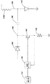
図8は、図5に示されるようにブレークダウン・パルス及びフォローオン・パルスを生成する電子回路の一例の一部分概略的な回路図を示す。図8において、ブレークダウン・パルス及び1つのフォローオン・パルスのみを発生する回路が、示されている。希望されるそれぞれの追加のフォローオン・パルスに関しては、破線で囲まれた回路110を複製することができ、そして全てのそのような回路は、それらのブースト・トランスフォーマ102の2次巻線と直列に接続されることができ、それによりそれぞれのそのような回路は、シーケンス化されたパルスの1つをイグナイタに順に供給する。(並列構成も可能であることに注目されたい。)
ブレークダウン放電を与える高電圧は、SCR104Aのスイッチングを起こすため104で印加された信号によりトリガされる高エネルギ点火コイル100により発生される。高エネルギ点火コイル100は、米国テキサス州エルパソ所在のオートトロニクス・コントロールズ・コーポレーション(Autotronics Controls Corporation)によるd/b/a MSD Ignitionにより市販されているコイル・モデル8261のようなしかしこれに限定さされるものではないいずれの適切な点火コイルであってよい。通常産業界では「点火コイル」と呼ばれているが、構成要素100は、実際には、トランスフォーマである。前述のモデル8261点火コイルは、低いインダクタンスの1次コイルを有し、そして1次コイルが付勢されるときその2次コイルから42−43kVの出力を与える。トランスフォーマ100の2次コイルは、(ブースト・トランスフォーマ102の2次コイル102Bを介して)イグナイタ101の1又はそれより多い電極に直接接続され、そのイグナイタ101の別の電極は、接地される。
FIG. 8 shows a partial schematic circuit diagram of an example of an electronic circuit that generates breakdown and follow-on pulses as shown in FIG. In FIG. 8, a circuit that generates only a breakdown pulse and one follow-on pulse is shown. For each additional follow-on pulse desired, the
The high voltage that provides the breakdown discharge is generated by a high
ダイオードのストリング106(ダイオードのそれぞれは高抵抗が並列接続されている。)は、点火コイル100の出力電圧を単一の極性に制限し、リンギングを防止する。
ブレークダウン・パルス後に、トリガ信号が、105に印加されて、フォローオン・パルスを発生させる。ブースト・トランスフォーマ102は、キャパシタ103を放電することにより誘発される電流のパルスをイグナイタ101への高電圧ライン(HVL)に供給する。キャパシタ103は、例えば、約500Vのような比較的低い電圧に充電され、次いでブースト・トランスフォーマ102の1次コイル102Aを介し更にSCR105Aを介して接地へ放電される。
A string of diodes 106 (each of the diodes is connected in high resistance in parallel) limits the output voltage of the
After the breakdown pulse, a trigger signal is applied to 105 to generate a follow-on pulse. The
トリガ信号は、固定の又はプログラマブルなパラメータを備えるいずれの適切な回路により発生されることができる。
高電圧ラインに接続されたイグナイタ電極はまた、ダイオードのストリング107、及びRC回路網111を介して、示された500V電源のような低電圧電源に接続される。RC回路網111の抵抗値は、シマー電流isを供給するよう設定される。
The trigger signal can be generated by any suitable circuit with fixed or programmable parameters.
The igniter electrode connected to the high voltage line is also connected via
図8の点火回路は、ブレークダウン電圧を発生し、初期電流、及び希望される電流のフォローオン・パルスを供給する単なる1つの方法を表すことが認められるであろう。匹敵するパルス化を生じるいずれの他の適切なメカニズムを採用し得る。例えば、正弦波電流パルスのような発振電流パルスを与えることができるであろう共振電流回路を、サブ回路のそれぞれが単一のパルスを発生する示された複数のサブ回路の代わりに、用いることができるであろう。更に、電圧及びダイオードの極性の適切な反転により、図8の回路は、正のパルスの代わりに負のパルスを発生するため用いることができるであろう。 It will be appreciated that the ignition circuit of FIG. 8 represents just one way of generating a breakdown voltage and providing an initial current and a follow-on pulse of the desired current. Any other suitable mechanism that produces comparable pulsing may be employed. For example, using a resonant current circuit that could provide an oscillating current pulse, such as a sinusoidal current pulse, instead of the multiple subcircuits shown, each of the subcircuits generating a single pulse Will be able to. Furthermore, with the proper reversal of voltage and diode polarity, the circuit of FIG. 8 could be used to generate a negative pulse instead of a positive pulse.
点火回路アーキテクチャの別の例(単純化した形式で)が、図9に参照番号130で示されている。基本的な回路構成要素のみが示されており、実際の実現は、他の従来通りの構成要素を必要とすることが理解されるであろう。電源132は、電圧(単に、それを区別する目的のため「高」電圧と名付ける。)を供給する。当該電圧は、それがトランスフォーマ134により昇圧されたとき、プラズマをイグナイタ(図示せず)で生成するのに十分なブレークダウン電圧を発生することができる程十分に高い。電源132は、ダイオード136を介して1次巻線134Aの第1の端部に接続されて、1次巻線134Aの他方の端部と接地との間に接続されたキャパシタ138を充電する。パルス発生器142は、パルスのトレイン又はシーケンスを供給する。第1のパルス上で、パルス発生器142からの出力信号は、電子的に制御されるスイッチ144を閉成する。この動作は、ダイオード136のアノードを接地し、電源132との接続を実効的に切り、それによりそれが短絡されないで、そしてキャパシタ138が1次巻線134Aを介して放電される。トランスフォーマ134は、可飽和コアの昇圧トランスフォーマである。HV電源132は、典型的には、数百ボルトの出力電圧を有する。スイッチ144の閉成は、大きい電圧スイングをトランスフォーマ134の1次巻線134Aの両端に発生する。典型的には、約1:35−1:40の巻線比が、トランスフォーマ134に用いられ、そしてこれは、1次巻線134A上の5〜6百ボルトを2次巻線134Bの両端の数万ボルトの範囲まで昇圧するであろう。この後者の電圧は、(2次巻線134Bの一方の端部に接続された(図示せず))イグナイタに印加されたときブレークダウンを起こすのに十分である。
Another example (in simplified form) of the ignition circuit architecture is shown in FIG. It will be appreciated that only basic circuit components are shown, and that an actual implementation requires other conventional components. The power supply 132 supplies a voltage (simply named “high” voltage for the purpose of distinguishing it). The voltage is high enough that when it is boosted by the
前述のパルスはまた、トランスフォーマ134のコアを飽和させることが好ましい。
コアの飽和に起因して、その飽和が全く衰退する前に、次のパルスがパルス発生器142により供給される場合、そのようなパルスは、ブレークダウン・レベル出力電圧を出力ライン152上に発生しないであろう。
The aforementioned pulses also preferably saturate the core of the
Due to core saturation, if the next pulse is supplied by
2次巻線134Bの他方の端(154で示す。)、及びキャパシタ156の一端は、ダイオード158を介して接地される。キャパシタ156は、「低電圧」(LV)電源162により保護ダイオード164を介して充電される。パルス発生器142からのパルスが電子スイッチ166により受け取られたとき、ノード168は、接地され、そしてキャパシタ156は、直列接続されたダイオード172、抵抗174及びスイッチ168を介して接地される。
The other end (indicated by 154) of the secondary winding 134B and one end of the
「低電圧」(LV)電源162は、典型的には、0−1000ボルトの範囲の電圧を供給する。キャパシタ156は、典型的な点火システムでは大きいキャパシタンスであり、そして抵抗174は、放電電流(これはトランスフォーマ134の2次巻線134Bを介して引かれる。)を約50アンペア(より低い電流がフォローオン・パルスに十分である場合にはそれより小さく)までに制限する大きさにされ得る。
A “low voltage” (LV)
ダイオード182及び184は、単に、それらのそれぞれのスイッチを、それらを破壊することができるであろう逆極性スパイクから保護する。
電源132及び162は、別々に示されているが、単一の電源を一部の応用では用いてもよい。また、用語「低電圧」及び「高電圧」は、電源132の出力が電源162の出力より高い電圧であることが最も典型的であるにも拘わらず、そうであることを要求することを意図しているものではない。
Although
ダイオード164が、その関連の電源が関連のスイッチが閉成されるとき短絡された出力を有することから保護するというダイオード136と同じ理由のため含められている。
また、電源132、162の正確な構成に応じて、適用可能な場合、これらの電源の一方又は両方と対応するスイッチ144又は166との間に直列接続状態で抵抗を配置して、電源の出力電流及び対応のキャパシタの充電時間を制限することが望ましい。
A
Depending on the exact configuration of the power supplies 132, 162, if applicable, a resistor may be placed in series connection between one or both of these power supplies and the
スイッチ144、146は、SCR、IGBT(特にスイッチ144にとって)、MCT、及び今又は将来存在し得る他の高電圧スイッチング素子のような様々な半導体を用いて実現され得る。
The
小さいキャパシタ159は、ダイオード158をバイパスし、迅速な電圧変化のため接地への低インピーダンス経路を与えて、ダイオード158を大きい逆スパイクに対して保護する。
A
他の変形が可能である。例えば、スイッチ144及び146を作動させる単一のパルス発生器の代わりに、各スイッチが異なるパルス発生器により作動されてもよく、又はスイッチを駆動する異なる出力又は異なった状態の出力信号(これは多分コモン信号から導出される。)を有する1つのパルス発生器を用いてもよい。又は、図10においてスイッチング素子(例えば、MCT)186で示されるように1つのスイッチを2つのスイッチの代わりに用いてもよい。(図10において、抵抗Rは、必要でないかも知れないが、電源の詳細に応じて特に示されている。)異なるパルス発生器がそれぞれのスイッチを駆動する場合、それらは、独立に制御されることができ、そしてこれは、様々な動作モードに適応することを可能にするであろう。
Other variations are possible. For example, instead of a single pulse generator that activates
図9において、抵抗174は、それがオプションであることを示すため破線のボックスの中に示されている。電源162がフォローオン電流パルスの所望の振幅を制御するためキャパシタ156と関係して設定されることに拘わらず、キャパシタ156に蓄積されたエネルギの全てがアークへ移行されることができるわけではない。フォローオン・パルスの中の電流を各パルスの間隔にわたり維持するため、キャパシタ156は、制御されたレート(割合)で放電されねばならない。これを行う1つの方法は、抵抗174のような抵抗を介してキャパシタ156を放電する方法である。不都合にも、抵抗174の使用は、大量の蓄積されたエネルギを熱として放散することをもたらす。実際、より多くのエネルギは、プラズマの移動で費やされるより抵抗174で熱として失われる。従って、この回路は、エネルギの不効率な使用を来している。
In FIG. 9,
スイッチ素子166を制御された電流排出経路にすることにより回路の効率を改善し且つ熱放散を低減することが可能である。従って、キャパシタ156の電流排出を制限するため抵抗174を用いる代わりに、スイッチ・トランジスタ(又は類似の構成要素)がその要求を引き受け、制御された放電を与える。より詳細には、図11に示されるように、能動型スイッチング素子(その図では、MOSFET166′として示される。)が、ノード168から抵抗192を介して接地に接続される。その抵抗192にかかる電圧は、トランジスタ166′を通る実際の電流を測定するための代理として感知される。パルス発生器142とトランジスタ166′のゲートとの間に介挿されたゲート駆動ロジック194は、抵抗192の電圧に応答して、トランジスタ166′を、可変のデューティ・サイクルと、抵抗174の使用から生じる電力放散の低減とを有するスイッチング・レギュレータとして動作させる。ゲート駆動ロジック194は、様々な方法で実現され、固定のロジックを含んでもよく、又はそれは、おそらく当該ロジックを動作させるためのマイクロコントローラを含むプログラマブル・ロジックを含んでもよい。マイクロコントローラを用いる利点は、上記ロジックが本明細書で説明した様々なモード、例えば、シマー電流の有り又は無しで実行するために回路を動作させるよう構成されることができる点にある。
By making the switch element 166 a controlled current drain path, it is possible to improve circuit efficiency and reduce heat dissipation. Thus, instead of using
正極性のパルスの発生が点火回路の説明された例から結果として生じるにも拘わらず、エレクトロニクスの当業者は、同じことを有することが希望されるならば、それらから、負極性のパルス、又は極性が変わるパルスすらを生成するであろう点火回路を容易に導出することができるであろう。また、一部又は全てのトリガ・パルスが出力パルスと異なる極性であることが望ましい場合がある。 If the generation of a positive pulse results from the illustrated example of an ignition circuit, those skilled in the art of electronics, if desired to have the same, from it, It would be easy to derive an ignition circuit that would generate even pulses of varying polarity. It may also be desirable for some or all of the trigger pulses to have a different polarity than the output pulse.
ゲート駆動ロジックの詳細な設計及びブレークダウン電圧、フォローオン・パルス、イグナイタ等に関するパラメータは、点火システムが適合することを要求される特定のエンジン仕様に依存するだろう。それらの要件、及びコスト、部品の可用性等々のような考慮は、同様に構成要素の選択に影響を及ぼすであろう。これらのパラメータの一部の決定は、そのために点火システム又は回路が意図されるエンジンのモデルについての或る程度の実験法を要求し得る。 The detailed design of the gate drive logic and parameters related to breakdown voltage, follow-on pulse, igniter, etc. will depend on the specific engine specification that the ignition system is required to meet. Those requirements, and considerations such as cost, component availability, etc. will similarly affect the selection of components. The determination of some of these parameters may require some degree of experimentation on the model of the engine for which the ignition system or circuit is intended.
問題及びそれらの解法が、唯1つの形式のTSIを用いて説明されたが、これら問題及びそれらの解法の両方が、並列及び同軸の両方の電極を用いて、他のTSI設計に等しく適用される。 Although the problems and their solutions have been described using only one type of TSI, both these problems and their solutions apply equally to other TSI designs using both parallel and coaxial electrodes. The
或る一定の方法及び装置が高い圧力及び非常に高い圧力で動作する内燃機関との使用に関して説明されたが、この技術はまた、より低い従来の圧力で、又は従来のスパイク・プラグと共にすら動作する内燃機関の走行スパーク・イグナイタと使用することができることが理解されるであろう。しかしながら、利点は、多分走行スパーク・イグナイタの場合最大であろう。 Although certain methods and devices have been described for use with internal combustion engines that operate at high and very high pressures, this technique also operates at lower conventional pressures or even with conventional spike plugs. It will be appreciated that it can be used with a traveling spark igniter of an internal combustion engine. However, the advantage is probably greatest in the case of a traveling spark igniter.
また、動作理論が提示されたが、この理論を非常に多く制限するかも知れない多数の単純化した仮定が存在する。それにもかかわらず、特許請求の範囲に記載された発明は、シミュレートされた高圧エンジン環境で実用に役立つ点火システムをもたらし、そして解析におけるいずれの単純化及びエラーが、本発明の価値を減じないことが理解されるであろう。 Also, although a theory of operation has been presented, there are a number of simplified assumptions that may limit this theory very much. Nevertheless, the claimed invention results in an ignition system that is useful in a simulated high pressure engine environment, and any simplifications and errors in the analysis do not detract from the value of the present invention. It will be understood.
この発明の少なくとも1つの実施形態の幾つかの局面が説明されたが、様々な代替、変更及び改善が、当業者により容易に行われることが認められるべきである。そのような代替、変更及び改善は、この開示の一部であることを意図しており、そして本発明の趣旨及び範囲内にあることを意図するものである。従って、前述の説明及び図面は、単なる例示である。 While several aspects of at least one embodiment of the present invention have been described, it should be appreciated that various alternatives, modifications and improvements can be readily made by those skilled in the art. Such alterations, modifications, and improvements are intended to be part of this disclosure, and are intended to be within the spirit and scope of the invention. Accordingly, the foregoing description and drawings are merely exemplary.
Claims (29)
b.ブレークダウンに続いて、2つ以上の比較的低電圧のフォローオン・パルスのシーケンスを前記電極に印加するステップと、
c.前記フォローオン・パルスのシーケンスにおける少なくとも1つのフォローオン・パルス以前の前記プラズマ・カーネルの全体の再結合を阻止するステップと、
を備え、
それにより、前記プラズマ・カーネルが、前記フォローオン・パルスのシーケンスにより前記電極の自由端に向けて移動することを強制される、プラズマ発生方法。 a. Applying a high voltage to the igniter, wherein the high voltage causes a breakdown between the electrodes to cause a high current discharge in a starting region within the igniter and formation of a plasma kernel adjacent to the starting region. Said applying step being of sufficient amplitude to provide;
b. Subsequent to breakdown, applying a sequence of two or more relatively low voltage follow-on pulses to the electrodes;
c. Preventing total recombination of the plasma kernel before at least one follow-on pulse in the sequence of follow-on pulses;
With
A plasma generation method whereby the plasma kernel is forced to move towards the free end of the electrode by the sequence of follow-on pulses.
b.ブレークダウンに続いて、電流アークの前記電極への拡散付加を維持するよう十分に低い電流の2つ以上の比較的低電圧のフォローオン・パルスのシーケンスを前記電極に印加するステップと、
c.前記フォローオン・パルスのシーケンスにおける少なくとも1つのフォローオン・パルス以前の前記プラズマ・カーネルの全体の再結合を阻止するステップと、
を備え、
それにより、前記プラズマ・カーネルが、前記フォローオン・パルスのシーケンスの影響下で前記電極の自由端に向けて移動することを強制され且つ移動することが可能である、プラズマ発生方法。 a. Applying a high voltage to the igniter, wherein the high voltage causes a breakdown between the electrodes to cause a high current discharge in a starting region within the igniter and formation of a plasma kernel adjacent to the starting region. Said applying step being of sufficient amplitude to provide;
b. Subsequent to breakdown, applying a sequence of two or more relatively low voltage follow-on pulses at a sufficiently low current to maintain diffusion addition of a current arc to the electrode;
c. Preventing total recombination of the plasma kernel before at least one follow-on pulse in the sequence of follow-on pulses;
With
Thereby, the plasma generation method, wherein the plasma kernel is forced and can be moved towards the free end of the electrode under the influence of the sequence of follow-on pulses.
b.ブレークダウンに続いて、2つ以上の比較的低電圧のフォローオン・パルスのシーケンスを前記電極に印加するステップと、
前記フォローオン・パルスのシーケンスにおける少なくとも1つのフォローオン・パルス以前の前記プラズマ・カーネルの全体の再結合を阻止するステップと、
を備え、
それにより、前記プラズマ・カーネルが、前記フォローオン・パルスのシーケンスにより前記電極の自由端に向けて移動することを強制される、燃料点火方法。 a. Applying a high voltage to an igniter in the presence of combustible fuel, the high voltage causing a breakdown between the electrodes of the igniter, a high current discharge in a starting region within the igniter, and the starting Said applying step having an amplitude sufficient to effect the formation of a plasma kernel adjacent to the region;
b. Subsequent to breakdown, applying a sequence of two or more relatively low voltage follow-on pulses to the electrodes;
Preventing total recombination of the plasma kernel before at least one follow-on pulse in the sequence of follow-on pulses;
With
A fuel ignition method whereby the plasma kernel is forced to move towards the free end of the electrode by the sequence of follow-on pulses.
a.前記イグナイタが内燃機関の燃料−空気混合気の中に配設されるとき、電気的ブレークダウン放電を起こすことが可能である高電圧を高電流で前記イグナイタの電極間の開始領域に与えることにより、プラズマ・カーネルを前記開始領域に前記放電により形成する手段と、
b.比較的低電圧及び低電流のフォローオン・パルスにより前記プラズマ・カーネルを前記電極の自由端に向けて移動することを強制するのに十分な電圧及び電流振幅及びタイミングを有する2つ以上の前記比較的低電圧及び低電流のフォローオン・パルスのシーケンスを与える手段と、
c.前記ブレークダウン放電と前記フォローオン・パルスのシーケンスにおける第1のフォローオン・パルスとの間の間隔において、前記間隔における前記プラズマ・カーネルの全体の再結合を阻止するのに十分なシマー電流を前記イグナイタに与える手段と、
を備える点火回路。 An ignition circuit for supplying power to an igniter of an internal combustion engine,
a. When the igniter is disposed in a fuel-air mixture of an internal combustion engine, a high voltage capable of causing an electrical breakdown discharge is applied at a high current to a starting region between the igniter electrodes. Means for forming a plasma kernel in the starting region by the discharge;
b. Two or more of the comparisons having sufficient voltage and current amplitude and timing to force the plasma kernel to move toward the free end of the electrode by a relatively low voltage and low current follow-on pulse. Means for providing a sequence of static low voltage and low current follow-on pulses;
c. In the interval between the breakdown discharge and the first follow-on pulse in the follow-on pulse sequence, a simmer current sufficient to prevent total recombination of the plasma kernel in the interval Means to give the igniter,
Ignition circuit comprising.
前記2次巻線が、前記イグナイタの1つの電極に接続するためのリードを有し、
電気的ブレークダウン放電を起こすことが可能である高電圧を与える前記手段が更に、信号を前記1次巻線にトリガして、高電圧パルスを前記2次巻線に誘発する回路を含む
請求項20に記載の点火回路。 Said means for providing a high voltage capable of causing an electrical breakdown discharge comprises a high voltage low inductance ignition coil having a primary winding and a secondary winding;
The secondary winding has leads for connecting to one electrode of the igniter;
The means for providing a high voltage capable of causing an electrical breakdown discharge further comprises circuitry for triggering a signal on the primary winding to induce a high voltage pulse on the secondary winding. 21. The ignition circuit according to 20.
比較的低い電圧源と、
前記フォローオン・パルスのそれぞれに対して、前記比較的低い電圧源により充電されるキャパシタと、
前記リードに接続された前記2次巻線と、前記1次巻線とを有するパルス・トランスフォーマとを備え、
前記パルス・トランスフォーマの前記1次巻線を介して、前記キャパシタが、トリガ信号に応答して放電されて、前記フォローオン・パルスを前記リードに誘発する
請求項22に記載の点火回路。 Said means for providing a sequence of relatively low voltage follow-on pulses;
A relatively low voltage source,
A capacitor charged by the relatively low voltage source for each of the follow-on pulses;
A pulse transformer having the secondary winding connected to the lead and the primary winding;
23. The ignition circuit of claim 22, wherein the capacitor is discharged in response to a trigger signal through the primary winding of the pulse transformer to induce the follow-on pulse to the lead.
前記可飽和コア上に、前記1次巻線及び前記2次巻線が、形成され、
前記可飽和コアは、前記電気的ブレークダウンが生じたとき実質的に飽和し、それにより前記2次巻線が、その後に、実質的に低減されたインダクタンスを有する
請求項20に記載の点火回路。 The ignition coil includes a saturable core;
The primary winding and the secondary winding are formed on the saturable core,
21. The ignition circuit of claim 20, wherein the saturable core is substantially saturated when the electrical breakdown occurs, whereby the secondary winding subsequently has a substantially reduced inductance. .
a.パルスをイグナイタへの接続のための出力に発生する高電圧パルス発生器であって、前記パルスの最大電圧は、前記イグナイタに供給されたときブレークダウン放電を起こすことが可能であり、且つそれに続く高電流を、前記イグナイタが燃焼−空気混合気の中に配設されるとき前記イグナイタの電極間の開始領域に生じさせることが可能であり、それによりプラズマ・カーネルを前記放電により前記表面に隣接して形成する、前記高電圧パルス発生器と、
b.比較的低電圧及び低電流のフォローオン・パルスにより前記プラズマ・カーネルを前記電極の自由端に向けて移動することを強制するのに十分な電圧及び電流振幅及びタイミングを有する2つ以上の前記比較的低電圧及び低電流のフォローオン・パルスのシーケンスを前記出力に発生する低電圧パルス発生器と、
c.前記ブレークダウン放電と前記フォローオン・パルスのシーケンスにおける第1のフォローオン・パルスとの間の間隔において、前記間隔における前記プラズマ・カーネルの全体の再結合を阻止するのに十分なシマー電流を前記の出力ラインに供給するシマー電流源と、
を備える点火回路。 An ignition circuit for supplying power to an igniter of an internal combustion engine,
a. A high voltage pulse generator that generates a pulse at the output for connection to an igniter, the maximum voltage of the pulse being capable of causing a breakdown discharge when applied to the igniter and subsequent High currents can be generated in the starting region between the igniter electrodes when the igniter is disposed in a combustion-air mixture, thereby causing a plasma kernel to be adjacent to the surface by the discharge. And forming the high voltage pulse generator,
b. Two or more of the comparisons having sufficient voltage and current amplitude and timing to force the plasma kernel to move toward the free end of the electrode by a relatively low voltage and low current follow-on pulse. A low voltage pulse generator for generating a sequence of static low voltage and low current follow-on pulses at the output;
c. In the interval between the breakdown discharge and the first follow-on pulse in the follow-on pulse sequence, a simmer current sufficient to prevent total recombination of the plasma kernel in the interval A simmer current source for the output line of
Ignition circuit comprising.
Applications Claiming Priority (3)
| Application Number | Priority Date | Filing Date | Title |
|---|---|---|---|
| US67289205P | 2005-04-19 | 2005-04-19 | |
| US60/672,892 | 2005-04-19 | ||
| PCT/US2006/014840 WO2006113850A1 (en) | 2005-04-19 | 2006-04-19 | Method and apparatus for operating traveling spark igniter at high pressure |
Publications (3)
| Publication Number | Publication Date |
|---|---|
| JP2008537061A JP2008537061A (en) | 2008-09-11 |
| JP2008537061A5 JP2008537061A5 (en) | 2010-12-02 |
| JP5377958B2 true JP5377958B2 (en) | 2013-12-25 |
Family
ID=36747126
Family Applications (1)
| Application Number | Title | Priority Date | Filing Date |
|---|---|---|---|
| JP2008507856A Active JP5377958B2 (en) | 2005-04-19 | 2006-04-19 | Method and apparatus for operating a traveling spark igniter at high pressure |
Country Status (7)
| Country | Link |
|---|---|
| US (12) | US7467612B2 (en) |
| EP (3) | EP2426796B1 (en) |
| JP (1) | JP5377958B2 (en) |
| KR (1) | KR101250046B1 (en) |
| CN (1) | CN101218722B (en) |
| AT (1) | ATE535972T1 (en) |
| WO (1) | WO2006113850A1 (en) |
Families Citing this family (40)
| Publication number | Priority date | Publication date | Assignee | Title |
|---|---|---|---|---|
| WO2006113850A1 (en) * | 2005-04-19 | 2006-10-26 | Knite, Inc. | Method and apparatus for operating traveling spark igniter at high pressure |
| JP4967835B2 (en) * | 2006-12-20 | 2012-07-04 | 株式会社デンソー | Plasma ignition device |
| FR2913297B1 (en) * | 2007-03-01 | 2014-06-20 | Renault Sas | OPTIMIZING THE GENERATION OF A RADIO FREQUENCY IGNITION SPARK |
| US8499746B2 (en) | 2007-07-12 | 2013-08-06 | Imagineering, Inc. | Internal combustion engine using electromagnetic wave radiation to activate burnt gas |
| JP2009036123A (en) * | 2007-08-02 | 2009-02-19 | Nissan Motor Co Ltd | Non-equilibrium plasma discharge engine |
| US8887683B2 (en) * | 2008-01-31 | 2014-11-18 | Plasma Igniter LLC | Compact electromagnetic plasma ignition device |
| US8783220B2 (en) | 2008-01-31 | 2014-07-22 | West Virginia University | Quarter wave coaxial cavity igniter for combustion engines |
| JP4952641B2 (en) * | 2008-04-14 | 2012-06-13 | 株式会社デンソー | Ignition system for internal combustion engine |
| JP2011034953A (en) * | 2009-02-26 | 2011-02-17 | Ngk Insulators Ltd | Plasma igniter, and ignition device of internal combustion engine |
| JP5425575B2 (en) * | 2009-09-18 | 2014-02-26 | ダイハツ工業株式会社 | Method for determining the combustion state of a spark ignition internal combustion engine |
| DE102010015344B4 (en) * | 2010-04-17 | 2013-07-25 | Borgwarner Beru Systems Gmbh | A method for igniting a fuel-air mixture of a combustion chamber, in particular in an internal combustion engine by generating a corona discharge |
| US8760067B2 (en) * | 2011-04-04 | 2014-06-24 | Federal-Mogul Ignition Company | System and method for controlling arc formation in a corona discharge ignition system |
| US20140232256A1 (en) | 2011-07-26 | 2014-08-21 | Knite, Inc. | Traveling spark igniter |
| US20130308245A1 (en) * | 2012-05-18 | 2013-11-21 | Honeywell International Inc. | Inductive start and capacitive sustain ignition exciter system |
| AU2013352295B2 (en) | 2012-11-29 | 2017-10-05 | Advanced Fuel And Ignition System Inc. | Multi-spark and continuous spark ignition module |
| US9617965B2 (en) * | 2013-12-16 | 2017-04-11 | Transient Plasma Systems, Inc. | Repetitive ignition system for enhanced combustion |
| SG11201608465YA (en) | 2014-04-08 | 2016-11-29 | Plasma Igniter Inc | Dual signal coaxial cavity resonator plasma generation |
| US9828967B2 (en) * | 2015-06-05 | 2017-11-28 | Ming Zheng | System and method for elastic breakdown ignition via multipole high frequency discharge |
| CN105221319A (en) * | 2015-08-31 | 2016-01-06 | 中国科学院电工研究所 | A kind of for lighting a fire and the sliding discharge reactor of auxiliary combustion |
| US10590887B2 (en) | 2016-05-20 | 2020-03-17 | Alphaport, Inc. | Spark exciter operational unit |
| US10837369B2 (en) | 2017-08-23 | 2020-11-17 | General Electric Company | Igniter assembly for a gas turbine combustor |
| WO2020112108A1 (en) | 2017-11-29 | 2020-06-04 | COMET Technologies USA, Inc. | Retuning for impedance matching network control |
| US20190186369A1 (en) | 2017-12-20 | 2019-06-20 | Plasma Igniter, LLC | Jet Engine with Plasma-assisted Combustion |
| US10995672B2 (en) | 2018-07-12 | 2021-05-04 | General Electric Company | Electrical waveform for gas turbine igniter |
| US10859058B1 (en) | 2019-01-31 | 2020-12-08 | Tom Rothenbuhler | Direct fuel injected spark igniter for internal combustion engines |
| US11114279B2 (en) | 2019-06-28 | 2021-09-07 | COMET Technologies USA, Inc. | Arc suppression device for plasma processing equipment |
| US11527385B2 (en) | 2021-04-29 | 2022-12-13 | COMET Technologies USA, Inc. | Systems and methods for calibrating capacitors of matching networks |
| US11596309B2 (en) | 2019-07-09 | 2023-03-07 | COMET Technologies USA, Inc. | Hybrid matching network topology |
| US11107661B2 (en) | 2019-07-09 | 2021-08-31 | COMET Technologies USA, Inc. | Hybrid matching network topology |
| US11830708B2 (en) | 2020-01-10 | 2023-11-28 | COMET Technologies USA, Inc. | Inductive broad-band sensors for electromagnetic waves |
| US11887820B2 (en) | 2020-01-10 | 2024-01-30 | COMET Technologies USA, Inc. | Sector shunts for plasma-based wafer processing systems |
| US11670488B2 (en) | 2020-01-10 | 2023-06-06 | COMET Technologies USA, Inc. | Fast arc detecting match network |
| US11521832B2 (en) | 2020-01-10 | 2022-12-06 | COMET Technologies USA, Inc. | Uniformity control for radio frequency plasma processing systems |
| US11605527B2 (en) | 2020-01-20 | 2023-03-14 | COMET Technologies USA, Inc. | Pulsing control match network |
| US11961711B2 (en) | 2020-01-20 | 2024-04-16 | COMET Technologies USA, Inc. | Radio frequency match network and generator |
| US11373844B2 (en) | 2020-09-28 | 2022-06-28 | COMET Technologies USA, Inc. | Systems and methods for repetitive tuning of matching networks |
| US11923175B2 (en) | 2021-07-28 | 2024-03-05 | COMET Technologies USA, Inc. | Systems and methods for variable gain tuning of matching networks |
| CN114109692B (en) * | 2021-11-26 | 2022-09-27 | 山东大学 | Fast pulse multipoint discharge system and engine combustion control method |
| CN114234940B (en) * | 2021-12-16 | 2023-08-15 | 国网四川省电力公司电力科学研究院 | Measurement system and method for tree line discharge basic data of high-voltage power line |
| US11657980B1 (en) | 2022-05-09 | 2023-05-23 | COMET Technologies USA, Inc. | Dielectric fluid variable capacitor |
Family Cites Families (80)
| Publication number | Priority date | Publication date | Assignee | Title |
|---|---|---|---|---|
| US3413518A (en) | 1967-01-31 | 1968-11-26 | Ass Elect Ind | Sliding spark ignition system with an inductance and capacitor in series with a three electrode spark plug |
| US3567987A (en) | 1968-06-06 | 1971-03-02 | Gerald L Schnurmacher | Spark plug construction |
| GB1410471A (en) | 1971-11-16 | 1975-10-15 | Ass Eng Ltd | Ignition devices |
| US3788293A (en) * | 1972-11-10 | 1974-01-29 | Mcculloch Corp | Low impedance capacitor discharge system and method |
| US3908146A (en) * | 1972-12-11 | 1975-09-23 | Lacrex Brevetti Sa | Break ignition plug and ignition device |
| JPS5142245B2 (en) | 1974-07-08 | 1976-11-15 | ||
| DE2533046C3 (en) * | 1975-07-24 | 1978-11-30 | Robert Bosch Gmbh, 7000 Stuttgart | Ignition device for internal combustion engines |
| US4122816A (en) | 1976-04-01 | 1978-10-31 | The United States Of America As Represented By The Administrator Of The National Aeronautics And Space Administration | Plasma igniter for internal combustion engine |
| US4369756A (en) | 1980-01-11 | 1983-01-25 | Nissan Motor Co., Ltd. | Plasma jet ignition system for internal combustion engine |
| JPS60551B2 (en) | 1980-02-29 | 1985-01-08 | 日産自動車株式会社 | plasma igniter |
| JPS5732069A (en) | 1980-07-31 | 1982-02-20 | Nissan Motor Co Ltd | Igniter for internal combustion engine |
| JPS5756668A (en) | 1980-09-18 | 1982-04-05 | Nissan Motor Co Ltd | Plasma igniter |
| JPS5756667A (en) | 1980-09-18 | 1982-04-05 | Nissan Motor Co Ltd | Plasma igniter |
| JPS57140567A (en) * | 1981-02-23 | 1982-08-31 | Nissan Motor Co Ltd | Plasma ignition device for internal combustion engine |
| JPS57165673A (en) | 1981-04-07 | 1982-10-12 | Nissan Motor Co Ltd | Plasma ignition device |
| JPS57203867A (en) | 1981-06-09 | 1982-12-14 | Nissan Motor Co Ltd | Plasma ignition apparatus |
| JPS57198372U (en) * | 1981-06-12 | 1982-12-16 | ||
| JPS57206776A (en) | 1981-06-16 | 1982-12-18 | Nissan Motor Co Ltd | Plasma ignition device |
| JPS58162718A (en) | 1982-03-23 | 1983-09-27 | Nissan Motor Co Ltd | Ignition plug for starting diesel engine |
| US4493297A (en) | 1982-09-27 | 1985-01-15 | Geo-Centers, Inc. | Plasma jet ignition device |
| US4487192A (en) * | 1983-04-18 | 1984-12-11 | Ford Motor Co | Plasma jet ignition system |
| US4760820A (en) | 1983-07-20 | 1988-08-02 | Luigi Tozzi | Plasma jet ignition apparatus |
| US4471732A (en) | 1983-07-20 | 1984-09-18 | Luigi Tozzi | Plasma jet ignition apparatus |
| US4766855A (en) | 1983-07-20 | 1988-08-30 | Cummins Engine Co., Inc. | Plasma jet ignition apparatus |
| US4677960A (en) | 1984-12-31 | 1987-07-07 | Combustion Electromagnetics, Inc. | High efficiency voltage doubling ignition coil for CD system producing pulsed plasma type ignition |
| US4774914A (en) | 1985-09-24 | 1988-10-04 | Combustion Electromagnetics, Inc. | Electromagnetic ignition--an ignition system producing a large size and intense capacitive and inductive spark with an intense electromagnetic field feeding the spark |
| GB8529223D0 (en) | 1985-11-27 | 1986-01-02 | Lucas Ind Plc | Monitoring gas turbine engine |
| DE3544176C1 (en) | 1985-12-13 | 1987-05-21 | Beru Werk Ruprecht Gmbh Co A | Spark plug with combined sliding and air spark gaps |
| US4841925A (en) * | 1986-12-22 | 1989-06-27 | Combustion Electromagnetics, Inc. | Enhanced flame ignition for hydrocarbon fuels |
| AU1088188A (en) | 1986-12-22 | 1988-07-15 | Combustion Electromagnetics Inc. | Formation of electric field discharges |
| US4893605A (en) * | 1987-06-25 | 1990-01-16 | Mitsubishi Denki Kabushiki Kaisha | Ignition device for internal combustion engine |
| US5007389A (en) | 1987-12-17 | 1991-04-16 | Ryohei Kashiwara | Ignition plug for internal combustion engines and a process for igniting gas mixture by the use thereof |
| US4805570A (en) | 1987-12-23 | 1989-02-21 | Brunswick Corporation | Multipoint spark ignition system |
| US4846129A (en) | 1988-02-09 | 1989-07-11 | Chrysler Motors Corporation | Ignition system improvements for internal combustion engines |
| US4930473A (en) | 1988-12-09 | 1990-06-05 | Texas Ignitors Company, Inc. | Swirl chamber and spark plug assembly |
| US4996967A (en) | 1989-11-21 | 1991-03-05 | Cummins Engine Company, Inc. | Apparatus and method for generating a highly conductive channel for the flow of plasma current |
| US5211142A (en) | 1990-03-30 | 1993-05-18 | Board Of Regents, The University Of Texas System | Miniature railgun engine ignitor |
| US5076223A (en) | 1990-03-30 | 1991-12-31 | Board Of Regents, The University Of Texas System | Miniature railgun engine ignitor |
| US5228425A (en) | 1991-01-04 | 1993-07-20 | Sylvan Simons | Ignition system for internal combustion engine |
| US5131376A (en) | 1991-04-12 | 1992-07-21 | Combustion Electronics, Inc. | Distributorless capacitive discharge ignition system |
| US5187404A (en) | 1991-08-05 | 1993-02-16 | Cooper Industries, Inc. | Surface gap igniter |
| US5197448A (en) | 1991-08-23 | 1993-03-30 | Massachusetts Institute Of Technology | Dual energy ignition system |
| US5207208A (en) | 1991-09-06 | 1993-05-04 | Combustion Electromagnetics Inc. | Integrated converter high power CD ignition |
| US5429103A (en) * | 1991-09-18 | 1995-07-04 | Enox Technologies, Inc. | High performance ignition system |
| KR950002633B1 (en) | 1991-10-15 | 1995-03-23 | 미쯔비시 덴끼 가부시기가이샤 | Ignition apparatus for internal combustion engine |
| GB9124824D0 (en) | 1991-11-22 | 1992-01-15 | Ortech Corp | Plasma-arc ignition system |
| US5456241A (en) | 1993-05-25 | 1995-10-10 | Combustion Electromagnetics, Inc. | Optimized high power high energy ignition system |
| US5377633A (en) | 1993-07-12 | 1995-01-03 | Siemens Automotive L.P. | Railplug direct injector/ignitor assembly |
| US5423306A (en) | 1993-10-22 | 1995-06-13 | Trigger, Deceased; Vernon A. | Internal plasma-combustion engine system |
| US5555862A (en) | 1994-07-19 | 1996-09-17 | Cummins Engine Company, Inc. | Spark plug including magnetic field producing means for generating a variable length arc |
| US5619959A (en) | 1994-07-19 | 1997-04-15 | Cummins Engine Company, Inc. | Spark plug including magnetic field producing means for generating a variable length arc |
| US5513605A (en) | 1994-08-22 | 1996-05-07 | Board Of Regents, The University Of Texas System | Cooled railplug |
| US5517961A (en) | 1995-02-27 | 1996-05-21 | Combustion Electromagnetics, Inc. | Engine with flow coupled spark discharge |
| US5754011A (en) | 1995-07-14 | 1998-05-19 | Unison Industries Limited Partnership | Method and apparatus for controllably generating sparks in an ignition system or the like |
| US5564403A (en) | 1995-10-16 | 1996-10-15 | Caterpillar Inc. | Spark ignition system and spark plug for ultra lean fuel/air mixtures |
| US5704321A (en) * | 1996-05-29 | 1998-01-06 | The Trustees Of Princeton University | Traveling spark ignition system |
| US6321733B1 (en) * | 1996-05-29 | 2001-11-27 | Knite, Inc. | Traveling spark ignition system and ignitor therefor |
| US6131555A (en) * | 1998-04-20 | 2000-10-17 | Cummins Engine Company, Inc. | System for controlling ignition energy of an internal combustion engine |
| AU5620000A (en) * | 1999-06-16 | 2001-01-02 | Knite, Inc. | Add on unit to conventional ignition systems to provide a follow-on current through a spark plug |
| ATE321206T1 (en) | 1999-09-15 | 2006-04-15 | Knite Inc | LONG LIFE, FORWARD-PROVING SPARK PLUG AND ASSOCIATED IGNITION CIRCUIT |
| TW505733B (en) * | 1999-09-15 | 2002-10-11 | Knite Inc | Electronic circuits for plasma generating devices |
| DE10031875A1 (en) | 2000-06-30 | 2002-01-10 | Bosch Gmbh Robert | Ignition method and corresponding ignition device |
| AT409406B (en) | 2000-10-16 | 2002-08-26 | Jenbacher Ag | IGNITION SYSTEM WITH AN IGNITION COIL |
| FR2817444B1 (en) * | 2000-11-27 | 2003-04-25 | Physiques Ecp Et Chimiques | GENERATORS AND ELECTRICAL CIRCUITS FOR SUPPLYING UNSTABLE HIGH VOLTAGE DISCHARGES |
| US6701904B2 (en) * | 2001-05-17 | 2004-03-09 | Altronic, Inc. | Capacitive discharge ignition system with extended duration spark |
| US6568362B2 (en) | 2001-06-12 | 2003-05-27 | Ut-Battelle, Llc | Rotating arc spark plug |
| NL1019448C2 (en) * | 2001-11-29 | 2003-06-03 | Simon Lucas Goede | Internal combustion engine and ignition circuit for an internal combustion engine. |
| US6670777B1 (en) * | 2002-06-28 | 2003-12-30 | Woodward Governor Company | Ignition system and method |
| JP4460940B2 (en) * | 2003-05-07 | 2010-05-12 | 株式会社ニューパワープラズマ | Induction plasma chamber with multiple discharge tube bridges |
| US7518085B1 (en) * | 2003-05-30 | 2009-04-14 | Alameda Applied Sciences Corp. | Vacuum arc plasma thrusters with inductive energy storage driver |
| US7066161B2 (en) * | 2003-07-23 | 2006-06-27 | Advanced Engine Management, Inc. | Capacitive discharge ignition system |
| US7188466B2 (en) * | 2004-02-10 | 2007-03-13 | General Electric Company | Passive, high-temperature amplifier for amplifying spark signals detected in igniter in gas turbine engine |
| WO2006113850A1 (en) | 2005-04-19 | 2006-10-26 | Knite, Inc. | Method and apparatus for operating traveling spark igniter at high pressure |
| US7121270B1 (en) * | 2005-08-29 | 2006-10-17 | Vimx Technologies Inc. | Spark generation method and ignition system using same |
| JP4778301B2 (en) | 2005-11-22 | 2011-09-21 | 日本特殊陶業株式会社 | Plasma jet ignition plug and its ignition device |
| JP4669486B2 (en) * | 2006-03-22 | 2011-04-13 | 日本特殊陶業株式会社 | Plasma jet ignition plug and ignition system thereof |
| DE102006037039B4 (en) | 2006-08-08 | 2010-06-24 | Siemens Ag | High-frequency ignition device |
| JP2008177142A (en) | 2006-12-19 | 2008-07-31 | Denso Corp | Plasma type ignition device |
| EP2257707A4 (en) | 2008-02-22 | 2013-03-20 | Melvin Ehrlich | Plasma plug for an internal combustion engine |
| US20140232256A1 (en) | 2011-07-26 | 2014-08-21 | Knite, Inc. | Traveling spark igniter |
-
2006
- 2006-04-19 WO PCT/US2006/014840 patent/WO2006113850A1/en active Application Filing
- 2006-04-19 EP EP11191178.0A patent/EP2426796B1/en active Active
- 2006-04-19 AT AT06750792T patent/ATE535972T1/en active
- 2006-04-19 KR KR1020077026690A patent/KR101250046B1/en active IP Right Grant
- 2006-04-19 CN CN2006800220024A patent/CN101218722B/en active Active
- 2006-04-19 EP EP06750792A patent/EP1878098B1/en active Active
- 2006-04-19 JP JP2008507856A patent/JP5377958B2/en active Active
- 2006-04-19 US US11/407,850 patent/US7467612B2/en active Active
- 2006-04-19 EP EP14192645.1A patent/EP2908393B1/en active Active
-
2008
- 2008-11-26 US US12/313,927 patent/US8186321B2/en active Active
-
2011
- 2011-08-31 US US13/222,298 patent/US8622041B2/en active Active
-
2013
- 2013-12-03 US US14/094,922 patent/US20140091712A1/en not_active Abandoned
-
2016
- 2016-06-17 US US15/186,319 patent/US20160381779A1/en not_active Abandoned
- 2016-09-16 US US15/268,253 patent/US20170105275A1/en not_active Abandoned
-
2018
- 2018-01-22 US US15/877,369 patent/US20180368247A1/en not_active Abandoned
- 2018-02-16 US US15/932,360 patent/US20180359844A1/en not_active Abandoned
-
2019
- 2019-12-11 US US16/711,083 patent/US20200367352A1/en not_active Abandoned
-
2020
- 2020-03-20 US US16/826,123 patent/US11419204B2/en active Active
-
2021
- 2021-08-06 US US17/396,225 patent/US20220030694A1/en active Pending
-
2022
- 2022-07-15 US US17/866,427 patent/US20230114936A1/en active Pending
Also Published As
| Publication number | Publication date |
|---|---|
| EP2908393A2 (en) | 2015-08-19 |
| US11419204B2 (en) | 2022-08-16 |
| US8622041B2 (en) | 2014-01-07 |
| EP2908393B1 (en) | 2023-10-04 |
| US20070062502A1 (en) | 2007-03-22 |
| US20180368247A1 (en) | 2018-12-20 |
| EP1878098B1 (en) | 2011-11-30 |
| EP1878098A1 (en) | 2008-01-16 |
| US20230114936A1 (en) | 2023-04-13 |
| JP2008537061A (en) | 2008-09-11 |
| US8186321B2 (en) | 2012-05-29 |
| US20140091712A1 (en) | 2014-04-03 |
| US20210059038A1 (en) | 2021-02-25 |
| US20180359844A1 (en) | 2018-12-13 |
| KR20080017314A (en) | 2008-02-26 |
| US20090194513A1 (en) | 2009-08-06 |
| US20220030694A1 (en) | 2022-01-27 |
| US7467612B2 (en) | 2008-12-23 |
| EP2426796A2 (en) | 2012-03-07 |
| US20170105275A1 (en) | 2017-04-13 |
| EP2908393A3 (en) | 2015-12-16 |
| CN101218722A (en) | 2008-07-09 |
| EP2426796A3 (en) | 2013-03-20 |
| CN101218722B (en) | 2011-11-30 |
| US20110309749A1 (en) | 2011-12-22 |
| EP2426796B1 (en) | 2014-11-12 |
| ATE535972T1 (en) | 2011-12-15 |
| KR101250046B1 (en) | 2013-04-03 |
| WO2006113850A1 (en) | 2006-10-26 |
| US20160381779A1 (en) | 2016-12-29 |
| US20200367352A1 (en) | 2020-11-19 |
Similar Documents
| Publication | Publication Date | Title |
|---|---|---|
| JP5377958B2 (en) | Method and apparatus for operating a traveling spark igniter at high pressure | |
| JP4240225B2 (en) | Ignition system and method for generating and sustaining a corona discharge for igniting a combustible gas mixture | |
| US5416297A (en) | Plasma arc torch ignition circuit and method | |
| KR101448042B1 (en) | Ignition system | |
| KR101922545B1 (en) | Corona ignition system having selective enhanced arc formation | |
| JP2008537061A5 (en) | ||
| JP5255682B2 (en) | Ignition device | |
| JP5474120B2 (en) | Ignition device and ignition method for internal combustion engine | |
| JP6888961B2 (en) | Solid spark equipment used in aircraft ignition systems | |
| CN105579701A (en) | Method and device for igniting gas-fuel mixture | |
| JP3036735B2 (en) | Discharge ignition device for burner and discharge ignition method for fuel injection burner | |
| US20050000500A1 (en) | Combustion engine and ignition circuit for a combustion engine | |
| JP2010101212A (en) | Ignition device for internal combustion engine | |
| RU2343650C2 (en) | Method of making high-enthalpy gas jet based on pulsed gas discharge | |
| Chan et al. | Ignition System Designed to Extend the Plug Life, and the Lean Limit in a Natural Gas Engine | |
| AU2644899A (en) | Method for igniting the air-fuel mixture in an internal combustion engine |
Legal Events
| Date | Code | Title | Description |
|---|---|---|---|
| A521 | Request for written amendment filed |
Free format text: JAPANESE INTERMEDIATE CODE: A523 Effective date: 20071113 |
|
| A521 | Request for written amendment filed |
Free format text: JAPANESE INTERMEDIATE CODE: A523 Effective date: 20090414 |
|
| A621 | Written request for application examination |
Free format text: JAPANESE INTERMEDIATE CODE: A621 Effective date: 20090414 |
|
| A621 | Written request for application examination |
Free format text: JAPANESE INTERMEDIATE CODE: A621 Effective date: 20090414 |
|
| A521 | Request for written amendment filed |
Free format text: JAPANESE INTERMEDIATE CODE: A523 Effective date: 20100412 |
|
| A521 | Request for written amendment filed |
Free format text: JAPANESE INTERMEDIATE CODE: A523 Effective date: 20101015 |
|
| A131 | Notification of reasons for refusal |
Free format text: JAPANESE INTERMEDIATE CODE: A131 Effective date: 20110519 |
|
| A521 | Request for written amendment filed |
Free format text: JAPANESE INTERMEDIATE CODE: A523 Effective date: 20110815 |
|
| RD04 | Notification of resignation of power of attorney |
Free format text: JAPANESE INTERMEDIATE CODE: A7424 Effective date: 20110913 |
|
| A131 | Notification of reasons for refusal |
Free format text: JAPANESE INTERMEDIATE CODE: A131 Effective date: 20120302 |
|
| A601 | Written request for extension of time |
Free format text: JAPANESE INTERMEDIATE CODE: A601 Effective date: 20120601 |
|
| A602 | Written permission of extension of time |
Free format text: JAPANESE INTERMEDIATE CODE: A602 Effective date: 20120608 |
|
| A521 | Request for written amendment filed |
Free format text: JAPANESE INTERMEDIATE CODE: A523 Effective date: 20120622 |
|
| A02 | Decision of refusal |
Free format text: JAPANESE INTERMEDIATE CODE: A02 Effective date: 20121219 |
|
| A521 | Request for written amendment filed |
Free format text: JAPANESE INTERMEDIATE CODE: A523 Effective date: 20130419 |
|
| A911 | Transfer to examiner for re-examination before appeal (zenchi) |
Free format text: JAPANESE INTERMEDIATE CODE: A911 Effective date: 20130617 |
|
| A131 | Notification of reasons for refusal |
Free format text: JAPANESE INTERMEDIATE CODE: A131 Effective date: 20130725 |
|
| A521 | Request for written amendment filed |
Free format text: JAPANESE INTERMEDIATE CODE: A523 Effective date: 20130726 |
|
| TRDD | Decision of grant or rejection written | ||
| A01 | Written decision to grant a patent or to grant a registration (utility model) |
Free format text: JAPANESE INTERMEDIATE CODE: A01 Effective date: 20130827 |
|
| A61 | First payment of annual fees (during grant procedure) |
Free format text: JAPANESE INTERMEDIATE CODE: A61 Effective date: 20130925 |
|
| R150 | Certificate of patent or registration of utility model |
Ref document number: 5377958 Country of ref document: JP Free format text: JAPANESE INTERMEDIATE CODE: R150 Free format text: JAPANESE INTERMEDIATE CODE: R150 |
|
| R250 | Receipt of annual fees |
Free format text: JAPANESE INTERMEDIATE CODE: R250 |
|
| R250 | Receipt of annual fees |
Free format text: JAPANESE INTERMEDIATE CODE: R250 |
|
| R250 | Receipt of annual fees |
Free format text: JAPANESE INTERMEDIATE CODE: R250 |
|
| R250 | Receipt of annual fees |
Free format text: JAPANESE INTERMEDIATE CODE: R250 |
|
| R250 | Receipt of annual fees |
Free format text: JAPANESE INTERMEDIATE CODE: R250 |
|
| R250 | Receipt of annual fees |
Free format text: JAPANESE INTERMEDIATE CODE: R250 |
|
| R250 | Receipt of annual fees |
Free format text: JAPANESE INTERMEDIATE CODE: R250 |
|
| R250 | Receipt of annual fees |
Free format text: JAPANESE INTERMEDIATE CODE: R250 |