JP5377030B2 - Microphone device - Google Patents

Microphone device Download PDF

Info

Publication number
JP5377030B2
JP5377030B2 JP2009086034A JP2009086034A JP5377030B2 JP 5377030 B2 JP5377030 B2 JP 5377030B2 JP 2009086034 A JP2009086034 A JP 2009086034A JP 2009086034 A JP2009086034 A JP 2009086034A JP 5377030 B2 JP5377030 B2 JP 5377030B2
Authority
JP
Japan
Prior art keywords
microphone
sound
speaker
output
state
Prior art date
Legal status (The legal status is an assumption and is not a legal conclusion. Google has not performed a legal analysis and makes no representation as to the accuracy of the status listed.)
Active
Application number
JP2009086034A
Other languages
Japanese (ja)
Other versions
JP2010237490A (en
Inventor
善久 阿佐美
Original Assignee
株式会社タイトー
Priority date (The priority date is an assumption and is not a legal conclusion. Google has not performed a legal analysis and makes no representation as to the accuracy of the date listed.)
Filing date
Publication date
Application filed by 株式会社タイトー filed Critical 株式会社タイトー
Priority to JP2009086034A priority Critical patent/JP5377030B2/en
Publication of JP2010237490A publication Critical patent/JP2010237490A/en
Application granted granted Critical
Publication of JP5377030B2 publication Critical patent/JP5377030B2/en
Active legal-status Critical Current
Anticipated expiration legal-status Critical

Links

Images

Description

本発明は、カラオケを利用する場合に好適なマイクロホン装置に関する。   The present invention relates to a microphone device suitable for using karaoke.

家庭内でカラオケを楽しもうとする際、通常では十分な防音設備が設けられていないために、近所に迷惑をかけないように大きな音量でカラオケ音声を出力することができない場合が多い。このため、防音設備が整ったカラオケボックスなどのように、カラオケ音声に包まれた環境で歌唱することができなかった。   When trying to enjoy karaoke at home, there is often a case where karaoke sound cannot be output at a large volume so as not to disturb the neighborhood because sufficient soundproofing facilities are not usually provided. For this reason, it was not possible to sing in an environment surrounded by karaoke sound, such as a karaoke box with soundproofing facilities.

そこで従来では、マイクロホン装置にスピーカを設けて、このスピーカから出力されるカラオケ音声を聞きながら歌唱できるマイクロホン装置が考えられている(特許文献1参照)。特許文献1に記載されたマイクロホン装置では、マイクロホンと指向性を有するスピーカとが隣接して設けられており、顔の近くにあるスピーカからカラオケ音声を出力することにより大音量を出力する必要がなくなる。この従来のマイクロホン装置では、スピーカが指向性を有しているために、スピーカの指向性に合わせてマイクを持つことによって、カラオケ音声が良く聞こえるようになる。   Therefore, conventionally, a microphone device has been considered in which a speaker is provided in the microphone device and can sing while listening to karaoke sound output from the speaker (see Patent Document 1). In the microphone device described in Patent Document 1, a microphone and a directional speaker are provided adjacent to each other, and it is not necessary to output a high volume by outputting karaoke sound from a speaker near the face. . In this conventional microphone device, since the speaker has directivity, the karaoke sound can be heard well by having the microphone in accordance with the directivity of the speaker.

しかし、最近では、カラオケ利用時のハンドマイクの持ち方が多様化している。従来では、ハンドマイクは、おおよそ口に対して45度程度の角度で口に向けられていた。これに対して近年では、プロのミュージシャンがしているような、例えばマイクを水平にした持ち方をする人も増えている。また、マイクロホンの音声ピックアップ部と口との距離も短くした状態(例えば、口にマイク付けた状態、数センチ以内)で使用されることも多い。   Recently, however, how to hold a hand microphone when using karaoke is diversifying. Conventionally, the hand microphone is directed to the mouth at an angle of about 45 degrees with respect to the mouth. On the other hand, in recent years, an increasing number of people hold the microphone horizontally, for example, as a professional musician does. In addition, the microphone is often used in a state where the distance between the voice pickup portion of the microphone and the mouth is short (for example, a state where a microphone is attached to the mouth, within several centimeters).

特開2008−28573号公報JP 2008-28573 A

特許文献1に記載された従来のマイクロホン装置においては、通常のマイクの持ち方(口に対して45度程度の角度)を対象にして、指向性を持たせたスピーカを利用することにより、大音量にすることなくカラオケ音声を歌唱者に提供することができた。   In the conventional microphone device described in Patent Document 1, a loudspeaker having a directivity for a normal way of holding a microphone (an angle of about 45 degrees with respect to the mouth) is used. We were able to provide karaoke sound to the singer without making the volume.

しかしながら、従来のマイクロホン装置では、歌唱者がマイクを水平にするといった最近の持ち方をして、マイクを口に近づけて使用した場合には、スピーカから出力されるカラオケ音声の広がりが少なく、口の前から音がしているように聞こえてしまうことがあった。すなわち、歌唱者の両耳の内側において音が広がるため、音が眼前の一点から発生していることが認識され、カラオケボックスなどにおいて大音量でカラオケ音声が出力されてる場合のような、カラオケ音声に包まれている感覚が得られない。このため、カラオケに合わせて歌う爽快感が実現できなくなっていた。   However, in the conventional microphone device, when the singer has recently held the microphone horizontally, and the microphone is used close to the mouth, the karaoke sound output from the speaker is little spread, It sometimes sounded like a sound from before. In other words, since the sound spreads inside the singer's ears, it is recognized that the sound is generated from one point in front of the eyes, and karaoke sound is output at a loud volume in a karaoke box or the like. I can't get a sense of being wrapped in. For this reason, the refreshing feeling of singing along with karaoke could not be realized.

また、従来のマイクロホン装置では、スピーカを歌唱者に向けていただけであるので、マイクの持ち方によっては、スピーカから出力される音声の指向範囲から耳が外れてしまい、カラオケ音声が聞きづらくなってしまうことがあった。   Moreover, in the conventional microphone device, since the speaker is only directed toward the singer, depending on how the microphone is held, the ear is removed from the directivity range of the sound output from the speaker, making it difficult to hear the karaoke sound. There was a case.

本発明は前述した事情に考慮してなされたもので、その目的は、持ち方に制約を設けることなく、カラオケ音声を良好な状態で聞きながら歌唱することが可能なマイクロホン装置を提供することにある。   The present invention has been made in view of the above-described circumstances, and an object of the present invention is to provide a microphone device that can sing while listening to karaoke sound in a good state without restricting how to hold it. is there.

前記の課題を解決するために、本発明は、先端にマイクが装着されたマイク本体部と、前記マイク本体部の軸に対して対称な位置に配置され、前記マイク本体部に取り付けられた第1及び第2のスピーカと、前記マイクにより入力された音声の音声信号を外部に出力すると共に、外部から入力される音声信号をもとに前記第1及び第2のスピーカから音声を出力させる音声処理回路と、前記第1のスピーカが前記マイク本体部の軸に対して右側にあり、前記第2のスピーカが前記マイク本体部の軸に対して左側にある第1の状態と、前記第1のスピーカが前記マイク本体部の軸に対して左側にあり、前記第2のスピーカが前記マイク本体部の軸に対して右側にある第2の状態の何れにあるかを検出する状態検出手段とを具備し、前記音声処理回路は、前記状態検出手段により前記第1の状態あるいは前記第2の状態の何れが検出されたかに応じて、前記第1のスピーカと前記第2のスピーカから出力させる音声の音声信号を交換することを特徴とする。 In order to solve the above-described problems, the present invention provides a microphone main body having a microphone attached to a tip thereof, and a microphone body disposed at a position symmetrical to the axis of the microphone main body and attached to the microphone main body. Audio that outputs the audio signals of the audio input from the first and second speakers and the microphone to the outside, and outputs audio from the first and second speakers based on the audio signals input from the outside A first state in which the processing circuit and the first speaker are on the right side with respect to the axis of the microphone main body, and the second speaker is on the left side with respect to the axis of the microphone main body; A state detecting means for detecting whether the second speaker is on the left side with respect to the axis of the microphone main body and the second speaker is on the right side with respect to the axis of the microphone main body. The voice processing The path exchanges audio signals of audio to be output from the first speaker and the second speaker depending on whether the first state or the second state is detected by the state detecting means. It is characterized by that.

本発明によれば、持ち方に制約を設けることなく、カラオケ音声を良好な状態で聞きながら歌唱することが可能となる。   According to the present invention, it is possible to sing while listening to the karaoke voice in a good state without restricting how to hold it.

本実施形態におけるマイクロホン装置10の外観構成を示す平面図。1 is a plan view showing an external configuration of a microphone device 10 according to the present embodiment. マイクロホン装置10の外観構成を示す側面図。FIG. 2 is a side view showing an external configuration of the microphone device 10. マイクロホン装置10の音声入出力部14側から見た側面図。The side view seen from the voice input / output part 14 side of the microphone device 10. マイクロホン装置10を使用している時の歌唱者との位置関係と、マイクロホン装置10の具体的な構成の一例を示す図。The figure which shows an example of the specific relationship of the positional relationship with the singer when using the microphone apparatus 10, and the microphone apparatus 10. FIG. マイクロホン装置10の状態を検出するために用いられる接触センサ16の一例を示す図。The figure which shows an example of the contact sensor 16 used in order to detect the state of the microphone apparatus 10. FIG. マイクロホン装置10の音声処理回路の構成を示すブロック図。FIG. 2 is a block diagram showing a configuration of an audio processing circuit of the microphone device 10. マイクロホン装置10を使用する場合の電池ボックス72への接続形態を示す図。The figure which shows the connection form to the battery box 72 in the case of using the microphone apparatus 10. FIG. マイクロホン装置10と電池ボックス72の接続部を示す図。The figure which shows the connection part of the microphone apparatus 10 and the battery box 72. FIG. 1本のマイクロホン装置10を使用する場合の外部機器との接続例を示す図。The figure which shows the example of a connection with the external apparatus in the case of using one microphone apparatus. 2本のマイクロホン装置10を使用する場合の外部機器との接続例を示す図。The figure which shows the example of a connection with the external apparatus in the case of using the two microphone apparatuses. 電池ボックス72の音声信号に対する機能を示すブロック図。The block diagram which shows the function with respect to the audio | voice signal of the battery box 72. FIG. 聴覚検査によって得られた年代と聴力変化との関係の一例を示す図。The figure which shows an example of the relationship between the age obtained by the auditory test, and hearing change. マイクロコントローラ30の制御により演奏音エフェクト付加回路61において音声信号を補正するための年代補正特性の一例を示す図。The figure which shows an example of the age correction characteristic for correct | amending an audio | voice signal in the performance sound effect addition circuit 61 by control of the microcontroller 30. FIG.

以下、図面を参照して本発明の実施の形態について説明する。
図1は、本実施形態におけるマイクロホン装置10の外観構成を示す平面図である。図1に示すように、本実施形態におけるマイクロホン装置10は、マイク本体部12と2つのスピーカ部13(13a,13b)が設けられている。マイク本体部12は、音声を入力するための音声入出力部14と使用時に歌唱者によって把持される部分である把持部15とが設けられている。
Embodiments of the present invention will be described below with reference to the drawings.
FIG. 1 is a plan view showing an external configuration of a microphone device 10 according to the present embodiment. As shown in FIG. 1, the microphone device 10 according to the present embodiment is provided with a microphone main body 12 and two speaker portions 13 (13a, 13b). The microphone main body 12 is provided with a voice input / output unit 14 for inputting voice and a gripping part 15 which is a part gripped by a singer at the time of use.

音声入出力部14は、マイク本体部12の先端に設けられており、風防内にマイク14a(図6に示す)が収納されている。把持部15は、ほぼ円筒形に形成されており、その外周部に利用者が接触していることを検出する複数の接触センサ16が設けられている。接触センサ16の詳細については後述する(図3参照)。また、マイク本体部12の音声入出力部14と反対側の端部(マイク底)には、マイクロホン装置10を外部機器とケーブルを介して接続するための端子が設けられている。   The voice input / output unit 14 is provided at the tip of the microphone main body 12, and a microphone 14a (shown in FIG. 6) is housed in the windshield. The grip portion 15 is formed in a substantially cylindrical shape, and a plurality of contact sensors 16 that detect that the user is in contact with the outer peripheral portion are provided. Details of the contact sensor 16 will be described later (see FIG. 3). In addition, a terminal for connecting the microphone device 10 to an external device via a cable is provided at the end (microphone bottom) of the microphone main body 12 opposite to the voice input / output unit 14.

また、図1に示すマイク本体部12の表面(上面)側には、マイクロホン装置10を制御するための操作部17が設けられている。操作部17は、操作ブロックと表示ブロックとを含み、操作ブロックには、音声入出力部14(マイク)から入力された音声(マイク音)に対して付加するエコーの量を調整するためのマイクボリューム20、スピーカ部13から出力される音声の音量を調整するためのスピーカボリューム21、マイク音に付加されるマイクエフェクトやスピーカ部13から出力される音声(演奏音)に対する演奏音エフェクトの機能(エフェクトモード)の切り替えを指示するための上ボタン22aと下ボタン22bが設けられ、表示ブロックには、現在のエフェクトモードの状態を表示するための7セグメント表示器23が設けられている。なお、エフェクトモードの種類が10種類以上である場合には、複数の7セグメント表示器23を設けたり、あるいは別の形態の表示手段を設けて、各エフェクトモードの状態を表示できるようにすれば良い。   Further, an operation unit 17 for controlling the microphone device 10 is provided on the front surface (upper surface) side of the microphone main body 12 shown in FIG. The operation unit 17 includes an operation block and a display block. The operation block 17 is a microphone for adjusting the amount of echo added to the sound (microphone sound) input from the sound input / output unit 14 (microphone). Function of volume 20, speaker volume 21 for adjusting the volume of the sound output from the speaker unit 13, microphone effect added to the microphone sound and performance sound effect function for the sound (performance sound) output from the speaker unit 13 ( An upper button 22a and a lower button 22b for instructing switching of the effect mode) are provided, and a 7-segment display 23 for displaying the current effect mode state is provided in the display block. If there are 10 or more types of effect modes, a plurality of 7-segment displays 23 or other forms of display means can be provided so that the status of each effect mode can be displayed. good.

また本実施形態におけるマイクロホン装置10には、マイク本体部12の側面部に2つのスピーカ部13a(第1のスピーカ)とスピーカ部13b(第2のスピーカ)が、マイク本体部12の軸に対して対称な位置に配置されている。2つのスピーカ部13a,13bは、例えばステレオのR/Lチャンネルのカラオケ音声(演奏音)をそれぞれ出力するもので、マイクロホン装置10を使用している歌唱者に対して、演奏音に包まれた感覚が得られるような音響環境を提供する。   In the microphone device 10 according to this embodiment, two speaker units 13 a (first speakers) and a speaker unit 13 b (second speakers) are provided on the side surface of the microphone main body 12 with respect to the axis of the microphone main body 12. Are arranged in symmetrical positions. The two speaker units 13a and 13b output, for example, stereo R / L channel karaoke sounds (performance sounds), and are wrapped in performance sounds for a singer who uses the microphone device 10. Provide an acoustic environment that provides a sense of sensation.

図2は、マイクロホン装置10の外観構成を示す側面図である。   FIG. 2 is a side view showing an external configuration of the microphone device 10.

図2に示すように、マイクロホン装置10では、スピーカ部13a,13bの軸とマイク本体部12の軸とが直線上に一致するよう配置されている。また、スピーカ部13a,13bは、その先端部が利用者に対して音声入出力部14の先端部より後ろに位置するように配置されている。これにより、マイクロホン装置10の使用時に、ユーザがスピーカ部13a,13bにより圧迫感を受けないようにすることができる。   As shown in FIG. 2, the microphone device 10 is arranged such that the axes of the speaker units 13 a and 13 b and the axis of the microphone main body unit 12 coincide with each other on a straight line. Further, the speaker units 13a and 13b are arranged so that their front end portions are located behind the front end portion of the voice input / output unit 14 with respect to the user. Thereby, at the time of use of the microphone device 10, it is possible to prevent the user from receiving a sense of pressure by the speaker units 13a and 13b.

また、スピーカ部13a,13bの直径は、音声入出力部14の直径と同等程度としている。これにより、マイクロホン装置10を水平となる状態で利用した場合であっても利用者の視界をスピーカ部13a,13bによって妨げないようにできる。   The diameters of the speaker units 13a and 13b are approximately the same as the diameter of the voice input / output unit 14. Thus, even when the microphone device 10 is used in a horizontal state, the user's field of view can be prevented from being hindered by the speaker portions 13a and 13b.

さらに、図2に示す把持部15の上面側を破線に示すように他の部分よりもへこますようにしても良い。すなわち、把持部15を利用者が握った場合に指の厚さにより出っ張ってしまうが、把持部15をへこましておくことで、指の出っ張りにより視界を妨げないで済む。   Furthermore, the upper surface side of the grip portion 15 shown in FIG. 2 may be dented from other portions as indicated by a broken line. In other words, when the user grips the grip portion 15, it protrudes due to the thickness of the finger, but by keeping the grip portion 15 indented, it is not necessary to disturb the field of view due to the finger protrusion.

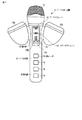
図3(a)は、マイクロホン装置10の音声入出力部14側から見た側面図である。
図3(a)に示すように、2つのスピーカ部13a,13bは、マイク本体部12の軸に対して対象な位置に設けられ、その開口部がマイク本体部12の軸に対して所定の角度をもって、音声入出力部14側(利用者側)を向くように取り付けられている。スピーカ部13a,13bは、指向性を有しており、出力された音が聞こえる範囲(指向範囲)内に歌唱者の耳が入った状態にある場合、音量レベルが高い演奏音を効果的に歌唱者に対して伝達することができる。
FIG. 3A is a side view of the microphone device 10 as viewed from the sound input / output unit 14 side.
As shown in FIG. 3A, the two speaker units 13 a and 13 b are provided at target positions with respect to the axis of the microphone main body 12, and the opening thereof is predetermined with respect to the axis of the microphone main body 12. It is attached so as to face the voice input / output unit 14 side (user side) with an angle. The speaker units 13a and 13b have directivity, and when the singer's ear is in the range where the output sound can be heard (directional range), the performance sound having a high volume level is effectively transmitted. Can be transmitted to the singer.

図4は、マイクロホン装置10を使用している時の歌唱者との位置関係と、マイクロホン装置10の具体的な構成の一例を示している。図4は、歌唱者がマイクロホン装置10(マイク本体部12)を水平となるように保持し、音声入出力部14の先端部(風防部分)を口に近接(あるいは接触)させた状態となっている例を示している。すなわち、近年のプロのミュージシャンがしているような持ち方をしている例である。   FIG. 4 shows an example of the positional relationship with the singer when using the microphone device 10 and a specific configuration of the microphone device 10. FIG. 4 shows a state in which the singer holds the microphone device 10 (microphone main body portion 12) so as to be horizontal, and the tip (windshield portion) of the voice input / output unit 14 is brought close to (or in contact with) the mouth. An example is shown. In other words, it is an example of how it is held like a professional musician in recent years.

図4に示す具体的な構成では、標準的な歌唱者の両耳間の距離をAITS人体データベースに基づいて145.5mmとし、これを基準として頭のサイズが最大と想定される歌唱者に対しても、スピーカ部13から出力されるカラオケ音声によって包まれる感覚を得られるように、スピーカ部13のマイク本体部12に取り付ける位置と向きを決定する(AITS:Advanced Industrial Science and Technology(産業技術総合研究所))。   In the specific configuration shown in FIG. 4, the distance between both ears of a standard singer is 145.5 mm based on the AITS human body database, and for a singer whose head size is assumed to be maximum based on this distance. However, the position and orientation of the speaker unit 13 attached to the microphone main body 12 are determined so as to obtain a sensation wrapped by the karaoke sound output from the speaker unit 13 (AITS: Advanced Industrial Science and Technology). Institute)).

図4に示す例では、音声入出力部14の先端部からスピーカ部13の開口面中心までの、マイク本体部12の軸方向への距離を47mmとしている。すなわち、歌唱者の口元からスピーカ部13までの距離をある程度空けることによって、心理的な圧迫感を軽減している。図3では、音声入出力部14の先端部からスピーカ部13の開口面中心までの距離を47mmとしているが30mm以上確保することが好ましい。   In the example shown in FIG. 4, the distance in the axial direction of the microphone main body 12 from the distal end of the audio input / output unit 14 to the center of the opening surface of the speaker 13 is 47 mm. That is, the feeling of oppressive feeling is reduced by increasing the distance from the singer's mouth to the speaker unit 13 to some extent. In FIG. 3, the distance from the front end of the voice input / output unit 14 to the center of the opening surface of the speaker unit 13 is 47 mm, but it is preferable to secure 30 mm or more.

また、スピーカ部13a,13bは、マイク本体部12に対して、マイク本体部12の軸線上に決められる音声入出力部14の先端部から169.5mmの点(スピーカ部13の開口面中心からマイク本体部12の軸方向への距離が122.5mmの点)から、マイク本体部12の軸に対して左右それぞれ25度の方向の線上に、スピーカ部13a,13bの中心軸をそれぞれ合わせて取り付けている。この場合、2つのスピーカ部13a,13bの開口面中心間の距離は114mmとなる。   In addition, the speaker units 13 a and 13 b are 169.5 mm from the tip of the audio input / output unit 14 determined on the axis of the microphone body 12 with respect to the microphone body 12 (from the center of the opening surface of the speaker 13). The central axis of the speaker units 13a and 13b is aligned on a line in the direction of 25 degrees to the left and right with respect to the axis of the microphone body 12 from the point that the distance in the axial direction of the microphone body 12 is 122.5 mm. It is attached. In this case, the distance between the opening surface centers of the two speaker portions 13a and 13b is 114 mm.

前述のように構成することで、図3に示すスピーカ部13aの指向範囲25aと、スピーカ部13bの指向範囲25bには、歌唱者の左右の耳がそれぞれ含まれるようになる。   By configuring as described above, the directional range 25a of the speaker unit 13a and the directional range 25b of the speaker unit 13b shown in FIG. 3 include the left and right ears of the singer, respectively.

なお、図4に示す例では、スピーカ部13a,13bをマイク本体部12に取り付ける際のスピーカ部13a,13bの中心軸の方向を25度としているが、17度から35度以下の範囲とすることが望ましい。スピーカ部13a,13bの中心軸の方向は、スピーカ部13a,13bの指向性、マイク本体部12に対する取り付け位置、想定される利用者の頭の大きさ(両耳の位置)などの違いにより、それらの組合せに応じて適宜決定することができる。   In the example shown in FIG. 4, the direction of the central axis of the speaker portions 13a and 13b when the speaker portions 13a and 13b are attached to the microphone main body portion 12 is 25 degrees, but the range is 17 degrees to 35 degrees or less. It is desirable. The direction of the central axis of the speaker units 13a and 13b depends on the directivity of the speaker units 13a and 13b, the mounting position with respect to the microphone main body unit 12, the assumed user's head size (position of both ears), and the like. It can be determined as appropriate according to the combination.

要するに、スピーカ部13a,13bは、歌唱者が音声入出力部14(マイク)に口を近接させた状態において、スピーカ部13a,13bから出力される音声が聞こえる指向範囲内に歌唱者の耳が含まれる向きで、マイク本体部12に取り付けられるものとする。   In short, the speaker units 13a and 13b have the singer's ear within the directivity range where the sound output from the speaker units 13a and 13b can be heard in the state where the singer has his mouth close to the voice input / output unit 14 (microphone). It is assumed that the microphone body 12 is attached in the included orientation.

なお、理想的には、歌唱者がマイクロホン装置10を使用している状態において、スピーカ部13a,13bの中心軸の延長線上に歌唱者の耳が位置している場合に、最も効率的にスピーカ部13a,13bから出力されるカラオケ音声を歌唱者に伝達することができる。従って、マイクロホン装置10を使用する利用者が特定されている場合には、その利用者の頭のサイズ、歌唱時の音声入出力部14と口との距離に合わせて、スピーカ部13a,13bのマイク本体部12に対する取り付け位置、スピーカ部13a,13bの向きを決定して、利用者専用のマイクロホン装置10を構成することも可能である。   Ideally, when the singer uses the microphone device 10, the speaker is most efficiently used when the singer's ear is positioned on the extension line of the central axis of the speaker units 13a and 13b. Karaoke sound output from the sections 13a and 13b can be transmitted to the singer. Therefore, when the user who uses the microphone device 10 is specified, the speaker units 13a and 13b are adjusted according to the size of the user's head and the distance between the voice input / output unit 14 and the mouth when singing. It is also possible to configure the microphone device 10 dedicated to the user by determining the attachment position with respect to the microphone main body 12 and the orientation of the speaker portions 13a and 13b.

さらに、スピーカ部13a,13bの向きを微調整することができる可動機構を設けるようにすることで、歌唱者の頭の大きさ、歌唱時の音声入出力部14と口との距離、歌唱時にマイクロホン装置10を保持する角度などの違いに対応して、スピーカ部13a,13bの指向範囲内に歌唱者の耳が含まれるように調整することが可能となる。   Furthermore, by providing a movable mechanism that can finely adjust the direction of the speaker units 13a and 13b, the size of the singer's head, the distance between the voice input / output unit 14 and the mouth during singing, and during singing Corresponding to the difference of the angle etc. which hold | maintain the microphone apparatus 10, it becomes possible to adjust so that a singer's ear may be included in the directivity range of the speaker parts 13a and 13b.

次に、マイクロホン装置10が使用される状態を検出する状態検出機能について説明する。
本実施形態におけるマイクロホン装置10では、2つのスピーカ部13a,13bを設けてステレオ音声を出力するもので、操作部17が設けられた表側を上に向けた状態で使用する通常状態では、スピーカ部13aからはRチャンネルの音声、スピーカ部13bからLチャンネルの音声を出力する。これにより、ステレオ音声を正しく歌唱者に伝達することができる。しかし、利用者によっては、表側を下に向けた状態(裏返し)でマイクロホン装置10を持って使用することも考えられる。本実施形態におけるマイクロホン装置10では、通常状態での使用形態だけでなく、裏返しで使用された場合であっても、歌唱者に対して正しくステレオ音声を伝達することができるように、マイクロホン装置10が使用される状態を検出する状態検出機能が設けられている。
Next, a state detection function for detecting a state in which the microphone device 10 is used will be described.
In the microphone device 10 according to the present embodiment, two speaker units 13a and 13b are provided to output stereo sound. In a normal state where the front side provided with the operation unit 17 is turned up, the speaker unit The sound of R channel is output from 13a, and the sound of L channel is output from the speaker unit 13b. Thereby, stereo sound can be correctly transmitted to a singer. However, depending on the user, it may be considered that the microphone device 10 is used with the front side facing down (inside-down). In the microphone device 10 according to this embodiment, the microphone device 10 can correctly transmit stereo sound to the singer even when the microphone device 10 is used not only in the normal state but also when turned upside down. A state detection function for detecting a state in which the is used is provided.

状態検出機能は、スピーカ部13aがマイク本体部12の軸に対して右側にあり、スピーカ部13bがマイク本体部12の軸に対して左側にある第1の状態(通常状態)と、スピーカ部13aがマイク本体部12の軸に対して左側にあり、スピーカ部13bがマイク本体部12の軸に対して右側にある第2の状態(裏返しの状態)の何れにあるかを検出するもので、本実施形態ではマイク本体部12(把持部15)に設けられた接触センサ16による検出状態をもとに状態を検出する。   The state detection function includes a first state (normal state) in which the speaker unit 13a is on the right side with respect to the axis of the microphone main body unit 12 and the speaker unit 13b is on the left side with respect to the axis of the microphone main unit unit 12; It is for detecting whether the second state (inverted state) in which 13a is on the left side with respect to the axis of the microphone main body portion 12 and the speaker portion 13b is on the right side with respect to the axis of the microphone main body portion 12. In this embodiment, the state is detected based on the detection state by the contact sensor 16 provided in the microphone main body 12 (gripping part 15).

マイクロホン装置10の内部に設けられた音声処理回路には、状態検出機能により第1の状態あるいは第2の状態の何れが検出されたかに応じて、スピーカ部13a,13bから出力させる音声の音声信号を交換する信号交換回路が設けられている。   The audio processing circuit provided inside the microphone device 10 has an audio signal to be output from the speaker units 13a and 13b depending on whether the first state or the second state is detected by the state detection function. A signal exchange circuit for exchanging the signals is provided.

図5には、マイクロホン装置10の状態を検出するために用いられる接触センサ16の一例を示す図である。図5(a)は、マイク本体部12の表側(操作部17が設けられている側)に設けられた接触センサ16の一例を示すもので、例えば4つのセンサSa1,Sa2,Sa3,Sa4が直列上にそれぞれ離間させて配置されている。また、図5(b)のマイク本体部12底部側から見た図に示すように、マイク本体部12裏側には、表側に設けられた4つのセンサSa1,Sa2,Sa3,Sa4と相対する位置に、4つのセンサSb1,Sb2,Sb3,Sb4が直列上にそれぞれ離間させて配置されている。   FIG. 5 is a diagram illustrating an example of the contact sensor 16 used for detecting the state of the microphone device 10. FIG. 5A shows an example of the contact sensor 16 provided on the front side of the microphone main body 12 (the side on which the operation unit 17 is provided). For example, four sensors Sa1, Sa2, Sa3, Sa4 are included. They are arranged apart from each other in series. Moreover, as shown in the figure seen from the bottom side of the microphone main body 12 in FIG. 5B, the back side of the microphone main body 12 is positioned opposite to the four sensors Sa1, Sa2, Sa3, Sa4 provided on the front side. In addition, four sensors Sb1, Sb2, Sb3, and Sb4 are arranged apart from each other in series.

通常、歌唱者がマイクロホン装置10の把持部15の部分を把持した場合、手のひらと指で覆いきれない部分が発生する。すなわち、把持部15の表側は人差し指、中指、薬指、小指によって第2及び第3関節部分辺りで覆われるが、裏側では親指のみによって覆われることになる。マイクロホン装置10は、表側のセンサSa1,Sa2,Sa3,Sa4と裏側のSb1,Sb2,Sb3,Sb4のそれぞれにおいて検出される接触部と非接触部とを比較し、利用者が接触していることを検出しているセンサの数が多い方を上向きにして使用しているものとして使用状態を判別する。なお、表側と裏側のセンサによる検出結果が同じ場合には、通常状態(デフォルト状態)で保持されているものと判別するものとする。   Usually, when the singer grips the grip portion 15 of the microphone device 10, a portion that cannot be covered with the palm and fingers is generated. That is, the front side of the grip portion 15 is covered by the index finger, middle finger, ring finger, and little finger around the second and third joint portions, but the back side is covered only by the thumb. The microphone device 10 compares the contact portions detected in the front side sensors Sa1, Sa2, Sa3, Sa4 and the back side Sb1, Sb2, Sb3, Sb4 with the non-contact portions, and the user is in contact The use state is determined on the assumption that the sensor with the larger number of sensors detecting is used upward. When the detection results of the front side sensor and the back side sensor are the same, it is determined that the sensor is held in the normal state (default state).

次に、マイクロホン装置10に設けられた音声処理回路の構成について説明する。図6は、マイクロホン装置10の音声処理回路の構成を示すブロック図である。   Next, the configuration of the sound processing circuit provided in the microphone device 10 will be described. FIG. 6 is a block diagram showing a configuration of a sound processing circuit of the microphone device 10.

マイクロホン装置10には、外部から入力された音声信号に対して演奏音エフェクトを付加してスピーカ部13a,13bから音声を出力させ、またマイク14aによって入力された音声信号に対してエフェクトを付加して外部に出力するための信号処理を行う音声処理回路29が設けられている。この音声処理回路29における信号処理は、マイクロコントローラ30によって制御される。マイクロコントローラ30は、操作スイッチブロック31に含まれるスピーカボリューム21、マイクボリューム20、上ボタン22a、下ボタン22bに対する操作に応じて、マイクエフェクト付加回路37、演奏音エフェクト付加回路61を含む各回路における信号処理を制御する。   The microphone device 10 adds a performance sound effect to a sound signal input from the outside to output sound from the speaker units 13a and 13b, and adds an effect to the sound signal input by the microphone 14a. And an audio processing circuit 29 for performing signal processing for output to the outside. Signal processing in the audio processing circuit 29 is controlled by the microcontroller 30. The microcontroller 30 includes a microphone effect addition circuit 37 and a performance sound effect addition circuit 61 in response to operations on the speaker volume 21, the microphone volume 20, the upper button 22a, and the lower button 22b included in the operation switch block 31. Control signal processing.

なお、上ボタン22aと下ボタン22bに対する操作によって、マイクエフェクト付加回路37によるマイクエフェクトと演奏音エフェクト付加回路61による演奏音エフェクトを示すエフェクトモードが設定され、マイクロコントローラ30は、エフェクトモードに応じて各部を制御する。   By operating the upper button 22a and the lower button 22b, an effect mode indicating a microphone effect by the microphone effect addition circuit 37 and a performance sound effect by the performance sound effect addition circuit 61 is set, and the microcontroller 30 responds to the effect mode. Control each part.

図6に示すように、マイク14aから入力された音声信号は、アンプ回路35により増幅され、マイクロコントローラ30により制御されるアッテネータ回路(以下、ATT)36により信号レベルが調整されてマイクエフェクト付加回路37に入力される。マイクエフェクト付加回路37は、ATT36から入力される音声信号に対して、マイクロコントローラ30からの指示に応じたエコーやピッチシフトなどの音響効果(マイクエフェクト)を付加して、マイクのLチャンネルとRチャンネルの信号を2つのミキシング回路38,39に出力する。   As shown in FIG. 6, the audio signal input from the microphone 14a is amplified by the amplifier circuit 35, and the signal level is adjusted by the attenuator circuit (hereinafter referred to as ATT) 36 controlled by the microcontroller 30, so that the microphone effect addition circuit. 37. The microphone effect addition circuit 37 adds an acoustic effect (microphone effect) such as echo or pitch shift according to an instruction from the microcontroller 30 to the audio signal input from the ATT 36, and the L channel and R of the microphone. The channel signal is output to the two mixing circuits 38 and 39.

一方、端子45から入力された外部機器からのLチャンネルの音声信号(カラオケ音声)は、アンプ回路46によって増幅され、ATT47により信号レベルが調整されてチャンネル交換回路回路(以下、CHSWEAP回路)60に入力される。同様にして、端子48から入力されたRチャンネルの音声信号は、アンプ回路49、ATT50を介してCHSWEAP回路60に入力される。   On the other hand, the L channel audio signal (karaoke audio) input from the terminal 45 is amplified by the amplifier circuit 46, the signal level is adjusted by the ATT 47, and the channel switching circuit circuit (hereinafter referred to as CHSWEAP circuit) 60 is supplied. Entered. Similarly, the R channel audio signal input from the terminal 48 is input to the CHSWEAP circuit 60 via the amplifier circuit 49 and the ATT 50.

CHSWEAP回路60は、マイクロコントローラ30からの制御に応じて、ATT47,50を介して入力された音声信号のL/Rチャンネルを交換する。マイクロコントローラ30は、接触センサユニット70によって検出される接触センサ16(Sa1,Sa2,Sa3,Sa4、Sb1,Sb2,Sb3,Sb4)からの検出結果をもとに、マイクロホン装置10の使用状態(第1の状態、第2の状態)を判別して音声信号のL/Rチャンネルの交換を制御する。すなわち、マイクロコントローラ30は、第1の状態(通常状態)の場合には、チャンネルの交換を行わず、第2の状態の場合には、端子48から入力されたRチャンネルの音声信号をスピーカ部13bから音声を出力させるための信号として出力し、端子45から入力されたLチャンネルの音声信号をスピーカ部13aから音声を出力させるための信号として出力する、
演奏音エフェクト付加回路61は、マイクロコントローラ30の制御に応じて、CHSWEAP回路60から出力される音声信号に対して、マイクロコントローラ30からの指示に応じたエコーやエフェクトなどの音響効果を付加して2つのミキシング回路38,39に出力する。また、演奏音エフェクト付加回路61は、マイクロコントローラ30の制御に応じて、音声信号に含まれるボーカル部分を除去するボーカルカットの音声処理を実行することができる。これにより、外部からボーカルが含まれている音声信号が入力される場合であっても、この音声信号からボーカルをカットしたカラオケ音声をスピーカ部13から出力させることができる。
The CHSWEAP circuit 60 exchanges the L / R channel of the audio signal input via the ATTs 47 and 50 in accordance with the control from the microcontroller 30. Based on the detection results from the contact sensors 16 (Sa1, Sa2, Sa3, Sa4, Sb1, Sb2, Sb3, Sb4) detected by the contact sensor unit 70, the microcontroller 30 uses the microphone device 10 in the use state (first order). 1 state and 2nd state) are discriminated, and the exchange of the L / R channel of the audio signal is controlled. That is, in the first state (normal state), the microcontroller 30 does not exchange channels, and in the second state, the microcontroller 30 receives the R channel audio signal input from the terminal 48. 13b is output as a signal for outputting sound, and an L channel audio signal input from the terminal 45 is output as a signal for outputting sound from the speaker unit 13a.
The performance sound effect adding circuit 61 adds an acoustic effect such as an echo or an effect according to an instruction from the microcontroller 30 to the audio signal output from the CHSWEAP circuit 60 according to the control of the microcontroller 30. It outputs to two mixing circuits 38 and 39. Further, the performance sound effect adding circuit 61 can execute vocal cut voice processing for removing a vocal portion included in the voice signal under the control of the microcontroller 30. Thereby, even when a voice signal including vocal is input from the outside, karaoke voice obtained by cutting vocal from this voice signal can be output from the speaker unit 13.

ミキシング回路38は、マイクエフェクト付加回路37から出力されたマイク14aから入力された音声の音声信号と、演奏音エフェクト付加回路61から出力された一方のチャンネルの音声信号(カラオケ音声)とを合成してATT63に出力する。ATT63は、ミキシング回路38から出力された入力音声のレベルを調整して、スピーカドライブ用のアンプ回路64(SP Amp.)に出力する。アンプ回路64は、スピーカボリューム21の操作に応じたマイクロコントローラ30の制御に応じて、ATT63から出力される音声信号を増幅してスピーカ部13bから音声を出力させる。   The mixing circuit 38 synthesizes the sound signal of the sound input from the microphone 14 a output from the microphone effect addition circuit 37 and the sound signal (karaoke sound) of one channel output from the performance sound effect addition circuit 61. Output to ATT63. The ATT 63 adjusts the level of the input sound output from the mixing circuit 38 and outputs it to the amplifier circuit 64 (SP Amp.) For speaker drive. The amplifier circuit 64 amplifies the audio signal output from the ATT 63 under the control of the microcontroller 30 according to the operation of the speaker volume 21, and outputs the audio from the speaker unit 13b.

同様にして、ミキシング回路39は、マイクエフェクト付加回路37から出力されたマイク14aから入力された音声の音声信号と、演奏音エフェクト付加回路61から出力された他方のチャンネルの音声信号(カラオケ音声)とを合成してATT63に出力する。ATT65は、ミキシング回路39から出力された入力音声のレベルを調整して、スピーカドライブ用のアンプ回路66(SP Amp.)に出力する。アンプ回路66は、スピーカボリューム21の操作に応じたマイクロコントローラ30の制御に応じて、ATT65から出力される音声信号を増幅してスピーカ部13aから音声を出力させる。   Similarly, the mixing circuit 39 outputs the sound signal of the sound input from the microphone 14a output from the microphone effect addition circuit 37 and the sound signal (karaoke sound) of the other channel output from the performance sound effect addition circuit 61. Are combined and output to the ATT 63. The ATT 65 adjusts the level of the input sound output from the mixing circuit 39 and outputs it to the speaker drive amplifier circuit 66 (SP Amp.). The amplifier circuit 66 amplifies the audio signal output from the ATT 65 according to the control of the microcontroller 30 according to the operation of the speaker volume 21, and outputs the audio from the speaker unit 13a.

また、ミキシング回路38から出力される音声信号は、ATT40を介して出力端子68から外部に出力され、ミキシング回路39から出力される音声信号は、ATT41を介して出力端子69から外部に出力される。ATT40,41は、マイクロコントローラ30の制御に応じて、出力端子68,69から外部に出力する音声信号の信号レベルを調整する。マイクロコントローラ30は、電池ボックス72を介して他の1本のマイクロホン装置74と接続された場合には、例えば出力する音声信号のレベルを1/2に下げるように制御する。すなわち、本実施形態では、カラオケをデュエットするような時に、後述する電池ボックス72を利用することで、同時に2本のマイクロホン装置10,74を使用できるようにし、電池ボックス72においてマイクロホン装置10,74から出力された音声信号を合成して外部のオーディオ機器(テレビ、ステレオシステムなど)などに出力させる。この場合、マイクロホン装置10,74が1本で使用する時と同じ信号レベルで出力して、電池ボックス72において単純に音声信号を合成出力してしまうと、オーディオ機器に対して出力される音声信号のレベルが通常の2倍となってしまう。そこで、マイクロホン装置10は、他のマイクロホン装置74が接続された場合に、予め信号レベルを1/2として音声信号を出力することで、電池ボックス72における音声レベル調整のための特別な機能を不要として単純な音声信号の合成だけで良くなる。   The audio signal output from the mixing circuit 38 is output to the outside from the output terminal 68 via the ATT 40, and the audio signal output from the mixing circuit 39 is output to the outside from the output terminal 69 via the ATT 41. . The ATTs 40 and 41 adjust the signal level of the audio signal output from the output terminals 68 and 69 to the outside according to the control of the microcontroller 30. When the microcontroller 30 is connected to another microphone device 74 via the battery box 72, the microcontroller 30 controls, for example, to lower the level of the output audio signal to ½. That is, in the present embodiment, when performing duet of karaoke, a battery box 72 described later is used so that two microphone devices 10 and 74 can be used at the same time. The audio signal output from is synthesized and output to an external audio device (TV, stereo system, etc.). In this case, if the microphone devices 10 and 74 are output at the same signal level as when the microphone devices 10 and 74 are used alone, and the audio signal is simply synthesized and output in the battery box 72, the audio signal output to the audio device is output. Will be twice the normal level. Therefore, the microphone device 10 does not need a special function for adjusting the sound level in the battery box 72 by outputting a sound signal with a signal level halved in advance when another microphone device 74 is connected. As a result, simple speech signal synthesis is sufficient.

電池ボックス72は、マイクロホン装置10,74に対して電力を供給すると共に、マイクロホン装置10,74と他の音響機器との間に介在して、オーディオ機器からマイクロホン装置10へのカラオケ音声の供給、及びマイクロホン装置10,74から入力された音声信号のオーディオ機器への供給を仲介する。
なお、図6に示すマイクロホン装置74は、前述したマイクロホン装置10と同様の構成を有するものとして説明を省略する。
The battery box 72 supplies power to the microphone devices 10 and 74 and is interposed between the microphone devices 10 and 74 and other acoustic devices to supply karaoke sound from the audio device to the microphone device 10. In addition, it mediates the supply of audio signals input from the microphone devices 10 and 74 to the audio equipment.
Note that the microphone device 74 shown in FIG. 6 has the same configuration as the microphone device 10 described above, and a description thereof will be omitted.

次に、本実施形態におけるマイクロホン装置10をカラオケ時に使用する場合について説明する。
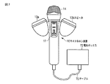
マイクロホン装置10を使用する場合には、図7に示すように、ケーブル75を介して電池ボックス72と接続する。マイクロホン装置10の底部には、図8(a)に示すように、複数の信号端子を含むコネクタ10aが設けられており、このコネクタ10aにケーブル75が接続される。コネクタ10aに含まれる端子には、音声信号入力用の端子45,48、音声信号出力用の端子68,69、電池ボックス72におけるマイクロホン装置の接続の有無を表す制御信号用の端子、電力供給用の端子などが含まれている。
Next, the case where the microphone device 10 according to the present embodiment is used during karaoke will be described.
When the microphone device 10 is used, it is connected to the battery box 72 via a cable 75 as shown in FIG. As shown in FIG. 8A, a connector 10a including a plurality of signal terminals is provided at the bottom of the microphone device 10, and a cable 75 is connected to the connector 10a. The terminals included in the connector 10a include audio signal input terminals 45 and 48, audio signal output terminals 68 and 69, a control signal terminal indicating whether or not the microphone device is connected to the battery box 72, and a power supply terminal. Terminal etc. are included.

一方、電池ボックス72には、図8(b)に示すように、2本のマイクロホン装置10,74を接続するための2つのコネクタ72a,72bが設けられている。ケーブル75は、コネクタ72a,72bの何れか一方に接続される。   On the other hand, the battery box 72 is provided with two connectors 72a and 72b for connecting the two microphone devices 10 and 74, as shown in FIG. The cable 75 is connected to one of the connectors 72a and 72b.

また、電池ボックス72には、外部機器からの音声信号を入力するための端子72c(45,48)と、マイクロホン装置10において入力された音声信号を外部機器に出力するための端子72d(68,69)が設けられている。端子72c,72dには、音声信号用のゲーブルが外部機器との間で接続される。   Also, the battery box 72 has terminals 72c (45, 48) for inputting audio signals from external devices, and terminals 72d (68, 48) for outputting audio signals input in the microphone device 10 to the external devices. 69). The audio signal gable is connected to the terminals 72c and 72d with an external device.

図9には、1本のマイクロホン装置10を使用する場合の外部機器との接続例を示している。
図9に示すように、マイクロホン装置10は、電池ボックス72に接続される。電池ボックス72には、カラオケ音声の音源を再生するためのオーディオ装置80(例えばテレビ装置)と、カラオケ音声とマイクロホン装置10から入力された音声とが合成された音声を出力するためのオーディオ装置81(例えばステレオシステム)とが接続される。
FIG. 9 shows an example of connection with an external device when one microphone device 10 is used.
As shown in FIG. 9, the microphone device 10 is connected to a battery box 72. The battery box 72 has an audio device 80 (for example, a television device) for reproducing a sound source of karaoke sound, and an audio device 81 for outputting a sound in which the karaoke sound and the sound input from the microphone device 10 are synthesized. (For example, a stereo system) is connected.

図9に示す例では、オーディオ装置80においてカラオケ用の音源を再生することにより、オーディオ装置80から電池ボックス72を通じてマイクロホン装置10に音声信号が出力される。マイクロホン装置10は、電池ボックス72を通じて入力された音声信号をスピーカ部13a,13bから出力させる。オーディオ装置80において再生された音源に歌唱音声が含まれている場合には、マイクロホン装置10において上ボタン22aと下ボタン22bを操作して演奏音エフェクトとしてボーカルカットを指定することにより、歌唱音声が除去されたカラオケ音声をスピーカ部13から出力させることができる。   In the example shown in FIG. 9, a sound signal for karaoke is reproduced in the audio device 80, whereby an audio signal is output from the audio device 80 to the microphone device 10 through the battery box 72. The microphone device 10 outputs the audio signal input through the battery box 72 from the speaker units 13a and 13b. When the sound source reproduced by the audio device 80 includes a singing voice, the singing voice is specified by operating the upper button 22a and the lower button 22b on the microphone device 10 to specify vocal cut as a performance sound effect. The removed karaoke voice can be output from the speaker unit 13.

利用者は、スピーカ部13から出力されるカラオケ音声を聞きながら歌唱することにより、マイクロホン装置10から音声を入力する。マイクロホン装置10は、音声入出力部14(マイク14a)から入力された音声の音声信号を、ミキシング回路38,39によってカラオケ音声に合成する。従って、利用者は、スピーカ部13から出力される音声によって自分の声をモニタしながら歌唱することができる。   The user inputs voice from the microphone device 10 by singing while listening to the karaoke voice output from the speaker unit 13. The microphone device 10 synthesizes the voice signal of the voice input from the voice input / output unit 14 (microphone 14a) with the karaoke voice by the mixing circuits 38 and 39. Therefore, the user can sing while monitoring his / her voice by the sound output from the speaker unit 13.

マイクロホン装置10(出力端子68,69)から出力される音声信号は、電池ボックス72を介して、オーディオ装置81に出力される。マイクロホン装置10から出力される音声信号にはカラオケ音声に利用者による歌唱音声が合成されているので、オーディオ装置81は、マイクロホン装置10から出力された音声信号に応じた音声を出力させることで、カラオケ音声と歌唱音声とを出力することができる。これにより、マイクロホン装置10を使用している歌唱者だけでなく、周辺にいる他の人と一緒にカラオケを楽しむことができる。   Audio signals output from the microphone device 10 (output terminals 68 and 69) are output to the audio device 81 via the battery box 72. Since the singing voice by the user is synthesized with the karaoke voice in the voice signal output from the microphone device 10, the audio device 81 outputs the voice corresponding to the voice signal output from the microphone device 10, Karaoke voice and singing voice can be output. Thereby, it is possible to enjoy karaoke with not only a singer who uses the microphone device 10 but also other people in the vicinity.

図10には、2本のマイクロホン装置10を使用する場合の外部機器との接続例を示している。これは2人の利用者によりデュエットなどをする場合に用いられる使用形態である。   FIG. 10 shows an example of connection with an external device when two microphone devices 10 are used. This is a usage pattern used when a duet is performed by two users.

図10に示すように、2本のマイクロホン装置10,74は、それぞれ電池ボックス72に接続される。電池ボックス72には、図9と同様にして、カラオケ音声の音源を再生するためのオーディオ装置80(例えばテレビ装置)と、カラオケ音声とマイクロホン装置10から入力された音声とが合成された音声を出力するためのオーディオ装置81(例えばステレオシステム)とが接続される。   As shown in FIG. 10, the two microphone devices 10 and 74 are each connected to the battery box 72. Similarly to FIG. 9, the battery box 72 has an audio device 80 (for example, a television device) for reproducing a sound source of karaoke sound, and a sound obtained by synthesizing the karaoke sound and the sound input from the microphone device 10. An audio device 81 (for example, a stereo system) for output is connected.

図10に示す例では、オーディオ装置80においてカラオケ用の音源を再生することにより、オーディオ装置80から電池ボックス72を通じてマイクロホン装置10に音声信号が出力される。   In the example illustrated in FIG. 10, a sound signal for karaoke is reproduced in the audio device 80, whereby an audio signal is output from the audio device 80 to the microphone device 10 through the battery box 72.

マイクロホン装置10,74は、前述と同様にして、それぞれ電池ボックス72を通じて入力された音声信号をスピーカ部13a,13bから出力させる。なお、マイクロホン装置10のスピーカ部13からは、マイクロホン装置10の利用者の歌唱音がカラオケ音声に合成されて出力され、マイクロホン装置74のスピーカ部13からは、マイクロホン装置74の利用者の歌唱音がカラオケ音声に合成されて出力される。従って、マイクロホン装置10,74の利用者は、個々に、スピーカ部13から出力される自分の声のみをモニタしながら歌唱することができる。   In the same manner as described above, the microphone devices 10 and 74 output the audio signals input through the battery box 72 from the speaker units 13a and 13b, respectively. Note that the singing sound of the user of the microphone device 10 is synthesized with the karaoke voice and output from the speaker unit 13 of the microphone device 10, and the singing sound of the user of the microphone device 74 is output from the speaker unit 13 of the microphone device 74. Is synthesized with karaoke voice and output. Therefore, the users of the microphone devices 10 and 74 can individually sing while monitoring only their own voice output from the speaker unit 13.

一方、電池ボックス72は、マイクロホン装置10,74から出力された音声を合成してオーディオ装置81に出力するので、オーディオ装置81に出力される音声信号には、マイクロホン装置10,74の両方の利用者による歌唱音が含まれる。   On the other hand, since the battery box 72 synthesizes the sound output from the microphone devices 10 and 74 and outputs the synthesized sound to the audio device 81, the sound signal output to the audio device 81 uses both of the microphone devices 10 and 74. The singing sound by a person is included.

図11は、電池ボックス72の音声信号に対する機能を示すブロック図である。
図11に示すように、電池ボックス72には、外部機器(オーディオ装置80)から入力された音声信号を、2つのマイクロホン装置10,74に分配して出力する音声分配部72aと、マイクロホン装置10,74により入力された音声の音声信号を合成して外部機器(オーディオ装置81)に出力する音声合成部72bが設けられる。本実施形態では、マイクロホン装置10において音声信号に対するレベル調整やエフェクト処理を実行するものとし、電池ボックス72においては単純な音声信号の分配/合成処理を実行するものとする。音声合成部72bに入力されるマイクロホン装置10,74からの音声信号は、予め合成後の音声レベルが適切となるようにレベル調整がされている。
FIG. 11 is a block diagram showing the function of the battery box 72 for the audio signal.
As shown in FIG. 11, the battery box 72 includes an audio distribution unit 72 a that distributes audio signals input from an external device (audio device 80) to the two microphone devices 10 and 74, and the microphone device 10. , 74 and a voice synthesizer 72b for synthesizing the voice signals of the voices input to the external device (audio device 81). In the present embodiment, the microphone device 10 performs level adjustment and effect processing on the audio signal, and the battery box 72 executes simple audio signal distribution / synthesis processing. The audio signals from the microphone devices 10 and 74 that are input to the audio synthesis unit 72b are adjusted in advance so that the synthesized audio level is appropriate.

また、図11には、図示していないが、電池ボックス72の端子72a,72bとマイクロホン装置10,74がケーブルを介して接続されることにより、他のマイクロホン装置の接続の有無を表す制御信号がマイクロホン装置10,74に出力される。マイクロホン装置10,74のマイクロコントローラ30は、この制御信号をもとにして、自装置の他にマイクロホン装置が電池ボックス72に接続されたことを検出すると、ATT40,41を制御して、電池ボックス72に出力される音声信号の信号レベルを例えば1/2にして、電池ボックス72における合成後の音声レベルが適切となるようにレベル調整をする。   In addition, although not shown in FIG. 11, a control signal indicating whether or not another microphone device is connected by connecting the terminals 72 a and 72 b of the battery box 72 and the microphone devices 10 and 74 via a cable. Is output to the microphone devices 10 and 74. When the microcontroller 30 of the microphone devices 10 and 74 detects that the microphone device is connected to the battery box 72 in addition to its own device based on this control signal, it controls the ATTs 40 and 41 to control the battery box. The signal level of the audio signal output to 72 is halved, for example, and the level is adjusted so that the synthesized audio level in the battery box 72 is appropriate.

次に、マイクロホン装置10における演奏音エフェクトの具体例について説明する。
マイクロホン装置10では、上ボタン22aと下ボタン22bの操作によってエフェクトモードを指定することによって、マイク音に対するマイクエフェクトやカラオケ音声に対する演奏音エフェクトを付加することができる。マイクエフェクトとしては、例えばエコーの付加があり、複数種類のエコー(やまびこ、ホール、…)を選択することができる。
Next, a specific example of the performance sound effect in the microphone device 10 will be described.
In the microphone device 10, by specifying the effect mode by operating the upper button 22a and the lower button 22b, a microphone effect for the microphone sound and a performance sound effect for the karaoke sound can be added. As the microphone effect, for example, an echo is added, and a plurality of types of echoes (Yamabiko, Hall,...) Can be selected.

また、演奏音エフェクトとしては、前述したボーカルカットの他、利用者の年代別の聴力レベルに基づいて音声信号に対して補正を行うことによって、年代に関係なく誰もがスピーカ部13から出力されるカラオケ音声を聞きやすくするための信号補正がある。   Moreover, as a performance sound effect, in addition to the above-described vocal cut, by correcting the audio signal based on the hearing level of each user's age, anyone is output from the speaker unit 13 regardless of age. There is a signal correction to make it easier to hear karaoke voice.

図12には、聴覚検査によって得られた年代と聴力変化との関係の一例を示す図である。図12に示すように、一般に、年代が上になるほど聴力レベルが低下していく。特に高い周波数域ほど聴力レベルの低下が大きくなる。   FIG. 12 is a diagram showing an example of the relationship between the age obtained by the auditory test and the change in hearing ability. As shown in FIG. 12, the hearing level generally decreases as the age increases. In particular, the lower the hearing level, the higher the frequency range.

このため、マイクロホン装置10のスピーカ部13から出力されカラオケ音声を補正することなく出力した場合、年代が高い利用者ほど、スピーカ部13から出力されたカラオケ音声が聞き取り難く感じるおそれがある。これに対して、本実施形態におけるマイクロホン装置10では、利用者からのエフェクトモードの指定に応じて、利用者の年代別の聴力レベルに基づく補正処理(イコライズ)することにより、年代毎に適切に音量レベルが調整されたカラオケ音声を出力させることができる。   For this reason, when the karaoke sound output from the speaker unit 13 of the microphone device 10 is output without correction, a user with a higher age may feel that the karaoke sound output from the speaker unit 13 is difficult to hear. On the other hand, in the microphone device 10 according to the present embodiment, the correction processing (equalization) based on the hearing level of each user according to the user's specification of the effect mode is performed appropriately for each age. Karaoke sound whose volume level is adjusted can be output.

図13には、マイクロコントローラ30の制御により演奏音エフェクト付加回路61において音声信号を補正するための年代補正特性の一例を示している。マイクロコントローラ30は、図13に示す年代補正特性に基づいて、演奏音エフェクト付加回路61においてカラオケ音声信号に対して、周波数に応じて信号レベルを上げる補正処理を実行させる。   FIG. 13 shows an example of the age correction characteristic for correcting the audio signal in the performance sound effect adding circuit 61 under the control of the microcontroller 30. Based on the age correction characteristic shown in FIG. 13, the microcontroller 30 causes the performance sound effect adding circuit 61 to execute a correction process for increasing the signal level in accordance with the frequency of the karaoke voice signal.

例えば、エフェクトモードとして「50歳代」用の補正が指示された場合には、マイクロコントローラ30は、「50歳代」に対して決められた年代補正特性に応じた信号補正をして、スピーカ部13a,13bから補正されたカラオケ音声を出力させる。   For example, when correction for “50's” is instructed as the effect mode, the microcontroller 30 performs signal correction according to the age correction characteristic determined for “50's”, and the speaker The corrected karaoke sound is output from the units 13a and 13b.

このようにして、マイクロホン装置10では、エフェクトモードとして年代に応じたカラオケ音声に対する補正処理の実行を指定できるので、聴力が衰えた利用者であっても、カラオケ音声を良好な状態で聞きながら歌唱することが可能となる。   In this way, since the microphone device 10 can designate execution of correction processing for karaoke sound according to the age as the effect mode, even a user whose hearing has declined can sing while listening to the karaoke sound in a good state. It becomes possible to do.

なお、聴力特性は、個人差があるので、エフェクトモードとして年代を指定するのではなく、補正モード1,2,…のように複数段階で指定できるようにして、利用者が実際にカラオケ音声を聞きやすいと感じる補正モードを指定できるようにすれば良い。また、マイクエフェクトや演奏音エフェクトを示すエフェクトモードとは別に、補正モードを任意に指定できるようにしても良い。   Since the hearing characteristics vary from person to person, the age is not specified as the effect mode, but it can be specified in multiple stages such as correction modes 1, 2,. A correction mode that feels easy to hear can be specified. In addition to the effect mode indicating the microphone effect and the performance sound effect, the correction mode may be arbitrarily designated.

このようにして、本実施形態におけるマイクロホン装置10では、マイク本体部12の軸に対して対称な位置に2つのスピーカ部13を設けて、スピーカ部13の向きを、マイク本体部12に利用者が口を近接させた状態において、2つのスピーカ部13から音声が出力される指向範囲内に利用者の耳が含まれるように取り付けているので、マイクロホン装置10の持ち方に制約を設けることなく、カラオケ音声を良好な状態で聞きながら歌唱することが可能となる。   As described above, in the microphone device 10 according to the present embodiment, the two speaker units 13 are provided at positions symmetrical with respect to the axis of the microphone main body unit 12, and the direction of the speaker unit 13 is set to the user of the microphone main body unit 12. Is attached so that the user's ear is included in the directivity range in which the sound is output from the two speaker units 13 in a state where the mouths are close to each other, without restricting how to hold the microphone device 10. It becomes possible to sing while listening to the karaoke sound in a good state.

なお、前述した説明では、把持部15の表側と裏側のそれぞれに複数の接触センサ16を設け、利用者による接触の有無をもとにマイクロホン装置10の状態を検出しているが、その他のセンサを設けてマイクロホン装置10の状態(第1状態または第2の状態)を検出するようにしても良い。例えば、マイクロホン装置10そのものの状態を検出するセンサを内蔵することも可能である。   In the above description, a plurality of contact sensors 16 are provided on each of the front side and the back side of the gripping part 15 to detect the state of the microphone device 10 based on the presence or absence of contact by the user. May be provided to detect the state of the microphone device 10 (first state or second state). For example, it is possible to incorporate a sensor for detecting the state of the microphone device 10 itself.

また、前述したマイクロホン装置10の構成では、図2及び図3(a)に示すように、スピーカ部13a,13bの軸とマイク本体部12の軸とが直線上に一致するよう配置されているが、例えば図3(b)に示すように、直線上に一致しないように、スピーカ部13a,13bをマイク本体部12に取り付けるようにしても良い。この場合、マイク本体部12の裏側に2つのスピーカ部13a,13bが偏るように配置する。これにより、歌唱者がマイクロホン装置10を保持する際に、スピーカ部13a,13bが下側にある状態、すなわち裏側が下を向いた第2の状態にすると安定するため、歌唱者が特に意識することなく自然と第2の状態で保持するようになる。このように構成した場合には、状態検出機能や、状態検出機能の検出結果に応じて、スピーカ部13a,13bから出力される音声のチャンネルを交換するCHSWEAP回路60を省いた構成することができる。   Further, in the configuration of the microphone device 10 described above, as shown in FIGS. 2 and 3A, the axes of the speaker units 13a and 13b and the axis of the microphone main body unit 12 are arranged so as to coincide with each other on a straight line. However, for example, as shown in FIG. 3B, the speaker units 13 a and 13 b may be attached to the microphone main body 12 so as not to coincide with each other on a straight line. In this case, it arrange | positions so that the two speaker parts 13a and 13b may be biased in the back side of the microphone main-body part 12. FIG. Thus, when the singer holds the microphone device 10, the speaker unit 13 a, 13 b is stable when the speaker unit 13 a, 13 b is in the lower side, that is, in the second state with the back side facing downward. It will naturally hold in the second state. When configured in this way, it is possible to omit the CHSWEAP circuit 60 for exchanging the audio channels output from the speaker units 13a and 13b in accordance with the state detection function and the detection result of the state detection function. .

また、本発明は上記実施形態そのままに限定されるものではなく、実施段階ではその要旨を逸脱しない範囲で構成要素を変形して具体化できる。また、上記実施形態に開示されている複数の構成要素の適宜な組み合わせにより、種々の発明を形成できる。例えば、実施形態に示される全構成要素から幾つかの構成要素を削除してもよい。さらに、異なる実施形態にわたる構成要素を適宜組み合わせてもよい。   Further, the present invention is not limited to the above-described embodiments as they are, and can be embodied by modifying the constituent elements without departing from the scope of the invention in the implementation stage. In addition, various inventions can be formed by appropriately combining a plurality of components disclosed in the embodiment. For example, some components may be deleted from all the components shown in the embodiment. Furthermore, constituent elements over different embodiments may be appropriately combined.

10,74…マイクロホン装置、12…マイク本体部、13…スピーカ部、14…音声入出力部、14a…マイク14a、15…把持部、16…接触センサ、17…操作部、20…マイクボリューム、21…スピーカボリューム、23…7セグメント表示器、30…マイクロコントローラ、37…マイクエフェクト付加回路、38,39…ミキシング回路、36,40,41,47,50,63,65…ATT、60…CHSWEAP回路、61…演奏音エフェクト付加回路、72…電池ボックス、72a…音声分配部、72b…音声合成部、80,81…オーディオ装置。   DESCRIPTION OF SYMBOLS 10,74 ... Microphone apparatus, 12 ... Microphone main body part, 13 ... Speaker part, 14 ... Voice input / output part, 14a ... Microphone 14a, 15 ... Gripping part, 16 ... Contact sensor, 17 ... Operation part, 20 ... Microphone volume, 21 ... Speaker volume, 23 ... 7-segment display, 30 ... Microcontroller, 37 ... Microphone effect addition circuit, 38, 39 ... Mixing circuit, 36, 40, 41, 47, 50, 63, 65 ... ATT, 60 ... CHSWEAP Circuit 61... Performance sound effect addition circuit 72. Battery box 72 a Sound distribution unit 72 b Speech synthesis unit 80, 81 Audio device

Claims (6)

先端にマイクが装着されたマイク本体部と、
前記マイク本体部の軸に対して対称な位置に配置され、前記マイク本体部に取り付けられた第1及び第2のスピーカと、
前記マイクにより入力された音声の音声信号を外部に出力すると共に、外部から入力される音声信号をもとに前記第1及び第2のスピーカから音声を出力させる音声処理回路と
前記第1のスピーカが前記マイク本体部の軸に対して右側にあり、前記第2のスピーカが前記マイク本体部の軸に対して左側にある第1の状態と、前記第1のスピーカが前記マイク本体部の軸に対して左側にあり、前記第2のスピーカが前記マイク本体部の軸に対して右側にある第2の状態の何れにあるかを検出する状態検出手段とを具備し、
前記音声処理回路は、前記状態検出手段により前記第1の状態あるいは前記第2の状態の何れが検出されたかに応じて、前記第1のスピーカと前記第2のスピーカから出力させる音声の音声信号を交換することを特徴とするマイクロホン装置。
A microphone body with a microphone attached to the tip;
A first speaker and a second speaker, which are arranged at positions symmetrical to the axis of the microphone main body and attached to the microphone main body;
A sound processing circuit that outputs a sound signal of a sound input from the microphone to the outside and outputs a sound from the first and second speakers based on the sound signal input from the outside ;
A first state in which the first speaker is on the right side with respect to the axis of the microphone main body, and the second speaker is on the left side with respect to the axis of the microphone main body; and A state detection means for detecting whether the second speaker is on the left side with respect to the axis of the microphone main body and the second speaker is on the right side with respect to the axis of the microphone main body;
The sound processing circuit outputs a sound signal of sound to be output from the first speaker and the second speaker depending on whether the first state or the second state is detected by the state detection unit. A microphone device characterized in that the microphone is replaced .
前記第1及び第2のスピーカは、前記マイクに利用者が口を近接させた状態において、前記第1及び第2のスピーカから音声が出力される指向範囲内に前記利用者の耳が含まれる向きで、前記マイク本体部に取り付けられることを特徴とする請求項1記載のマイクロホン装置。   The first and second speakers include the user's ears within a directivity range in which sound is output from the first and second speakers in a state where the user brings a mouth close to the microphone. The microphone device according to claim 1, wherein the microphone device is attached to the microphone main body in a direction. 前記音声処理回路は、
前記マイクから入力された音声の音声信号を、前記外部から入力される音声信号に合成するミキシング回路を有し、
前記ミキシング回路により合成された音声信号をもとに前記第1及び第2のスピーカから音声を出力させることを特徴とする請求項1記載のマイクロホン装置。
The audio processing circuit
A mixing circuit that synthesizes an audio signal input from the microphone with an audio signal input from the outside;
2. The microphone device according to claim 1, wherein sound is output from the first and second speakers based on the sound signal synthesized by the mixing circuit.
前記状態検出手段は、
前記マイク本体部の利用者が把持する把持部において設けられた、利用者が接触していることを検出するセンサと、
前記センサによる検出状態に応じて、前記第1の状態または前記第2の状態を判別する判別手段とを有したことを特徴とする請求項1記載のマイクロホン装置。
The state detection means includes
A sensor provided in a gripping part gripped by a user of the microphone main body, and detecting that the user is in contact;
2. The microphone device according to claim 1 , further comprising: a determination unit that determines the first state or the second state according to a detection state by the sensor.
前記音声処理回路は、
外部機器を介して他のマイクロホン装置と接続されたことを検出する接続検出手段と、
前記接続検出手段により前記他のマイクロホン装置との接続が検出された場合に、前記マイクにより入力された音声の音声信号の音量レベルを調整して出力する音量レベル調整手段とを有することを特徴とする請求項1記載のマイクロホン装置。
The audio processing circuit
A connection detecting means for detecting that it is connected to another microphone device via an external device;
Volume level adjusting means for adjusting and outputting the volume level of the audio signal of the audio input by the microphone when the connection detecting means detects the connection with the other microphone device. The microphone device according to claim 1.
前記音声処理回路は、
前記第1及び第2のスピーカから出力される音声の特性を複数の選択肢から利用者により選択させる選択手段と、
前記選択手段により選択させた選択肢に応じて、この選択肢に対応する年代別の聴力レベルに基づいて音声信号に対して補正を行う信号補正手段とを有することを特徴とする請求項1記載のマイクロホン装置。
The audio processing circuit
Selection means for allowing a user to select characteristics of audio output from the first and second speakers from a plurality of options;
2. The microphone according to claim 1, further comprising: a signal correcting unit that corrects an audio signal based on a hearing level for each age corresponding to the option selected by the selecting unit. apparatus.
JP2009086034A 2009-03-31 2009-03-31 Microphone device Active JP5377030B2 (en)

Priority Applications (1)

Application Number Priority Date Filing Date Title
JP2009086034A JP5377030B2 (en) 2009-03-31 2009-03-31 Microphone device

Applications Claiming Priority (1)

Application Number Priority Date Filing Date Title
JP2009086034A JP5377030B2 (en) 2009-03-31 2009-03-31 Microphone device

Publications (2)

Publication Number Publication Date
JP2010237490A JP2010237490A (en) 2010-10-21
JP5377030B2 true JP5377030B2 (en) 2013-12-25

Family

ID=43091863

Family Applications (1)

Application Number Title Priority Date Filing Date
JP2009086034A Active JP5377030B2 (en) 2009-03-31 2009-03-31 Microphone device

Country Status (1)

Country Link
JP (1) JP5377030B2 (en)

Families Citing this family (2)

* Cited by examiner, † Cited by third party
Publication number Priority date Publication date Assignee Title
JP5486456B2 (en) * 2010-10-26 2014-05-07 株式会社エクシング Karaoke system
JP6343539B2 (en) * 2014-09-30 2018-06-13 株式会社第一興商 Online karaoke system

Family Cites Families (5)

* Cited by examiner, † Cited by third party
Publication number Priority date Publication date Assignee Title
JPH08110786A (en) * 1988-03-30 1996-04-30 Seiko Epson Corp Portable sound reproduction/loudspeaker device
JP2501916Y2 (en) * 1990-11-16 1996-06-19 ツインバード工業株式会社 Tape player with microphone for duet karaoke
JPH0772878A (en) * 1993-06-14 1995-03-17 Casio Comput Co Ltd Audio device
JP2003084782A (en) * 2001-09-14 2003-03-19 Yoichi Tanaka Musical sound playing output branch system and microphone device
JP4281601B2 (en) * 2004-03-30 2009-06-17 ブラザー工業株式会社 Information communication system, communication karaoke terminal, distribution host device and program

Also Published As

Publication number Publication date
JP2010237490A (en) 2010-10-21

Similar Documents

Publication Publication Date Title
EP2293591B1 (en) Headset with pivotal parts
EP3136750B1 (en) System and method for open to closed-back headset audio compensation
US20140364967A1 (en) System and Method for Controlling an Electronic Device
US11565172B2 (en) Information processing apparatus, information processing method, and information processing apparatus-readable recording medium
US20070223721A1 (en) Self-testing programmable listening system and method
US11277709B2 (en) Headphone
US20180124513A1 (en) Enhanced-bass open-headphone system
JP5377030B2 (en) Microphone device
EP3416403B1 (en) Smart headphone device personalization system with directional conversation function and method for using same
WO2008119122A1 (en) An acoustically transparent earphone
JPWO2013042324A1 (en) Sound playback device
JP2021164151A (en) Sound collection device
JP2002281599A (en) Multi-channel audio reproduction device
JP2010278791A (en) Equipment having audio function
JP2010004432A (en) Hearing aid and hearing aid unit
JP4134551B2 (en) Hearing aids
TWI475897B (en) Face recognition loudspeaker device and its sound pointing adjustment method
TWI628652B (en) Intelligent earphone device personalization system for users to safely go out and use method thereof
JP2006135489A (en) Reproduction balance adjusting method, program, and reproduction balance adjusting device
JP2000253498A (en) Audition aiding device
JP2008295864A (en) Toilet device
JP2018023111A (en) Speaker system
TW201840206A (en) Hearing device capable of eliminating bone conduction sound for effectively reducing interference caused by original bone conduction sound to hear air conduction sound
JP2006135578A (en) Headphone, audio output device, video display

Legal Events

Date Code Title Description
A621 Written request for application examination

Free format text: JAPANESE INTERMEDIATE CODE: A621

Effective date: 20120202

A977 Report on retrieval

Free format text: JAPANESE INTERMEDIATE CODE: A971007

Effective date: 20130522

A131 Notification of reasons for refusal

Free format text: JAPANESE INTERMEDIATE CODE: A131

Effective date: 20130604

A521 Written amendment

Free format text: JAPANESE INTERMEDIATE CODE: A523

Effective date: 20130802

TRDD Decision of grant or rejection written
A01 Written decision to grant a patent or to grant a registration (utility model)

Free format text: JAPANESE INTERMEDIATE CODE: A01

Effective date: 20130827

A61 First payment of annual fees (during grant procedure)

Free format text: JAPANESE INTERMEDIATE CODE: A61

Effective date: 20130924

R150 Certificate of patent or registration of utility model

Ref document number: 5377030

Country of ref document: JP

Free format text: JAPANESE INTERMEDIATE CODE: R150

Free format text: JAPANESE INTERMEDIATE CODE: R150