JP5376777B2 - Radar equipment - Google Patents
Radar equipment Download PDFInfo
- Publication number
- JP5376777B2 JP5376777B2 JP2007156546A JP2007156546A JP5376777B2 JP 5376777 B2 JP5376777 B2 JP 5376777B2 JP 2007156546 A JP2007156546 A JP 2007156546A JP 2007156546 A JP2007156546 A JP 2007156546A JP 5376777 B2 JP5376777 B2 JP 5376777B2
- Authority
- JP
- Japan
- Prior art keywords
- distance
- unit
- value
- fourier transform
- amplitude
- Prior art date
- Legal status (The legal status is an assumption and is not a legal conclusion. Google has not performed a legal analysis and makes no representation as to the accuracy of the status listed.)
- Active
Links
Images
Classifications
-
- G—PHYSICS
- G01—MEASURING; TESTING
- G01S—RADIO DIRECTION-FINDING; RADIO NAVIGATION; DETERMINING DISTANCE OR VELOCITY BY USE OF RADIO WAVES; LOCATING OR PRESENCE-DETECTING BY USE OF THE REFLECTION OR RERADIATION OF RADIO WAVES; ANALOGOUS ARRANGEMENTS USING OTHER WAVES
- G01S7/00—Details of systems according to groups G01S13/00, G01S15/00, G01S17/00
- G01S7/02—Details of systems according to groups G01S13/00, G01S15/00, G01S17/00 of systems according to group G01S13/00
- G01S7/28—Details of pulse systems
- G01S7/285—Receivers
- G01S7/292—Extracting wanted echo-signals
-
- G—PHYSICS
- G01—MEASURING; TESTING
- G01S—RADIO DIRECTION-FINDING; RADIO NAVIGATION; DETERMINING DISTANCE OR VELOCITY BY USE OF RADIO WAVES; LOCATING OR PRESENCE-DETECTING BY USE OF THE REFLECTION OR RERADIATION OF RADIO WAVES; ANALOGOUS ARRANGEMENTS USING OTHER WAVES
- G01S13/00—Systems using the reflection or reradiation of radio waves, e.g. radar systems; Analogous systems using reflection or reradiation of waves whose nature or wavelength is irrelevant or unspecified
- G01S13/02—Systems using reflection of radio waves, e.g. primary radar systems; Analogous systems
- G01S13/50—Systems of measurement based on relative movement of target
- G01S13/52—Discriminating between fixed and moving objects or between objects moving at different speeds
-
- G—PHYSICS
- G01—MEASURING; TESTING
- G01S—RADIO DIRECTION-FINDING; RADIO NAVIGATION; DETERMINING DISTANCE OR VELOCITY BY USE OF RADIO WAVES; LOCATING OR PRESENCE-DETECTING BY USE OF THE REFLECTION OR RERADIATION OF RADIO WAVES; ANALOGOUS ARRANGEMENTS USING OTHER WAVES
- G01S7/00—Details of systems according to groups G01S13/00, G01S15/00, G01S17/00
- G01S7/02—Details of systems according to groups G01S13/00, G01S15/00, G01S17/00 of systems according to group G01S13/00
- G01S7/35—Details of non-pulse systems
- G01S7/352—Receivers
- G01S7/354—Extracting wanted echo-signals
-
- G—PHYSICS
- G01—MEASURING; TESTING
- G01S—RADIO DIRECTION-FINDING; RADIO NAVIGATION; DETERMINING DISTANCE OR VELOCITY BY USE OF RADIO WAVES; LOCATING OR PRESENCE-DETECTING BY USE OF THE REFLECTION OR RERADIATION OF RADIO WAVES; ANALOGOUS ARRANGEMENTS USING OTHER WAVES
- G01S7/00—Details of systems according to groups G01S13/00, G01S15/00, G01S17/00
- G01S7/02—Details of systems according to groups G01S13/00, G01S15/00, G01S17/00 of systems according to group G01S13/00
- G01S7/35—Details of non-pulse systems
- G01S7/352—Receivers
- G01S7/356—Receivers involving particularities of FFT processing
Landscapes
- Engineering & Computer Science (AREA)
- Radar, Positioning & Navigation (AREA)
- Remote Sensing (AREA)
- Computer Networks & Wireless Communication (AREA)
- Physics & Mathematics (AREA)
- General Physics & Mathematics (AREA)
- Radar Systems Or Details Thereof (AREA)
Abstract
Description
この発明は、空間に波動を放射し、空間中に存在する物体で反射された波動を受信して、受信した波動に信号処理を施すことにより物体の計測を行うレーダ装置に関するものである。 The present invention relates to a radar apparatus that radiates a wave in space, receives a wave reflected by an object existing in the space, and performs signal processing on the received wave to measure the object.
一般に、レーダは、空間に電磁波を放射し、空間中に存在する目標で反射された反射波を受信することにより、目標の有無を知る、すなわち目標検出を行うものである。目標がレーダに対して相対的に運動している場合には、ドップラー効果により生じる周波数変移、すなわちドップラー周波数を計測することにより、目標の相対速度、すなわちドップラー速度を計測することもできる。 In general, a radar radiates an electromagnetic wave into a space and receives a reflected wave reflected by a target existing in the space, thereby detecting the presence or absence of the target, that is, performing target detection. When the target is moving relative to the radar, the relative speed of the target, that is, the Doppler speed, can be measured by measuring the frequency shift caused by the Doppler effect, that is, the Doppler frequency.
ドップラー周波数を計測する場合、受信信号として、2つの直交する信号成分を得るI/Q検波方式が一般に用いられている。この方式では、受信波とローカル波をそれぞれ2分配することにより、受信波とローカル波の組み合わせを2組用意し、それぞれの組み合わせについて、ミキサを用いて混合することにより、2チャネルの受信信号を得る。2つの受信信号チャネルをIn-phaseチャネル(Iチャネル)と、Quadrature-phaseチャネル(Qチャネル)と呼ぶことにする。 When measuring the Doppler frequency, an I / Q detection method for obtaining two orthogonal signal components is generally used as a reception signal. In this method, two combinations of the received wave and the local wave are prepared by dividing each of the received wave and the local wave, and each combination is mixed by using a mixer, so that the received signal of two channels is converted. obtain. The two received signal channels are called an In-phase channel (I channel) and a Quadrature-phase channel (Q channel).
2チャネルの受信信号のうちの、Qチャネルの受信信号を得る際に、受信波またはローカル波のいずれかの位相を90度回転させておく。これにより、IチャネルとQチャネルとで直交する成分が得られることになる。Iチャネルを実部、Qチャネルを虚部とみなすことにより得られる複素受信信号に対して、フーリエ変換を施すと、目標のドップラー周波数に対応する周波数の振幅が卓越するため、目標のドップラー周波数を知ることができる(例えば、非特許文献1参照)。 When obtaining a Q channel reception signal out of two channel reception signals, the phase of either the reception wave or the local wave is rotated by 90 degrees. As a result, a component orthogonal to the I channel and the Q channel is obtained. When the Fourier transform is performed on the complex received signal obtained by regarding the I channel as the real part and the Q channel as the imaginary part, the amplitude of the frequency corresponding to the target Doppler frequency is excellent. (For example, refer nonpatent literature 1).
受信信号が1チャネル分しか得られないとき、すなわちIチャネルしか得られない場合は、受信信号が実数信号になる。この場合、受信信号のフーリエ変換は周波数0を中心に対称な振幅分布となる。そのため、目標のドップラー周波数が正であったとしても、フーリエ変換後には正の周波数と負の周波数の2点の周波数で振幅が卓越する(2点の周波数で振幅のピークを持つ)ようになる。逆に、目標のドップラー周波数が負の場合にも、同様に正負の2点の周波数で振幅が卓越する。すなわち、ドップラー周波数の絶対値は得られても、その符号を確定させることはできなく、ドップラー周波数の符号にあいまいさが残る。これは、目標が接近しているか、それとも離反しているかを判別できないことを意味する。 When the reception signal can be obtained only for one channel, that is, when only the I channel is obtained, the reception signal becomes a real signal. In this case, the Fourier transform of the received signal has a symmetrical amplitude distribution around the frequency 0. Therefore, even if the target Doppler frequency is positive, after Fourier transform, the amplitude becomes dominant at two frequencies, a positive frequency and a negative frequency (having amplitude peaks at two frequencies). . On the other hand, when the target Doppler frequency is negative, the amplitude is similarly dominant at two positive and negative frequencies. That is, even if the absolute value of the Doppler frequency is obtained, the sign cannot be determined, and ambiguity remains in the sign of the Doppler frequency. This means that it cannot be determined whether the target is approaching or moving away.
同様の周波数符号のあいまいさは、信号処理で受信ビームを合成する技術であるDBF(Digital Beam Forming)方式のレーダにも現れる。DBF方式では、複数の受信素子で得られた受信信号に対して、素子方向にフーリエ変換を施すことにより、角度方向の信号分布を得る。すなわち、受信ビームを信号処理で合成する技術である(例えば、非特許文献2参照)。 Similar ambiguity of the frequency code also appears in a DBF (Digital Beam Forming) type radar, which is a technique for synthesizing a received beam by signal processing. In the DBF method, a signal distribution in an angular direction is obtained by performing Fourier transform in the element direction on reception signals obtained by a plurality of receiving elements. That is, this is a technique for combining received beams by signal processing (for example, see Non-Patent Document 2).
このようなDBF方式のレーダにおいて、受信信号が1チャネルのみからなる、すなわち実数受信信号しか得られない場合、受信信号をフーリエ変換した結果得られる受信ビームの振幅パターンは、正面を0度として、正負の角度で対称となる。すなわち、受信波の到来角度が正なのか負なのかが分からないことになる。 In such a DBF type radar, when the reception signal consists of only one channel, that is, only a real reception signal can be obtained, the amplitude pattern of the reception beam obtained as a result of Fourier transform of the reception signal is 0 degree on the front side. Symmetrical with positive and negative angles. That is, it is not known whether the arrival angle of the received wave is positive or negative.
以上のように、ドップラーレーダにおいて、受信信号として実信号(Iチャネルのみ)しか得られない場合、ドップラー周波数の符号が得られない。さらに、アンテナがDBF方式の場合、目標角度(正面を角度0と定義)の正負の情報を得ることができない。しかし、Iチャネルのみでレーダ装置が構成されれば、IチャネルとQチャネルの2チャネルでレーダ装置を構成するよりも、部品点数が少なくなるため、小型化および低コスト化を図ることができる。 As described above, in the Doppler radar, when only a real signal (I channel only) can be obtained as a received signal, a sign of Doppler frequency cannot be obtained. Furthermore, when the antenna is a DBF system, it is impossible to obtain positive / negative information of the target angle (defining the front as angle 0). However, if the radar apparatus is configured with only the I channel, the number of parts is reduced as compared with the case where the radar apparatus is configured with two channels of the I channel and the Q channel. Therefore, the size and cost can be reduced.
この発明は上述した符号あいまいさと小型化・低コスト化が相反するという問題点を解決するためになされたもので、受信信号として実数信号しか得られない場合にも、ドップラー周波数の正負、あるいは目標角度の正負を判定可能とすることができるレーダ装置を得ることを目的とする。 The present invention has been made to solve the above-mentioned problem that the code ambiguity conflicts with the reduction in size and cost. Even when only a real signal is obtained as a received signal, the sign of the Doppler frequency or the target An object of the present invention is to obtain a radar apparatus that can determine whether the angle is positive or negative.
この発明に係るレーダ装置は、空間に波動を放射し、空間中に存在する物体で反射された波動を受信して、受信した波動に信号処理を施すことにより物体の計測を行うレーダ装置において、複数の送信周波数の波動を発生する発振器と、前記発振器で発生された波動を空間に放射する送信空中線と、到来した波動を受信する受信空中線と、前記受信空中線で受信された受信波動を検波することにより、実数受信信号を生成する受信器と、前記受信器から生成される実数受信信号に対し時間方向または素子方向にフーリエ変換するフーリエ変換部と、前記フーリエ変換部からのフーリエ変換結果を入力し、振幅が極大となるドップラー周波数または角度点のピーク複素信号値および前記ピーク複素信号値の複素振幅を抽出するスペクトルピーク検出部と、複数の送信周波数を用いて得られる前記スペクトルピーク検出部からの前記複素振幅を蓄積し、蓄積した前記複素振幅の位相差から反射物体の距離を算出して測距値として出力する距離算出部と、前記距離算出部からの測距値の妥当性を判定しその判定結果に応じて前記距離算出部で算出された測距値と前記スペクトルピーク検出部で検出されるドップラー周波数または角度とを出力する距離判定部と、前記発振器で発生させた波動にパルス変調を施すパルス変調器と、複数のパルス送信で得られた前記受信器からの実数受信信号のうち、送受信時刻差が同じものを選択して出力するとともに、送受信時刻差に対応する距離概算値を出力する距離選択部とを備え、前記送信空中線は、前記パルス変調器を介した波動を空間に放射し、前記フーリエ変換部は、前記距離選択部から選択出力された実数受信信号にフーリエ変換を施し、前記距離判定部は、前記距離選択部で得られた距離概算値と前記距離算出部で算出された測距値を比較し、その比較差が所定値以上の場合に、ドップラー周波数または角度の符号が反転していたと仮定して、前記測距値を補正して測距補正値を出力する距離判定補正部と、前記距離判定補正部で得られた測距補正値と前記距離概算値とを比較し、その比較差が所定値以下の場合にのみ、前記距離算出部で算出された前記測距値を出力する代わりに、前記測距補正値を出力するとともに、前記スペクトルピーク検出部で検出される前記ドップラー周波数または前記角度を出力する代わりに、前記ドップラー周波数を反転させた符号反転ドップラー周波数、または前記角度を反転させた符号反転角度を出力する距離範囲再判定部とでなることを特徴とする。
The radar apparatus according to the present invention is a radar apparatus that radiates a wave in space, receives a wave reflected by an object existing in the space, and performs signal processing on the received wave to measure the object. An oscillator that generates a wave of a plurality of transmission frequencies, a transmission antenna that radiates the wave generated by the oscillator to space, a reception antenna that receives an incoming wave, and a reception wave that is received by the reception antenna are detected. Thus, a receiver that generates a real number reception signal, a Fourier transform unit that Fourier-transforms the real number reception signal generated from the receiver in a time direction or an element direction, and a Fourier transform result from the Fourier transform unit are input. and, spectral peak for extracting complex amplitude of the peak complex signal values and the peak complex signal value of the Doppler frequency or angle point where the amplitude becomes maximum A detecting section, and storing said complex amplitude from the spectral peak detector which is obtained by using a plurality of transmission frequencies, and outputs a distance value by calculating the distance of the reflecting object from the phase difference accumulated the complex amplitude A distance calculation unit, and the validity of the distance measurement value from the distance calculation unit, and the distance measurement value calculated by the distance calculation unit according to the determination result and the Doppler frequency detected by the spectrum peak detection unit or A distance determination unit that outputs an angle , a pulse modulator that performs pulse modulation on a wave generated by the oscillator, and a transmission / reception time difference among real number reception signals from the receiver obtained by a plurality of pulse transmissions. And a distance selection unit that outputs a distance approximate value corresponding to a transmission / reception time difference, and the transmission antenna radiates a wave through the pulse modulator to space. The Fourier transform unit performs a Fourier transform on the real number reception signal selected and output from the distance selection unit, and the distance determination unit is calculated by the distance approximate value obtained by the distance selection unit and the distance calculation unit. A distance determination that compares distance values and outputs a distance measurement correction value by correcting the distance value and assuming that the sign of the Doppler frequency or angle is reversed when the comparison difference is equal to or greater than a predetermined value. The distance measurement correction value obtained by the correction unit and the distance determination correction unit is compared with the approximate distance value, and the distance calculation calculated by the distance calculation unit only when the comparison difference is a predetermined value or less. Instead of outputting a value, the distance measurement correction value is output, and instead of outputting the Doppler frequency or the angle detected by the spectrum peak detection unit, a sign-inverted Doppler in which the Doppler frequency is inverted The distance range redetermining unit outputs a frequency or a sign inversion angle obtained by inverting the angle .
この発明によれば、受信信号として実数信号しか得られない場合にも、ドップラー周波数の正負、あるいは目標角度の正負を判定可能とすることができる。 According to the present invention, it is possible to determine whether the Doppler frequency is positive or negative or the target angle is positive or negative even when only a real signal is obtained as a reception signal.
実施の形態1.
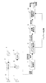
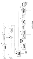
図1は、この発明の実施の形態1に係るレーダ装置の構成を示すブロック図である。図1に示すレーダ装置は、送信波を発生させる発振器1、発振器1から出力された送信波を分配する分配器2、分配器2から送信波出力の1つを入力し、空間へ送信波を放射する送信空中線3、送信波が空間中の物体により反射されることにより生じた反射波を受信することにより受信波を得る受信空中線4、受信空中線4から受信波を入力するとともに、分配器2から入力した送信波出力と混合することにより受信信号を生成する受信器5、受信器5から出力された受信信号をAD(Analog to Digital)変換することによりディジタル受信信号を生成するAD変換器6を備える。
1 is a block diagram showing a configuration of a radar apparatus according to
また、このレーダ装置は、受信信号にフーリエ変換を施すことにより受信信号のフーリエ変換を算出するフーリエ変換部7、フーリエ変換部7からの受信信号フーリエ変換を入力し、振幅が極大値となるドップラー周波数とその周波数における複素振幅値を出力するスペクトルピーク検出部8、スペクトルピーク検出部8から複素振幅を入力して蓄積するとともに、異なる送信周波数の送信波を送信して得られた複素振幅を用いて反射物体の距離を算出する距離算出部9、距離算出部9で得られた測距値の妥当性を判定し、その判定結果に応じて距離算出部9で得られた測距値とスペクトルピーク検出部8で算出されるドップラー周波数とを出力する距離判定部としての距離符号判定部10を備える。ここで、この距離符号判定部10は、距離算出部9で得られた測距値の符号の正負を判定し、正である場合にのみ、スペクトルピーク検出部8で算出されるドップラー周波数を出力するようになされている。
Further, this radar apparatus inputs a Fourier transform of the received signal by applying a Fourier transform to the received signal, and receives the Fourier transform of the received signal from the
次に、実施の形態1に係るレーダ装置の動作について説明する。発振器1は送信波を発生する。レーダ装置で良く用いられる送信周波数帯はマイクロ波帯やミリ波帯などであるが、この発明では、レーダ装置の送信周波数を特に限定するものではない。また、以後では送信波として電波を想定して説明を進めるが、電磁波の一種であるレーザ光を用いる場合、すなわちレーザレーダの場合にも同様に適用できるものである。さらに、電磁波に限らず、音波を用いたレーダ(ソーダ)にも適用可能である。
Next, the operation of the radar apparatus according to the first embodiment will be described. The
発振器1から出力される送信波の送信周波数は、複数通りに時分割で切り替えられるものとする。ここでは簡単のため、2つの送信周波数を交互に切り替えることとする。発振器1で生成された送信波は、分配器2に入力される。分配器2では、送信波を複数に分配して出力する。分配された送信波出力の1つは送信空中線003へと出力される。他の分配された送信波出力は、ローカル波として受信器5へと出力される。
It is assumed that the transmission frequency of the transmission wave output from the
送信素子である送信空中線3は、分配器2から入力された送信波を空間へ放射する。放射された送信波は、空間中に存在する反射物体で反射される。これにより生じた反射波の一部は、レーダ装置の位置に戻ってくる。レーダ位置に到来した反射波は、受信空中線4によってレーダに取り込まれる。ここでは、受信空中線4が取り込んだ反射波を受信波と呼ぶことにする。受信器5では、受信波と送信波を混合することにより、両者の差の周波数(差周波数)を持つ受信信号を生成する。差周波数は、反射物体のドップラー周波数に等しいものとなる。
The
なお、受信器5は必要に応じて増幅器を備えていても良いが、この発明のレーダ装置の方式を限定するものではないため、図1には特に明示的に示していない。
The
受信器5は、それぞれで生成した受信信号をAD変換器6へと出力する。AD変換器6は、入力した受信信号をアナログ−ディジタル変換し、得られたディジタル受信信号を生成する。
The
送信角周波数ω1による送信波が次式(1)の時系列信号として表されるとする。
![]()
![]()
受信波は、角周波数がドップラー角周波数ωDだけ送信波のものからずれるとともに、距離rに比例する位相変化が生じた次式(2)で表される。

分配器2から受信器5へ入力される送信波成分(ローカル信号)が次式(3)で表されるとする。
![]()
![]()
受信器5から出力される受信信号は、式(2)のsRF(t)と式(3)のsL(t)を乗算した後に、高調波成分を除去したものであり、次式(4)で表される。
式(4)を指数関数で表現すると次式(5)となる。
受信信号sR1(t)にフーリエ変換を施した後に、角周波数ωDの成分を抽出したものをsR+、角周波数−ωDの成分を抽出したものをsR−とすると、両者は次式(6)及び(7)で表される。
ただし、A’は抽出された信号成分の振幅を表すものであり、式(5)の信号の振幅にフーリエ変換の利得を乗じたものである。sR+およびsR−はスペクトルピーク検出部8で検出されたピークの複素振幅である。sR1+は真の信号成分、sR1−はドップラー周波数の符号あいまいさにより生じた偽の信号成分である。この偽の信号成分は、受信器にてI/Q検波を行わないためにより生じたものである。
Here, A ′ represents the amplitude of the extracted signal component, and is obtained by multiplying the amplitude of the signal of Equation (5) by the gain of Fourier transform. s R + and s R− are the complex amplitudes of the peaks detected by the
真の信号成分sR1+の位相は次式(8)で表される。
式(8)と同様にして、送信角周波数がω2の場合の、真の信号成分の位相は次式(9)で表される。
式(8)の位相と式(9)の位相差を計算すると、次式(10)を得る。
したがって、式(10)の関係を用いると、距離rを算出することができる。すなわち、2つの送信周波数を用いた観測により得られた複素振幅の位相差が反射物体の距離に比例することから、距離算出部9は次式(11)により反射物体の距離を算出する。
実際には、図1bに示す構成のレーダ装置において、受信器5はI/Q検波を行っていないため、出力される受信信号は実数信号である。そのため、ドップラースペクトルの振幅はドップラー周波数0を中心に対称となり、ドップラー周波数の正負にあいまいさが生じた状態となっている。すなわち、正しくは真の信号成分sR+を用いるべきところを、偽の信号成分sR−を用いてしまう可能性がある。
Actually, in the radar apparatus having the configuration shown in FIG. 1B, the
例えば、真のドップラー周波数が負である場合に、誤って正のドップラー周波数成分を抽出した場合、抽出される成分は式(7)で表されるsR1−である。同様に、送信角周波数ω2を用いた観測によりsR2−を得て、sR1−とsR2−の位相差を算出したΔωR−は次式(12)で表される。
式(12)のΔφR−に式(11)と同様の距離算出処理を適用すると、測距値r’は次式(13)となる。
この式から分かるように、誤った符号のドップラー周波数成分を用いて距離算出を行った場合、測距値は負の値となる。よって、距離計測値が負となる場合は、ドップラー周波数の符号が誤っているスペクトルピークを検出したと判断することができる。 As can be seen from this equation, when the distance calculation is performed using the Doppler frequency component of the wrong sign, the distance measurement value is a negative value. Therefore, when the distance measurement value is negative, it can be determined that a spectrum peak in which the sign of the Doppler frequency is incorrect is detected.
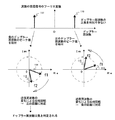
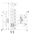
図2は、以上の説明を模式的に説明したものである。この図2では、ドップラー周波数の絶対値が同じで符号が異なる2つのドップラースペクトルのピーク110と111が得られている状況を想定している。ピーク110のドップラー周波数について、送信周波数f1を用いたときに得られた複素振幅が112、送信周波数f2を用いたときに得られた複素振幅が113であるとする。また、ピーク111のドップラー周波数について、送信周波数f1を用いたときに得られた複素振幅が114、送信周波数f2を用いたときに得られた複素振幅が115であるとする。
FIG. 2 schematically illustrates the above description. In FIG. 2, it is assumed that two Doppler spectrum peaks 110 and 111 having the same absolute value of the Doppler frequency but different signs are obtained. As for the Doppler frequency of the
ピーク110を選択した場合、式(10)で算出される位相差は正となるため、式(11)で算出される距離は負の値となる。すなわち、正のドップラー周波数を仮定すると負の距離が算出されることになる。それに対して、ピーク111を選択した場合、式(10)で算出される位相差は負となるため、式(11)で算出される距離は正の値となる。すなわち、負のドップラー周波数を仮定すると正の距離が算出されることになる。以上から、図2の状況ではドップラー周波数は負が正しいと判定することができる。
When the
以上の特性から、ピーク検出を正のドップラー周波数と負のドップラー周波数の両方で行い、距離算出を行った結果が正になる場合のみについて、測距値とドップラー周波数を出力するようにすれば、正しいドップラー周波数が出力されることになる。 From the above characteristics, if the peak detection is performed at both the positive Doppler frequency and the negative Doppler frequency and the distance calculation result is positive only, the distance measurement value and the Doppler frequency are output. The correct Doppler frequency will be output.
なお、ΔφR+は位相の値であるため、あいまいさなく算出することができる区間長は2πである。本実施の形態1のレーダ装置においては、2πの区間長を−π〜πで表現するとき、−π〜0を正の距離に、0〜πを負の距離に割り当てるようにすれば良い。想定される最大の距離がrmaxの場合、
また、ここでは、送信周波数の数を2つとして、2周波での位相差から距離を求めるものであった。この場合、受信信号sR+に含まれる目標数は1つであることを想定した処理となる。受信信号sR+に含まれる目標数が複数想定される場合には、送信周波数の数を3つ以上とした距離算出方式を用いればよい。例えば、非特許文献3のように、3つ以上の送信周波数で観測した場合に、送信周波数方向に信号列を作り、この信号列にスペクトル解析(例えばMUSIC処理)を行えば、複数目標に対して距離算出処理を行うことが可能になる。
Further, here, the number of transmission frequencies is two, and the distance is obtained from the phase difference at the two frequencies. In this case, the processing assumes that the target number included in the received signal s R + is one. When a plurality of target numbers included in the received signal s R + are assumed, a distance calculation method in which the number of transmission frequencies is three or more may be used. For example, as in
(非特許文献3)稲葉敬之, “多周波ステップICWレーダによる多目標分離法,” 電子情報通信学会論文誌 B Vol.J89-B No.3 pp.373-383, 2006. (Non-patent document 3) Inaba Noriyuki, “Multi-target separation method by multi-frequency step ICW radar,” IEICE Transactions B Vol.J89-B No.3 pp.373-383, 2006.
なお、スペクトルピークの検出を行う方法として、スペクトルの極大値を検出する方法を以上では説明した。信号成分が線スペクトルとみなせる場合には、このような簡易な方法でも問題は生じない。しかし、目標の速度がゆらぎを持っている場合や、レーダ装置のハードウェアの不安定である場合などには、スペクトルピークは幅を持つようになる。このようなスペクトルに受信機雑音が重畳すると、1つのスペクトルピーク内に複数の細かな極大値が現れる可能性がある。このような場合は、例えば非特許文献4に紹介されているようなモーメント法などの手法を用いれば、幅のあるスペクトルピークの中心周波数を適切に算出することが可能となる。 The method for detecting the maximum value of the spectrum has been described above as the method for detecting the spectrum peak. When the signal component can be regarded as a line spectrum, such a simple method does not cause a problem. However, when the target speed fluctuates or the hardware of the radar apparatus is unstable, the spectrum peak has a width. When receiver noise is superimposed on such a spectrum, a plurality of fine local maximum values may appear within one spectrum peak. In such a case, for example, if a method such as the moment method introduced in Non-Patent Document 4 is used, it is possible to appropriately calculate the center frequency of a broad spectrum peak.
(非特許文献4)H. Sauvageot, “3.1.2 Estimators of Spectral Moments, ” in Radar Meteorology, Artech House, 1992. (Non-Patent Document 4) H. Sauvageot, “3.1.2 Estimators of Spectral Moments,” in Radar Meteorology, Artech House, 1992.
以上のように、本実施の形態1のレーダ装置は、実数成分用の受信器のみがある場合にも、ドップラー周波数の符号を正しく計測することができるため、実数成分用の受信器と虚数成分用の受信器の2つが必要となるI/Q検波方式よりも、部品点数が少なくなり、レーダ装置が低価格になるという利点がある。 As described above, since the radar apparatus according to the first embodiment can correctly measure the sign of the Doppler frequency even when only the receiver for the real number component is present, the receiver for the real number component and the imaginary number component can be obtained. Compared to an I / Q detection method that requires two receivers, there are advantages in that the number of parts is reduced and the radar apparatus is inexpensive.
実施の形態2.
前述した実施の形態1では、ピーク検出を正のドップラー周波数と負のドップラー周波数の両方で行い、距離算出を行った結果が正になる場合のみについて、測距値とドップラー周波数を出力するようにしていた。本実施の形態2では、ピーク検出を正のドップラー周波数と負のドップラー周波数のいずれかの領域のみで行い、距離算出符号の結果によって、ドップラー周波数の符号を修正するようなレーダ装置の構成を説明する。
In the first embodiment described above, peak detection is performed at both the positive Doppler frequency and the negative Doppler frequency, and the distance measurement value and the Doppler frequency are output only when the distance calculation result is positive. It was. In the second embodiment, a configuration of a radar apparatus is described in which peak detection is performed only in one of the positive Doppler frequency and negative Doppler frequency regions, and the sign of the Doppler frequency is corrected based on the result of the distance calculation code. To do.
図3は、この発明の実施の形態2に係るレーダ装置の構成を示すブロック図である。図3に示す実施の形態2に係る構成において、図1に示す実施の形態1に係る構成と同一部分は同一符号を付してその説明は省略する。図3に示す実施の形態2においては、図1に示す実施の形態1に係る構成に対し、距離判定部として、距離符号判定部10の他に、距離符号判定部10にて測距値が負と判定された場合に、スペクトルピーク検出部8で得られたドップラー周波数の符号を反転させるドップラー周波数符号反転部11をさらに備えている。
FIG. 3 is a block diagram showing the configuration of the radar apparatus according to
すなわち、実施の形態2において、距離判定部は、距離算出部9で算出された測距値の符号の正負を判定すると共に、距離算出部9で得られた測距値を出力する距離符号判定部10と、距離符号判定部10により距離算出部9で算出された測距値の符号が負と判定された場合に、スペクトルピーク検出部8で得られるピーク複素信号値を抽出したドップラー周波数の符号を反転させて出力するドップラー周波数符号反転部11とでなる。
That is, in the second embodiment, the distance determination unit determines whether the sign of the distance measurement value calculated by the
次に、実施の形態2に係るレーダ装置の動作を説明する。発振器1にて送信波を生成してから、フーリエ変換部7でフーリエ変換を行うところまでは、前述した実施の形態1と同じで動作である。しかし、フーリエ変換部7で得られる受信信号フーリエ変換の振幅分布がドップラー周波数0を中心に対称となることから、スペクトルピーク検出部8におけるピーク検出処理は、ドップラー周波数が正の領域のみで行う。
Next, the operation of the radar apparatus according to the second embodiment will be described. The operation from the generation of the transmission wave by the
ドップラー周波数の真値が正である場合は、距離算出部9で得られる測距値は正の値、すなわち正しい値となる。逆に、ドップラー周波数の真値が負の場合は、距離算出部9で得られる測距値は負の値となる。しかし、この測距結果は符号が誤っているだけであるため、測距値としてはその絶対値を出力すれば良い。また、距離算出部9で得られた測距値が負であるということは、検出したドップラー周波数の符号が逆であったことを意味する。しかし、ドップラー周波数の絶対値は正しい値である。そこで、ドップラー周波数符号反転部11では、距離符号判定部10で距離符号の正負を入力し、負であった場合に、スペクトルピーク検出部8から入力したドップラー周波数の符号を負へ反転させた後に、ドップラー周波数を出力する。逆に、距離符号が正であった場合は、正しいドップラー周波数が得られることになるため、スペクトルピーク検出部8から入力したドップラー周波数をそのまま出力する。
When the true value of the Doppler frequency is positive, the distance measurement value obtained by the
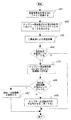
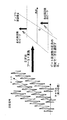
図4は、以上の動作をフローチャートで表したものである。ステップs001では、フーリエ変換部7にて受信信号にフーリエ変換を施す。ステップs002では、スペクトルピーク検出部8にてスペクトルピークの検出を行う。ただし、ドップラー周波数が正の周波数区間のみを処理対象とする。ステップs003では、距離算出部9にて式(11)を用い二周波観測の結果を用いて距離算出(測距処理)を行う。ステップs004では、ステップs003における測距値の正負を距離符号判定部10にて判定し、負であればステップs005に移る。ステップs005では、測距結果の符号を反転させる、すなわち正にする。ステップs006では、ドップラー周波数符号反転部11にてドップラー周波数の符号を反転する。
FIG. 4 is a flowchart showing the above operation. In step s001, the
以上のように、本実施の形態2では、スペクトルピーク検出の対象となるドップラー周波数の区間が半分になるため、実施の形態1の効果に加えて、演算量が少なくて済むという効果がある。 As described above, according to the second embodiment, since the Doppler frequency section that is the target of spectrum peak detection is halved, in addition to the effects of the first embodiment, there is an effect that the calculation amount is small.
実施の形態3.
前述した実施の形態1では、送信波として連続波を用いる場合に適用可能なレーダ装置の構成例を示したが、次に送信波にパルス変調を施したレーダ装置の実施の形態を示す。
In the first embodiment described above, a configuration example of a radar apparatus that can be applied when a continuous wave is used as a transmission wave has been described. Next, an embodiment of a radar apparatus that applies pulse modulation to a transmission wave will be described.
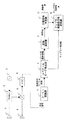
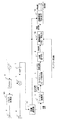
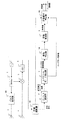
図5は、この発明の実施の形態3に係るレーダ装置の構成を示すブロック図である。図5に示す実施の形態3に係る構成において、図1に示す実施の形態1に係る構成と同一部分は同一符号を付してその説明は省略する。図5に示す実施の形態3においては、図1に示す実施の形態1に係る構成に対し、発振器1が出力した送信波にパルス変調を施すパルス変調部101と、AD変換器6で得られたディジタル受信信号のうち、一定の送受信時間差でサンプルされたもののみを抽出する、つまり送受信時刻差が同じものを選択することにより、特定の距離で反射された受信波に対応する受信信号のみを出力するとともに、送受信時刻差に対応する距離概算値を出力する距離選択部102とをさらに備えると共に、距離判定部として、距離算出部9で算出された測距値と、距離選択部102で選択対象とした距離概算値とを比較し、その比較差が所定値以下の場合のみに測距値とドップラー周波数を出力する距離範囲判定部103を備えている。
FIG. 5 is a block diagram showing the configuration of the radar apparatus according to
次に、実施の形態3に係るレーダ装置の動作を説明する。発振器1は、連続波の送信波を発生する。パルス変調部101は、この送信波にパルス変調を施す。発振器1から出力される送信波の送信周波数は、複数通りに時分割で切り替えられるものとする。ここでは簡単のため、2つの送信周波数を交互に切り替えることとする。
Next, the operation of the radar apparatus according to
発振器1で生成された送信波は、分配器2に入力される。分配器2では、送信波を複数に分配して出力する。分配された送信波出力の1つはローカル波として受信器5へと出力される。他の分配された送信波出力は、パルス変調部101にてパルス変調が施された後、送信空中線3から空間へと放射される。放射された送信波は、空間中に存在する反射物体で反射される。これにより生じた反射波の一部は、レーダ装置の位置に戻ってくる。レーダ位置に到来した反射波は、受信空中線4によって受信波としてレーダに取り込まれる。
The transmission wave generated by the
なお、本実施の形態3では、送信波にパルス変調を施しているため、送信波の放射と受信波の取り込みは異なる時間に行われる。よって、1つの空中線を時分割で使用することにより、送信空中線と受信空中線を1つの空中線で実現するような構成としても良い。 In the third embodiment, since the transmission wave is subjected to pulse modulation, the transmission wave is radiated and the reception wave is taken in at different times. Therefore, it is good also as a structure which implement | achieves a transmission antenna and a receiving antenna by one antenna by using one antenna in a time division.
受信器5では、受信波と送信波を混合することにより、両者の差の周波数(差周波数)を持つ受信信号を生成する。差周波数は反射物体のドップラー周波数に等しいものとなる。受信器5は、それぞれで生成した受信信号をAD変換器6へと出力する。AD変換器6は、入力した受信信号をアナログ−ディジタル変換し、得られたディジタル受信信号を生成する。
The
本実施の形態3においては、送信波にはパルス変調が施されている。そのため、送信と受信の時刻差、すなわち受信信号の遅延時間は反射物体の距離に比例するものとなる。したがって、パルス状に得られる受信信号(受信パルス)の遅延時間から、反射物体の距離を得ることができる。AD変換器6のサンプル周期をパルス幅と同程度に設定してやれば、パルス幅で決まる距離分解能毎に分離された受信信号を得ることができる。
In the third embodiment, the transmission wave is subjected to pulse modulation. Therefore, the time difference between transmission and reception, that is, the delay time of the received signal is proportional to the distance of the reflecting object. Therefore, the distance of the reflecting object can be obtained from the delay time of the reception signal (reception pulse) obtained in a pulse shape. If the sample period of the
距離選択部102では、AD変換器6でサンプルされたディジタル受信信号のうち、注目する距離に対応する遅延時間に得られたもののみを選択する。これにより、パルス幅で決まるある距離区間内に存在する反射物体に対応する受信信号のみが選択されることになる。選択する距離区間を変更し、その都度後段の処理を行えば、任意の距離区間の信号処理を行うことが可能である。選択された受信信号はフーリエ変換部7へと出力される。また、設定した距離区間は距離範囲判定部103へと出力される。
The
フーリエ変換部7では、距離選択部102で選択された受信信号に対してフーリエ変換を施し、受信信号フーリエ変換を算出する。さらに、スペクトルピーク検出部8で受信信号フーリエ変換の振幅が極大値となるドップラー周波数の複素振幅を抽出し、距離算出部9にて距離算出を行うことは、前述した実施の形態1の動作と同じである。ただし、距離算出に用いる受信信号が、距離選択部で設定した距離区間(測距対象区間)のみに対応するものであることが、実施の形態1と異なる。
The
距離算出部9における距離算出は、複数の送信周波数の観測で得られた複素振幅の位相差から求める。位相差は距離に比例する。しかし、あいまいさなく計測できる位相差は区間長2πの区間内のみである。前述した実施の形態1では、−πから0の区間を正の距離、0からπの区間を負の距離に割り当てることにより、負の距離が得られた場合にドップラー周波数の符号が真値と異なっていたと判定するようにしていた。前述した実施の形態1では、式(14)の条件が満たされる状況を前提としているため、位相差πに対応する距離よりも長い距離に目標は存在しないと考えてよかった。
The distance calculation in the
しかし、例えば位相差が−1.5πに対応する距離に位置する反射物体からの反射波を受信しうる場合には、0.5πの位相差と区別がつかないため、距離の符号だけでは、ドップラー周波数の符号の真偽を判定することはできない。 However, for example, when a reflected wave from a reflecting object located at a distance corresponding to a phase difference of −1.5π can be received, it cannot be distinguished from a phase difference of 0.5π. The authenticity of the sign of the Doppler frequency cannot be determined.
本実施の形態3では、送信波にパルス変調を施しているため、前述したように距離選択部102において、抽出する受信信号の距離区間を制限することができる。よって、距離選択部102における距離区間設定と、距離算出部9による測距結果を比較することにより、測距値の妥当性を判定することができる。
In
すなわち、距離範囲判定部103では、次のようにして測距値の妥当性を判定し、ドップラー周波数の符号を確定するように動作する。距離算出部9では、ドップラー周波数が正の場合と負の場合の2通りについて、測距結果を得ることができるが、距離範囲判定部103では、このうち、距離選択部102において設定した距離区間内に測距結果が得られた方が、正しいドップラー周波数成分を用いて距離算出したと判定することができる。そこで、正しい測距結果を得た場合のみについて、測距値とドップラー周波数を出力するようにする。
That is, the distance
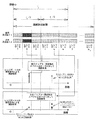
図6は、以上の原理を模式図で表したものである。この図6で想定するレーダ装置では、位相差0から−πをレンジゲート1から3の区間に割り当て(区間123)、位相差−πから−2πをレンジゲート4から6の区間に割り当てられている(区間124)。
FIG. 6 schematically shows the above principle. In the radar apparatus assumed in FIG. 6, the phase difference 0 to −π is assigned to the section of the
送信周波数f1および送信周波数f2において、レンジゲート2にてドップラースペクトルのピークが検出されたとする。ドップラースペクトルは正負のドップラー周波数で対称な形状となるが、正のドップラー周波数の区間にてピーク検出を行ったとする。送信周波数f1と送信周波数f2の双方の場合のピークの複素振幅を抽出し、式(11)と同様の処理で得られる測距値が、図6の121のような距離に得られた場合は、測距対象区間となっているレンジゲート2に測距値が得られていることから、測距結果が正しいと判定することができる。すなわち、検出されたレンジゲート内に測距結果が得られた場合、ドップラー周波数の符号はそのまま、測距値もそのままである。
It is assumed that the Doppler spectrum peak is detected by the
それに対して、測距結果が120に得られた場合、測距結果は測距対象区間であるレンジゲート2から外れているため、誤った測距結果となっていると判定することができる。正しい測距結果は、負のドップラー周波数区間で得られたピーク検出により得られた複素振幅値を用いた処理により得られるため、誤った測距結果は廃棄すれば良い。すなわち、検出されたレンジゲート外に測距結果が得られた場合は、ドップラー周波数の符号が誤っているとみなせる。
On the other hand, when the distance measurement result is obtained at 120, since the distance measurement result is out of the
パルス幅で決まる距離分解能Δrの区間において、距離算出部9における距離算出にあいまいさが生じない、すなわち、正のドップラー周波数成分から算出される測距値と、負のドップラー周波数成分から算出される測距値とが、同じΔrの区間内に入らないようなレーダ諸元となっていれば、ドップラー周波数の符号を判定することが可能になる。この場合、次式(15)を満たすようにΔfが設定されていれば良い。
ここで、Δfを調整することにより、位相差区間2πに割り当てる距離区間長を短く設定することができる。よって、同じ位相誤差に対応する距離誤差が小さくなるため、距離算出部9における距離算出精度を向上させることが可能になる。
Here, by adjusting Δf, the distance section length assigned to the phase difference section 2π can be set short. Therefore, since the distance error corresponding to the same phase error is reduced, the distance calculation accuracy in the
以上のように、本実施の形態3のレーダ装置によれば、受信器が実数信号のみを生成するような安価な装置構成の場合にも、目標のドップラー周波数の符号のあいまいさなく計測することが可能となる。すなわち、目標が接近しているのか、離反しているのかを正しく計測することが可能となる。 As described above, according to the radar apparatus of the third embodiment, even in the case of an inexpensive apparatus configuration in which the receiver generates only a real signal, measurement is performed without ambiguity in the sign of the target Doppler frequency. Is possible. That is, it is possible to correctly measure whether the target is approaching or moving away.
実施の形態4.
前述した実施の形態3において、図6に示す符号121と120に対応する距離結果r1とr2は距離区間raの中心に対して対称な位置関係のところに現れる。したがって、誤った符号のドップラー周波数の信号成分で測距した場合にも、この対称性を用いて測距結果を補正することが可能である。このような補正を行う実施の形態を示す。
Embodiment 4 FIG.
In the third embodiment described above, the distance results r1 and r2 corresponding to the
図7は、この発明の実施の形態4に係るレーダ装置の構成を示すブロック図である。図7に示す実施の形態4に係る構成において、図5に示す実施の形態3に係る構成と同一部分は同一符号を付してその説明は省略する。図7に示す実施の形態4においては、図5に示す実施の形態3に係る構成に対し、距離判定部として、距離範囲判定部103の代わりに、距離選択部102で得られた距離概算値と距離算出部9で算出された測距値を比較し、その比較差が所定値以上の場合に(両値が離れている場合に)、ドップラー周波数の符号が反転していたと仮定して、測距値を補正して測距補正値を出力する距離判定補正部104と、距離判定補正部104で得られた測距補正値と距離概算値とを比較し、その比較差が所定値以下の場合(両値が近い場合)にのみ、測距補正値と、ドップラー周波数としてドップラー周波数を反転させた符号反転ドップラー周波数とを出力する距離範囲再判定部105とを備える。
FIG. 7 is a block diagram showing a configuration of a radar apparatus according to Embodiment 4 of the present invention. In the configuration according to Embodiment 4 shown in FIG. 7, the same parts as those in the configuration according to
距離範囲判定・補正部104では、まず、はじめに図5の距離範囲判定部103と同様に、測距値が測距対象区間の中に入っているかどうかを確認する。もし区間内に入っていれば、そのまま測距値とドップラー周波数を出力する。逆に、区間内に入っていない場合は、ドップラー周波数の符号が誤っていたと仮定し、測距値を補正する。すなわち、0から−2πの範囲で算出された位相差に補正処理を行った後に、補正後の測距値を算出する。補正前後の位相差の値は、−πに関して対称に位置する。よって、補正前の位相差を−2πから引いた値を補正後の位相差とし、この値を用いて測距値を算出すればよい。これを測距値による表現で説明すると、例えば図6の例では、レンジゲート3とレンジゲート4の境界の距離について対称な位置に測距値を移動させることが、距離を補正する処理となる。
First, the distance range determination /
補正した測距値に対して、距離範囲再判定部105にて測距対象区間に含まれるか否かの判定が行われる。測距値が測距対象区間内に入れば、補正後の測距値が正しいとみなすことが適切である。しかし、測距値補正後も、測距対象区間外に測距値が得られる場合は、正しい測距値が得られないとして、測距値の出力を行わないようにする。例えば、熱雑音などの影響により誤検出されたドップラースペクトルのピークを用いて測距を行った場合に、このような正しい測距値が得られない状況が発生しうる。
The distance
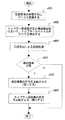
図8は、本実施の形態4のレーダ装置の動作手順を表すフローチャートである。ステップs101では、フーリエ変換部7にて受信信号にフーリエ変換を施す。ステップs102では、スペクトルピーク検出部8にてスペクトルピークの検出を行う。ただし、ドップラー周波数が正の周波数区間のみを処理対象とする。ステップ103では、距離算出部9にて式(11)を用いて二周波観測の結果を用いて、式(11)により距離算出(測距処理)を行う。
FIG. 8 is a flowchart showing an operation procedure of the radar apparatus according to the fourth embodiment. In step s101, the
ステップs104では、ステップs103で得られた測距値を距離計測対象区間と比較する。測距値が距離計測対象区間、すなわちピークが検出されたレンジゲートの中に入っていれば、正しい測距結果が得られているとみなせるため、処理を終了する。逆に、測距値が距離計測対象区間の外に得られた場合は、ステップ105に進む。ステップs105では、ドップラー周波数の符号に誤りがあったと仮定して、距離範囲判定・補正部104にて測距値の補正を行う。
In step s104, the distance measurement value obtained in step s103 is compared with the distance measurement target section. If the distance measurement value is within the distance measurement target section, that is, the range gate where the peak is detected, it can be considered that a correct distance measurement result has been obtained, and thus the process ends. On the other hand, if the distance measurement value is obtained outside the distance measurement target section, the process proceeds to step 105. In step s105, it is assumed that there is an error in the sign of the Doppler frequency, and the distance value determination /
ステップs106では、補正後の測距値と距離設定部102の距離設定区間とを比較し、比較差が所定値以下であれば、ステップs108へと進み、そうでなければステップs107へと進む。ステップs107では、補正後の測距値も誤りであるとみなして、検出・測距結果を削除する。ステップs108では、補正後の測距値が正しいとみなして、ドップラー周波数の符号を反転させる。
In step s106, the corrected distance measurement value is compared with the distance setting section of the
以上のように、本実施の形態4によれば、実施の形態3と同様に、パルス変調を行うレーダ装置において距離精度が向上される効果が得られる。さらに、ドップラー周波数の符号を誤った場合の測距値を補正するようにしているため、スペクトルピーク検出の処理対象とするドップラー周波数区間を正または負のいずれかの周波数区間に制限することができるため、信号処理演算量を低減することができる効果が得られる。 As described above, according to the fourth embodiment, as in the third embodiment, the effect of improving the distance accuracy can be obtained in the radar device that performs pulse modulation. Furthermore, since the ranging value when the sign of the Doppler frequency is wrong is corrected, the Doppler frequency section to be processed for spectrum peak detection can be limited to either a positive or negative frequency section. Therefore, an effect that the amount of signal processing calculation can be reduced is obtained.
実施の形態5.
前述した実施の形態3または4では、パルス変調部101の動作が理想的である、すなわち送信波を切っている状態において、送信波がほとんど出力されないことを想定したものであった。実際には、パルス変調部101の性能上の制約から、出力をオフにしている時間にも、送信波が弱い電力レベルで漏れることが一般的である。この送信波漏れの電力レベルが無視できないぐらいに大きい場合にも適用可能な実施の形態をここで示す。
In the above-described third or fourth embodiment, it is assumed that the operation of the
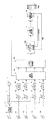
図9は、この発明の実施の形態5に係るレーダ装置の構成を示すブロック図である。図9に示す実施の形態5に係る構成において、図5に示す実施の形態3に係る構成と同一部分は同一符号を付してその説明は省略する。図9に示す実施の形態5においては、図5に示す実施の形態3に係る構成に対し、スペクトルピーク検出部8と距離算出部9との間に、異なる送受信時刻差でサンプルされた受信信号サンプルから得られた受信信号フーリエ変換において、同一のドップラー周波数で複数のピーク複素信号値が得られた場合に、最大の振幅値が得られた送受信時刻差の振幅値とその他の振幅値との割合を比較し、その割合が所定の基準より小さな振幅値が得られた送受信時刻差のピーク複素信号値は削除する振幅判定部106が付加されている。
FIG. 9 is a block diagram showing a configuration of a radar apparatus according to
つまり、本実施の形態5のレーダ装置では、パルス変調部101において、送信オフを指示している時間にも、弱い電力レベルで送信波が出力されている。そこで、異なる送受信時刻差でサンプルされた受信信号サンプルから得られた受信信号フーリエ変換において、同一のドップラー周波数でピーク複素信号値が得られた場合に、最大の振幅値が得られた送受信時刻差の振幅値と比較し、所定の基準より小さな振幅値が得られた送受信時刻差のピーク複素信号値は削除するようにしている。
That is, in the radar apparatus according to the fifth embodiment, the
図10は、本実施の形態5のレーダ装置の原理を説明する図である。実施の形態3にて説明した図6と類似の図となっているが、パルス変調部101の送信オフが完全でないことから、レンジゲート2以外においても、信号が受信される状況を表している。パルス変調部101の送信オフが完全であれば、距離選択部102においてレンジゲート2を選択した場合のみ、受信信号が検出されるが、本実施の形態5のレーダ装置では、その他のレンジゲートでも受信信号が検出される。
FIG. 10 is a diagram for explaining the principle of the radar apparatus according to the fifth embodiment. Although it is a figure similar to FIG. 6 demonstrated in
レンジゲート5で検出された受信信号を用いて距離算出部9による距離算出を行うと、レンジゲート2の区間内とレンジゲート5の区間内に測距値が得られる。正しい測距結果はレンジゲート2の区間に得られた測距値であるが、レンジゲート5でも受信信号が検出されてしまうために、レンジゲート5の区間内に得られた測距値が正しいと判定されてしまう。その結果、誤った測距結果が出力されるとともに、そのドップラー周波数の符号も誤ったものが出力される。
When the
しかし、距離選択部102でレンジゲート2を選択した場合の検出結果を見れば、距離選択部102でレンジゲート5を選択した場合に誤った測距結果が得られる可能性があることは容易に判断できる。すなわち、距離選択部102でレンジゲート2を選択した場合の距離算出処理において、レンジゲート5の区間内に偽の測距値が得られるが、同じ測距値はレンジゲート5を距離選択部102で選択した場合にも、同じように発生する。ただし、レンジゲート5を距離選択部102で選択した場合の受信信号の振幅は、レンジゲート2を選択した場合よりも十分に電力値は小さい。なぜなら、送信オフが不完全ではあるものの、送信オフとしている時間の送信漏れの電力は、送信オンにしているときに送信される電力よりも明らかに小さいためである。
However, when looking at the detection result when the
そこで、レンジゲート5を選択した場合に、レンジゲート5の区間内で測距値が得られたときに、他のレンジゲートを選択した場合に偽の測距値として、同じ測距値が得られていないかを調べる。もし同じ測距値が別のレンジゲートを選択したときに得られていれば、その測距値を算出したときの受信信号の振幅を比較する。もし、別のレンジゲートを選択したときの受信信号振幅の方が大きければ、レンジゲート5による測距値は偽の測距値である可能性があることから、その結果を除去するようにすれば良い。
Therefore, when the
すなわち、図10において、レンジゲート2で負のドップラー周波数、レンジゲート5で正のドップラー周波数が得られ、どちらも整合する結果となるが、このような場合の対策として、複数のレンジゲートで同一ドップラー周波数のスペクトルピークが得られた場合、振幅の大きいスペクトルピークのみを採用し、測距処理を行う。
That is, in FIG. 10, a negative Doppler frequency is obtained by the
なお、図9に示す構成は、図5に示す実施の形態3に係る構成に対し、スペクトルピーク検出部8と距離算出部9との間に、振幅判定部106を付加したものであるが、図7に示す実施の形態4に対しても、スペクトルピーク検出部8と距離算出部9との間に、振幅判定部106を付加することで同様な実施でき、同様な効果を奏する。
The configuration shown in FIG. 9 is obtained by adding an
本実施の形態5によれば、パルス変調部101の性能が十分でない場合にも正しくドップラー周波数の符号を判定できることから、パルス変調部101として低価格な部品を使用することができる利点がある。
According to the fifth embodiment, since the sign of the Doppler frequency can be correctly determined even when the performance of the
実施の形態6.
以上の実施の形態1−5では、受信空中線4が1つだけの構成であったが、ここでは、複数の受信素子により受信空中線が構成され、受信ビームを信号処理で合成するような実施の形態を示す。本実施の形態6では、ドップラー周波数の符号に加えて、角度計測の符号あいまいさも解消するものとなっている。
In the above Embodiment 1-5, the configuration has only one reception antenna 4. However, here, a reception antenna is configured by a plurality of reception elements, and a reception beam is synthesized by signal processing. The form is shown. In the sixth embodiment, in addition to the sign of Doppler frequency, the sign ambiguity of angle measurement is also eliminated.
図11は、この発明の実施の形態6に係るレーダ装置の構成を示すブロック図である。図11に示す実施の形態6に係る構成において、図5に示す実施の形態3に係る構成と同一部分は同一符号を付してその説明は省略する。図11に示す実施の形態6においては、図5に示す実施の形態3に係る構成に対し、受信空中線は受信素子4a〜4dで構成され、各受信素子に対して、受信器5a〜5dが接続されていて、複数チャネル備えられている。また、これらの受信器にAD変換器6a〜6dが接続されている。
FIG. 11 is a block diagram showing a configuration of a radar apparatus according to
また、フーリエ変換部は、時間方向と受信素子方向の2次元で定義される受信信号に対して2次元フーリエ変換を行う2次元フーリエ変換部107でなり、距離選択部102から選択出力された複数の受信器で生成される実数受信信号に対して素子方向にフーリエ変換を施すことで角度方向の信号分布を得るようになされている。また、スペクトルピーク検出部は、受信信号の2次元フーリエ変換に対して、振幅が極大となる点を検出して、その複素振幅、ドップラー周波数、角度を出力する2次元スペクトルピーク検出部108でなる。
The Fourier transform unit includes a two-dimensional
さらに、距離判定部としては、距離選択部10で得られた距離概算値と距離算出部9で得られた測距値とを比較し、その比較差が所定値以下の場合にのみ、距離算出部9で算出された測距値と、2次元スペクトルピーク検出部108で算出されたドップラー周波数及び角度とを出力する距離範囲判定部103でなる。
Further, the distance determination unit compares the approximate distance value obtained by the
発振器1で送信波を生成して、距離選択部102で距離を選択するところまでは、前述した実施の形態とほぼ同じである。ただし、受信素子からAD変換器が複数個備わっており、これにより複数チャネルの受信系が構成されている。
The steps up to generating a transmission wave by the
複数の受信素子4a〜4dは素子位置を少しずつずらして配置されている。その結果、受信波の到来角によって決まる位相差が受信素子間で生じる。この位相差の情報を用いた信号処理により、到来波の角度を知ることができる。すなわち、受信ビームを信号処理的に合成することができる。このような技術はDBF(Digital Beam Forming)と呼ばれる従来から良く知られた技術である。具体的には、素子方向にフーリエ変換を行うと、その結果が角度方向の受信信号分布となる。 The plurality of receiving elements 4a to 4d are arranged with their element positions shifted little by little. As a result, a phase difference determined by the arrival angle of the received wave is generated between the receiving elements. The angle of the incoming wave can be known by signal processing using this phase difference information. That is, the received beam can be combined in a signal processing manner. Such a technique is a conventionally well-known technique called DBF (Digital Beam Forming). Specifically, when Fourier transform is performed in the element direction, the result is a received signal distribution in the angular direction.
図11の構成例の場合、距離選択部102によって全てのチャネルで同じ距離設定区間のデータが抽出され、その後、2次元フーリエ変換部107にて2次元フーリエ変換が適用されている。2次元フーリエ変換は時間軸方向と素子方向のフーリエ変換を同時に行うものである。ただし、各チャネルの受信信号は実数信号であることから、前述した実施の形態と同様に、フーリエ変換の結果に符号のあいまいさが生じる。具体的には、前述した実施の形態と同様にドップラー周波数の符号あいまいさが出ると同時に、角度の符号あいまいさが生じる。図12は、符号あいまいさの生じ方を説明したものである。この図12の左側に示したように、ドップラー周波数と角度で表される2次元空間上において、1つの反射物体に対応して、原点を中心に対称な位置に2つのスペクトルピークが得られる。
In the configuration example of FIG. 11, data of the same distance setting section is extracted for all channels by the
2次元スペクトルピーク検出部108では、2次元フーリエ変換のピークを検出し、その複素振幅を抽出する。距離算出部9では、同じピーク位置(ドップラー周波数と角度)で得られた複素振幅値を用いて、前述した実施の形態と同様の測距処理を行う。距離範囲判定部103では、距離算出部9で得られた測距値が、距離選択部102で設定した距離計測対象区間に入っているか否かを確認する。もし区間内であれば、そのまま測距値とドップラー周波数を出力し、逆に区間外であれば、誤ったドップラー周波数の符号を持つピークを用いて測距したと判断し、測距結果を廃棄する。
The two-dimensional spectrum
この実施の形態6は、図11に示す構成の他、図7や図8で説明した実施の形態4のように、ドップラー周波数の符号が誤っていたと仮定して測距結果を補正し、距離範囲を再判定したのちに、補正した測距結果を出力するような構成とすることも可能である。さらに、図9や図10で説明した実施の形態5のような、パルス化が不完全な場合の処理に適用するようにしても良い。 In the sixth embodiment, in addition to the configuration shown in FIG. 11, the distance measurement result is corrected by assuming that the sign of the Doppler frequency is incorrect, as in the fourth embodiment described with reference to FIGS. 7 and 8. A configuration in which the corrected distance measurement result is output after the range is determined again is also possible. Furthermore, the present invention may be applied to processing when pulsing is incomplete as in the fifth embodiment described with reference to FIGS.
また、本実施の形態6では、送信波をパルス化した場合について、角度の符号判定を加えた構成を説明したが、図1に示す実施の形態1のように送信波をパルス化しない場合についても、同様に角度の符号判定を加えた構成とすることができる。 Further, in the sixth embodiment, the configuration in which the sign determination of the angle is added is described for the case where the transmission wave is pulsed, but the case where the transmission wave is not pulsed as in the first embodiment shown in FIG. Similarly, an angle code determination can be added.
すなわち、フーリエ変換部を、複数の受信器から生成される実数受信信号に対し、時間方向と素子方向に2次元フーリエ変換を施す2次元フーリエ変換部107で構成し、スペクトルピーク検出部を、2次元フーリエ変換部からのフーリエ変換結果を入力し、振幅が極大となるピーク複素信号値を抽出する2次元スペクトルピーク検出部108で構成し、距離判定部により、距離算出部からの測距値の妥当性の判定結果に応じて距離算出部で算出された測距値とスペクトルピーク検出部で検出されるドップラー周波数及び角度を出力するよう構成すれば、この実施の形態6を、実施の形態1−5のいずれの場合にも適用できる。
That is, the Fourier transform unit includes a two-dimensional
また、以上の説明では、ドップラー周波数と角度の2つの符号を確定させるような構成であったが、角度のみの符号を確定させるような構成のレーダ装置とすることも可能である。この場合、フーリエ変換は受信チャネル方向の1次元のみで行うことになる。 In the above description, the two signs of the Doppler frequency and the angle are determined. However, the radar apparatus may be configured to determine the sign of only the angle. In this case, the Fourier transform is performed only in one dimension in the direction of the reception channel.
すなわち、実施の形態1−5において、図11と同様に、複数の受信空中線4a〜4dと、複数の受信器5a〜5dとを有する複数チャネルの受信系を構成し、フーリエ変換部7により、複数の受信器5a〜5dから生成される実数受信信号に対し素子方向にフーリエ変換を施し、スペクトルピーク検出部8により、フーリエ変換結果を入力し、振幅が極大となる角度点のピーク複素信号値を抽出するようにすれば、距離判定部により、ドップラー周波数に代えて角度を測距値と共に出力することができ、実施の形態1−5と同様な効果を得ることができる。
That is, in Embodiment 1-5, similarly to FIG. 11, a multi-channel reception system including a plurality of reception antennas 4 a to 4 d and a plurality of receivers 5 a to 5 d is configured. The real number reception signals generated from the plurality of receivers 5a to 5d are subjected to Fourier transform in the element direction, the Fourier transform result is input by the
以上のように、本実施の形態6によれば、前述した実施の形態の効果に加えて、角度の符号についても正しいものを出力できるという利点を有する。 As described above, according to the sixth embodiment, in addition to the effects of the above-described embodiment, there is an advantage that a correct angle sign can be output.
1 発振器、2 分配器、3 送信空中線、4,4a〜4d 受信空中線、5,5a〜5d 受信器、6,6a〜6d AD変換器、7 フーリエ変換部、8 スペクトルピーク検出部、9 距離算出部、10 距離符号判定部(距離判定部)、11 ドップラー周波数符号反転部(距離判定部)、101 パルス変調部、102 距離選択部、103 距離範囲判定部(距離判定部)、104 距離判定補正部(距離判定部)、105 距離範囲再判定部(距離判定部)、106 振幅判定部、107 2次元フーリエ変換部、108 2次元スペクトルピーク検出部。
DESCRIPTION OF
Claims (7)
複数の送信周波数の波動を発生する発振器と、
前記発振器で発生された波動を空間に放射する送信空中線と、
到来した波動を受信する受信空中線と、
前記受信空中線で受信された受信波動を検波することにより、実数受信信号を生成する受信器と、
前記受信器から生成される実数受信信号に対し時間方向にフーリエ変換するフーリエ変換部と、
前記フーリエ変換部からのフーリエ変換結果を入力し、振幅が極大となるドップラー周波数点のピーク複素信号値及び前記ピーク複素信号値の複素振幅を抽出するスペクトルピーク検出部と、
複数の送信周波数を用いて得られる前記スペクトルピーク検出部からの前記複素振幅を蓄積し、蓄積した前記複素振幅の位相差から反射物体の距離を算出して測距値として出力する距離算出部と、
前記距離算出部からの測距値の妥当性を判定しその判定結果に応じて前記距離算出部で算出された測距値と前記スペクトルピーク検出部で検出されるドップラー周波数とを出力する距離判定部と、
前記発振器で発生させた波動にパルス変調を施すパルス変調器と、
複数のパルス送信で得られた前記受信器からの実数受信信号のうち、送受信時刻差が同じものを選択して出力するとともに、送受信時刻差に対応する距離概算値を出力する距離選択部と
を備え、
前記送信空中線は、前記パルス変調器を介した波動を空間に放射し、
前記フーリエ変換部は、前記距離選択部から選択出力された実数受信信号にフーリエ変換を施し、
前記距離判定部は、前記距離選択部で得られた距離概算値と前記距離算出部で算出された測距値を比較し、その比較差が所定値以上の場合に、ドップラー周波数の符号が反転していたと仮定して、前記測距値を補正して測距補正値を算出する距離判定補正部と、前記距離判定補正部で算出された前記測距補正値と前記距離概算値とを比較し、その比較差が所定値以下の場合にのみ、前記距離算出部で算出された前記測距値を出力する代わりに、前記測距補正値を出力するとともに、前記スペクトルピーク検出部で検出される前記ドップラー周波数を出力する代わりに、前記ドップラー周波数を反転させた符号反転ドップラー周波数を出力する距離範囲再判定部とでなる
ことを特徴とするレーダ装置。 In a radar apparatus that radiates a wave in space, receives a wave reflected by an object existing in the space, and measures the object by performing signal processing on the received wave,
An oscillator that generates waves of multiple transmission frequencies;
A transmitting antenna that radiates the waves generated by the oscillator into space;
A receiving antenna that receives incoming waves,
A receiver that generates a real reception signal by detecting a received wave received by the reception antenna;
A Fourier transform unit for performing a Fourier transform in the time direction on the real number reception signal generated from the receiver;
A spectrum peak detection unit that inputs a Fourier transform result from the Fourier transform unit, and extracts a peak complex signal value at a Doppler frequency point at which the amplitude is maximized and a complex amplitude of the peak complex signal value ;
A distance calculation unit that accumulates the complex amplitude from the spectrum peak detection unit obtained using a plurality of transmission frequencies, calculates a distance of a reflecting object from a phase difference of the accumulated complex amplitude, and outputs the distance as a distance measurement value; ,
Distance determination for determining the validity of the distance measurement value from the distance calculation unit and outputting the distance measurement value calculated by the distance calculation unit and the Doppler frequency detected by the spectrum peak detection unit according to the determination result and parts,
A pulse modulator for performing pulse modulation on the wave generated by the oscillator;
A distance selection unit for selecting and outputting a real reception signal from the receiver obtained by a plurality of pulse transmissions with the same transmission / reception time difference, and outputting a rough distance value corresponding to the transmission / reception time difference;
With
The transmitting antenna radiates a wave through the pulse modulator to space,
The Fourier transform unit performs a Fourier transform on the real number reception signal selected and output from the distance selection unit,
The distance determination unit compares the approximate distance value obtained by the distance selection unit with the distance measurement value calculated by the distance calculation unit, and if the comparison difference is equal to or greater than a predetermined value, the sign of the Doppler frequency is inverted. A distance determination correction unit that corrects the distance measurement value to calculate a distance measurement correction value, and compares the distance measurement correction value calculated by the distance determination correction unit and the approximate distance value. However, only when the comparison difference is equal to or smaller than a predetermined value, instead of outputting the distance measurement value calculated by the distance calculation unit, the distance measurement correction value is output and the spectrum peak detection unit detects the distance measurement correction value. A radar apparatus comprising: a distance range re-determination unit that outputs a sign-inverted Doppler frequency obtained by inverting the Doppler frequency instead of outputting the Doppler frequency .
前記スペクトルピーク検出部と前記距離算出部との間に、異なる送受信時刻差でサンプルされた受信信号サンプルから得られたフーリエ変換結果において、同一のドップラー周波数で複数のピーク複素信号値が得られた場合に、最大の振幅値が得られた送受信時刻差の振幅値とその他の振幅値との割合を比較し、その割合が所定の基準より小さな振幅値が得られた送受信時刻差のピーク複素信号値は削除する振幅判定部を設けた
ことを特徴とするレーダ装置。 The radar apparatus according to claim 1 , wherein
In the Fourier transform results obtained from the received signal samples sampled at different transmission / reception time differences between the spectrum peak detecting unit and the distance calculating unit, a plurality of peak complex signal values were obtained at the same Doppler frequency. In this case, the ratio of the amplitude value of the transmission / reception time difference at which the maximum amplitude value was obtained is compared with other amplitude values, and the peak complex signal of the transmission / reception time difference at which the ratio obtained an amplitude value smaller than a predetermined reference A radar device characterized in that an amplitude determination unit for deleting values is provided.
複数の送信周波数の波動を発生する発振器と、
前記発振器で発生された波動を空間に放射する送信空中線と、
到来した波動を受信する受信空中線と、
前記受信空中線で受信された受信波動を検波することにより、実数受信信号を生成する受信器と、
前記受信器から生成される実数受信信号に対し時間方向にフーリエ変換するフーリエ変換部と、
前記フーリエ変換部からのフーリエ変換結果を入力し、振幅が極大となるドップラー周波数点のピーク複素信号値及び前記ピーク複素信号値の複素振幅を抽出するスペクトルピーク検出部と、
複数の送信周波数を用いて得られる前記スペクトルピーク検出部からの前記複素振幅を蓄積し、蓄積した前記複素振幅の位相差から反射物体の距離を算出して測距値として出力する距離算出部と、
前記距離算出部からの測距値の妥当性を判定しその判定結果に応じて前記距離算出部で算出された測距値と前記スペクトルピーク検出部で検出されるドップラー周波数とを出力する距離判定部と、
前記発振器で発生させた波動にパルス変調を施すパルス変調器と、
複数のパルス送信で得られた前記受信器からの実数受信信号のうち、送受信時刻差が同じものを選択して出力するとともに、送受信時刻差に対応する距離概算値を出力する距離選択部と
を備え、
前記送信空中線は、前記パルス変調器を介した波動を空間に放射し、
前記フーリエ変換部は、前記距離選択部から選択出力された実数受信信号にフーリエ変換を施し、
前記距離判定部は、前記距離選択部で得られた距離概算値と前記距離算出部で得られた測距値とを比較し、その比較差が所定値以下の場合にのみ、前記距離算出部で算出された測距値と前記スペクトルピーク検出部で算出されたドップラー周波数とを出力する距離範囲判定部でなり、
前記スペクトルピーク検出部と前記距離算出部との間に、異なる送受信時刻差でサンプルされた受信信号サンプルから得られたフーリエ変換結果において、同一のドップラー周波数で複数のピーク複素信号値が得られた場合に、最大の振幅値が得られた送受信時刻差の振幅値とその他の振幅値との割合を比較し、その割合が所定の基準より小さな振幅値が得られた送受信時刻差のピーク複素信号値は削除する振幅判定部を設けた
ことを特徴とするレーダ装置。 In a radar apparatus that radiates a wave in space, receives a wave reflected by an object existing in the space, and measures the object by performing signal processing on the received wave,
An oscillator that generates waves of multiple transmission frequencies;
A transmitting antenna that radiates the waves generated by the oscillator into space;
A receiving antenna that receives incoming waves,
A receiver that generates a real reception signal by detecting a received wave received by the reception antenna;
A Fourier transform unit for performing a Fourier transform in the time direction on the real number reception signal generated from the receiver;
A spectrum peak detection unit that inputs a Fourier transform result from the Fourier transform unit, and extracts a peak complex signal value at a Doppler frequency point at which the amplitude is maximized and a complex amplitude of the peak complex signal value ;
A distance calculation unit that accumulates the complex amplitude from the spectrum peak detection unit obtained using a plurality of transmission frequencies, calculates a distance of a reflecting object from a phase difference of the accumulated complex amplitude, and outputs the distance as a distance measurement value; ,
Distance determination for determining the validity of the distance measurement value from the distance calculation unit and outputting the distance measurement value calculated by the distance calculation unit and the Doppler frequency detected by the spectrum peak detection unit according to the determination result and parts,
A pulse modulator for performing pulse modulation on the wave generated by the oscillator;
A distance selection unit for selecting and outputting a real reception signal from the receiver obtained by a plurality of pulse transmissions with the same transmission / reception time difference, and outputting a rough distance value corresponding to the transmission / reception time difference;
With
The transmitting antenna radiates a wave through the pulse modulator to space,
The Fourier transform unit performs a Fourier transform on the real number reception signal selected and output from the distance selection unit,
The distance determination unit compares the distance approximate value obtained by the distance selection unit and the distance measurement value obtained by the distance calculation unit, and only when the comparison difference is a predetermined value or less, the distance calculation unit A distance range determination unit that outputs the distance measurement value calculated in step 1 and the Doppler frequency calculated by the spectrum peak detection unit,
In the Fourier transform results obtained from the received signal samples sampled at different transmission / reception time differences between the spectrum peak detecting unit and the distance calculating unit, a plurality of peak complex signal values were obtained at the same Doppler frequency. In this case, the ratio of the amplitude value of the transmission / reception time difference at which the maximum amplitude value was obtained is compared with other amplitude values, and the peak complex signal of the transmission / reception time difference at which the ratio obtained an amplitude value smaller than a predetermined reference A radar apparatus comprising an amplitude determination unit for deleting values .
複数の送信周波数の波動を発生する発振器と、
前記発振器で発生された波動を空間に放射する送信空中線と、
到来した波動を受信する複数の受信空中線と、
前記複数の受信空中線で受信された受信波動を検波することにより、実数受信信号を生成する複数の受信器と、
前記複数の受信器から生成される実数受信信号に対し、前記複数の受信器を構成する複数の受信素子の素子方向にフーリエ変換を施すフーリエ変換部と、
前記フーリエ変換部からのフーリエ変換結果を入力し、振幅が極大となる角度点のピーク複素信号値及び前記ピーク複素信号値の複素振幅を抽出するスペクトルピーク検出部と、
複数の送信周波数を用いて得られる前記スペクトルピーク検出部からの前記複素振幅を蓄積し、蓄積した前記複素振幅の位相差から反射物体の距離を算出して測距値として出力する距離算出部と、
前記距離算出部からの測距値の妥当性を判定しその判定結果に応じて前記距離算出部で算出された測距値と前記スペクトルピーク検出部で検出される角度とを出力する距離判定部と、
前記発振器で発生させた波動にパルス変調を施すパルス変調器と、
複数のパルス送信で得られた前記受信器からの実数受信信号のうち、送受信時刻差が同じものを選択して出力するとともに、送受信時刻差に対応する距離概算値を出力する距離選択部と
を備え、
前記送信空中線は、前記パルス変調器を介した波動を空間に放射し、
前記フーリエ変換部は、前記距離選択部から選択出力された実数受信信号にフーリエ変換を施し、
前記距離判定部は、前記距離選択部で得られた距離概算値と前記距離算出部で算出された測距値を比較し、その比較差が所定値以上の場合に、角度の符号が反転していたと仮定して、前記測距値を補正して測距補正値を算出する距離判定補正部と、前記距離判定補正部で算出された前記測距補正値と前記距離概算値とを比較し、その比較差が所定値以下の場合にのみ、前記距離算出部で算出された前記測距値を出力する代わりに、前記測距補正値を出力するとともに、前記スペクトルピーク検出部で検出される前記角度を出力する代わりに、前記角度を反転させた符号反転角度とを出力する距離範囲再判定部とでなる
ことを特徴とするレーダ装置。 In a radar apparatus that radiates a wave in space, receives a wave reflected by an object existing in the space, and measures the object by performing signal processing on the received wave,
An oscillator that generates waves of multiple transmission frequencies;
A transmitting antenna that radiates the waves generated by the oscillator into space;
A plurality of receiving antennas for receiving incoming waves;
A plurality of receivers for generating a real reception signal by detecting reception waves received by the plurality of reception antennas;
A Fourier transform unit that performs a Fourier transform on the element reception direction of a plurality of receiving elements constituting the plurality of receivers with respect to a real number reception signal generated from the plurality of receivers ;
A spectral peak detection unit that inputs a Fourier transform result from the Fourier transform unit, and extracts a peak complex signal value at an angle point where the amplitude is maximized and a complex amplitude of the peak complex signal value ;
A distance calculation unit that accumulates the complex amplitude from the spectrum peak detection unit obtained using a plurality of transmission frequencies, calculates a distance of a reflecting object from a phase difference of the accumulated complex amplitude, and outputs the distance as a distance measurement value; ,
A distance determination unit that determines the validity of the distance measurement value from the distance calculation unit and outputs the distance measurement value calculated by the distance calculation unit and the angle detected by the spectrum peak detection unit according to the determination result and,
A pulse modulator for performing pulse modulation on the wave generated by the oscillator;
A distance selection unit for selecting and outputting a real reception signal from the receiver obtained by a plurality of pulse transmissions with the same transmission / reception time difference, and outputting a rough distance value corresponding to the transmission / reception time difference;
With
The transmitting antenna radiates a wave through the pulse modulator to space,
The Fourier transform unit performs a Fourier transform on the real number reception signal selected and output from the distance selection unit,
The distance determination unit compares the approximate distance value obtained by the distance selection unit with the distance measurement value calculated by the distance calculation unit, and if the comparison difference is equal to or greater than a predetermined value, the sign of the angle is inverted. The distance determination correction unit that corrects the distance measurement value to calculate the distance measurement correction value, and compares the distance measurement correction value calculated by the distance determination correction unit with the approximate distance value. Only when the comparison difference is equal to or smaller than a predetermined value, instead of outputting the distance measurement value calculated by the distance calculation unit, the distance correction value is output and detected by the spectrum peak detection unit. A radar apparatus comprising: a distance range re-determination unit that outputs a sign inversion angle obtained by inverting the angle instead of outputting the angle .
前記スペクトルピーク検出部と前記距離算出部との間に、異なる送受信時刻差でサンプルされた受信信号サンプルから得られたフーリエ変換結果において、同一の角度で複数のピーク複素信号値が得られた場合に、最大の振幅値が得られた送受信時刻差の振幅値とその他の振幅値との割合を比較し、その割合が所定の基準より小さな振幅値が得られた送受信時刻差のピーク複素信号値は削除する振幅判定部を設けた
ことを特徴とするレーダ装置。 The radar apparatus according to claim 4 , wherein
When multiple peak complex signal values are obtained at the same angle in the Fourier transform results obtained from the received signal samples sampled at different transmission / reception time differences between the spectrum peak detection unit and the distance calculation unit Next, compare the ratio of the amplitude value of the transmission / reception time difference at which the maximum amplitude value was obtained with other amplitude values, and the peak complex signal value of the transmission / reception time difference at which the ratio obtained an amplitude value smaller than a predetermined reference Is provided with an amplitude determination unit to be deleted.
複数の送信周波数の波動を発生する発振器と、
前記発振器で発生された波動を空間に放射する送信空中線と、
到来した波動を受信する複数の受信空中線と、
前記複数の受信空中線で受信された受信波動を検波することにより、実数受信信号を生成する複数の受信器と、
前記複数の受信器から生成される実数受信信号に対し、前記複数の受信器を構成する複数の受信素子の素子方向にフーリエ変換を施すフーリエ変換部と、
前記フーリエ変換部からのフーリエ変換結果を入力し、振幅が極大となる角度点のピーク複素信号値及び前記ピーク複素信号値の複素振幅を抽出するスペクトルピーク検出部と、
複数の送信周波数を用いて得られる前記スペクトルピーク検出部からの前記複素振幅を蓄積し、蓄積した前記複素振幅の位相差から反射物体の距離を算出して測距値として出力する距離算出部と、
前記距離算出部からの測距値の妥当性を判定しその判定結果に応じて前記距離算出部で算出された測距値と前記スペクトルピーク検出部で検出される角度とを出力する距離判定部と、
前記発振器で発生させた波動にパルス変調を施すパルス変調器と、
複数のパルス送信で得られた前記受信器からの実数受信信号のうち、送受信時刻差が同じものを選択して出力するとともに、送受信時刻差に対応する距離概算値を出力する距離選択部と
を備え、
前記送信空中線は、前記パルス変調器を介した波動を空間に放射し、
前記フーリエ変換部は、前記距離選択部から選択出力された実数受信信号にフーリエ変換を施し、
前記距離判定部は、前記距離選択部で得られた距離概算値と前記距離算出部で得られた測距値とを比較し、その比較差が所定値以下の場合にのみ、前記距離算出部で算出された測距値と前記スペクトルピーク検出部で算出された角度とを出力する距離範囲判定部でなり、
前記スペクトルピーク検出部と前記距離算出部との間に、異なる送受信時刻差でサンプルされた受信信号サンプルから得られたフーリエ変換結果において、同一の角度で複数のピーク複素信号値が得られた場合に、最大の振幅値が得られた送受信時刻差の振幅値とその他の振幅値との割合を比較し、その割合が所定の基準より小さな振幅値が得られた送受信時刻差のピーク複素信号値は削除する振幅判定部を設けた
ことを特徴とするレーダ装置。 In a radar apparatus that radiates a wave in space, receives a wave reflected by an object existing in the space, and measures the object by performing signal processing on the received wave,
An oscillator that generates waves of multiple transmission frequencies;
A transmitting antenna that radiates the waves generated by the oscillator into space;
A plurality of receiving antennas for receiving incoming waves;
A plurality of receivers for generating a real reception signal by detecting reception waves received by the plurality of reception antennas;
A Fourier transform unit that performs a Fourier transform on the element reception direction of a plurality of receiving elements constituting the plurality of receivers with respect to a real number reception signal generated from the plurality of receivers ;
A spectral peak detection unit that inputs a Fourier transform result from the Fourier transform unit, and extracts a peak complex signal value at an angle point where the amplitude is maximized and a complex amplitude of the peak complex signal value ;
A distance calculation unit that accumulates the complex amplitude from the spectrum peak detection unit obtained using a plurality of transmission frequencies, calculates a distance of a reflecting object from a phase difference of the accumulated complex amplitude, and outputs the distance as a distance measurement value; ,
A distance determination unit that determines the validity of the distance measurement value from the distance calculation unit and outputs the distance measurement value calculated by the distance calculation unit and the angle detected by the spectrum peak detection unit according to the determination result and,
A pulse modulator for performing pulse modulation on the wave generated by the oscillator;
A distance selection unit for selecting and outputting a real reception signal from the receiver obtained by a plurality of pulse transmissions with the same transmission / reception time difference, and outputting a rough distance value corresponding to the transmission / reception time difference;
With
The transmitting antenna radiates a wave through the pulse modulator to space,
The Fourier transform unit performs a Fourier transform on the real number reception signal selected and output from the distance selection unit,
The distance determination unit compares the distance approximate value obtained by the distance selection unit and the distance measurement value obtained by the distance calculation unit, and only when the comparison difference is a predetermined value or less, the distance calculation unit A distance range determination unit that outputs the distance measurement value calculated in step 1 and the angle calculated by the spectrum peak detection unit,
When multiple peak complex signal values are obtained at the same angle in the Fourier transform results obtained from the received signal samples sampled at different transmission / reception time differences between the spectrum peak detection unit and the distance calculation unit Next, compare the ratio of the amplitude value of the transmission / reception time difference at which the maximum amplitude value was obtained with other amplitude values, and the peak complex signal value of the transmission / reception time difference at which the ratio obtained an amplitude value smaller than a predetermined reference Is provided with an amplitude determination unit to be deleted .
前記フーリエ変換部は、前記複数の受信器から生成される実数受信信号に対し、時間方向と前記素子方向に2次元フーリエ変換を施す2次元フーリエ変換部でなり、
前記スペクトルピーク検出部は、前記2次元フーリエ変換部からのフーリエ変換結果を入力し、振幅が極大となるピーク複素信号値を抽出する2次元スペクトルピーク検出部でなる
ことを特徴とするレーダ装置。 The radar apparatus according to any one of claims 4 to 6 ,
The Fourier transform unit, to a real received signal generated from the plurality of receivers, it becomes a two-dimensional Fourier transform unit for performing a two-dimensional Fourier transform in the time direction and the element direction,
The radar apparatus according to claim 1, wherein the spectrum peak detection unit is a two-dimensional spectrum peak detection unit that inputs a Fourier transform result from the two-dimensional Fourier transform unit and extracts a peak complex signal value having a maximum amplitude.
Priority Applications (3)
| Application Number | Priority Date | Filing Date | Title |
|---|---|---|---|
| JP2007156546A JP5376777B2 (en) | 2007-06-13 | 2007-06-13 | Radar equipment |
| US11/870,106 US7528768B2 (en) | 2007-06-13 | 2007-10-10 | Radar device |
| DE102007052940.8A DE102007052940B4 (en) | 2007-06-13 | 2007-11-02 | radar device |
Applications Claiming Priority (1)
| Application Number | Priority Date | Filing Date | Title |
|---|---|---|---|
| JP2007156546A JP5376777B2 (en) | 2007-06-13 | 2007-06-13 | Radar equipment |
Publications (2)
| Publication Number | Publication Date |
|---|---|
| JP2008309582A JP2008309582A (en) | 2008-12-25 |
| JP5376777B2 true JP5376777B2 (en) | 2013-12-25 |
Family
ID=39986287
Family Applications (1)
| Application Number | Title | Priority Date | Filing Date |
|---|---|---|---|
| JP2007156546A Active JP5376777B2 (en) | 2007-06-13 | 2007-06-13 | Radar equipment |
Country Status (3)
| Country | Link |
|---|---|
| US (1) | US7528768B2 (en) |
| JP (1) | JP5376777B2 (en) |
| DE (1) | DE102007052940B4 (en) |
Cited By (1)
| Publication number | Priority date | Publication date | Assignee | Title |
|---|---|---|---|---|
| WO2022220464A1 (en) * | 2020-04-14 | 2022-10-20 | Bitsensing Inc. | Dnn-based human face classificati0n |
Families Citing this family (45)
| Publication number | Priority date | Publication date | Assignee | Title |
|---|---|---|---|---|
| WO2006013615A1 (en) * | 2004-08-02 | 2006-02-09 | Mitsubishi Denki Kabushiki Kaisha | Radar apparatus |
| DE202006005643U1 (en) * | 2006-03-31 | 2006-07-06 | Faro Technologies Inc., Lake Mary | Device for three-dimensional detection of a spatial area |
| DE102006031580A1 (en) | 2006-07-03 | 2008-01-17 | Faro Technologies, Inc., Lake Mary | Method and device for the three-dimensional detection of a spatial area |
| US7791528B2 (en) * | 2008-11-24 | 2010-09-07 | Autoliv Asp, Inc. | Method and apparatus for radar signal processing |
| DE102009005745B4 (en) * | 2009-01-23 | 2011-09-01 | Ott-Jakob Spanntechnik Gmbh | Device for monitoring the position of a tool or machine element |
| DE102009010465B3 (en) | 2009-02-13 | 2010-05-27 | Faro Technologies, Inc., Lake Mary | laser scanner |
| DE102009015920B4 (en) | 2009-03-25 | 2014-11-20 | Faro Technologies, Inc. | Device for optically scanning and measuring an environment |
| US9551575B2 (en) | 2009-03-25 | 2017-01-24 | Faro Technologies, Inc. | Laser scanner having a multi-color light source and real-time color receiver |
| DE102009035336B3 (en) | 2009-07-22 | 2010-11-18 | Faro Technologies, Inc., Lake Mary | Device for optical scanning and measuring of environment, has optical measuring device for collection of ways as ensemble between different centers returning from laser scanner |
| DE102009035337A1 (en) | 2009-07-22 | 2011-01-27 | Faro Technologies, Inc., Lake Mary | Method for optically scanning and measuring an object |
| DE102009057101A1 (en) | 2009-11-20 | 2011-05-26 | Faro Technologies, Inc., Lake Mary | Device for optically scanning and measuring an environment |
| US9113023B2 (en) | 2009-11-20 | 2015-08-18 | Faro Technologies, Inc. | Three-dimensional scanner with spectroscopic energy detector |
| DE102009055988B3 (en) | 2009-11-20 | 2011-03-17 | Faro Technologies, Inc., Lake Mary | Device, particularly laser scanner, for optical scanning and measuring surrounding area, has light transmitter that transmits transmission light ray by rotor mirror |
| DE102009055989B4 (en) | 2009-11-20 | 2017-02-16 | Faro Technologies, Inc. | Device for optically scanning and measuring an environment |
| US9529083B2 (en) | 2009-11-20 | 2016-12-27 | Faro Technologies, Inc. | Three-dimensional scanner with enhanced spectroscopic energy detector |
| US9210288B2 (en) | 2009-11-20 | 2015-12-08 | Faro Technologies, Inc. | Three-dimensional scanner with dichroic beam splitters to capture a variety of signals |
| US8028432B2 (en) | 2010-01-20 | 2011-10-04 | Faro Technologies, Inc. | Mounting device for a coordinate measuring machine |
| US9163922B2 (en) | 2010-01-20 | 2015-10-20 | Faro Technologies, Inc. | Coordinate measurement machine with distance meter and camera to determine dimensions within camera images |
| US9607239B2 (en) | 2010-01-20 | 2017-03-28 | Faro Technologies, Inc. | Articulated arm coordinate measurement machine having a 2D camera and method of obtaining 3D representations |
| US9879976B2 (en) | 2010-01-20 | 2018-01-30 | Faro Technologies, Inc. | Articulated arm coordinate measurement machine that uses a 2D camera to determine 3D coordinates of smoothly continuous edge features |
| US9628775B2 (en) | 2010-01-20 | 2017-04-18 | Faro Technologies, Inc. | Articulated arm coordinate measurement machine having a 2D camera and method of obtaining 3D representations |
| DE102010020925B4 (en) | 2010-05-10 | 2014-02-27 | Faro Technologies, Inc. | Method for optically scanning and measuring an environment |
| DE102010032723B3 (en) | 2010-07-26 | 2011-11-24 | Faro Technologies, Inc. | Device for optically scanning and measuring an environment |
| DE102010032726B3 (en) | 2010-07-26 | 2011-11-24 | Faro Technologies, Inc. | Device for optically scanning and measuring an environment |
| DE102010032725B4 (en) | 2010-07-26 | 2012-04-26 | Faro Technologies, Inc. | Device for optically scanning and measuring an environment |
| DE102010033561B3 (en) | 2010-07-29 | 2011-12-15 | Faro Technologies, Inc. | Device for optically scanning and measuring an environment |
| US9168654B2 (en) | 2010-11-16 | 2015-10-27 | Faro Technologies, Inc. | Coordinate measuring machines with dual layer arm |
| DE102012100609A1 (en) | 2012-01-25 | 2013-07-25 | Faro Technologies, Inc. | Device for optically scanning and measuring an environment |
| US9146295B2 (en) * | 2012-05-24 | 2015-09-29 | The Boeing Company | Acoustic ranging system using atmospheric dispersion |
| US8997362B2 (en) | 2012-07-17 | 2015-04-07 | Faro Technologies, Inc. | Portable articulated arm coordinate measuring machine with optical communications bus |
| DE102012107544B3 (en) | 2012-08-17 | 2013-05-23 | Faro Technologies, Inc. | Optical scanning device i.e. laser scanner, for evaluating environment, has planetary gears driven by motor over vertical motor shaft and rotating measuring head relative to foot, where motor shaft is arranged coaxial to vertical axle |
| US9074878B2 (en) | 2012-09-06 | 2015-07-07 | Faro Technologies, Inc. | Laser scanner |
| WO2014043461A1 (en) | 2012-09-14 | 2014-03-20 | Faro Technologies, Inc. | Laser scanner with dynamical adjustment of angular scan velocity |
| US9513107B2 (en) | 2012-10-05 | 2016-12-06 | Faro Technologies, Inc. | Registration calculation between three-dimensional (3D) scans based on two-dimensional (2D) scan data from a 3D scanner |
| DE102012109481A1 (en) | 2012-10-05 | 2014-04-10 | Faro Technologies, Inc. | Device for optically scanning and measuring an environment |
| US10067231B2 (en) | 2012-10-05 | 2018-09-04 | Faro Technologies, Inc. | Registration calculation of three-dimensional scanner data performed between scans based on measurements by two-dimensional scanner |
| DE102014112116A1 (en) * | 2014-08-25 | 2016-02-25 | Ott-Jakob Spanntechnik Gmbh | Device for monitoring the position of a tool or tool carrier on a work spindle |
| DE102015122844A1 (en) | 2015-12-27 | 2017-06-29 | Faro Technologies, Inc. | 3D measuring device with battery pack |
| DE102017129149A1 (en) * | 2017-12-07 | 2019-06-13 | Valeo Schalter Und Sensoren Gmbh | Method for determining at least one object information of at least one target object, which is detected by a radar system, in particular of a vehicle, radar system and driver assistance system |
| CN110554439B (en) * | 2018-06-04 | 2021-07-23 | 富士通株式会社 | Article detection method and apparatus |
| CN111580086B (en) * | 2019-02-19 | 2023-08-25 | 富士通株式会社 | Life detection method, detection device and electronic equipment |
| CN111308467A (en) * | 2020-03-10 | 2020-06-19 | 宁波飞芯电子科技有限公司 | Detection method and detection device |
| CN113093168A (en) * | 2021-04-08 | 2021-07-09 | 深圳安智杰科技有限公司 | Distance and speed measuring method and device, radar and readable storage medium |
| CN113325410A (en) * | 2021-05-28 | 2021-08-31 | 浙江大华技术股份有限公司 | Radar antenna signal processing method and device, control equipment and storage medium |
| CN116224280B (en) * | 2023-05-10 | 2023-07-25 | 南京隼眼电子科技有限公司 | Radar target detection method, radar target detection device, radar equipment and storage medium |
Family Cites Families (30)
| Publication number | Priority date | Publication date | Assignee | Title |
|---|---|---|---|---|
| US4271412A (en) * | 1979-10-15 | 1981-06-02 | Raytheon Company | Range tracker utilizing spectral analysis |
| DE3540717A1 (en) * | 1985-11-16 | 1987-05-21 | Licentia Gmbh | METHOD FOR DISTANCE MEASUREMENT AT A PULSRADAR HIGH PULSE SEQUENCE FREQUENCY |
| US5252980A (en) * | 1992-07-23 | 1993-10-12 | The United States Of America As Represented By The Secretary Of The Air Force | Target location system |
| DE4317038A1 (en) * | 1993-05-21 | 1994-11-24 | Atlas Elektronik Gmbh | Process for recognizing targets and / or determining their target data |
| US5394155A (en) * | 1993-08-16 | 1995-02-28 | Unisys Corporation | Apparatus and method for estimating weather spectral moments |
| JP3491418B2 (en) * | 1995-12-01 | 2004-01-26 | 株式会社デンソー | FMCW radar equipment |
| JP3460453B2 (en) * | 1995-12-11 | 2003-10-27 | 株式会社デンソー | FMCW radar equipment |
| JP3198949B2 (en) * | 1996-10-25 | 2001-08-13 | 三菱電機株式会社 | Radar signal processing method and radar apparatus using the method |
| US5867117A (en) * | 1996-12-13 | 1999-02-02 | The University Of Kansas, Center For Research, Incorporated | Swept-step radar system and detection method using same |
| JPH10232281A (en) * | 1997-02-20 | 1998-09-02 | Matsushita Electric Ind Co Ltd | Fmcw radar equipment |
| JP3726441B2 (en) * | 1997-03-18 | 2005-12-14 | 株式会社デンソー | Radar equipment |
| JPH11271427A (en) * | 1998-03-20 | 1999-10-08 | Mitsubishi Electric Corp | Radar equipment |
| JP3498624B2 (en) * | 1999-03-31 | 2004-02-16 | 株式会社デンソー | Radar equipment |
| JP3623128B2 (en) * | 1999-05-28 | 2005-02-23 | 三菱電機株式会社 | Radar equipment |
| JP3577240B2 (en) * | 1999-05-28 | 2004-10-13 | 三菱電機株式会社 | Radar equipment |
| JP4443725B2 (en) * | 2000-05-01 | 2010-03-31 | 東京計器株式会社 | Radio rangefinder |
| JP2002071793A (en) * | 2000-08-24 | 2002-03-12 | Hitachi Ltd | Radar device |
| JP3988571B2 (en) * | 2001-09-17 | 2007-10-10 | 株式会社デンソー | Radar equipment |
| JP3513141B2 (en) * | 2002-04-17 | 2004-03-31 | 三菱電機株式会社 | Radar equipment |
| JP3610052B2 (en) * | 2002-04-18 | 2005-01-12 | 三菱電機株式会社 | Radar equipment |
| EP1516203B1 (en) * | 2002-06-18 | 2007-12-26 | Automotive Distance Control Systems GmbH | Method for the suppression of disturbances in systems for detecting objects |
| JP3760918B2 (en) * | 2003-01-21 | 2006-03-29 | 株式会社日立製作所 | Security system |
| JP2004233277A (en) * | 2003-01-31 | 2004-08-19 | Denso Corp | Vehicle-mounted radar apparatus |
| JP4093109B2 (en) * | 2003-05-15 | 2008-06-04 | 株式会社デンソー | Radar equipment for vehicles |
| US7205932B2 (en) * | 2004-01-29 | 2007-04-17 | Bae Systems Information And Electronic Systems Integration Inc. | Method and apparatus for improved determination of range and angle of arrival utilizing a two tone CW radar |
| JP4566572B2 (en) * | 2004-02-04 | 2010-10-20 | 三菱電機株式会社 | In-vehicle radar system |
| JP4485892B2 (en) * | 2004-09-28 | 2010-06-23 | セコム株式会社 | Moving body detection device |
| EP1847848B1 (en) | 2005-02-08 | 2009-05-27 | Mitsubishi Electric Corporation | Target detecting device |
| JP4462060B2 (en) * | 2005-02-14 | 2010-05-12 | 株式会社デンソー | FMCW radar equipment |
| US7248207B2 (en) * | 2005-03-29 | 2007-07-24 | Information Systems Laboratories, Inc. | System and method for sidelobe reduction using point spread function expansion |
-
2007
- 2007-06-13 JP JP2007156546A patent/JP5376777B2/en active Active
- 2007-10-10 US US11/870,106 patent/US7528768B2/en active Active
- 2007-11-02 DE DE102007052940.8A patent/DE102007052940B4/en active Active
Cited By (1)
| Publication number | Priority date | Publication date | Assignee | Title |
|---|---|---|---|---|
| WO2022220464A1 (en) * | 2020-04-14 | 2022-10-20 | Bitsensing Inc. | Dnn-based human face classificati0n |
Also Published As
| Publication number | Publication date |
|---|---|
| US20080309546A1 (en) | 2008-12-18 |
| DE102007052940B4 (en) | 2015-02-26 |
| US7528768B2 (en) | 2009-05-05 |
| JP2008309582A (en) | 2008-12-25 |
| DE102007052940A1 (en) | 2008-12-18 |
Similar Documents
| Publication | Publication Date | Title |
|---|---|---|
| JP5376777B2 (en) | Radar equipment | |
| US10557933B2 (en) | Radar device and position-determination method | |
| US9470784B2 (en) | Radar device | |
| US6801153B2 (en) | Spread spectrum radar with leak compensation at baseband | |
| JP4903094B2 (en) | Radar equipment | |
| US8884810B2 (en) | Compact beacon radar and full ATC services system | |
| CN111077514A (en) | FMCW radar with interference signal suppression | |
| US6236352B1 (en) | Heterodyned double sideband diplex radar | |
| US20040150548A1 (en) | Linear frequency modulation superimposed on double sideband diplex radar | |
| JP3821688B2 (en) | Radar equipment | |
| US9568601B1 (en) | Successive-MFCW modulation for ultra-fast narrowband radar | |
| JP4082442B2 (en) | Direction detection device | |
| JP2000338230A (en) | Radar device | |
| CA2205471C (en) | Unlocked w-band receiver with coherent features | |
| EP1522872B1 (en) | Pulse radar apparatus | |
| US5266956A (en) | Method and device for the measurement of short distances by analysis of the delay in the propagation of a wave | |
| US11960023B2 (en) | Radar device | |
| Peek | Estimation and compensation of frequency sweep nonlinearity in FMCW radar | |
| JP4784332B2 (en) | Pulse radar equipment | |
| JP3303862B2 (en) | Pulse compression radar device | |
| JP7251993B2 (en) | Position estimation device and position estimation method | |
| WO2021210465A1 (en) | Radar device, vehicle, and distance measurement method | |
| JP2012233739A (en) | Radar apparatus | |
| US6429806B1 (en) | Complex homodyned FSK diplex radar | |
| JP2005172768A (en) | Angle-measuring apparatus |
Legal Events
| Date | Code | Title | Description |
|---|---|---|---|
| A621 | Written request for application examination |
Free format text: JAPANESE INTERMEDIATE CODE: A621 Effective date: 20100323 |
|
| A131 | Notification of reasons for refusal |
Free format text: JAPANESE INTERMEDIATE CODE: A131 Effective date: 20120717 |
|
| A521 | Written amendment |
Free format text: JAPANESE INTERMEDIATE CODE: A523 Effective date: 20120827 |
|
| TRDD | Decision of grant or rejection written | ||
| A01 | Written decision to grant a patent or to grant a registration (utility model) |
Free format text: JAPANESE INTERMEDIATE CODE: A01 Effective date: 20130827 |
|
| A61 | First payment of annual fees (during grant procedure) |
Free format text: JAPANESE INTERMEDIATE CODE: A61 Effective date: 20130924 |
|
| R150 | Certificate of patent or registration of utility model |
Ref document number: 5376777 Country of ref document: JP Free format text: JAPANESE INTERMEDIATE CODE: R150 Free format text: JAPANESE INTERMEDIATE CODE: R150 |
|
| R250 | Receipt of annual fees |
Free format text: JAPANESE INTERMEDIATE CODE: R250 |
|
| R250 | Receipt of annual fees |
Free format text: JAPANESE INTERMEDIATE CODE: R250 |
|
| R250 | Receipt of annual fees |
Free format text: JAPANESE INTERMEDIATE CODE: R250 |
|
| R250 | Receipt of annual fees |
Free format text: JAPANESE INTERMEDIATE CODE: R250 |
|
| R250 | Receipt of annual fees |
Free format text: JAPANESE INTERMEDIATE CODE: R250 |
|
| R250 | Receipt of annual fees |
Free format text: JAPANESE INTERMEDIATE CODE: R250 |
|
| R250 | Receipt of annual fees |
Free format text: JAPANESE INTERMEDIATE CODE: R250 |