JP5374563B2 - Axial flow turbine - Google Patents
Axial flow turbine Download PDFInfo
- Publication number
- JP5374563B2 JP5374563B2 JP2011219587A JP2011219587A JP5374563B2 JP 5374563 B2 JP5374563 B2 JP 5374563B2 JP 2011219587 A JP2011219587 A JP 2011219587A JP 2011219587 A JP2011219587 A JP 2011219587A JP 5374563 B2 JP5374563 B2 JP 5374563B2
- Authority
- JP
- Japan
- Prior art keywords
- seal fin
- cavity
- wall surface
- cavity portion
- partition
- Prior art date
- Legal status (The legal status is an assumption and is not a legal conclusion. Google has not performed a legal analysis and makes no representation as to the accuracy of the status listed.)
- Active
Links
Images


Landscapes
- Turbine Rotor Nozzle Sealing (AREA)
Abstract
Description
本発明は、例えば、航空機用エンジンの低圧タービンや、産業用ガスタービンなどの軸流ガスタービンに用いて好適な軸流タービンに関する。 The present invention relates to an axial flow turbine suitable for use in an axial flow gas turbine such as a low pressure turbine of an aircraft engine or an industrial gas turbine.
従来、軸流タービンにおいて、タービン動翼の先端とケーシングの内周面との間には、タービン動翼とケーシングとの干渉を避けるために隙間(以下、Tipクリアランスと表記する。)が設けられている。このTipクリアランスは、タービン動翼やケーシングにおける熱膨張や、スラスト荷重によるタービン動翼の移動などを、少なくとも吸収できる間隔として設けられている。 Conventionally, in an axial flow turbine, a gap (hereinafter referred to as Tip clearance) is provided between the tip of a turbine blade and the inner peripheral surface of the casing in order to avoid interference between the turbine blade and the casing. ing. This Tip clearance is provided as an interval that can absorb at least the thermal expansion in the turbine blade and casing, the movement of the turbine blade due to the thrust load, and the like.
しかしながら、上述のようなTipクリアランスを設けると、Tipクリアランスを介してタービン動翼を迂回して下流に向かって流れるパイパス流れが発生し、このバイパス流れにより軸流タービンの性能低下が起きるという問題があった。
そのため、このような性能低下を防止するため、バイパス流れの流量を抑制するさまざまな技術、例えば、ケーシングの内周面に凹状に形成されたキャビティ部と、タービン動翼との間に形成されたTipクリアランスにパイパス流れを遮る複数のフィンを設ける技術などが提案されている(例えば、特許文献1から7参照。)。
However, when the tip clearance as described above is provided, a bypass flow that flows downstream through the turbine rotor blade via the tip clearance is generated, and the performance of the axial turbine is deteriorated by this bypass flow. there were.
Therefore, in order to prevent such performance degradation, various techniques for suppressing the flow rate of the bypass flow, for example, formed between the cavity formed concavely on the inner peripheral surface of the casing and the turbine rotor blade A technique of providing a plurality of fins that block the bypass flow in the Tip clearance has been proposed (see, for example,
しかしながら、上述した複数のフィンを、キャビティ部に設けられたTipクリアランスに配置するため、キャビティ部が大きくなり、付加的な損失が発生するという問題があった。 However, since the plurality of fins described above are arranged in the Tip clearance provided in the cavity portion, there is a problem that the cavity portion becomes large and additional loss occurs.
具体的には、タービン動翼やタービン静翼が設けられた主流流路からキャビティ部にバイパス流れが流入する際に、バイパス流れの渦が発生することにより、付加的な損失が発生するという問題があった。さらに、キャビティ部から上記主流流路にバイパス流れが流入する際にも、バイパス流れの渦が発生することにより、付加的な損失が発生するという問題があった。 Specifically, when the bypass flow flows into the cavity from the main flow channel provided with turbine blades and turbine stationary blades, additional loss occurs due to the vortex of the bypass flow. was there. Further, when the bypass flow flows into the main flow channel from the cavity, there is a problem that additional loss occurs due to the vortex of the bypass flow.
本発明は、上記の課題を解決するためになされたものであって、動翼におけるTipクリアランスを流れるバイパス流れの乱れを抑制し、軸流タービンの性能向上を図ることができる軸流タービンを提供することを目的とする。 The present invention has been made to solve the above-described problem, and provides an axial flow turbine capable of suppressing the disturbance of the bypass flow flowing through the Tip clearance in the moving blade and improving the performance of the axial flow turbine. The purpose is to do.
上記目的を達成するために、本発明は、以下の手段を提供する。
本発明の軸流タービンは、ケーシングの主流流路内を回転軸線回りに回転する動翼と、前記ケーシングにおける前記動翼と対向する位置に、凹状に形成されたキャビティ部と、前記動翼の端部から、前記キャビティ部に向かって径方向外側に延びるシールフィンと、前記キャビティ部の壁面から、前記キャビティ部と前記シールフィンとの間隔を狭める方向に突出する、前記回転軸線を中心とする環状の仕切り部と、が設けられ、前記シールフィンは、径方向外側に向かって、前記回転軸線における一方の端部または他方の端部に向かって傾斜するリング板状の部材であって、前記仕切り部は、前記キャビティ部における径方向に延びる側壁面から、前記シールフィンに向かって突出し、且つ、傾斜している該シールフィンの、先端部と、前記動翼との接合部とのうち、前記側壁面から離れている方に向かって延びていることを特徴とする。
In order to achieve the above object, the present invention provides the following means.
An axial turbine according to the present invention includes a moving blade rotating around a rotation axis in a main flow channel of a casing, a cavity portion formed in a concave shape at a position facing the moving blade in the casing, and the moving blade Centering on the rotation axis that protrudes in the direction of narrowing the gap between the cavity part and the seal fin from the end part, the seal fin extending radially outward toward the cavity part, and the wall surface of the cavity part An annular partition, and the seal fin is a ring plate-shaped member that is inclined toward one end or the other end of the rotation axis toward the radially outer side, The partition portion protrudes from the radially extending side wall surface of the cavity portion toward the seal fin, and the tip end portion of the seal fin that is inclined and the front Of the junction with the rotor blades, characterized in that it extends towards away from the side wall.
本発明によれば、主流流路からキャビティ部に流体が流入し、キャビティ部とシールフィンとの間の空間で渦が発生する場合であっても、仕切り部がキャビティ部から突出しているため、流体の渦状の流れは仕切り部により遮られる。
または、キャビティ部から主流流路に流体が流出する場合であって、キャビティ部とシールフィンとの間の空間で渦が発生する場合であっても、仕切り部がキャビティ部から突出しているため、流体の渦状の流れは仕切り部により遮られる。
そのため、動翼を迂回して流れるバイパス流れ、言い換えると、主流流路からキャビティ部に流入し、動翼に設けられたシールフィンとキャビティ部との間のTipクリアランスを流れるバイパス流れの乱れを抑制することができ、軸流タービンの性能低下を防止することができる。
According to the present invention, since the fluid flows into the cavity portion from the main flow channel and the vortex is generated in the space between the cavity portion and the seal fin, the partition portion protrudes from the cavity portion. The vortex flow of the fluid is blocked by the partition.
Alternatively, even when fluid flows out from the cavity part into the main flow channel, and even when vortexes occur in the space between the cavity part and the seal fin, the partition part protrudes from the cavity part, The vortex flow of the fluid is blocked by the partition.
Therefore, bypass flow that flows around the rotor blade, in other words, flows into the cavity from the mainstream flow path, and suppresses turbulence in the bypass flow that flows through the Tip clearance between the seal fin provided on the rotor blade and the cavity. It is possible to prevent the performance deterioration of the axial turbine.
さらに、シールフィンが上述のように傾斜を有するリング板状の部材であっても、この傾斜しているシールフィンの、先端部と、動翼との接合部とのうち、キャビティ部の側壁面から離れている方に向かって仕切り部を突出させることで、動翼を迂回するバイパス流れの流路を絞ることができ、バイパス流れの流量を抑制することができる。 Further, even if the seal fin is a ring plate-shaped member having an inclination as described above, the side wall surface of the cavity portion of the inclined seal fin and the joint portion between the tip and the moving blade be to projecting the cut portion specification towards away from, can narrow the flow path of the bypass flow that bypasses the rotor blade, it is possible to suppress the flow rate of bypass flow.
また、本発明の軸流タービンは、ケーシングの主流流路内を回転軸線回りに回転する動翼と、前記ケーシングにおける前記動翼と対向する位置に、凹状に形成されたキャビティ部と、前記動翼の端部から、前記キャビティ部に向かって径方向外側に延びるシールフィンと、前記キャビティ部の壁面から、前記キャビティ部と前記シールフィンとの間隔を狭める方向に突出する、前記回転軸線を中心とする環状の仕切り部と、が設けられ、前記シールフィンは、径方向外側に向かって、前記回転軸線における一方の端部または他方の端部に向かって傾斜するリング板状の部材であって、前記仕切り部は、その前記シールフィン側の面が、前記シールフィンが延びる方向に略沿って延びていることを特徴とする。 The axial turbine according to the present invention includes a moving blade that rotates about a rotation axis in a main flow channel of a casing, a cavity portion that is formed in a concave shape at a position facing the moving blade in the casing, and the moving turbine. A seal fin extending radially outward from the end of the wing toward the cavity and a wall surface of the cavity projecting in a direction of narrowing the gap between the cavity and the seal fin, the rotation axis being centered An annular partition portion, and the seal fin is a ring-plate-shaped member that is inclined toward one end or the other end of the rotation axis toward the radially outer side. The partition portion has a surface on the seal fin side extending substantially along a direction in which the seal fin extends.
本発明によれば、主流流路からキャビティ部に流体が流入し、キャビティ部とシールフィンとの間の空間で渦が発生する場合であっても、仕切り部がキャビティ部から突出しているため、流体の渦状の流れは仕切り部により遮られる。
または、キャビティ部から主流流路に流体が流出する場合であって、キャビティ部とシールフィンとの間の空間で渦が発生する場合であっても、仕切り部がキャビティ部から突出しているため、流体の渦状の流れは仕切り部により遮られる。
そのため、動翼を迂回して流れるバイパス流れ、言い換えると、主流流路からキャビティ部に流入し、動翼に設けられたシールフィンとキャビティ部との間のTipクリアランスを流れるバイパス流れの乱れを抑制することができ、軸流タービンの性能低下を防止することができる。
According to the present invention, since the fluid flows into the cavity portion from the main flow channel and the vortex is generated in the space between the cavity portion and the seal fin, the partition portion protrudes from the cavity portion. The vortex flow of the fluid is blocked by the partition.
Alternatively, even when fluid flows out from the cavity part into the main flow channel, and even when vortexes occur in the space between the cavity part and the seal fin, the partition part protrudes from the cavity part, The vortex flow of the fluid is blocked by the partition.
Therefore, bypass flow that flows around the rotor blade, in other words, flows into the cavity from the mainstream flow path, and suppresses turbulence in the bypass flow that flows through the Tip clearance between the seal fin provided on the rotor blade and the cavity. It is possible to prevent the performance deterioration of the axial turbine.
さらに、シールフィンが上述のように傾斜を有するリング板状の部材であっても、この傾斜しているシールフィンと略平行に仕切り部を延ばすことで、動翼を迂回するバイパス流れの流路を絞ることができるため、バイパス流れの流量を抑制することができる。 In addition, the seal fins a ring-shaped member having a slope as described above, by extending the sealing fin and cut unit specifications substantially in parallel that the inclined flow of the bypass flow bypassing the rotor blades Since the path can be narrowed, the flow rate of the bypass flow can be suppressed.
上記発明においては、前記仕切り部は、前記キャビティ部の内壁から突出して延びる板状の部材であることが望ましい。 In the above invention, the partition portion is preferably the a plate-shaped member extending in the inner wall or et protrusion of the cavity.
本発明によれば、仕切り部を段差状に形成する場合と比較して、仕切り部の重量を軽減することができるため、軸流タービンの重量の増加を防止することが出来る。さらに、仕切り部を構成するのに必要な材料を削減できるため、軸流タービンの製造コスト増加を防止することができる。 According to the present invention, it is possible to reduce the weight of the partition portion as compared with the case where the partition portion is formed in a stepped shape, and thus it is possible to prevent an increase in the weight of the axial turbine. Furthermore, since it is possible to reduce the material necessary to configure the partition portion, it is possible to prevent an increase in the manufacturing cost of the axial turbine.
上記発明においては、前記仕切り部は、前記キャビティ部の内壁から突出する段差部であることが望ましい。 In the above invention, the partition part is preferably a stepped portion projecting inner wall or al of the cavity portion.
本発明によれば、仕切り部を板状の部材から構成する場合と比較して、仕切り部の強度を向上させることができる。 According to the present invention, the strength of the partition portion can be improved as compared with the case where the partition portion is formed of a plate-like member.
本発明の軸流タービンによれば、キャビティ部から突出している仕切り部により、流体の渦状の流れは仕切り部により遮られ、動翼におけるTipクリアランスを流れるバイパス流れの乱れを抑制し、軸流タービンの性能向上を図るという効果を奏する。 According to the axial flow turbine of the present invention, the partition portion protruding from the cavity portion blocks the vortex flow of the fluid by the partition portion, and suppresses the disturbance of the bypass flow that flows through the Tip clearance in the rotor blade. There is an effect of improving the performance.
〔第1の実施形態〕
以下、本発明の第1の実施形態に係る軸流タービンについて図1から図5を参照して説明する。
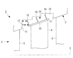
図1は、本実施形態に係る軸流タービンの構成を説明する部分断面図である。
軸流タービン1には、図1に示すように、内部に燃焼ガスなどの高温流体が流れる主流流路2が形成されるケーシング3と、回転軸(図示せず)とともに回転軸線C回りに回転可能に配置された動翼4と、ケーシング3に取り付けられた静翼5と、が設けられている。
[First Embodiment]
Hereinafter, will be explained in the axial-flow turbine according to a first embodiment of the present invention with reference to FIG. 1 to FIG.
FIG. 1 is a partial cross-sectional view illustrating a configuration of an axial turbine according to the present embodiment.
As shown in FIG. 1, the
ケーシング3は略円筒状に形成された部材であって、内部に主流流路2や、動翼4や、静翼5が配置されるものである。
ケーシング3における動翼4および静翼5が配置された領域は、図1に示すように、内周面が、上流側から下流側に向かって(図1の左側から右側に向かって)、回転軸線Cを中心とする径方向外側に向かって傾斜して形成されている。
The
As shown in FIG. 1, the inner circumferential surface of the
さらに、ケーシング3における動翼4と対向する内周面には、回転軸線Cを中心とする径方向外側に向かって凹状に形成されたキャビティ部10が設けられている。言い換えると、キャビティ部10は、ケーシング3の内周面に形成された円環状の溝部である。
キャビティ部10に隣接するケーシング3の内周面には、静翼5がキャビティ部10に沿って、略等間隔に並ぶとともに、径方向内側に向かって延びて配置されている。
Furthermore, a
On the inner peripheral surface of the
なお、ケーシング3における動翼4および静翼5が配置された領域よりも上流側(図1の左側)には、外部の空気を圧縮する圧縮機や、圧縮された空気に燃料を混合させ燃焼を行う燃焼器などが配置されていてもよく、特に限定するものではない。
In addition, on the upstream side (left side in FIG. 1) of the
キャビティ部10には、径方向外側に向かって、回転軸線Cに対して略垂直に延びる一対の側壁面11と、一対の側壁面11の間を繋ぐように形成された周壁面12と、側壁面11に設けられた仕切り板(仕切り部)13と、が設けられている。
The
周壁面12は、上流側から下流側に向かって、回転軸線Cまでの距離つまり半径が離散的に大きくなるステップ状の段が形成されている。周壁面12における段は、後述する動翼4のシールフィン16の数に対応して定められている。具体的には、周壁面12における動翼4と対向する周状の面の数が、シールフィン16の数と対応して定められている。例えば、上述の周状の面の数が、シールフィン16の数と同数になるように形成されている。
本実施形態では、周状の面の数およびシールフィン16の数がともに3つの例に適用して説明するが、この例に限定されるものではない。
The
In the present embodiment, the number of circumferential surfaces and the number of
仕切り板13は、動翼4とキャビティ部10との間の隙間を流れるバイパス流れを抑制するとともに、動翼4とキャビティ部10との間の空間における渦の発生を抑制するものである。
仕切り板13は、図1に示すように、上流側の側壁面11から動翼4に向かって、回転軸線C方向に沿って延びる略円筒状の板部材である。より具体的には、仕切り板13は、側壁面11におけるシールフィン16の根元、言い換えると、シールフィン16とシュラウド15との接合部と対向する領域の近傍から、シールフィン16に向かって延びるように設けられている。
The
As shown in FIG. 1, the
仕切り板13における側壁面11からシールフィン16への突出量は、仕切り板13の先端からシールフィン16や、シュラウド15などまでの距離が、シールフィン16の先端から側壁面11までの距離と略等しくなる程度に設定されている。さらに、仕切り板13の突出量は、仕切り板13が主流流路2内にはみ出ない程度に設定されている。
The protruding amount of the
なお、上述のキャビティ部10や仕切り板13などを有するケーシング3は、鋳物の一体形成で製造されてもよいし、仕切り板13など別個に製造し、後で溶接などの方法でケーシング3に取り付けてもよく、特に限定するものではない。
The
動翼4には、径方向外側の端部つまり翼端に配置されたシュラウド15と、シュラウド15における径方向外側の面つまり外周面に配置されたシールフィン16と、が設けられている。
シュラウド15は、動翼4の翼端に設けられた周方向に延びる部材である。なお、シュラウド15の形状としては、公知の形状を用いることができ、特に限定するものではない。
The moving
The
シールフィン16は、動翼4のシュラウド15と、キャビティ部10の周壁面12との隙間を狭めてTipクリアランスを形成することにより、Tipクリアランスを介して動翼4を迂回して下流に向かって流れるバイパス流れを抑制するものである。
シールフィン16は、シュラウド15の外周面から周壁面12に向かって延びるリング板状の部材であって、複数のシールフィン16が回転軸線C方向に沿って間隔を開けて配置されている。より詳細には、シールフィン16は、シュラウド15の外周面から径方向外側に向かって、上流側(図1の左側)に傾斜する傾斜面を有する部材である。シールフィン16の傾斜角としては、主流流路2を流れる流体流れに対して、シールフィン16の面が略直交する傾斜角を例示することができる。
The
The
なお、シールフィン16の傾斜角は、上述の傾斜角に限定されるものではなく、その他のさまざまな傾斜角であってもよく、特に限定するものではない。
The inclination angle of the
動翼4とキャビティ部10との間には、動翼4の回転を可能にするとともに、動翼4とキャビティ部10との干渉を避けるため、所定の間隔の隙間(クリアランス)が設けられている。クリアランスは、動翼4やケーシング3などの熱膨張による伸縮差を吸収するとともに、スラストによる動翼4の移動量などを吸収できる間隔に設定されている。
A gap (clearance) with a predetermined interval is provided between the
次に、上記の構成からなる軸流タービン1における流体の流れについて説明する。
軸流タービン1の主流流路2を流れる流体は、図1に示すように、静翼5および動翼4の間を流れ、動翼4を回転軸線C回りに回転駆動させながら、上流側から下流側に向かって流れる。
このとき、主流流路2を流れる流体の一部は、動翼4を迂回して、ケーシング3と動翼4との間を流れるバイパス流れとなる。
Next, the flow of fluid in the
As shown in FIG. 1, the fluid flowing through the
At this time, a part of the fluid flowing through the
バイパス流れは、キャビティ部10とシュラウド15との間の隙間のうち、上流側の隙間であるキャビティ入口部から、キャビティ部10の内部に流入する。このとき、キャビティ部10と動翼4との最小隙間は、仕切り板13とシールフィン16またはシュラウド15との間の隙間、および、仕切り板13の先端と側壁面11との間の隙間の少なくとも一方となっている。そのため、仕切り板13が設けられていない場合と比較して、キャビティ部10内における流体の流路面積が狭くなり、流体の主流流路2からキャビティ部10への流入流量は減少する。
The bypass flow flows into the
さらに、流体がキャビティ部10に流入する際、側壁面11からシールフィン16に向かって突出する仕切り板13により、渦状の流れが阻害される。
Further, when the fluid flows into the
キャビティ部10に流入した流体は、周壁面12とシールフィン16との隙間であるTipクリアランスを流れた後に、下流側の側壁面11とシュラウド15との隙間であるキャビティ出口部から主流流路2に流入する。
The fluid that has flowed into the
上記の構成によれば、主流流路2からキャビティ部10に流体が流入し、キャビティ部10とシールフィン16との間の空間で渦が発生する場合であっても、仕切り板13がキャビティ部10の側壁面11から突出しているため、流体の渦状の流れは仕切り板13により遮られる。
そのため、動翼4を迂回して流れるバイパス流れ、言い換えると、主流流路2からキャビティ部10に流入し、動翼4に設けられたシールフィン16とキャビティ部10との間のTipクリアランスを流れるバイパス流れの乱れを抑制することができ、軸流タービン1の性能低下を防止することができる。
According to the above configuration, even when the fluid flows into the
Therefore, a bypass flow that flows around the
仕切り板13を略円筒状の板部材とすることにより、仕切り板13を段差状に形成する場合と比較して、仕切り板13の重量を軽減することができる。そのため、軸流タービン1の重量の増加を防止することができる。さらに、仕切り板13を構成するのに必要な材料を削減できるため、軸流タービン1の製造コスト増加を防止することができる。
例えば、重量の増加を防止する効果は、軸流タービン1を航空分野に用いた場合に好適な効果である。一方、製造コスト増加を防止する効果は、軸流タービン1を産業分野に用いた場合に好適な効果である。
By using the
For example, the effect of preventing an increase in weight is a favorable effect when the
シールフィン16が上述のように傾斜を有するリング板状の部材であっても、シールフィン16とキャビティ部10との間隔が広い領域に向かって仕切り板13を突出させることで、動翼4を迂回するバイパス流れの流路を絞ることができるため、バイパス流れの流量を抑制することができる。
Even if the
〔第2の実施形態〕
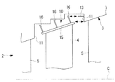
図2は、本発明の第2の実施形態に係る軸流タービンの構成を説明する部分断面図である。
なお、上述の実施形態のように、仕切り板13を上流側の側壁面11に設けてもよいし、図2に示すように、下流側の側壁面11に設けてもよいし、上流側および下流側の側壁面11の両者に仕切り板13を設けてもよく、特に限定するものではない。
[Second Embodiment]
FIG. 2 is a partial cross-sectional view illustrating the configuration of an axial turbine according to the second embodiment of the present invention .
Note that the
下流側の側壁面11に仕切り板13を設ける場合には、より具体的には、下流側の側壁面11におけるシールフィン16の先端と対向する領域に仕切り板13が設けられている。仕切り板13における側壁面11からの突出量は、仕切り板13の先端とシールフィン16との間の間隔が、シュラウド15と側壁面11との間の間隔と略等しくなるように設定されている。
When the
下流側の側壁面11に仕切り板13を設けることにより、キャビティ部10から主流流路2に流体が流出する場合であって、キャビティ部10とシールフィン16との間の空間で渦が発生する場合であっても、仕切り板13がキャビティ部10から突出しているため、流体の渦状の流れは仕切り板13により遮られる。
By providing the
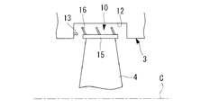
図3から図5は、図1の軸流タービンのさらに別の実施形態を説明する部分断面図である。
なお、上述の実施形態のように、ケーシング3の内周面が上流側から下流側に向かって、径方向外側に向かって傾斜して傾斜していてもよいし、図3から図5に示すように、回転軸線Cと略平行に延びる円筒面として形成されていてもよく、特に限定するものではない。
3 to 5 are partial cross-sectional views illustrating still another embodiment of the axial turbine of FIG.
In addition, like the above-mentioned embodiment, the inner peripheral surface of the
ここで、図3では、キャビティ部10の周壁面12も、回転軸線Cに沿って延びる一つの面として構成される実施形態を示している。図4では、周壁面12がステップ状の段を有する面であって、上流側(図4の左側)の周壁面12が回転軸線Cに近く、下流側(図4の右側)の周壁面12が回転軸線Cから遠い面として構成されている実施形態を示している。図5では、周壁面12がステップ状の段を有する面であって、上流側(図5の左側)の周壁面12が回転軸線Cから遠く、下流側(図5の右側)の周壁面12が回転軸線Cに近い面として構成されている実施形態を示している。
Here, FIG. 3 shows an embodiment in which the
〔第3の実施形態〕
次に、本発明の第3の実施形態について図6を参照して説明する。
本実施形態の軸流タービンの基本構成は、第1の実施形態と同様であるが、第1の実施形態とは、キャビティ部の周辺構成が異なっている。よって、本変形例においては、図6を用いてキャビティ部の周辺構成のみを説明し、その他の構成等の説明を省略する。
Third Exemplary shaped state]
Next, with the third embodiment forms state of the present invention will be described with reference to FIG.
The basic configuration of the axial turbine according to this embodiment is the same as that of the first embodiment, but the peripheral configuration of the cavity portion is different from that of the first embodiment. Therefore, in this modification, only the peripheral configuration of the cavity portion will be described with reference to FIG. 6, and description of other configurations will be omitted .
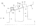
軸流タービン101のケーシング3における動翼4と対向する内周面には、図6に示すように、回転軸線Cを中心とする径方向外側に向かって凹状に形成されたキャビティ部110が設けられている。
キャビティ部110には、一対の側壁面11と、周壁面12と、側壁面11に設けられた段差状の仕切り部(段差部)113と、が設けられている。
On the inner peripheral surface of the
The
仕切り部113は、動翼4とキャビティ部110との間の隙間を流れるバイパス流れを抑制するとともに、動翼4とキャビティ部110との間の空間における渦の発生を抑制するものである。
The
仕切り部113は、図6に示すように、上流側の側壁面11から動翼4に向かって、回転軸線C方向に沿って延びる段差面を有する段差である。仕切り部113は、第1の実施形態における仕切り板13と同様に、側壁面11におけるシールフィン16の根元、言い換えると、シールフィン16とシュラウド15との接合部と対向する領域の近傍から、シールフィン16に向かって延びるように設けられている。
As shown in FIG. 6, the
仕切り部113の径方向外側の面、言い換えると、外周面は、回転軸線C方向に沿って延びる面として形成され、径方向内側の面つまり内周面は回転軸線Cに向かって上流側(図6の左側)に傾く傾斜面として形成されている。
なお、仕切り部113の形成方法としては、仕切り部113を残すように側壁面11を切削して形成する方法や、第1の実施形態の仕切り板13の径方向内側に、溶接などの方法で肉盛して仕切り部113の形状を形成する方法などを挙げることができる。
The radially outer surface of the
In addition, as a formation method of the
仕切り部113における側壁面11からシールフィン16への突出量は、仕切り部113の先端からシールフィン16や、シュラウド15などまでの距離が、シールフィン16の先端から側壁面11までの距離と略等しくなる程度に設定されている。
The protruding amount of the
上記の構成からなる軸流タービン101における流体の流れは、第1の実施形態に係る軸流タービン1における流体の流れと同様であるので、その説明を省略する。
Since the fluid flow in the
上記の構成によれば、第1の実施形態の仕切り板13と比較して、本変形例の仕切り部113はその強度を向上させることができ、軸流タービン101の強度を向上させることができる。
According to said structure, compared with the
〔第4の実施形態〕
図7は、本発明の第4の実施形態に係る軸流タービンの構成を説明する部分断面図である。
なお、上述の実施形態のように、仕切り部113を上流側の側壁面11に設けてもよいし、図7に示すように、下流側の側壁面11に設けてもよいし、上流側および下流側の側壁面11の両者に仕切り部113を設けてもよく、特に限定するものではない。
[Fourth Embodiment]
FIG. 7 is a partial cross-sectional view illustrating the configuration of an axial turbine according to the fourth embodiment of the present invention .
The
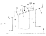
〔第5の実施形態〕
次に、本発明の第5の実施形態について図8を参照して説明する。
本実施形態の軸流タービンの基本構成は、第1の実施形態と同様であるが、第1の実施形態とは、キャビティ部の周辺構成が異なっている。よって、本実施形態においては、図8を用いてキャビティ部の周辺構成のみを説明し、その他の構成要素等の説明を省略する。
[ Fifth Embodiment]
Next, a fifth embodiment of the present invention will be described with reference to FIG.
The basic configuration of the axial turbine according to this embodiment is the same as that of the first embodiment, but the peripheral configuration of the cavity portion is different from that of the first embodiment. Therefore, in the present embodiment, only the peripheral configuration of the cavity portion will be described with reference to FIG. 8, and description of other components and the like will be omitted .
軸流タービン201のケーシング3における動翼4と対向する内周面には、図8に示すように、回転軸線Cを中心とする径方向外側に向かって凹状に形成されたキャビティ部210が設けられている。
キャビティ部210には、一対の側壁面11と、周壁面12と、側壁面11に設けられた段差状の仕切り板(仕切り部)213と、が設けられている。
On the inner peripheral surface of the
The
仕切り板213は、動翼4とキャビティ部210との間の隙間を流れるバイパス流れを抑制するとともに、動翼4とキャビティ部210との間の空間における渦の発生を抑制するものである。
The
仕切り板213は、図8に示すように、上流側の側壁面11から動翼4に向かって、径方向内側つまり回転軸線Cに向かって傾斜するリング板状の板部材である。より具体的には、仕切り板213は、シールフィン16と略平行に延びるリング板状の板部材であって、仕切り板213とシールフィン16との間隔は、上流側のシュラウド15と側壁面11との間隔と略等しくなるように設定されている。
仕切り板213はキャビティ部210内に収まるように、つまり、仕切り板213の先端言い換えると内周側の端部は、キャビティ部210内に収まるように構成されている。
As shown in FIG. 8, the
The
次に、上記の構成からなる軸流タービン201における流体の流れについて説明する。
なお、主流流路2における流体の流れについては、第1の実施形態と同様であるので、その説明を省略し、ここではバイパス流れについて説明する。
Next, the flow of fluid in the
Since the fluid flow in the
バイパス流れは、キャビティ部210とシュラウド15との間の上流側の隙間であるキャビティ入口部から、キャビティ部210の内部に流入する。このとき、キャビティ部10と動翼4との最小隙間は、仕切り板213とシールフィン16またはシュラウド15との間の隙間と同等の隙間になっている。そのため、仕切り板13が設けられていない場合と比較して、キャビティ部10内における流体の流路面積が狭くなり、流体の主流流路2からキャビティ部10への流入流量は減少する。
The bypass flow flows into the
さらに、キャビティ部210内の流路面積が狭くなっているため、流体が渦状に流れにくくなり、キャビティ部210内での渦の発生が抑制される。
Furthermore, since the flow path area in the
キャビティ部210に流入した流体は、周壁面12とシールフィン16との隙間であるTipクリアランスを流れた後に、下流側の側壁面11とシュラウド15との隙間であるキャビティ出口部から主流流路2に流入する。
The fluid that has flowed into the
上記の構成によれば、シールフィン16が上述のように傾斜を有するリング板状の部材であっても、シールフィン16とキャビティ部210との間隔が広い領域に向かって、シールフィン16と略平行に仕切り部を延ばすことで、動翼4を迂回するバイパス流れの流路を絞ることができ、バイパス流れの流量を抑制することができる。
According to the above configuration, even if the
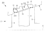
〔第6の実施形態〕
次に、本発明の第6の実施形態について図9を参照して説明する。
ここでは、上述の実施形態が、仕切り板213を上流側の側壁面11に設けているのに対し、下流側の周壁面12に仕切り板213が設けてられている。なお、上流側の側壁面11および下流側の周壁面12の両者に仕切り板213を設けてもよく、特に限定するものではない。
[Sixth Embodiment]
Next, a sixth embodiment of the present invention will be described with reference to FIG.
Here, in the above-described embodiment, the
下流側の周壁面12に仕切り板213を設ける場合には、より具体的には、下流側の周壁面12から仕切り板213が、シールフィン16と略平行に延びるように設けられている。仕切り板213とシールフィン16との間隔は、例えば、下流側のシュラウド15と側壁面11との間隔と略同等になるように設定されている。
When the
下流側の周壁面12に仕切り板213を設けることにより、キャビティ部210から主流流路2に流体が流出する場合であって、キャビティ部210とシールフィン16との間の空間で渦が発生する場合であっても、仕切り板213がキャビティ部210から突出しているため、流体の渦状の流れは仕切り板213により遮られる。
By providing the
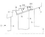
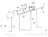
〔第7の実施形態〕
次に、本発明の第7の実施形態について図10を参照して説明する。
本実施形態の軸流タービンの基本構成は、第1の実施形態と同様であるが、第1の実施形態とは、キャビティ部の周辺構成が異なっている。よって、本変形例においては、図10を用いてキャビティ部の周辺構成のみを説明し、その他の構成等の説明を省略する。
[ Seventh Embodiment]
Next, a seventh embodiment of the present invention will be described with reference to FIG.
The basic configuration of the axial turbine according to this embodiment is the same as that of the first embodiment, but the peripheral configuration of the cavity portion is different from that of the first embodiment. Therefore, in this modification, only the peripheral configuration of the cavity portion will be described with reference to FIG.
軸流タービン301のケーシング3における動翼4と対向する内周面には、図11に示すように、回転軸線Cを中心とする径方向外側に向かって凹状に形成されたキャビティ部310が設けられている。
キャビティ部310には、一対の側壁面11と、周壁面12と、側壁面11に設けられた段差状の仕切り部(段差部)313と、が設けられている。
On the inner peripheral surface of the
The
仕切り部313は、動翼4とキャビティ部310との間の隙間を流れるバイパス流れを抑制するとともに、動翼4とキャビティ部310との間の空間における渦の発生を抑制するものである。
The
仕切り部313は、図6に示すように、上流側の側壁面11から径方向内側つまり回転軸線Cに向かって、シールフィン16と略平行に延びる段差面を有する段差である。仕切り部313は、側壁面11におけるシールフィン16と対向する領域に設けられている。
As shown in FIG. 6, the
なお、仕切り部313の形成方法としては、仕切り部313を残すように側壁面11を切削して形成する方法や、第2の実施形態の仕切り板213の径方向内側に、溶接などの方法で肉盛して仕切り部313の形状を形成する方法などを挙げることができる。
In addition, as a formation method of the
上記の構成からなる軸流タービン301における流体の流れは、第2の実施形態に係る軸流タービン201における流体の流れと同様であるので、その説明を省略する。
Since the fluid flow in the
上記の構成によれば、第2の実施形態の仕切り板213と比較して、本変形例の仕切り部313はその強度を向上させることができ、軸流タービン301の強度を向上させることができる。
According to said structure, compared with the
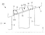
〔第8の実施形態〕
図11は、本発明の第8の実施形態に係る軸流タービンの構成を説明する部分断面図である。
なお、上述の実施形態のように、仕切り部313を上流側の側壁面11に設けてもよいし、図11に示すように、下流側の周壁面12に設けてもよいし、上流側の側壁面11および下流側の周壁面12の両者に仕切り部313を設けてもよく、特に限定するものではない。
[ Eighth Embodiment]
FIG. 11 is a partial cross-sectional view illustrating the configuration of an axial turbine according to the eighth embodiment of the present invention.
In addition, like the above-mentioned embodiment, the
1,101,201,301 軸流タービン
2 主流流路
3 ケーシング
4 動翼
10,110,210,310 キャビティ部
11 側壁面
12 周壁面
13,213 仕切り板(仕切り部)
16 シールフィン
113,313 仕切り部(段差部)
C 回転軸線
1, 101, 201, 301
16 Seal fin 113,313 Partition part (step part)
C axis of rotation
Claims (4)
前記ケーシングにおける前記動翼と対向する位置に、凹状に形成されたキャビティ部と、
前記動翼の端部から、前記キャビティ部に向かって径方向外側に延びるシールフィンと、
前記キャビティ部の壁面から、前記キャビティ部と前記シールフィンとの間隔を狭める方向に突出する、前記回転軸線を中心とする環状の仕切り部と、
が設けられ、
前記シールフィンは、径方向外側に向かって、前記回転軸線における一方の端部または他方の端部に向かって傾斜するリング板状の部材であって、
前記仕切り部は、前記キャビティ部における径方向に延びる側壁面から、前記シールフィンに向かって突出し、且つ、傾斜している該シールフィンの、先端部と、前記動翼との接合部とのうち、前記側壁面から離れている方に向かって延びていることを特徴とする軸流タービン。 A rotor blade that rotates about the axis of rotation in the mainstream flow path of the casing;
A cavity portion formed in a concave shape at a position facing the rotor blade in the casing;
A seal fin extending radially outward from the end of the rotor blade toward the cavity;
An annular partition portion centering on the rotation axis that protrudes from the wall surface of the cavity portion in a direction that narrows the gap between the cavity portion and the seal fin;
Is provided,
The seal fin is a ring plate-shaped member that is inclined toward the outer side in the radial direction toward one end or the other end of the rotation axis,
The partition portion projects from the side wall surface extending in the radial direction in the cavity portion toward the seal fin and is inclined and includes a tip portion of the seal fin and a joint portion between the moving blades The axial flow turbine extends in a direction away from the side wall surface.
前記ケーシングにおける前記動翼と対向する位置に、凹状に形成されたキャビティ部と、
前記動翼の端部から、前記キャビティ部に向かって径方向外側に延びるシールフィンと、
前記キャビティ部の壁面から、前記キャビティ部と前記シールフィンとの間隔を狭める方向に突出する、前記回転軸線を中心とする環状の仕切り部と、
が設けられ、
前記シールフィンは、径方向外側に向かって、前記回転軸線における一方の端部または他方の端部に向かって傾斜するリング板状の部材であって、
前記仕切り部は、その前記シールフィン側の面が、前記シールフィンが延びる方向に略沿って延びていることを特徴とする軸流タービン。 A rotor blade that rotates about the axis of rotation in the mainstream flow path of the casing;
A cavity portion formed in a concave shape at a position facing the rotor blade in the casing;
A seal fin extending radially outward from the end of the rotor blade toward the cavity;
An annular partition portion centering on the rotation axis that protrudes from the wall surface of the cavity portion in a direction that narrows the gap between the cavity portion and the seal fin;
Is provided,
The seal fin is a ring plate-shaped member that is inclined toward the outer side in the radial direction toward one end or the other end of the rotation axis,
The partition portion, the surface of the said sealing fins side, characterized in that extending substantially along the direction in which the sealing fins extending axial turbine.
Priority Applications (1)
| Application Number | Priority Date | Filing Date | Title |
|---|---|---|---|
| JP2011219587A JP5374563B2 (en) | 2011-10-03 | 2011-10-03 | Axial flow turbine |
Applications Claiming Priority (1)
| Application Number | Priority Date | Filing Date | Title |
|---|---|---|---|
| JP2011219587A JP5374563B2 (en) | 2011-10-03 | 2011-10-03 | Axial flow turbine |
Related Parent Applications (1)
| Application Number | Title | Priority Date | Filing Date |
|---|---|---|---|
| JP2007212866A Division JP2009047043A (en) | 2007-08-17 | 2007-08-17 | Axial flow turbine |
Publications (2)
| Publication Number | Publication Date |
|---|---|
| JP2012002234A JP2012002234A (en) | 2012-01-05 |
| JP5374563B2 true JP5374563B2 (en) | 2013-12-25 |
Family
ID=45534465
Family Applications (1)
| Application Number | Title | Priority Date | Filing Date |
|---|---|---|---|
| JP2011219587A Active JP5374563B2 (en) | 2011-10-03 | 2011-10-03 | Axial flow turbine |
Country Status (1)
| Country | Link |
|---|---|
| JP (1) | JP5374563B2 (en) |
Families Citing this family (9)
| Publication number | Priority date | Publication date | Assignee | Title |
|---|---|---|---|---|
| FR2985759B1 (en) * | 2012-01-17 | 2014-03-07 | Snecma | MOBILE AUB OF TURBOMACHINE |
| JP5985351B2 (en) * | 2012-10-25 | 2016-09-06 | 三菱日立パワーシステムズ株式会社 | Axial flow turbine |
| JP6296649B2 (en) | 2014-03-04 | 2018-03-20 | 三菱日立パワーシステムズ株式会社 | Seal structure and rotating machine |
| JP6374760B2 (en) * | 2014-10-24 | 2018-08-15 | 三菱重工業株式会社 | Axial turbine and turbocharger |
| JP2017145813A (en) | 2016-02-19 | 2017-08-24 | 三菱日立パワーシステムズ株式会社 | Rotary machine |
| CN108204251B (en) * | 2016-12-20 | 2020-05-26 | 上海汽轮机厂有限公司 | Flow guiding structure for steam seal outlet at blade top |
| FR3065483B1 (en) | 2017-04-24 | 2020-08-07 | Safran Aircraft Engines | SEALING DEVICE BETWEEN ROTOR AND TURBOMACHINE STATOR |
| JP7145774B2 (en) | 2019-01-31 | 2022-10-03 | 三菱重工業株式会社 | rotating machinery |
| JP7122274B2 (en) | 2019-02-27 | 2022-08-19 | 三菱重工業株式会社 | axial turbine |
Family Cites Families (6)
| Publication number | Priority date | Publication date | Assignee | Title |
|---|---|---|---|---|
| JPS52156203A (en) * | 1976-06-23 | 1977-12-26 | Hitachi Ltd | Sealing device for blade head |
| JPS6123804A (en) * | 1984-07-10 | 1986-02-01 | Hitachi Ltd | Turbine stage structure |
| JPS61250304A (en) * | 1985-04-26 | 1986-11-07 | Toshiba Corp | Axial flow turbine |
| EP0903468B1 (en) * | 1997-09-19 | 2003-08-20 | ALSTOM (Switzerland) Ltd | Gap sealing device |
| JP2003106107A (en) * | 2001-09-27 | 2003-04-09 | Mitsubishi Heavy Ind Ltd | Turbine |
| JP2006104952A (en) * | 2004-09-30 | 2006-04-20 | Toshiba Corp | Swirling flow preventive device of fluid machine |
-
2011
- 2011-10-03 JP JP2011219587A patent/JP5374563B2/en active Active
Also Published As
| Publication number | Publication date |
|---|---|
| JP2012002234A (en) | 2012-01-05 |
Similar Documents
| Publication | Publication Date | Title |
|---|---|---|
| JP5374563B2 (en) | Axial flow turbine | |
| JP2009047043A (en) | Axial flow turbine | |
| EP3078888B1 (en) | Seal structure and rotary machine | |
| US9181816B2 (en) | Seal assembly including grooves in an aft facing side of a platform in a gas turbine engine | |
| US9039357B2 (en) | Seal assembly including grooves in a radially outwardly facing side of a platform in a gas turbine engine | |
| JP6109961B2 (en) | Seal assembly including a groove in an inner shroud of a gas turbine engine | |
| US20110070074A1 (en) | Gas turbine with a shroud and labyrinth-type sealing arrangement | |
| US20100196139A1 (en) | Leakage flow minimization system for a turbine engine | |
| JP2012087928A (en) | Turbomachine seal assembly | |
| JP2017141821A (en) | Centrifugal compressor assembly for use in turbine engine and method of assembly thereof | |
| JP2002371802A (en) | Shroud integrated type moving blade in gas turbine and split ring | |
| JP2011137458A (en) | System and apparatus relating to compressor operation in turbo engine | |
| KR101833660B1 (en) | Vane array and gas turbine | |
| JP6096639B2 (en) | Rotating machine | |
| JP2015129512A (en) | Steam turbine and methods of assembling the same | |
| US11268402B2 (en) | Blade outer air seal cooling fin | |
| US20160123169A1 (en) | Methods and system for fluidic sealing in gas turbine engines | |
| JP5852191B2 (en) | End wall member and gas turbine | |
| JP5404187B2 (en) | End wall member and gas turbine | |
| US10815793B2 (en) | Trip strips for augmented boundary layer mixing | |
| US9644483B2 (en) | Turbomachine bucket having flow interrupter and related turbomachine | |
| JP2019015273A (en) | Turbo machine | |
| JP5591986B2 (en) | End wall member and gas turbine | |
| JP5852190B2 (en) | End wall member and gas turbine | |
| WO2016151895A1 (en) | Exhaust turbine device and supercharger |
Legal Events
| Date | Code | Title | Description |
|---|---|---|---|
| A621 | Written request for application examination |
Free format text: JAPANESE INTERMEDIATE CODE: A621 Effective date: 20111003 |
|
| A977 | Report on retrieval |
Free format text: JAPANESE INTERMEDIATE CODE: A971007 Effective date: 20120821 |
|
| A131 | Notification of reasons for refusal |
Free format text: JAPANESE INTERMEDIATE CODE: A131 Effective date: 20120925 |
|
| A521 | Written amendment |
Free format text: JAPANESE INTERMEDIATE CODE: A523 Effective date: 20121126 |
|
| A131 | Notification of reasons for refusal |
Free format text: JAPANESE INTERMEDIATE CODE: A131 Effective date: 20130514 |
|
| A521 | Written amendment |
Free format text: JAPANESE INTERMEDIATE CODE: A523 Effective date: 20130716 |
|
| TRDD | Decision of grant or rejection written | ||
| A01 | Written decision to grant a patent or to grant a registration (utility model) |
Free format text: JAPANESE INTERMEDIATE CODE: A01 Effective date: 20130827 |
|
| A61 | First payment of annual fees (during grant procedure) |
Free format text: JAPANESE INTERMEDIATE CODE: A61 Effective date: 20130920 |
|
| R151 | Written notification of patent or utility model registration |
Ref document number: 5374563 Country of ref document: JP Free format text: JAPANESE INTERMEDIATE CODE: R151 |
|
| S111 | Request for change of ownership or part of ownership |
Free format text: JAPANESE INTERMEDIATE CODE: R313111 |
|
| R350 | Written notification of registration of transfer |
Free format text: JAPANESE INTERMEDIATE CODE: R350 |
|
| R250 | Receipt of annual fees |
Free format text: JAPANESE INTERMEDIATE CODE: R250 |