JP5374220B2 - Motion vector detection device, control method therefor, and imaging device - Google Patents
Motion vector detection device, control method therefor, and imaging device Download PDFInfo
- Publication number
- JP5374220B2 JP5374220B2 JP2009105608A JP2009105608A JP5374220B2 JP 5374220 B2 JP5374220 B2 JP 5374220B2 JP 2009105608 A JP2009105608 A JP 2009105608A JP 2009105608 A JP2009105608 A JP 2009105608A JP 5374220 B2 JP5374220 B2 JP 5374220B2
- Authority
- JP
- Japan
- Prior art keywords
- motion vector
- group
- representative
- determined
- entire image
- Prior art date
- Legal status (The legal status is an assumption and is not a legal conclusion. Google has not performed a legal analysis and makes no representation as to the accuracy of the status listed.)
- Expired - Fee Related
Links
Images


Classifications
-
- G—PHYSICS
- G06—COMPUTING; CALCULATING OR COUNTING
- G06V—IMAGE OR VIDEO RECOGNITION OR UNDERSTANDING
- G06V40/00—Recognition of biometric, human-related or animal-related patterns in image or video data
- G06V40/10—Human or animal bodies, e.g. vehicle occupants or pedestrians; Body parts, e.g. hands
- G06V40/16—Human faces, e.g. facial parts, sketches or expressions
- G06V40/161—Detection; Localisation; Normalisation
- G06V40/167—Detection; Localisation; Normalisation using comparisons between temporally consecutive images
-
- G—PHYSICS
- G06—COMPUTING; CALCULATING OR COUNTING
- G06T—IMAGE DATA PROCESSING OR GENERATION, IN GENERAL
- G06T7/00—Image analysis
- G06T7/20—Analysis of motion
- G06T7/215—Motion-based segmentation
-
- G—PHYSICS
- G06—COMPUTING; CALCULATING OR COUNTING
- G06T—IMAGE DATA PROCESSING OR GENERATION, IN GENERAL
- G06T2207/00—Indexing scheme for image analysis or image enhancement
- G06T2207/10—Image acquisition modality
- G06T2207/10016—Video; Image sequence
-
- G—PHYSICS
- G06—COMPUTING; CALCULATING OR COUNTING
- G06T—IMAGE DATA PROCESSING OR GENERATION, IN GENERAL
- G06T2207/00—Indexing scheme for image analysis or image enhancement
- G06T2207/20—Special algorithmic details
- G06T2207/20021—Dividing image into blocks, subimages or windows
Abstract
Description
本発明は、動きベクトル検出装置およびその制御方法、ならびに撮像装置関し、特には、撮影された動画像のブレを補正するために用いる動きベクトルを検出する動きベクトル検出装置およびその制御方法、ならびに撮像装置に関する。 The present invention relates to a motion vector detection device, a control method thereof, and an imaging device, and in particular, a motion vector detection device that detects a motion vector used to correct blurring of a captured moving image, a control method thereof, and imaging. Relates to the device.
ビデオカメラといった、動画像を撮影する撮像装置においては、特にレンズを望遠側にズームしたときに、撮影された画像が手ぶれによりぶれることが問題となる。このような手ぶれによる画像のぶれを防止するために、従来より、撮影した画像信号から画像の動きベクトルを検出し、この動きベクトルに基づいて画像のぶれを補正する技術が提案されている。 An imaging device such as a video camera that captures a moving image has a problem that the captured image is blurred due to camera shake, particularly when the lens is zoomed to the telephoto side. In order to prevent image blur due to such camera shake, there has conventionally been proposed a technique for detecting a motion vector of an image from a captured image signal and correcting the blur of the image based on the motion vector.
画像の動きベクトルを検出する方法としては、従来より、相関演算に基づく相関法やブロックマッチング法などが知られている。ブロックマッチング法では、画像を所定サイズのブロック(例えば8画素×8画素)に分割する。そして、このブロック単位で前のフィールド(またはフレーム)の一定範囲の画素との差分を計算し、この差分の絶対値の和が最小となる前のフィールド(またはフレーム)のブロックを探索する。そして、現在のフィールド(またはフレーム)と、前のフィールド(またはフレーム)との相対的なずれが、探索されたブロックの動きベクトルを示している。 Conventionally known methods for detecting a motion vector of an image include a correlation method based on a correlation calculation, a block matching method, and the like. In the block matching method, an image is divided into blocks of a predetermined size (for example, 8 pixels × 8 pixels). Then, the difference between the previous field (or frame) and a certain range of pixels is calculated in units of blocks, and the previous field (or frame) block in which the sum of the absolute values of the differences is minimized is searched. The relative deviation between the current field (or frame) and the previous field (or frame) indicates the motion vector of the searched block.
また、マッチング演算については、尾上守夫らにより、「情報処理Vol.17,No.7,p.634 〜640 July 1976」で詳しく論じられている。 The matching operation is discussed in detail in “Information Processing Vol. 17, No. 7, p. 634 to 640 July 1976” by Morio Onoe.
次に、ブロックマッチング法を用いた従来の動きベクトル検出法の一例を、図面を用いて説明する。図22は、従来の動きベクトル検出方法によりぶれを防止するための一例の構成を示す。動きベクトルの検出対象となる画像信号(フィールド画像信号とする)が画像メモリ101に供給され一時的に記憶されると共に、空間周波数成分を抽出するフィルタ102に供給される。フィルタ102は、画像信号から動きベクトル検出に有用な空間周波数成分を抽出する。すなわち、フィルタ102は、画像信号の空間周波数成分のうち低周波成分と高周波成分とを除去する。
Next, an example of a conventional motion vector detection method using the block matching method will be described with reference to the drawings. FIG. 22 shows an example of a configuration for preventing blurring by a conventional motion vector detection method. An image signal (referred to as a field image signal) that is a motion vector detection target is supplied to the
フィルタ102を通過した画像信号は、2値化回路103に加えられる。2値化回路103は、画像信号を、ゼロレベルを基準として2値化する。具体的には、出力信号の符号ビットを出力する。2値化された画像信号は、相関演算回路104およびメモリ105に供給される。メモリ105は、画像信号を1フィールド期間だけ遅延させるためのものである。メモリ105から読み出された1フィールド前の画像信号は、相関演算回路104に供給される。
The image signal that has passed through the
相関演算回路104は、ブロックマッチング法に従い、画像信号による画像領域を所定サイズのブロックに分割し、現フィールドと前フィールドとの相関演算をブロック毎に行う。相関演算により算出されたブロック毎の相関値は、動きベクトル検出回路106に供給される。動きベクトル検出回路106は、供給された相関値から、ブロック毎の動きベクトルを検出する。具体的には、相関値が最小となる前フィールドのブロックを探索し、その相対的なずれを動きベクトルとしている。
このブロック毎の動きベクトルは、動きベクトル決定回路107に供給される。動きベクトル決定回路107は、ブロック毎の動きベクトルから、フィールド画像全体の動きベクトルを決定する。具体的には、ブロック毎の動きベクトルの中央値または平均値を、フィールド画像全体の動きベクトルとしている。
The motion vector for each block is supplied to the motion
動きベクトル決定回路107は、決定した全体の動きベクトルをメモリ読み出し制御回路108に供給する。メモリ読み出し制御回路108は、画像メモリ101に記憶されたフィールド画像信号を読み出して出力する。このとき、メモリ読み出し制御回路108は、動きベクトル決定回路107で決定された全体の動きベクトルに応じて、画像の動きが相殺されるように画像メモリ101の読み出し位置を制御する。これにより、ぶれが補正された画像信号が画像メモリ101から出力される。
The motion
ところで、上述の従来の方法では、画像中に移動被写体がある場合、例えばブロック毎に検出された動きベクトルの平均値を全体の動きベクトルにすると、画像中の移動被写体の動きが全体の動きベクトルに混入してしまうことになる。その結果、メモリ読み出し制御回路108の制御により、移動被写体が画面内の元の位置に止まるように画像メモリ101の読み出し位置が変化する。それにより、本来動きが無いはずである画面内の領域の位置が変化するため、画面内の画像が移動物に引っ張られたような動きをしてしまう。
By the way, in the above-described conventional method, when there is a moving subject in the image, for example, if the average value of the motion vectors detected for each block is set as the entire motion vector, the movement of the moving subject in the image becomes the entire motion vector. Will be mixed in. As a result, the reading position of the
この問題を解決するために、特許文献1には、各ブロック領域に対して、重み付けの係数を設定し、各重み係数と各ブロック領域のベクトル検出値から、画面全体の動きベクトルを算出するようにした技術が開示されている。特許文献1では、画面の中央は人などの移動する被写体が存在する可能性が高いため重み付けの係数を小さくし、画面の周辺部は重み付けの係数を大きくすることにより、移動する被写体に画面内の画像が引っ張られるような動きを回避している。
In order to solve this problem,
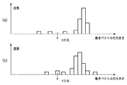
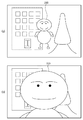
上述した特許文献1の方法では、例えば図23(a)のように、主たる被写体200(人物)の画面に占める割合が比較的小さければ、画面周辺部の背景領域の重み付け係数を大きくすることで、背景領域のぶれに近似した動きベクトルを算出できる。しかし、図23(b)に示すように、被写体200の画面に占める割合が比較的大きければ、画面周辺部の領域では被写体200と背景とが両方存在することになり、動きベクトル検出値の誤差が大きくなるという問題点があった。
In the method of
したがって、本発明の目的は、撮像画像のぶれを補正するために用いる動きベクトルを、画面内の主たる被写体の状態に関わらず高精度に求めることができる動きベクトル検出装置およびその制御方法、ならびに撮像装置を提供することにある。 Therefore, an object of the present invention is to provide a motion vector detection apparatus and its control method capable of obtaining a motion vector used for correcting blurring of a captured image with high accuracy regardless of the state of the main subject in the screen, and imaging. To provide an apparatus.
本発明は、上述した課題を解決するために、連続して撮像される画像のぶれを補正するために用いる、画像全体の動きベクトルを検出する動きベクトル検出装置であって、画像を所定サイズに分割したブロック毎に動きベクトルを検出する動きベクトル検出手段と、動きベクトル検出手段で検出された動きベクトルに基づき、ブロックのそれぞれをグループに分類する分類手段と、分類手段で分類されたグループに属するブロックの動きベクトルを代表する代表動きベクトルを算出する代表動きベクトル算出手段と、分類手段で分類されたグループが、第1のグループと、第1のグループに対して画像上で相対的に移動している第2のグループのいずれであるかを判定する第1の判定手段と、第1の判定手段により第2のグループと判定されたグループに含まれるブロックの数が閾値を超えていれば、画像全体の動きベクトルとして第2のグループに対応する代表動きベクトルを選択し、第2のグループに含まれるブロックの数が閾値を超えていなければ、画像全体の動きベクトルとして第1のグループに対応する代表動きベクトルを選択する選択手段とを有することを特徴とする動きベクトル検出装置である。 In order to solve the above-described problems, the present invention is a motion vector detection apparatus for detecting a motion vector of an entire image, which is used for correcting blurring of images that are continuously captured, and which reduces the image to a predetermined size. A motion vector detection means for detecting a motion vector for each divided block, a classification means for classifying each block into groups based on the motion vector detected by the motion vector detection means, and a group classified by the classification means The representative motion vector calculation means for calculating the representative motion vector representing the block motion vector, and the group classified by the classification means move relative to the first group and the first group on the image. A first determination unit that determines which one of the second groups is determined, and the second group is determined by the first determination unit If the number of blocks included in the group exceeds the threshold, a representative motion vector corresponding to the second group is selected as the motion vector of the entire image, and the number of blocks included in the second group exceeds the threshold. Otherwise, the motion vector detection apparatus includes selection means for selecting a representative motion vector corresponding to the first group as the motion vector of the entire image.
本発明は、撮像画像のぶれを補正するために用いる動きベクトルを、画面内の主たる被写体の状態に関わらず高精度に求めることができる。 According to the present invention, a motion vector used for correcting shake of a captured image can be obtained with high accuracy regardless of the state of the main subject in the screen.
<第1の実施形態>
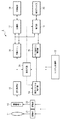
以下、本発明の第1の実施形態を、図面を参照しながら説明する。図1は、本発明に適用可能な撮像装置1の一例の構成を示す。撮像装置1は、例えば、連続して撮像される撮像画像の一例としての動画像の撮影を行うデジタルビデオカメラである。
<First Embodiment>
DESCRIPTION OF EXEMPLARY EMBODIMENTS Hereinafter, a first embodiment of the invention will be described with reference to the drawings. FIG. 1 shows an exemplary configuration of an
図1において、撮像光学系11は、レンズおよび絞りなどを含む。撮像手段としての固体撮像素子12は、CCDやCMOSセンサなどであって、撮像光学系11を介して入射された光を撮像信号に変換して出力する。駆動部21は、撮像光学系11が含むズームレンズ、フォーカスレンズおよび絞りなど(図示しない)をシステム制御部22の制御に従い駆動する。駆動部23は、システム制御部22の制御に従い固体撮像素子12を駆動する。信号処理部13は、固体撮像素子12から出力されたアナログ画像信号に対して、ノイズ除去、ゲイン制御、A/D変換、ガンマ補正およびホワイトバランス補正など必要な信号処理を行い、画像データとして出力する。
In FIG. 1, the imaging
動きベクトル検出部14は、信号処理部13で信号処理された画像データから、動きベクトルを検出する。顔検出部24は、信号処理部13から出力された画像データから顔を検出する。画像メモリ16は、信号処理部13から出力された画像データを記憶する。ぶれ補正手段としてのメモリ読み出し制御部15は、動きベクトル検出部14により検出された動きベクトルに基づき画像メモリ16からの画像データの読み出しを制御する。これにより、後述する記録媒体18に記録される画像データや、表示デバイス20に表示される画像データの範囲が決められる。
The motion
記録手段としての記録部17は、画像メモリ16から読み出された画像データを記録媒体18に記録する。このとき、記録部17は、画像データに対して所定の方式により圧縮符号化を施し、圧縮符号化された圧縮画像データを記録媒体18に記録する。記録媒体18としては、不揮発性の半導体メモリやハードディスク、光ディスクなどを適用することができる。表示部19は、画像メモリ16から読み出された画像データを表示デバイス20の表示解像度に合わせて解像度変換し、表示デバイス20に表示させる。
The
システム制御部22は、例えばCPU、ROMおよびRAMを有し、ROMに予め記憶されたプログラムに従い、RAMをワークメモリとして用いて、この撮像装置1の各部を制御する。
The
次に、上述のような構成の撮像装置1における一例の撮影動作について説明する。駆動部21は、システム制御部22からの制御信号に基づいて、撮像光学系11内のズームレンズ、フォーカスレンズ、絞りを駆動して、被写体像を撮像素子12上に結像させる。撮像素子12は、システム制御部22により制御される駆動部21が発生する駆動パルスにより駆動され、被写体像を光電変換して電気信号に変換し、アナログ画像信号を出力する。
Next, an example of an imaging operation in the
撮像素子12から出力されたアナログ画像信号は、信号処理部13に供給され、信号処理部13が有するA/D変換器でデジタル画像信号に変換される。信号処理部13は、システム制御部22の制御に従い、デジタル画像信号に対して、色変換処理、ホワイトバランス補正処理、ガンマ補正処理などの画像処理を行う。画像メモリ16は、信号処理部13で信号処理中のデジタル画像信号を一時的に記憶したり、信号処理されたデジタル画像信号である画像データを記憶するために用いられる。
The analog image signal output from the
動きベクトル検出部14は、本発明に係る動きベクトル検出装置としての処理を行う部分で、信号処理部13で信号処理された画像データから動きベクトルを検出し、動きベクトル情報として出力する。動きベクトル検出部14における動きベクトル検出処理の詳細については、後述する。メモリ読み出し制御部15は、動きベクトル検出部14により検出された動きベクトル情報に基づいて画像メモリ16からの画像データの読み出しを制御し、画像ぶれが補正されるように、記録または表示する画像データの範囲を決定する。
The motion
顔検出手段としての顔検出部24は、信号処理部13で信号処理された画像データから顔を検出し、画像データ上での顔の位置を算出する。算出された画像データ上の顔の位置は、画像データと共に、顔検出枠として表示部19により表示デバイス20に表示させることができる。
The
なお、顔検出部24での顔検出には、公知の顔検出技術を利用できる。公知の顔検出技術としては、ニューラルネットワークなどを利用した学習に基づく手法、テンプレートマッチングを用いて目、鼻、口等の形状に特徴のある部位を画像から探し出し、類似度が高ければ顔とみなす手法などがある。また、他にも、肌の色や目の形といった画像特徴量を検出し、統計的解析を用いた手法等、多数提案されている。一般的にはこれらの手法を複数組み合わせ、顔検出の精度を向上させている。具体的な例としては特開2002−251380号公報に記載のウェーブレット変換と画像特徴量を利用して顔検出する方法などが挙げられる。
A known face detection technique can be used for the face detection by the
信号処理部13で信号処理され画像メモリ16に記憶されている画像データは、記録部17において、記録媒体18への記録に適したデータに変換されて記録媒体18に記録される。例えば、記録部17は、供給された画像データを、例えば階層構造を持つファイルシステムによるファイルに格納して、記録媒体18に記録する。
The image data signal-processed by the
また、画像メモリ16から読み出された画像データは、表示部19において表示デバイス20の表示解像度に合わせて解像度変換される。表示部19は、さらに、解像度変換された画像データを、表示デバイス20に適した信号、例えばNTSC方式のアナログ画像信号に変換して表示デバイス20に供給する。
Further, the image data read from the
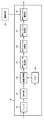
図2は、上述した、本発明に係る動きベクトル検出部14の一例の構成を示す。信号処理回路から出力された例えばフィールド画像による画像データは、画像メモリ16に記憶されると共に、フィルタ33に供給される。フィルタ33は、画像データから、空間周波数の低周波成分と高周波成分とを除去し、動きベクトル検出に有用な空間周波数成分を抽出する。フィルタ33から出力された画像データは、2値化部34で例えばゼロレベルを基準として2値化され、相関演算部35に供給されると共に、メモリ36に記憶される。メモリ36は、画像データを1フィールド分遅延させるためのものである。
FIG. 2 shows the configuration of an example of the motion
相関演算部35は、ブロックマッチング法に従い、画像データによる画像領域を、例えば8画素×8画素といった所定サイズのブロックに分割し、現フィールドと前フィールドとの相関演算をブロック毎に行う。相関演算により算出された相関値は、動きベクトル検出部37に供給される。動きベクトル検出手段としての動きベクトル検出部37は、供給された相関値からブロック毎の動きベクトルを検出する。具体的には、相関値が最小となる前フィールドのブロックを探索し、その相対的なずれを動きベクトルとしている。
The
動きベクトル検出部37で検出されたブロック毎の動きベクトルは、分類手段としての動きベクトル分類部30に供給される。動きベクトル分類部30は、供給されたブロックを、X方向(画面の水平方向)およびY方向(画面の垂直方向)それぞれの動きベクトル値に基づきグループに分類する。動きベクトル分類部30で分類されたブロックの動きベクトル値は、動きベクトル演算部31に供給される。
The motion vector for each block detected by the motion
代表動きベクトル算出手段としての動きベクトル演算部31は、動きベクトル分類部30で分類されたグループ毎に、グループとしての代表動きベクトルを求める。代表動きベクトルは、例えば動きベクトル値の出現頻度のヒストグラムを取ったときの、グループ内で最大度数を持つ階級の階級値を用いることができる。これに限らず、グループに属する全てのベクトル検出領域で検出された動きベクトル値の平均値を、グループとしての代表動きベクトルとして用いることもできる。
The motion
動きベクトル演算部31で求められたグループ毎の代表動きベクトルは、第1の判定手段、第2の判定手段および選択手段としての動きベクトル制御部32に供給される。動きベクトル制御部32には、さらに、顔検出部24から顔検出情報が供給される。動きベクトル制御部32は、これらグループ毎の代表動きベクトルと、顔検出情報とを用いて、画面全体すなわち1フィールドの画像全体での動きベクトル(全体動きベクトルと呼ぶ)を算出する。
The representative motion vector for each group obtained by the motion
動きベクトル制御部32で算出された全体動きベクトルは、メモリ読み出し制御部15に供給される。メモリ読み出し制御部15により、この全体動きベクトルに基づき画像メモリ16に記憶される画像データの読み出しを制御することで、手ぶれ補正を行うことができる。
The entire motion vector calculated by the motion
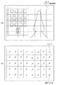
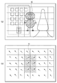
次に、上述した動きベクトル分類部30における処理について、より詳細に説明する。先ず、相関演算部35および動きベクトル検出部37において、図3(a)に例示されるように、撮影され入力された画像データによる画面を、所定サイズのブロックに分割する。そして、図3(b)に例示されるように、ブロック毎に動きベクトルを検出する。以下、この動きベクトルを検出するためのブロックを、ベクトル検出領域と呼ぶ。
Next, the process in the motion
動きベクトル分類部30は、このベクトル検出領域毎の動きベクトルから、動きベクトルの大きさに関する度数分布を、画面の水平および垂直方向にそれぞれについて求める。図4は、こうして求めた度数分布の例を示すヒストグラムである。図4(a)が画面の水平方向(X方向)について求めた度数分布をプロットしたヒストグラムの例、図4(b)が画面の垂直方向(Y方向)について求めた度数分布をプロットしたヒストグラムの例である。
The motion
より具体的には、動きベクトル分類部30は、動きベクトルの大きさについて、所定の範囲毎に区切って階級を設定する。そして、動きベクトル検出部37で検出された動きベクトルの大きさに基づき、ベクトル検出領域が何れの階級に属するかを判定し、判定結果に応じてベクトル検出領域を階級に分類し、当該階級に対して度数を加算する。この処理を、画面内の全てのベクトル検出領域について、画面の水平および垂直方向に対してそれぞれ行う。
More specifically, the motion
図3(b)の例によれば、画面が40個のベクトル検出領域に分割されているので、画面内の動きベクトルとして、合計で40個の動きベクトルが検出される。すなわち、画面内の度数の合計は、40である。この40の度数を、動きベクトルの大きさに基づき階級に振り分けて階級毎に加算することで、各階級におけるベクトル検出領域の度数(頻度)を得ることができる。なお、それぞれ範囲を持つ階級の階級値としては、その階級の上限値と下限値の中間値を用いればよい。 According to the example of FIG. 3B, since the screen is divided into 40 vector detection areas, a total of 40 motion vectors are detected as motion vectors in the screen. That is, the total number of frequencies in the screen is 40. By dividing the 40 frequencies into classes based on the magnitude of the motion vector and adding each class, the frequency (frequency) of the vector detection area in each class can be obtained. As the class value of each class having a range, an intermediate value between the upper limit value and the lower limit value of the class may be used.
動きベクトル分類部30は、動きベクトルの度数分布に基づき、各ベクトル検出領域をさらにグループに分類する。この度数分布に基づくベクトル検出領域のグループ分類について、図5および図6を用いて説明する。図5(a)に示すように、画面内に存在する主たる被写体42(斜線を付して示す)がフィールド間で移動した場合について考える。この場合、図5(b)に例示されるように、主たる被写体42が含まれるベクトル検出領域による領域43内の動きベクトルは、領域43以外のベクトル検出領域の動きベクトルとは異なったものとなる。例えば、この図5の例では、領域43が画面の右上方向に移動し、領域43以外の部分が画面の左上方向に移動している。なお、以下では、主たる被写体が含まれるベクトル検出領域による領域を、主被写体領域と呼ぶ。
The motion
このとき、例えば画面水平方向における動きベクトルの大きさに基づく度数分布は、図6にヒストグラムで例示されるように、2つのピークが存在する形となる。このとき、1つのピークを構成する度数が属する階級に基づき、グループを形成する。図6の例では、領域43以外の部分による、画面の左上方向に移動する動きベクトルの度数のピークに基づくグループ#1と、領域43による、画面の右上方向に移動する動きベクトルの度数のピークに基づくグループ#2とが形成される。
At this time, for example, the frequency distribution based on the magnitude of the motion vector in the horizontal direction of the screen has a form in which there are two peaks as exemplified by the histogram in FIG. At this time, a group is formed based on the class to which the frequencies constituting one peak belong. In the example of FIG. 6, by a portion other than the
図5(a)および図5(b)と、図6とを対比させることで、グループ#2が被写体42が含まれる領域43の動きベクトルに基づくグループで、グループ#1が領域43以外(背景領域)の動きベクトルに基づくグループであることが理解できる。しかしながら、データ上では、分離され得る2つのグループが検出できたに過ぎない。すなわち、データ上では、グループ#1および#2の何れが手ぶれのみの動きベクトルに基づくグループであり、何れが手ぶれに被写体の動きベクトルが重畳された動きベクトルに基づくグループであるかは分からない。動きベクトルに基づくグループが手ぶれのみの動きベクトルを表すグループか、手ぶれに被写体の動きが重畳された動きベクトルに基づくグループかを判断する方法については、後述する。
By comparing FIG. 5 (a) and FIG. 5 (b) with FIG. 6, group # 2 is a group based on the motion vector of
検出された動きベクトルに基づきベクトル検出領域をグループに分類する方法について、より具体的に説明する。動きベクトル分類部30は、図6のようにして得られた動きベクトルの度数分布に対し、階級403および405のような極値(ピーク)を探索する。ここで、動きベクトル分類部30は、予め決められた閾値pより大きい度数をグループ分類に際して有効な度数とし、この閾値pより大きく、且つ、両隣の所定範囲の階級の度数よりも大きい度数を、極値として検出するものとする。
A method for classifying the vector detection areas into groups based on the detected motion vectors will be described more specifically. The motion
さらに、動きベクトル分類部30は、極値が複数見つかった場合、互いに隣り合う極値について、極値に対応する階級間の距離Dを求める。そして、この距離Dが予め決めれらた閾値cを超えるものであるか否かを判定する。ここで、距離cは、動きベクトル検出部37による動きベクトル検出誤差よりも大きな値に設定される。
Further, when a plurality of extreme values are found, the motion
若し、求められた距離Dが予め決められた閾値cを超えていれば、それぞれの極値を構成する度数が属する階級が互いに別グループを形成すると判定する。一方、求められた距離Dが予め決められた閾値cを超えていないとされれば、それぞれの極値を構成する度数が属する階級は、同一のグループを形成すると判定する。 If the obtained distance D exceeds a predetermined threshold c, it is determined that the classes to which the frequencies constituting the respective extreme values belong to another group. On the other hand, if the determined distance D does not exceed the predetermined threshold c, it is determined that the classes to which the frequencies constituting the respective extreme values belong form the same group.
図6の例では、度数が閾値pより大きな、グループ分類に際して有効な度数を有する階級を、階級401〜405として検出する。そして、両隣の階級より大きな度数を持つ階級403および405を、極値として検出する。さらに、極値として検出された階級403および405の間の距離は、距離Dであって、閾値cより大きいので、階級403および405は、それぞれ別のグループに分類されると判定できる。
In the example of FIG. 6, classes having frequencies greater than the threshold value p and having frequencies effective for group classification are detected as
さらに、極値である階級403に隣接する階級402は、度数が閾値pを超えるため有効であり、且つ、階級403との距離が閾値cを超えないので、階級403と同一のグループ#1に分類される。これは、階級403に隣接する階級401についても、同様である。また、極値を取る階級405に隣接する階級404は、度数が閾値pを超えるため有効であり、且つ、階級405との距離が閾値cを超えないので、階級405と同一のグループ#2に分類される。
Furthermore, the
このようにして、動きベクトル分類部30では、各ベクトル検出領域が、各ベクトル検出領域毎に検出された動きベクトルに基づき1つ以上のグループに分類される。動きベクトル分類部30で得られた各グループの情報は、例えば動きベクトル検出部14が有する図示されないメモリなどに保持される。グループの情報は、例えばグループを識別する識別情報、グループに含まれるベクトル検出領域を示す情報(座標情報など)、当該ベクトル検出領域の動きベクトルを示す情報などからなる。
In this manner, the motion
次に、上述した動きベクトル演算部31における処理について説明する。動きベクトル演算部31では、動きベクトル分類部30にて定められたグループ毎に、グループとしての代表動きベクトルを求める。代表動きベクトルは、各グループの中で最も大きな度数を持つ階級の階級値とする。また、グループに属する全てのベクトル検出領域で検出された動きベクトルの値の平均値を、グループとしての代表動きベクトルとしても良い。
Next, the process in the motion
<第1の実施形態による全体動きベクトル算出処理>
次に、動きベクトル制御部32における処理について、より詳細に説明する。上述したように、動きベクトル制御部32では、画面全体すなわち1フィールドの画像全体の動きベクトル(全体動きベクトル)を算出する。動きベクトル制御部32は、動きベクトル分類部30でのグループ分類の結果と、動きベクトル演算部31で算出された各グループの代表ベクトル値と、顔検出部24で検出された顔検出情報などを用いて、全体動きベクトルを算出する。
<Overall Motion Vector Calculation Processing According to First Embodiment>
Next, the processing in the motion
図7は、本発明の第1の実施形態による全体動きベクトルの算出処理を示す一例のフローチャートである。図7のフローチャートにおける各処理は、システム制御部22の制御に従い動きベクトル制御部32により実行される。
FIG. 7 is a flowchart of an example showing the entire motion vector calculation process according to the first embodiment of the present invention. Each process in the flowchart of FIG. 7 is executed by the motion
先ず、ステップS10で、動きベクトル制御部32は、動きベクトル分類部30が現在の画像データ、すなわち、現フィールドの画像データにおいて複数個のグループを検出したか否かを判定する。若し、検出されたグループが1つであると判定された場合は、処理はステップS11に移行され、検出されたグループの代表動きベクトルを全体動きベクトルとして採用する。そして、次のフィールド画像に対する処理が開始される(図示しない)。
First, in step S10, the motion
一方、ステップS10で、動きベクトル分類部30にて検出されたグループが複数個存在すると判定された場合は、処理はステップS12に移行される。ステップS12で、動きベクトル制御部32は、動きベクトル分類部30で検出された各グループが背景領域のベクトル検出領域によるものか、主被写体領域のベクトル検出領域によるものかの判定を行う。
On the other hand, if it is determined in step S10 that there are a plurality of groups detected by the motion
<判定処理の第1の方法>
ステップS12での判定処理の第1の方法について、詳細に説明する。ここで、現フィールド画像が上述した図5(a)に例示するものであって、図5(b)のように各ベクトル検出領域における動きベクトルが検出され、図6に示されるように、各ベクトル検出領域がグループ#1および#2に分類されたものとする。ステップS12において、動きベクトル制御部32は、図8(a)に例示されるように、各ベクトル検出領域の画面内における座標を定義する。
<First method of determination processing>
The first method of the determination process in step S12 will be described in detail. Here, the current field image is exemplified in FIG. 5A described above, and the motion vector in each vector detection area is detected as shown in FIG. 5B, and as shown in FIG. It is assumed that the vector detection area is classified into
次に、動きベクトル制御部32は、各グループ#1および#2のそれぞれについて、属するベクトル検出領域の重心座標(GX,GY)と、各ベクトル検出領域の座標の重心座標に対するばらつきを示すばらつき値Zとを求める。X方向(画面水平方向)のグループの重心座標GXは、グループに属する各ベクトル検出領域のX方向の座標Xの平均値とする。Y方向(画面垂直方向)のグループの重心座標GYについても、同様とする。
Next, for each of the
一例として、上述の図6におけるグループ#2に属するベクトル検出領域は、図8(b)に斜線で示す領域50に含まれる6個のベクトル検出領域となる。すなわち、領域50に含まれるブロック数は6個である。各ベクトル検出領域の座標を、下記に示す。
領域#1:(X3,Y1)
領域#2:(X3,Y2)
領域#3:(X3,Y3)
領域#4:(X4,Y1)
領域#5:(X4,Y2)
領域#6:(X4,Y3)
As an example, the vector detection regions belonging to the group # 2 in FIG. 6 described above are six vector detection regions included in the
Area # 1: (X 3 , Y 1 )
Area # 2: (X 3 , Y 2 )
Area # 3: (X 3 , Y 3 )
Area # 4: (X 4 , Y 1 )
Area # 5: (X 4 , Y 2 )
Area # 6: (X 4 , Y 3 )
グループ#2のX方向の重心座標GX02は、下記の式(1)に示されるように、各ベクトル検出領域のX座標の値を加算してベクトル検出領域数で除して求められる。
GX02=(X3+X3+X3+X4+X4+X4)/6 …(1)
グループ#2のY方向の重心座標GY02も同様にして、下記の式(2)で求められる。
GY02=(Y1+Y2+Y3+Y1+Y2+Y3)/6 …(2)
Barycentric coordinates GX 02 in the X-direction of the group # 2, as shown in the following formula (1), obtained by dividing the vector detection area number by adding the value of the X coordinate of each vector detection area.
GX 02 = (X 3 + X 3 + X 3 + X 4 + X 4 + X 4 ) / 6 (1)
Barycentric coordinates GY 02 of group # 2 in the Y direction in the same manner, obtained by the following formula (2).
GY 02 = (Y 1 + Y 2 + Y 3 + Y 1 + Y 2 + Y 3 ) / 6 (2)
また、各ベクトル検出領域の座標の重心座標に対するばらつき値Zは、以下のように求める。ベクトル検出領域毎に、X座標と当該グループのX方向の重心座標GXとの差の二乗と、Y座標と当該グループのY方向の重心座標GYとの差の二乗とを加算して、加算結果のグループ内での平均値をばらつき値Zとして求める。 Further, the variation value Z of the coordinates of each vector detection area with respect to the barycentric coordinates is obtained as follows. For each vector detection area, the square of the difference between the X coordinate and the center-of-gravity coordinate GX of the group in the X direction and the square of the difference between the Y coordinate and the center-of-gravity coordinate GY of the group in the Y direction are added. The average value within the group is obtained as the variation value Z.
グループ#2のばらつき値Z02は、下記の式(3)で求められる。
Z02=[{(X3−GX02)2+(Y1−GY02)2}+
{(X3−GX02)2+(Y2−GY02)2}+{(X3−GX02)2+(Y3−GY02)2}+
{(X4−GX02)2+(Y1−GY02)2}+{(X4−GX02)2+(Y2−GY02)2}+
{(X4−GX02)2+(Y3−GY02)2}]/6 …(3)
The variation value Z 02 of group # 2 is obtained by the following equation (3).
Z 02 = [{(X 3 −GX 02 ) 2 + (Y 1 −GY 02 ) 2 } +
{(X 3 −GX 02 ) 2 + (Y 2 −GY 02 ) 2 } + {(X 3 −GX 02 ) 2 + (Y 3 −GY 02 ) 2 } +
{(X 4 −GX 02 ) 2 + (Y 1 −GY 02 ) 2 } + {(X 4 −GX 02 ) 2 + (Y 2 −GY 02 ) 2 } +
{(X 4 −GX 02 ) 2 + (Y 3 −GY 02 ) 2 }] / 6 (3)
上述では、図6のグループ#2について、重心座標(GX02,GY02)とばらつき値Z02とを求めたが、グループ#1の重心座標(GX01,GY01)とばらつき値Z01も、同様にして求められる。
In the above description, the center-of-gravity coordinates (GX 02 , GY 02 ) and the variation value Z 02 are obtained for the group # 2 in FIG. 6, but the center-of-gravity coordinates (GX 01 , GY 01 ) and the variation value Z 01 of the
ここで、図6(b)の例では、グループ#1よりグループ#2の占める領域の方が小さいことから明らかなように、グループ#1とグループ#2のばらつきを示す値の大小関係は、Z02<Z01となる。通常の撮影では、人物など撮影の目的となるべき主たる被写体(主被写体と呼ぶ)が画面の中央に位置するように撮影が行われると考えられる。そのため、撮影画面から検出された2つのグループのうち、上述の、ばらつきを示す値Zの小さい方が主たる被写体の被写体画像による主被写体領域である可能性が高い。したがって、ばらつきを示す値Zが小さいグループ#2が、主被写体領域のグループであると判定することができる。
Here, in the example of FIG. 6B, as apparent from the fact that the area occupied by the group # 2 is smaller than the
動きベクトル制御部32は、動きベクトル分類部30で求められた各グループの情報に基づき、上述の式(1)〜式(3)の演算をグループ#1およびグループ#2について行う。そして、演算の結果得られたグループ#1およびグループ#2それぞれのばらつき値Z01およびばらつき値Z02を比較することで、グループ#1およびグループ#2のうち何方が主被写体領域のグループであるかを判定する。
The motion
なお、式(1)〜(3)に示したばらつきを示す値の計算方法は一例であり、他の方法を用いても問題ない。例えば、複数グループそれぞれのベクトル検出領域の4隅の座標を直線で結び四角形を作成し、その四角形の4辺の和を、ばらつき値Zとして採用してもよい。 In addition, the calculation method of the value which shows the dispersion | variation shown to Formula (1)-(3) is an example, and even if it uses another method, there is no problem. For example, the coordinates of the four corners of the vector detection regions of each of the plurality of groups may be connected by a straight line to create a rectangle, and the sum of the four sides of the rectangle may be adopted as the variation value Z.
<判定処理の第2の方法>
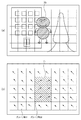
図7のステップS12での判定処理の第2の方法について、詳細に説明する。ここで、現フィールド画像が図9(a)に例示するものであって、画面中央部に人物である主被写体60が存在しているものとする。また、この現フィールド画像の画像データに対して顔検出部24で顔検出が行われ、検出された顔の位置が算出される。顔位置の算出結果を、図9(a)に顔検出枠61として太枠表示して示す。
<Second method of determination processing>
The second method of the determination process in step S12 of FIG. 7 will be described in detail. Here, it is assumed that the current field image is illustrated in FIG. 9A and that a main subject 60 that is a person exists in the center of the screen. Further, the
図9(b)は、図9(a)で示した現フィールド画像の各ベクトル検出領域について、動きベクトル検出部37で検出された動きベクトルの例を示す。図9(a)における主被写体60が背景に対して移動している場合、図9(b)に斜線を付して示す、主被写体60が含まれる主被写体領域62の動きベクトルは、画面内の他の領域の動きベクトルとは異なるものとなる。このとき、例えばX方向における動きベクトルの値に基づく度数分布は、図10のヒストグラムに例示するように、グループ#11およびグループ#12の2つ極値が存在する形となる。図9(b)を参照することで、グループ#12が主被写体領域62の動きベクトルに基づき、グループ#11が主被写体領域62以外、すなわち、背景領域における背景画像の動きベクトルに基づくことが分かる。
FIG. 9B shows an example of motion vectors detected by the motion
図9(b)の太枠で示す領域63は、図9(a)に示される顔検出枠61の内部を含むベクトル検出領域である。このうち、背景領域であるグループ#11に属するベクトル検出領域は2個であり、主被写体領域62であるグループ#12に属するベクトル検出領域は4個である。顔検出枠61の内部と共有する部分を持つベクトル検出領域の数が多い方が、主被写体領域である可能性が高いので、グループ#12が主被写体領域のグループであると判定することができる。
A
動きベクトル制御部32は、動きベクトル分類部30で求められた各グループの情報と、顔検出部24で検出された顔の位置情報とに基づき、主被写体領域のグループを特定する。すなわち、動きベクトル制御部32は、グループ#11およびグループ#12それぞれについて、各グループに含まれるベクトル検出領域と、顔検出枠61を含むベクトル検出領域との重複部分を検出する。そして、グループ#11およびグループ#12のうち、当該重複部分の大きい方を、主被写体領域のグループであると判定する。
The motion
以上のように、顔検出機能を利用することによって、動きベクトル分類部30にて検出されたグループが複数個存在し、且つ、主被写体が人である場合に、背景領域と主被写体領域の判別を容易に行うことができる。
As described above, by using the face detection function, when there are a plurality of groups detected by the motion
なお、上述では、背景に対して移動する被写体が1種類であるものとして説明したが、実際の撮影においては、背景に対して移動する被写体が複数存在することも有り得る。本第1の実施形態では、このような場合、画面内に存在する複数の被写体のうち、最も画面上に占める割合の大きい被写体を主たる被写体とし、他の被写体領域のベクトル検出値については処理の対象としない。つまり、背景に対して移動する被写体が画面内に複数、存在する場合でも、処理の対象となる被写体が1種類しか存在しないと見做すものとする。 In the above description, it is assumed that there is only one type of subject that moves relative to the background. However, in actual shooting, there may be a plurality of subjects that move relative to the background. In the first embodiment, in such a case, among the plurality of subjects existing in the screen, the subject having the largest proportion on the screen is set as the main subject, and the vector detection values of other subject areas are processed. Not targeted. That is, even when there are a plurality of subjects moving relative to the background in the screen, it is assumed that there is only one type of subject to be processed.
例えば、現フィールドの画像においてベクトル検出領域が3以上のグループに分類された場合、上述の判定処理の第1の方法では、ばらつき値Zが最も大きいグループを背景グループとし、背景グループ以外のグループを被写体グループとする。そして、複数の被写体グループについて、グループに含まれる階級における度数の総和を比較して、最も大きな値を得た被写体グループを処理の対象(処理する被写体グループ)とすることが考えられる。この場合、他の被写体グループ(第3のグループ)については処理対象としない。 For example, when the vector detection area is classified into three or more groups in the image of the current field, in the first method of the determination process described above, the group having the largest variation value Z is set as the background group, and groups other than the background group are set. A subject group. Then, for a plurality of subject groups, the sum of the frequencies in the classes included in the groups is compared, and the subject group that has obtained the largest value can be considered as the subject of processing (subject subject group to be processed). In this case, other subject groups (third group) are not processed.
また例えば、上述の判定処理の第2の方法では、顔領域を含むベクトル検出領域の数が最も少ないグループを背景グループとし、背景グループ以外のグループを被写体グループとする。そして、複数の被写体グループについて、グループに含まれる階級における度数の総和を比較して、最も大きな値を得た被写体グループを処理の対象(処理する被写体グループ)とすることが考えられる。この場合も、他の被写体グループ(第3のグループ)については処理対象としない。 Further, for example, in the second method of the determination process described above, a group having the smallest number of vector detection areas including the face area is set as a background group, and a group other than the background group is set as a subject group. Then, for a plurality of subject groups, the sum of the frequencies in the classes included in the groups is compared, and the subject group that has obtained the largest value can be considered as the subject of processing (subject subject group to be processed). Also in this case, the other subject group (third group) is not processed.
説明は図7のフローチャートに戻り、ステップS12で主被写体領域のグループが判定されたら、処理はステップS13に移行される。ステップS13では、ステップS12で主被写体領域であると判定されたグループ(主被写体グループと呼ぶ)に属するベクトル検出領域の数が、予め設定された閾値th0より大きいか否かの判定を行う。 Returning to the flowchart of FIG. 7, when the group of the main subject area is determined in step S12, the process proceeds to step S13. In step S13, (referred to as a main object group) and the determined group is the main object area in step S12 the number of vector detection areas belonging to the, it is determined whether or not a preset threshold value th 0 or greater than.
若し、主被写体グループに属するベクトル検出領域の数が閾値th0より大きいと判定されたら、処理はステップS14に移行される。ステップS14では、主被写体グループの代表動きベクトルを、全体動きベクトルとして採用する。 If it is determined that the number of vector detection areas belonging to the main subject group is greater than the threshold th 0 , the process proceeds to step S14. In step S14, the representative motion vector of the main subject group is adopted as the overall motion vector.
一方、ステップS13で、主被写体グループに属するベクトル検出領域の数が閾値th0よりも大きくない(閾値以下)と判定されたら、処理はステップS15に移行される。ステップS15では、背景領域によるグループ(以下、背景グループと呼ぶ)の代表動きベクトルを、全体動きベクトルとして採用する。そして、次のフィールド画像に対する処理が開始される(図示しない)。 On the other hand, if it is determined in step S13 that the number of vector detection areas belonging to the main subject group is not greater than the threshold th 0 (below the threshold), the process proceeds to step S15. In step S15, a representative motion vector of a group based on the background region (hereinafter referred to as a background group) is adopted as the overall motion vector. Then, processing for the next field image is started (not shown).
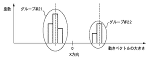
一例として、図11(a)に示すように、画面内に占める割合が比較的小さい主被写体70が現フィールド画像の中央部分に存在している場合について考える。この場合において、当該現フィールド画像における動きベクトル検出結果は、図11(b)に示されるように、画面の中央部分の6個のベクトル検出領域からなる領域71と、それ以外の領域とで異なっているものとする。当該動きベクトル検出結果による動きベクトルの値に基づく度数分布は、図12のヒストグラムに例示するように、背景領域によるグループ#21と、主被写体領域によるグループ#22との2つの極値が存在する形となる。
As an example, let us consider a case where a main subject 70 having a relatively small ratio in the screen is present in the center portion of the current field image, as shown in FIG. In this case, as shown in FIG. 11B, the motion vector detection result in the current field image differs between the
このような場合において、動きベクトル制御部32により、例えば主被写体領域によるグループ#22に属するベクトル検出領域の数が閾値th0以下であると判定され、背景領域であるグループ#21の動きベクトルを精度良く算出することができる。
In such a case, the
別の例として、図13(a)に示すように、画面内に占める割合が比較的大きい主被写体75が現フィールド画像の中央部分に存在している場合について考える。この図13(a)に示すように、主被写体の画面に占める割合が比較的大きいときは、撮影者が被写体を画面の中央に収めるように撮影していることが多い。そのため、背景領域の動きベクトル検出値を用いるよりも、主被写体領域のみの動きベクトル検出値を用いて、主被写体が画面内の元の位置に留まるように画像メモリの読み出し位置を変化させた方が、防振効果が高い映像を得ることができる。 As another example, as shown in FIG. 13A, consider a case where a main subject 75 having a relatively large proportion in the screen is present in the center portion of the current field image. As shown in FIG. 13A, when the ratio of the main subject to the screen is relatively large, the photographer often takes a picture so that the subject is placed in the center of the screen. Therefore, instead of using the motion vector detection value of the background area, the read position of the image memory is changed so that the main subject stays at the original position in the screen using the motion vector detection value of only the main subject area. However, it is possible to obtain an image with a high anti-vibration effect.
この場合において、当該現フィールド画像における動きベクトル検出結果は、図13(b)に示されるように、画面中央部分の26個のベクトル検出領域からなる領域76と、それ以外の領域とで異なっているものとする。当該動きベクトル検出結果による動きベクトルの値に基づく度数分布は、図14のヒストグラムに例示するように、背景領域によるグループ#31と、主被写体領域によるグループ#32の2つの極値が存在する形となる。
In this case, as shown in FIG. 13B, the motion vector detection result in the current field image differs between the
このような場合において、動きベクトル制御部32により、例えば主被写体領域によるグループ#32に属するベクトル検出領域の数が閾値th0より大きいと判定され、主被写体領域であるグループ#32の動きベクトルを精度良く算出することができる。
In such a case, for example, the motion
上述したように、本発明の第1の実施形態によれば、主被写体の画面に占める割合が比較的大きい場合であっても、背景領域と主被写体領域とを適切に検出することができ、精度の高い動きベクトル値を算出することが可能となる。 As described above, according to the first embodiment of the present invention, the background area and the main subject area can be appropriately detected even when the ratio of the main subject to the screen is relatively large. It becomes possible to calculate a motion vector value with high accuracy.
<第2の実施形態>
次に、本発明の第2の実施形態について説明する。本第2の実施形態では、過去、例えば1フィールド前の画像データにおいて、背景領域によるグループ(背景グループ)を全体動きベクトルを算出するグループとして選択したか否かを判定する。そして、この判定結果に基づき、全体動きベクトルを背景領域および主被写体領域の何れを用いて算出するかを判定する際の閾値を設定する。
<Second Embodiment>
Next, a second embodiment of the present invention will be described. In the second embodiment, it is determined whether or not a group (background group) based on the background region has been selected as a group for calculating the entire motion vector in the past, for example, image data one field before. Then, based on this determination result, a threshold for determining whether to calculate the entire motion vector using the background region or the main subject region is set.
なお、本第2の実施形態では、第1の実施形態で説明した撮像装置1および動きベクトル検出部14の構成をそのまま適用できる。また、動きベクトル検出部14における、フィルタ33から動きベクトル演算部31に至る処理も、第1の実施形態で説明した処理と同一であるので、ここでの説明を省略する。
In the second embodiment, the configurations of the
図15は、本第2の実施形態による全体動きベクトルの算出処理を示す一例のフローチャートである。図15のフローチャートにおける各処理は、システム制御部22の制御に従い動きベクトル制御部32により実行される。
FIG. 15 is a flowchart illustrating an example of the entire motion vector calculation process according to the second embodiment. Each process in the flowchart of FIG. 15 is executed by the motion
図15のフローチャートにおいて、ステップS20〜ステップS22の処理は、図7のフローチャートにおけるステップS10〜ステップS12の処理と同様である。すなわち、ステップS20で、動きベクトル制御部32は、動きベクトル分類部30が現在の画像データ、すなわち、現フィールドの画像データにおいて複数個のグループを検出したか否かを判定する。若し、検出されたグループが1つであると判定された場合は、処理はステップS21に移行され、検出されたグループの代表動きベクトルを全体動きベクトルとして採用する。そして、次のフィールド画像に対する処理が開始される(図示しない)。
In the flowchart in FIG. 15, the processes in steps S20 to S22 are the same as the processes in steps S10 to S12 in the flowchart in FIG. 7. That is, in step S20, the motion
一方、ステップS20で、動きベクトル分類部30にて検出されたグループが複数個存在すると判定された場合は、処理はステップS22に移行される。そして、図8〜図14を用いて説明した方法により、動きベクトル分類部30で検出された各グループが背景領域のベクトル検出領域によるものか、主被写体領域のベクトル検出領域によるものかの判定を行う。
On the other hand, if it is determined in step S20 that there are a plurality of groups detected by the motion
ステップS22での判定処理が終了すると、処理は次のステップS23に移行される。ステップS23では、過去の画像データにおいて、動きベクトル分類部30にて検出された複数個のグループのうち、背景グループを全体動きベクトルを算出するグループとして選択したか否かが判定される。過去の画像データは、例えば処理中の画像データに対して時間的に直前の、1フィールド前の画像データである。なお、過去の画像データにおいて、動きベクトル分類部30にて複数のグループが存在すると判定されていなかった場合は、背景グループを全体動きベクトルを算出するグループとして選択していたと見做す。
When the determination process in step S22 ends, the process proceeds to the next step S23. In step S23, it is determined whether or not the background group is selected as a group for calculating the entire motion vector among the plurality of groups detected by the motion
若し、ステップS23において、背景グループが選択されていたと判定された場合は、処理はステップS24に移行され、第1の値th1を、後述するステップS26で用いる閾値thに設定する。 If it is determined in step S23 that the background group has been selected, the process proceeds to step S24, and the first value th 1 is set to a threshold th used in step S26 described later.
一方、ステップS23において、背景グループが選択されていなかった、すなわち、主被写体グループが選択されていたと判定された場合は、処理はステップS25に移行される。ステップS25では、第1の値th1より小さい第2の値th2を、後述するステップS26で用いる閾値thに設定する。 On the other hand, if it is determined in step S23 that the background group has not been selected, that is, the main subject group has been selected, the process proceeds to step S25. In step S25, a second value th 2 smaller than the first value th 1 is set as a threshold th used in step S26 described later.
ステップS24またはステップS25で閾値thが設定されると、処理はステップS26に移行される。ステップS26では、ステップS22で主被写体領域であると判定された主被写体グループに属するベクトル検出領域の数が、ステップS24またはステップS25で設定された閾値thより大きいか否かの判定を行う。 When the threshold value th is set in step S24 or step S25, the process proceeds to step S26. In step S26, it is determined whether or not the number of vector detection regions belonging to the main subject group determined to be the main subject region in step S22 is greater than the threshold th set in step S24 or step S25.
若し、主被写体グループに属するベクトル検出領域の数が閾値thより大きいと判定されたら、処理はステップS27に移行される。ステップS27で、動きベクトル制御部32は、主被写体グループの代表動きベクトルを画面全体の動きベクトルとして採用する。
If it is determined that the number of vector detection areas belonging to the main subject group is greater than the threshold th, the process proceeds to step S27. In step S27, the motion
一方、ステップS26で、主被写体グループに属するベクトル検出領域の数が閾値thよりも大きくないと判定されたら、処理はステップS28に移行される。ステップS28では、背景グループの代表動きベクトルを全体動きベクトルとして採用する。そして、次のフィールド画像に対する処理が開始される(図示しない)。 On the other hand, if it is determined in step S26 that the number of vector detection areas belonging to the main subject group is not greater than the threshold th, the process proceeds to step S28. In step S28, the representative motion vector of the background group is adopted as the overall motion vector. Then, processing for the next field image is started (not shown).
本第2の実施形態では、上述したステップS24またはステップS25において閾値thに設定するための第1の値th1および第2の値th2の関係を、第1の値th1>第2の値th2となるようにしている。 In the second embodiment, the relationship between the first value th 1 and the second value th 2 for setting the threshold value th in step S24 or step S25 described above is as follows: first value th 1 > second The value th 2 is set.
これにより、過去の画像データにおいて背景グループを選択している場合に、現在の画像データでも背景グループが選択され易くなる。そして、主被写体領域に属する動きベクトル検出領域の数が閾値th1を一旦超え、主被写体グループが選択されたら、閾値thが閾値th1より小さい値の閾値th2に変更される。これにより、主被写体グループが選択され易い状態となる。 Thereby, when the background group is selected in the past image data, the background group is easily selected even in the current image data. When the number of motion vector detection areas belonging to the main subject area once exceeds the threshold th 1 and a main subject group is selected, the threshold th is changed to a threshold th 2 having a value smaller than the threshold th 1 . As a result, the main subject group is easily selected.
したがって、全体動きベクトルとして用いるグループが主被写体グループと背景グループとで頻繁に切り替わるのが抑制される。そのため、例えば主被写体領域と背景領域とでベクトル検出領域の数の差が小さい場合に、違和感のある映像になることを防止することができる。 Therefore, frequent switching of the group used as the overall motion vector between the main subject group and the background group is suppressed. For this reason, for example, when the difference in the number of vector detection areas between the main subject area and the background area is small, it is possible to prevent an uncomfortable image.
<第3の実施形態>
次に、本発明の第3の実施形態について説明する。本第3の実施形態では、背景グループの代表動きベクトルと、主被写体領域のグループの代表動きベクトルとを、所定の割合で合成して、全体動きベクトルを生成する。
<Third Embodiment>
Next, a third embodiment of the present invention will be described. In the third embodiment, the representative motion vector of the background group and the representative motion vector of the group of the main subject area are combined at a predetermined ratio to generate an overall motion vector.
なお、本第3の実施形態では、第1の実施形態で説明した撮像装置1および動きベクトル検出部14の構成をそのまま適用できる。また、動きベクトル検出部14における、フィルタ33から動きベクトル演算部31に至る処理も、第1の実施形態で説明した処理と同一であるので、ここでの説明を省略する。
In the third embodiment, the configurations of the
図16は、本第3の実施形態による全体動きベクトルの算出処理を示す一例のフローチャートである。図16のフローチャートにおける各処理は、システム制御部22の制御に従い動きベクトル制御部32により実効される。
FIG. 16 is a flowchart illustrating an example of the entire motion vector calculation process according to the third embodiment. Each process in the flowchart of FIG. 16 is executed by the motion
図16のフローチャートにおいて、ステップS30〜ステップS33の処理は、図7のフローチャートにおけるステップS10〜ステップS13の処理と同様である。すなわち、ステップS30で、動きベクトル制御部32は、動きベクトル分類部30が現在の画像データ、すなわち、現フィールドの画像データにおいて複数個のグループを検出したか否かを判定する。
In the flowchart in FIG. 16, the processes in steps S30 to S33 are the same as the processes in steps S10 to S13 in the flowchart in FIG. 7. That is, in step S30, the motion
若し、検出されたグループが1つであると判定された場合は、処理はステップS31に移行され、検出されたグループの代表動きベクトルを全体動きベクトルとして採用する。そして、次のフィールド画像に対する処理が開始される(図示しない)。 If it is determined that there is one detected group, the process proceeds to step S31, and the representative motion vector of the detected group is adopted as the overall motion vector. Then, processing for the next field image is started (not shown).
一方、ステップS30で、動きベクトル分類部30にて検出されたグループが複数個存在すると判定された場合は、処理はステップS32に移行される。そして、図8〜図14を用いて説明した方法により、動きベクトル分類部30で検出された各グループが背景領域のベクトル検出領域によるものか、主被写体領域のベクトル検出領域によるものかの判定を行う。
On the other hand, when it is determined in step S30 that there are a plurality of groups detected by the motion
若し、ステップS32で主被写体領域によるグループであると判定されたら、処理はステップS33に移行される。ステップS33では、ステップS32で主被写体領域によるグループである判定された主被写体グループに属するベクトル検出領域の数が、閾値th0より大きいか否かの判定を行う。 If it is determined in step S32 that the group is based on the main subject area, the process proceeds to step S33. In step S33, the number of the determined vector detection areas belonging to the main subject groups were a group by the main object region in step S32 is, it is determined whether the threshold value th 0 or greater than.
若し、主被写体グループに属するベクトル検出領域の数が閾値th0より大きいと判定されたら、処理はステップS34に移行される。ステップS34では、動きベクトル制御部32は、後述するステップS36で用いる変数MIX_RATEに例えば1を加算し、変数MIX_RATEをインクリメント(増加)させる。但し、変数MIX_RATEが上限値MIX_RATE_MAXに達したら、インクリメントは行わない。変数MIX_RATEは、例えば動きベクトル制御部32が持つレジスタなどに保持される。
If it is determined that the number of vector detection areas belonging to the main subject group is greater than the threshold th 0 , the process proceeds to step
一方、ステップS33で、主被写体グループに属するベクトル検出領域の数が閾値th0よりも大きくないと判定されたら、処理はステップS35に移行される。ステップS35では、動きベクトル制御部32は、変数MIX_RATEから例えば1を減じ、変数MIX_RATEをデクリメント(減少)させる。但し、変数MIX_RATEが下限値0に達したら、デクリメントは行わない。
On the other hand, in step S33, When the number of vector detection areas belonging to the main object group is not greater than the threshold value th 0, the process proceeds to step S35. In step S35, the motion
ステップS34またはステップS35の処理が終了したら、処理はステップS36に移行される。ステップS36では、全体動きベクトルFINAL_VECTORを下記に示す式(4)により算出する。なお、式(4)において、値BACK_VECTORは、背景グループの代表動きベクトルであり、値TARGET_VECTORは、主被写体領域のグループの代表動きベクトルである。
FINAL_VECTOR=BACK_VECTOR×(MIX_RATE_MAX−MIX_RATE)/MIX_RATE_MAX+TARGET_VECTOR×MIX_RATE/MIX_RATE_MAX …(4)
When the process of step S34 or step S35 is completed, the process proceeds to step S36. In step S36, the entire motion vector FINAL_VECTOR is calculated by the following equation (4). In equation (4), the value BACK_VECTOR is the representative motion vector of the background group, and the value TARGET_VECTOR is the representative motion vector of the group of the main subject area.
FINAL_VECTOR = BACK_VECTOR × (MIX_RATE_MAX−MIX_RATE) / MIX_RATE_MAX + TARGET_VECTOR × MIX_RATE / MIX_RATE_MAX (4)
ステップS36で式(4)により全体動きベクトルが算出されると、次のフィールド画像に対する処理が開始される(図示しない)。変数MIX_RATEは保持され、当該次のフィールド画像に対する処理の際のステップS34またはステップS35で、インクリメントまたはデクリメントされる。 When the entire motion vector is calculated by equation (4) in step S36, processing for the next field image is started (not shown). The variable MIX_RATE is held, and is incremented or decremented in step S34 or step S35 in the process for the next field image.
ここで、式(4)において、変数MIX_RATEは、上限値MIX_RATE_MAXを100%としたときの、全体動きベクトルFINAL_VECTORにおける主被写体領域の動きベクトルの割合を示す。したがって、式(4)内の式(MIX_RATE_MAX−MIX_RATE)は、全体動きベクトルFINAL_VECTORのうちの背景領域の動きベクトルの割合を示す値となる。 Here, in Expression (4), the variable MIX_RATE indicates the ratio of the motion vector of the main subject area in the overall motion vector FINAL_VECTOR when the upper limit value MIX_RATE_MAX is 100%. Therefore, the equation (MIX_RATE_MAX−MIX_RATE) in the equation (4) is a value indicating the ratio of the motion vector of the background area in the entire motion vector FINAL_VECTOR.
すなわち、本第3の実施形態においては、全体動きベクトルとして用いる代表動きベクトルを、主被写体グループと背景グループとで切り替える際に、主被写体領域および背景領域の動きベクトルの混合割合を徐々に入れ替えている。例えば、主被写体領域と背景領域とでベクトル検出領域の数の差が小さい場合には、全体動きベクトルとして用いるグループが主被写体領域と背景領域とで頻繁に切り替わると考えられる。このような場合には、主被写体領域および背景領域の代表動きベクトルが略等しい割合で用られ、全体動きベクトルが生成される。 That is, in the third embodiment, when the representative motion vector used as the overall motion vector is switched between the main subject group and the background group, the mixing ratio of the motion vectors of the main subject region and the background region is gradually switched. Yes. For example, when the difference in the number of vector detection regions between the main subject region and the background region is small, it is considered that the group used as the entire motion vector is frequently switched between the main subject region and the background region. In such a case, the representative motion vectors of the main subject area and the background area are used at a substantially equal ratio, and an overall motion vector is generated.
これにより、全体動きベクトルとして用いるグループの主被写体グループから背景グループとの間での切り替わりが急激に生じるのが抑制され、違和感のある映像になることを防止することができる。 Thereby, it is possible to suppress a sudden switching between the main subject group and the background group of the group used as the entire motion vector, and to prevent the image from being uncomfortable.
<第3の実施形態の変形例>
次に、第3の実施形態の変形例について説明する。本変形例は、第3の実施形態に対して、上述した第2の実施形態による処理を組み合わせたものである。図17は、本第3の実施形態の変形例による全体動きベクトルの算出処理を示す一例のフローチャートである。図17のフローチャートにおける各処理は、システム制御部22の制御に従い動きベクトル制御部32により実行される。なお、図17のフローチャートにおいて、上述した図15および図16のフローチャートと共通する処理には同一の符号を付し、詳細な説明を省略する。
<Modification of Third Embodiment>
Next, a modification of the third embodiment will be described. This modification is a combination of the processing according to the second embodiment described above with respect to the third embodiment. FIG. 17 is a flowchart illustrating an example of the calculation process of the entire motion vector according to the modification of the third embodiment. Each process in the flowchart of FIG. 17 is executed by the motion
ステップS20で、動きベクトル制御部32は、動きベクトル分類部30が現在の画像データにおいて複数個のグループを検出したか否かを判定する。若し、検出されたグループが1つであると判定された場合は、処理はステップS21に移行され、検出されたグループの代表動きベクトルを全体動きベクトルとして採用する。そして、次のフィールド画像に対する処理が開始される(図示しない)。
In step S20, the motion
一方、ステップS20で、動きベクトル分類部30にて検出されたグループが複数個存在すると判定された場合は、処理はステップS22に移行される。そして、図8〜図14を用いて説明した方法により、動きベクトル分類部30で検出された各グループが背景領域のベクトル検出領域によるものか、主被写体領域のベクトル検出領域によるものかの判定を行う。
On the other hand, if it is determined in step S20 that there are a plurality of groups detected by the motion
ステップS22での判定処理が終了すると、処理は次のステップS23に移行される。ステップS23では、過去の画像データにおいて、動きベクトル分類部30にて検出された複数個のグループのうち、背景グループを全体動きベクトルを算出するグループとして選択したか否かが判定される。
When the determination process in step S22 ends, the process proceeds to the next step S23. In step S23, it is determined whether or not the background group is selected as a group for calculating the entire motion vector among the plurality of groups detected by the motion
若し、ステップS23において、背景グループが選択されていたと判定された場合は、処理はステップS24に移行され、第1の値th1を、後述するステップS26で用いる閾値thに設定する。一方、ステップS23において、背景グループが選択されていなかったと判定された場合は、処理はステップS25に移行され、第1の値th1より小さい第2の値th2を、後述するステップS26で用いる閾値thに設定する。 If it is determined in step S23 that the background group has been selected, the process proceeds to step S24, and the first value th 1 is set to a threshold th used in step S26 described later. On the other hand, if it is determined in step S23 that the background group has not been selected, the process proceeds to step S25, and a second value th 2 smaller than the first value th 1 is used in step S26 described later. Set to threshold th.
処理はステップS26に移行され、ステップS22で主被写体領域であると判定された主被写体グループに属するベクトル検出領域の数が、ステップS24またはステップS25で設定された閾値thより大きいか否かの判定を行う。 The process proceeds to step S26, and it is determined whether or not the number of vector detection regions belonging to the main subject group determined to be the main subject region in step S22 is greater than the threshold th set in step S24 or step S25. I do.
若し、主被写体グループに属するベクトル検出領域の数が閾値thより大きいと判定されたら、処理はステップS34に移行され、変数MIX_RATEをインクリメントする。但し、変数MIX_RATEが上限値MIX_RATE_MAXに達したら、インクリメントは行わない。一方、ステップS26で、主被写体グループに属するベクトル検出領域の数が閾値thよりも大きくないと判定されたら、処理はステップS35に移行され、変数MIX_RATEをデクリメントする。但し、変数MIX_RATEが下限値MIX_RATE_MINに達したら、デクリメントは行わない。 If it is determined that the number of vector detection regions belonging to the main subject group is greater than the threshold th, the process proceeds to step S34, and the variable MIX_RATE is incremented. However, when the variable MIX_RATE reaches the upper limit value MIX_RATE_MAX, the increment is not performed. On the other hand, if it is determined in step S26 that the number of vector detection areas belonging to the main subject group is not greater than the threshold th, the process proceeds to step S35, and the variable MIX_RATE is decremented. However, when the variable MIX_RATE reaches the lower limit MIX_RATE_MIN, no decrement is performed.
ステップS34またはステップS35の処理が終了したら、処理はステップS36に移行され、全体動きベクトルFINAL_VECTORを上述した式(4)により算出する。全体動きベクトルが算出されると、次のフィールド画像に対する処理が開始される(図示しない)。 When the process of step S34 or step S35 is completed, the process proceeds to step S36, and the overall motion vector FINAL_VECTOR is calculated by the above-described equation (4). When the entire motion vector is calculated, processing for the next field image is started (not shown).
<第4の実施形態>
次に、本発明の実施の第4の形態について説明する。本第4の実施形態では、全体動きベクトルとして用いる代表動きベクトルを、上述した第1および第2の実施形態による判定処理と、主被写体領域および背景領域の代表動きベクトルの差が所定値以内であるか否かの判定処理とを組み合わせた判定により選択する。
<Fourth Embodiment>
Next, a fourth embodiment of the present invention will be described. In the fourth embodiment, the representative motion vector used as the entire motion vector is determined so that the difference between the determination processing according to the first and second embodiments described above and the representative motion vector of the main subject area and the background area is within a predetermined value. The selection is made by a combination of the determination process of whether or not there is.
図18は、本第4の実施形態による全体動きベクトルの算出処理を示す一例のフローチャートである。図18のフローチャートにおける各処理は、システム制御部22の制御に従い動きベクトル制御部32により実行される。
FIG. 18 is a flowchart illustrating an example of the entire motion vector calculation process according to the fourth embodiment. Each process in the flowchart of FIG. 18 is executed by the motion
図18のフローチャートにおいて、ステップS40〜ステップS43の処理は、図15のフローチャートにおけるステップS20〜ステップS23の処理と同様である。すなわち、ステップS40で、動きベクトル制御部32は、動きベクトル分類部30が現在の画像データ、すなわち、現フィールドの画像データにおいて複数個のグループを検出したか否かを判定する。若し、検出されたグループが1つであると判定された場合は、処理はステップS41に移行され、検出されたグループの代表動きベクトルを画面全体すなわち画像全体の動きベクトルとして採用する。そして、次のフィールド画像に対する処理が開始される(図示しない)。
In the flowchart in FIG. 18, the processes in steps S40 to S43 are the same as the processes in steps S20 to S23 in the flowchart in FIG. 15. That is, in step S40, the motion
一方、ステップS40で、動きベクトル分類部30にて検出されたグループが複数個存在すると判定された場合は、処理はステップS42に移行される。そして、図8〜図14を用いて説明した方法により、動きベクトル分類部30で検出された各グループが背景領域のベクトル検出領域によるものか、主被写体領域のベクトル検出領域によるものかの判定を行う。
On the other hand, if it is determined in step S40 that there are a plurality of groups detected by the motion
ステップS42での判定処理が終了すると、処理は次のステップS43に移行される。ステップS43では、過去、例えば1フィールド前の画像データにおいて、動きベクトル分類部30にて検出された複数個のグループのうち、背景グループを全体動きベクトルを算出するグループとして選択したか否かが判定される。なお、過去の画像データにおいて、動きベクトル分類部30にて複数のグループが存在すると判定されていなかった場合は、背景グループを全体動きベクトルを算出するグループとして選択していたとみなす。
When the determination process in step S42 ends, the process proceeds to the next step S43. In step S43, it is determined whether or not a background group has been selected as a group for calculating an overall motion vector among a plurality of groups detected by the motion
若し、ステップS43において、背景グループが選択されていたと判定された場合は、処理はステップS44に移行され、フラグBACK_FLAGがセットされる。一方、ステップS43において、背景グループが選択されていなかった、すなわち、主被写体グループが選択されていたと判定された場合は、処理はステップS45に移行され、フラグBACK_FLAGがリセットされる。フラグBACK_FLAGは、例えば動きベクトル制御部32が持つレジスタなどに保持される。
If it is determined in step S43 that the background group has been selected, the process proceeds to step S44, and the flag BACK_FLAG is set. On the other hand, if it is determined in step S43 that the background group has not been selected, that is, the main subject group has been selected, the process proceeds to step S45, and the flag BACK_FLAG is reset. The flag BACK_FLAG is held in, for example, a register included in the motion
ステップS44またはステップS45でフラグBACK_FLAGの設定が行われたら、処理はステップS46に移行される。ステップS46では、差分算出手段としての動きベクトル制御部32で背景領域の代表動きベクトルと主被写体領域の代表動きベクトルとの差分が求められる。そして、この差分が所定値以内であるか否かが判定される。このステップS46の判定は、換言すれば、主被写体の画面上での移動速度が所定速度以下であるか否かの判定となる。
If the flag BACK_FLAG is set in step S44 or step S45, the process proceeds to step S46. In step S46, the difference between the representative motion vector of the background area and the representative motion vector of the main subject area is obtained by the motion
若し、ステップS46において、背景領域および主被写体領域の代表動きベクトルの差分が所定値以内であると判定されたら、処理はステップS47に移行され、フラグCHANGE_FLAGがセットされる。これは、主被写体の画面上での移動速度が所定速度よりも小さい場合である。フラグCHANGE_FLAGは、例えば動きベクトル制御部32が持つレジスタなどに保持される。
If it is determined in step S46 that the difference between the representative motion vectors of the background area and the main subject area is within a predetermined value, the process proceeds to step S47 and the flag CHANGE_FLAG is set. This is a case where the moving speed of the main subject on the screen is smaller than a predetermined speed. The flag CHANGE_FLAG is held in, for example, a register included in the motion
一方、ステップS46において、背景領域および主被写体領域の代表動きベクトルの差分が所定値より大きいと判定されたら、処理はステップS48に移行され、フラグCHANGE_FLAGがリセットされる。これは、主被写体の画面上での移動速度が所定速度より大きい場合である。 On the other hand, if it is determined in step S46 that the difference between the representative motion vectors of the background area and the main subject area is greater than the predetermined value, the process proceeds to step S48, and the flag CHANGE_FLAG is reset. This is a case where the moving speed of the main subject on the screen is larger than a predetermined speed.
ステップS47またはステップS48でのフラグCHANGE_FLAGの設定が行われたら、処理はステップS49に移行される。ステップS49では、上述したステップS42で主被写体領域であると判定された主被写体グループに属するベクトル検出領域の数が、予め設定された閾値th0より大きいか否かの判定を行う。 If the flag CHANGE_FLAG is set in step S47 or step S48, the process proceeds to step S49. At step S49, the number of vector detection areas belonging to the main object group is determined in step S42 described above as the main subject area, performs whether advance greater than the set threshold value th 0 determination.
若し、ステップS49で、主被写体グループに属するベクトル検出領域の数が閾値th0よりも大きいと判定されたら、処理はステップS50に移行される。ステップS50では、後述する第1のグループ選択により全体動きベクトルに用いる代表動きベクトルが選択される。 If it is determined in step S49 that the number of vector detection regions belonging to the main subject group is larger than the threshold th 0 , the process proceeds to step S50. In step S50, a representative motion vector used for the entire motion vector is selected by a first group selection described later.
一方、ステップS49で、主被写体グループに属するベクトル検出領域の数が閾値th0よりも大きくないと判定されたら、処理はステップS51に移行される。ステップS51では、後述する第2のグループ選択により全体動きベクトルに用いる代表動きベクトルが選択される。 On the other hand, if it is determined in step S49 that the number of vector detection areas belonging to the main subject group is not greater than the threshold th 0 , the process proceeds to step S51. In step S51, a representative motion vector used for the entire motion vector is selected by a second group selection described later.
ステップS50またはステップS51で全体動きベクトルとして用いる代表動きベクトルが選択されたら、次のフィールド画像に対する処理が開始される(図示しない)。 When the representative motion vector used as the entire motion vector is selected in step S50 or step S51, processing for the next field image is started (not shown).
図19は、上述したステップS50による第1のグループ選択の一例の処理を示すフローチャートである。先ず、ステップS60において、フラグBACK_FLAGがリセットされているか否かが判定される。すなわち、ステップS60では、過去の画像データにおいて、主被写体グループの代表動きベクトルが全体動きベクトルとして選択されていたかどうかが判定される。若し、フラグBACK_FLAGがリセットされていたと判定されたら、処理はステップS61に移行される。これは、過去の画像データにおいて、主被写体グループの代表動きベクトルが全体動きベクトルとして選択されていた場合である。ステップS61では、主被写体グループの代表動きベクトルを全体動きベクトルとして採用する。 FIG. 19 is a flowchart showing an example of the first group selection process in step S50 described above. First, in step S60, it is determined whether or not the flag BACK_FLAG has been reset. That is, in step S60, it is determined whether or not the representative motion vector of the main subject group has been selected as the entire motion vector in the past image data. If it is determined that the flag BACK_FLAG has been reset, the process proceeds to step S61. This is a case where the representative motion vector of the main subject group has been selected as the overall motion vector in the past image data. In step S61, the representative motion vector of the main subject group is adopted as the overall motion vector.
一方、ステップS60において、フラグBACK_FLAGがリセットされていないと判定されたら、処理はステップS62に移行される。これは、過去の画像データにおいて、背景領域の代表動きベクトルが全体動きベクトルとして選択されていた場合である。ステップS62では、フラグCHANGE_FLAGがセットされているか否かが判定される。すなわち、ステップS62では、主被写体の画面上での移動速度が所定速度以下か否かが判定される。 On the other hand, if it is determined in step S60 that the flag BACK_FLAG has not been reset, the process proceeds to step S62. This is a case where the representative motion vector of the background area has been selected as the entire motion vector in the past image data. In step S62, it is determined whether or not the flag CHANGE_FLAG is set. That is, in step S62, it is determined whether or not the moving speed of the main subject on the screen is equal to or lower than a predetermined speed.
若し、ステップS62において、フラグCHANGE_FLAGがセットされていると判定されたら、処理はステップS63に移行される。これは、主被写体の画面上での移動速度が所定速度以下であった場合である。ステップS63では、主被写体グループの代表動きベクトルを、全体動きベクトルとして採用する。 If it is determined in step S62 that the flag CHANGE_FLAG is set, the process proceeds to step S63. This is a case where the moving speed of the main subject on the screen is equal to or lower than a predetermined speed. In step S63, the representative motion vector of the main subject group is adopted as the overall motion vector.
一方、ステップS62において、フラグCHANGE_FLAGがセットされていないと判定されたら、処理はステップS64に移行される。これは、主被写体の画面上での移動速度が所定速度より大きい場合である。ステップS64では、背景グループの代表動きベクトルを、全体動きベクトルとして採用する。 On the other hand, if it is determined in step S62 that the flag CHANGE_FLAG is not set, the process proceeds to step S64. This is a case where the moving speed of the main subject on the screen is larger than a predetermined speed. In step S64, the representative motion vector of the background group is adopted as the overall motion vector.
ステップS61、ステップS63またはステップS64により、全体動きベクトルとして用いる代表動きベクトルが決定されたら、処理は図19のフローチャートを抜け、図18のフローチャートに戻される。 When the representative motion vector used as the entire motion vector is determined in step S61, step S63, or step S64, the process exits the flowchart of FIG. 19 and returns to the flowchart of FIG.
図20は、上述したステップS51による第2のグループ選択の一例の処理を示すフローチャートである。先ず、ステップS70において、フラグBACK_FLAGがセットされているか否かが判定される。すなわち、ステップS70では、過去の画像データにおいて、背景グループの代表動きベクトルが全体動きベクトルとして選択されていたかどうかが判定される。若し、フラグBACK_FLAGがセットされていたと判定されたら、処理はステップS71に移行される。これは、過去の画像データにおいて、背景グループの代表動きベクトルが全体動きベクトルとして選択されていた場合である。ステップS71では、背景グループの代表動きベクトルを全体動きベクトルとして採用する。 FIG. 20 is a flowchart showing an example of the second group selection process in step S51 described above. First, in step S70, it is determined whether or not the flag BACK_FLAG is set. That is, in step S70, it is determined whether the representative group motion vector of the background group has been selected as the entire motion vector in the past image data. If it is determined that the flag BACK_FLAG has been set, the process proceeds to step S71. This is a case where the representative motion vector of the background group has been selected as the entire motion vector in the past image data. In step S71, the representative motion vector of the background group is adopted as the overall motion vector.
一方、ステップS70において、フラグBACK_FLAGがセットされていないと判定されたら、処理はステップS72に移行される。これは、過去の画像データにおいて、主被写体領域の代表動きベクトルが全体動きベクトルとして選択されていた場合である。ステップS72では、フラグCHANGE_FLAGがセットされているか否かが判定される。すなわち、ステップS72では、主被写体の画面上での移動速度が所定速度以下か否かが判定される。 On the other hand, if it is determined in step S70 that the flag BACK_FLAG is not set, the process proceeds to step S72. This is a case where the representative motion vector of the main subject region has been selected as the entire motion vector in the past image data. In step S72, it is determined whether or not the flag CHANGE_FLAG is set. That is, in step S72, it is determined whether or not the moving speed of the main subject on the screen is equal to or lower than a predetermined speed.
若し、ステップS72において、フラグCHANGE_FLAGがセットされていると判定されたら、処理はステップS73に移行される。これは、主被写体の画面上での移動速度が所定速度以下であった場合である。ステップS73では、背景グループの代表動きベクトルを、全体動きベクトルとして採用する。 If it is determined in step S72 that the flag CHANGE_FLAG is set, the process proceeds to step S73. This is a case where the moving speed of the main subject on the screen is equal to or lower than a predetermined speed. In step S73, the representative motion vector of the background group is adopted as the overall motion vector.
一方、ステップS72において、フラグCHANGE_FLAGがセットされていないと判定されたら、処理はステップS74に移行される。これは、主被写体の画面上での移動速度が所定速度より大きい場合である。ステップS74では、主被写体のグループの代表動きベクトルを、全体動きベクトルとして採用する。 On the other hand, if it is determined in step S72 that the flag CHANGE_FLAG is not set, the process proceeds to step S74. This is a case where the moving speed of the main subject on the screen is larger than a predetermined speed. In step S74, the representative motion vector of the main subject group is adopted as the overall motion vector.
ステップS71、ステップS73またはステップS74により、全体動きベクトルとして用いる代表動きベクトルが決定されたら、処理は図20のフローチャートを抜け、図18のフローチャートに戻される。 When the representative motion vector used as the overall motion vector is determined in step S71, step S73, or step S74, the process exits the flowchart of FIG. 20 and returns to the flowchart of FIG.
上述の図18〜図20のフローチャートによる全体動きベクトルの算出処理を要約すると、下記のようになる。 The overall motion vector calculation process according to the flowcharts of FIGS. 18 to 20 is summarized as follows.
先ず、主被写体グループに属するベクトル検出領域の数が閾値th0より多い場合には、下記のようになる。
(1)過去の画像データにおいて主被写体グループの代表動きベクトルが全体動きベクトルとして選択されていた場合、主被写体の画面上での移動速度に関わらず、主被写体グループの代表動きベクトルを全体動きベクトルとして採用する。
(2)過去の画像データにおいて背景グループの代表動きベクトルが全体動きベクトルとして選択されていた場合、若し、主被写体の動きが所定速度よりも速ければ、背景グループの代表動きベクトルを全体動きベクトルとして採用する。一方、主被写体の動きが所定速度よりも遅ければ、主被写体グループの代表動きベクトルを全体動きベクトルとして採用する。
First, when the number of vector detection areas belonging to the main subject group is larger than the threshold th 0 , the following is performed.
(1) When the representative motion vector of the main subject group is selected as the overall motion vector in the past image data, the representative motion vector of the main subject group is used as the overall motion vector regardless of the moving speed of the main subject on the screen. Adopt as.
(2) When the representative motion vector of the background group is selected as the overall motion vector in the past image data, if the motion of the main subject is faster than the predetermined speed, the representative motion vector of the background group is set to the overall motion vector. Adopt as. On the other hand, if the motion of the main subject is slower than the predetermined speed, the representative motion vector of the main subject group is adopted as the overall motion vector.
次に、主被写体グループに属するベクトル検出領域の数が閾値th0以下の場合には、下記のようになる。
(1)過去の画像データにおいて主被写体グループの代表動きベクトルが全体動きベクトルとして選択されていた場合、若し、主被写体の動きが所定速度よりも速ければ、主被写体グループの代表動きベクトルを全体動きベクトルとして採用する。一方、主被写体の動きが所定速度よりも遅ければ、背景グループの代表動きベクトルを全体動きベクトルとして採用する。
(2)過去の画像データにおいて背景グループの代表動きベクトルが全体動きベクトルとして選択されていた場合、主被写体の画面上での移動速度に関わらず、背景グループの代表動きベクトルを全体動きベクトルとして採用する。
Next, when the number of vector detection areas belonging to the main subject group is equal to or less than the threshold th 0, the following is performed.
(1) When the representative motion vector of the main subject group is selected as the overall motion vector in the past image data, if the motion of the main subject is faster than the predetermined speed, the representative motion vector of the main subject group is Adopt as a motion vector. On the other hand, if the motion of the main subject is slower than the predetermined speed, the representative motion vector of the background group is adopted as the overall motion vector.
(2) When the representative motion vector of the background group is selected as the overall motion vector in the past image data, the representative motion vector of the background group is adopted as the overall motion vector regardless of the moving speed of the main subject on the screen. To do.
以上の処理によって、全体動きベクトルとして用いる代表動きベクトルを、主被写体グループによる代表動きベクトルと背景グループによる代表動きベクトルとの間で切り換える処理を、主被写体の動きが小さいときに行うようにした。これによって、全体動きベクトルとして用いる代表動きベクトルの、主被写体グループと背景グループとの間での切り替わりが生じたときに、今まで防振されていた領域が急激に動きだすといった現象が生じることを防止することができる。 Through the above processing, the process of switching the representative motion vector used as the overall motion vector between the representative motion vector of the main subject group and the representative motion vector of the background group is performed when the main subject has a small motion. This prevents a phenomenon in which the area that was previously anti-vibrated starts to move suddenly when the representative motion vector used as the overall motion vector is switched between the main subject group and the background group. can do.
<第4の実施形態の変形例>
上述した第4の実施形態の変形例について説明する。本変形例は、上述した第4の実施形態による図18のフローチャートに対して、さらに上述の第2の実施形態による図15のフローチャートのステップS24およびステップS25の処理を追加し、ステップS49の処理をステップS26の処理と入れ替えたものである。すなわち、本変形例は、上述の第4の実施形態に対して、過去の画像データにおいて背景グループの代表動きベクトルを全体動きベクトルとして選択したか否かに応じて閾値thの設定を行う処理を追加して行う。
<Modification of Fourth Embodiment>
A modification of the above-described fourth embodiment will be described. In this modification, steps S24 and S25 of the flowchart of FIG. 15 according to the second embodiment described above are further added to the flowchart of FIG. 18 according to the fourth embodiment described above, and the process of step S49 is performed. Is replaced with the process of step S26. In other words, the present modification is a process for setting the threshold th according to whether or not the representative motion vector of the background group has been selected as the overall motion vector in the past image data, in the fourth embodiment described above. Add and do.
図21は、本変形例による全体動きベクトルの算出処理を示す一例のフローチャートである。図21のフローチャートにおける各処理は、システム制御部22の制御に従い動きベクトル制御部32により実行される。なお、図21のフローチャートにおいて、上述した図18のフローチャートと共通する処理には同一の符号を付し、詳細な説明を省略する。
FIG. 21 is a flowchart of an example illustrating the calculation process of the entire motion vector according to the present modification. Each process in the flowchart of FIG. 21 is executed by the motion
図21のフローチャートにおいて、先ず、ステップS40で、動きベクトル制御部32は、動きベクトル分類部30が現在の画像データにおいて複数個のグループを検出したか否かを判定する。若し、検出されたグループが1つであると判定された場合は、処理はステップS41に移行され、検出されたグループの代表動きベクトルを全体動きベクトルとして採用し、次のフィールド画像に対する処理が開始される(図示しない)。
In the flowchart of FIG. 21, first, in step S40, the motion
一方、ステップS40で、動きベクトル分類部30にて検出されたグループが複数個存在すると判定された場合は、処理はステップS42に移行される。そして、図8〜図14を用いて説明した方法により、動きベクトル分類部30で検出された各グループが背景領域のベクトル検出領域によるものか、被写体領域のベクトル検出領域によるものかの判定を行う。
On the other hand, if it is determined in step S40 that there are a plurality of groups detected by the motion
ステップS42での判定処理が終了すると、処理は次のステップS43に移行される。ステップS43では、過去、例えば1フィールド前の画像データにおいて、動きベクトル分類部30にて検出された複数個のグループのうち、背景グループの代表動きベクトルを全体動きベクトルとして選択したか否かが判定される。
When the determination process in step S42 ends, the process proceeds to the next step S43. In step S43, it is determined whether or not the representative motion vector of the background group has been selected as the entire motion vector among the plurality of groups detected by the motion
若し、ステップS43において、背景グループが選択されていたと判定された場合は、処理はステップS24に移行され、第1の値th1を、後述するステップS26で用いる閾値thに設定する。そして、処理はステップS44に移行され、フラグBACK_FLAGがセットされる。 If it is determined in step S43 that the background group has been selected, the process proceeds to step S24, and the first value th1 is set to a threshold th used in step S26 described later. Then, the process proceeds to step S44, and the flag BACK_FLAG is set.
一方、ステップS43において、背景グループが選択されていなかったと判定された場合は、処理はステップS25に移行され、第1の値th1より小さい第2の値th2を閾値thに設定する。そして、処理はステップS45に移行され、フラグBACK_FLAGがリセットされる。 On the other hand, if it is determined in step S43 that the background group has not been selected, the process proceeds to step S25, and the second value th2 smaller than the first value th1 is set as the threshold th. Then, the process proceeds to step S45, and the flag BACK_FLAG is reset.
ステップS44またはステップS45でフラグBACK_FLAGの設定が行われたら、処理はステップS46に移行され、背景領域および主被写体領域の代表動きベクトルの差分が求められ、この差分が所定値以内であるか否かが判定される。 If the flag BACK_FLAG is set in step S44 or step S45, the process proceeds to step S46, where a difference between the representative motion vectors of the background area and the main subject area is obtained, and whether or not this difference is within a predetermined value. Is determined.
若し、ステップS46において、背景領域および主被写体領域の代表動きベクトルの差分が所定値以内であると判定されたら、処理はステップS47に移行され、フラグCHANGE_FLAGがセットされる。一方、ステップS46において、背景領域および主被写体領域の代表動きベクトルの差分が所定値より大きいと判定されたら、処理はステップS48に移行され、フラグCHANGE_FLAGがリセットされる。 If it is determined in step S46 that the difference between the representative motion vectors of the background area and the main subject area is within a predetermined value, the process proceeds to step S47 and the flag CHANGE_FLAG is set. On the other hand, if it is determined in step S46 that the difference between the representative motion vectors of the background area and the main subject area is greater than the predetermined value, the process proceeds to step S48, and the flag CHANGE_FLAG is reset.
ステップS47またはステップS48でのフラグCHANGE_FLAGの設定が行われたら、処理はステップS26に移行される。ステップS26では、上述したステップS42で主被写体領域であると判定された主被写体グループに属するベクトル検出領域の数が、上述のステップS24またはステップS25で設定された閾値thより大きいか否かの判定を行う。 If the flag CHANGE_FLAG is set in step S47 or step S48, the process proceeds to step S26. In step S26, it is determined whether or not the number of vector detection regions belonging to the main subject group determined to be the main subject region in step S42 described above is greater than the threshold th set in step S24 or step S25 described above. I do.
若し、ステップS26で、主被写体グループに属するベクトル検出領域の数が閾値thよりも大きいと判定されたら、処理はステップS50に移行される。ステップS50では、図19で説明した第1のグループ選択処理により全体動きベクトルに用いる代表動きベクトルが選択される。 If it is determined in step S26 that the number of vector detection regions belonging to the main subject group is greater than the threshold th, the process proceeds to step S50. In step S50, the representative motion vector used for the entire motion vector is selected by the first group selection process described in FIG.
一方、ステップS26で、主被写体グループに属するベクトル検出領域の数が閾値thよりも大きくないと判定されたら、処理はステップS51に移行される。ステップS51では、図20で説明した第2のグループ選択処理により全体動きベクトルに用いる代表動きベクトルが選択される。 On the other hand, if it is determined in step S26 that the number of vector detection areas belonging to the main subject group is not larger than the threshold th, the process proceeds to step S51. In step S51, the representative motion vector used for the entire motion vector is selected by the second group selection process described in FIG.
ステップS50またはステップS51で全体動きベクトルとして用いる代表動きベクトルが選択されたら、次のフィールド画像に対する処理が開始される(図示しない)。 When the representative motion vector used as the entire motion vector is selected in step S50 or step S51, processing for the next field image is started (not shown).
以上説明したように、本発明によれば、主被写体の画面に占める割合が比較的大きい場合は、主被写体領域のベクトル検出結果を積極的に用いることにより、精度の高い動きベクトル値を算出することが可能となる。また、主被写体の大きさが変わったときの全体ベクトルの算出を行う領域の切り替えを、滑らかに行うことが可能となる。 As described above, according to the present invention, when the ratio of the main subject to the screen is relatively large, a highly accurate motion vector value is calculated by actively using the vector detection result of the main subject area. It becomes possible. In addition, it is possible to smoothly switch the area for calculating the entire vector when the size of the main subject changes.
<他の実施形態>
上述では、本発明がデジタルビデオカメラなどの撮像装置に適用されるように説明したが、これはこの例に限定されない。例えば、本発明は、ビデオカメラを装着したパーソナルコンピュータに適用することもできるし、動画撮影が可能とされた携帯電話端末に適用してもよい。さらに、本発明は、撮影によりリアルタイムに出力される画像データに対する処理として適用される以外に、記録媒体に記録された画像データに対する処理としても適用可能である。この場合、撮像装置1において、撮影され記録媒体18に記録された画像データに対して本発明による処理を行うことができる。また、パーソナルコンピュータのハードディスクなどに記録された画像データに対して、パーソナルコンピュータ上のソフトウェアにより本発明による処理を行ってもよい。
<Other embodiments>
In the above description, the present invention has been described as applied to an imaging apparatus such as a digital video camera, but this is not limited to this example. For example, the present invention may be applied to a personal computer equipped with a video camera, or may be applied to a mobile phone terminal capable of shooting a moving image. Furthermore, the present invention can be applied as a process for image data recorded on a recording medium in addition to being applied as a process for image data output in real time by photographing. In this case, the
このように、上述の各実施形態は、システム或は装置のコンピュータ(或いはCPU、MPU等)によりソフトウェア的に実現することも可能である。従って、上述の各実施形態をコンピュータで実現するために、該コンピュータに供給されるコンピュータプログラム自体も本発明を実現するものである。つまり、上述の各実施形態の機能を実現するためのコンピュータプログラム自体も本発明の一つである。 As described above, each of the above-described embodiments can also be realized as software by a computer (or CPU, MPU, etc.) of a system or apparatus. Accordingly, the computer program itself supplied to the computer in order to realize the above-described embodiments by the computer also realizes the present invention. That is, the computer program itself for realizing the functions of the above-described embodiments is also one aspect of the present invention.
なお、上述の各実施形態を実現するためのコンピュータプログラムは、コンピュータで読み取り可能であれば、どのような形態であってもよい。例えば、オブジェクトコード、インタプリタにより実行されるプログラム、OSに供給するスクリプトデータ等で構成することができるが、これらに限るものではない。 Note that the computer program for realizing each of the above-described embodiments may be in any form as long as it can be read by a computer. For example, it can be composed of object code, a program executed by an interpreter, script data supplied to the OS, but is not limited thereto.
上述の各実施形態を実現するためのコンピュータプログラムは、記憶媒体又は有線/無線通信によりコンピュータに供給される。プログラムを供給するための記憶媒体としては、例えば、フレキシブルディスク、ハードディスク、磁気テープ等の磁気記憶媒体、MO、CD、DVD等の光/光磁気記憶媒体、不揮発性の半導体メモリなどがある。 The computer program for realizing each of the above-described embodiments is supplied to the computer via a storage medium or wired / wireless communication. Examples of the storage medium for supplying the program include a magnetic storage medium such as a flexible disk, a hard disk, and a magnetic tape, an optical / magneto-optical storage medium such as an MO, CD, and DVD, and a nonvolatile semiconductor memory.
有線/無線通信を用いたコンピュータプログラムの供給方法としては、コンピュータネットワーク上のサーバを利用する方法がある。この場合、本発明を形成するコンピュータプログラムとなりうるデータファイル(プログラムファイル)をサーバに記憶しておく。プログラムファイルとしては、実行形式のものであっても、ソースコードであっても良い。 As a computer program supply method using wired / wireless communication, there is a method of using a server on a computer network. In this case, a data file (program file) that can be a computer program forming the present invention is stored in the server. The program file may be an executable format or a source code.
そして、このサーバにアクセスしたクライアントコンピュータに、プログラムファイルをダウンロードすることによって供給する。この場合、プログラムファイルを複数のセグメントファイルに分割し、セグメントファイルを異なるサーバに分散して配置することも可能である。 Then, the program file is supplied by downloading to a client computer that has accessed the server. In this case, the program file can be divided into a plurality of segment files, and the segment files can be distributed and arranged on different servers.
つまり、上述の各実施形態を実現するためのプログラムファイルをクライアントコンピュータに提供するサーバ装置も本発明の一つである。 That is, a server apparatus that provides a client computer with a program file for realizing each of the above-described embodiments is also one aspect of the present invention.
また、上述の各実施形態を実現するためのコンピュータプログラムを暗号化して格納した記憶媒体を配布し、所定の条件を満たしたユーザに、暗号化を解く鍵情報を供給し、ユーザの有するコンピュータへのインストールを許可してもよい。鍵情報は、例えばインターネットを介してホームページからダウンロードさせることによって供給することができる。 In addition, a storage medium that encrypts and stores a computer program for realizing each of the above-described embodiments is distributed, and key information for decryption is supplied to a user who satisfies a predetermined condition, and the computer has the computer. May be allowed to install. The key information can be supplied by being downloaded from a homepage via the Internet, for example.
また、上述の各実施形態を実現するためのコンピュータプログラムは、すでにコンピュータ上で稼働するOSの機能を利用するものであってもよい。 In addition, the computer program for realizing each of the above-described embodiments may use an OS function already running on the computer.
さらに、上述の各実施形態を実現するためのコンピュータプログラムは、その一部をコンピュータに装着される拡張ボード等のファームウェアで構成してもよいし、拡張ボード等が備えるCPUで実行するようにしてもよい。 Further, a part of the computer program for realizing each of the above embodiments may be configured by firmware such as an expansion board mounted on the computer, or may be executed by a CPU provided in the expansion board. Also good.
Claims (19)
画像を所定サイズに分割したブロック毎に動きベクトルを検出する動きベクトル検出手段と、
前記動きベクトル検出手段で検出された前記動きベクトルに基づき、前記ブロックのそれぞれをグループに分類する分類手段と、
前記分類手段で分類された前記グループに属する前記ブロックの前記動きベクトルを代表する代表動きベクトルを算出する代表動きベクトル算出手段と、
前記分類手段で分類された前記グループが、第1のグループと、前記第1のグループに対して相対的に移動している第2のグループのいずれであるかを判定する第1の判定手段と、
前記第1の判定手段により前記第2のグループと判定されたグループに含まれる前記ブロックの数が閾値を超えていれば、前記画像全体の動きベクトルとして該第2のグループに対応する前記代表動きベクトルを選択し、該第2のグループに含まれる該ブロックの数が該閾値を超えていなければ、該画像全体の動きベクトルとして前記第1のグループに対応する前記代表動きベクトルを選択する選択手段とを有することを特徴とする動きベクトル検出装置。 A motion vector detection device for detecting a motion vector of an entire image, which is used for correcting blurring of images captured continuously,
Motion vector detection means for detecting a motion vector for each block obtained by dividing an image into a predetermined size;
Classification means for classifying each of the blocks into groups based on the motion vectors detected by the motion vector detection means;
Representative motion vector calculation means for calculating a representative motion vector representing the motion vector of the block belonging to the group classified by the classification means;
First determination means for determining whether the group classified by the classification means is a first group or a second group moving relative to the first group; ,
If the number of the blocks included in the group determined as the second group by the first determination unit exceeds a threshold, the representative motion corresponding to the second group as a motion vector of the entire image select vector, if the number of said blocks included in the group of the second does not exceed the threshold value, selecting means for selecting the representative motion vector corresponding to the first group as the motion vector of the entire the image And a motion vector detecting device.
前記選択手段は、
前記第2の判定手段により、前記第2のグループに対応する前記代表動きベクトルを前記画像全体の動きベクトルとして選択していると判定されるか否かによって、前記閾値を変更して前記画像全体の動きベクトルとして用いる前記代表動きベクトルを選択することを特徴とする請求項1に記載の動きベクトル検出装置。 A second determination means for determining whether the representative motion vector corresponding to the second group is selected as a motion vector of the entire image for the captured image;
The selection means includes
Depending on whether or not the second determination means determines that the representative motion vector corresponding to the second group is selected as the motion vector of the entire image, the threshold value is changed to change the entire image The motion vector detection apparatus according to claim 1, wherein the representative motion vector used as a motion vector is selected.
前記第1のグループに対応する前記代表動きベクトルと、前記第2のグループに対応する前記代表動きベクトルとの差分を算出する差分算出手段と
をさらに有し、
前記選択手段は、前記第2の判定手段による判定結果と、前記差分算出手段で算出された前記差分とをさらに用いて、前記第1のグループに対応する前記代表動きベクトルと前記第2のグループに対応する前記代表動きベクトルとのうち前記画像全体の動きベクトルとして用いる代表動きベクトルを選択することを特徴とする請求項1に記載の動きベクトル検出装置。 Second determination means for determining whether or not the representative motion vector corresponding to the second group is selected as a motion vector of the entire image for an image immediately before the image;
Difference calculating means for calculating a difference between the representative motion vector corresponding to the first group and the representative motion vector corresponding to the second group;
The selection means further uses the determination result by the second determination means and the difference calculated by the difference calculation means to use the representative motion vector corresponding to the first group and the second group. The motion vector detection device according to claim 1, wherein a representative motion vector to be used as a motion vector of the entire image is selected from the representative motion vectors corresponding to.
前記第2の判定手段により、前記第2のグループに対応する前記代表動きベクトルを前記画像全体の動きベクトルとして選択していると判定されるか否かによって、前記閾値を変更して前記画像全体の動きベクトルとして用いる前記代表動きベクトルを選択することを特徴とする請求項5乃至請求項10の何れか1項に記載の動きベクトル検出装置。 The selection means includes
Depending on whether or not the second determination means determines that the representative motion vector corresponding to the second group is selected as the motion vector of the entire image, the threshold value is changed to change the entire image The motion vector detection apparatus according to claim 5, wherein the representative motion vector used as a motion vector is selected.
前記第1の判定手段により判定された前記第2のグループに含まれる前記ブロックの数に基づき、前記第1のグループに対応する前記代表動きベクトルと、前記第2のグループに対応する前記代表動きベクトルとを所定の割合で合成し、前記画像全体の動きベクトルとして用いることを特徴とする請求項1に記載の動きベクトル検出装置。 The selection means includes
The representative motion vector corresponding to the first group and the representative motion corresponding to the second group based on the number of blocks included in the second group determined by the first determination unit The motion vector detection apparatus according to claim 1, wherein the vector is combined at a predetermined ratio and used as a motion vector of the entire image.
前記第1の判定手段により判定された前記第2のグループに含まれる前記ブロックの数が前記閾値を超えていた際は、前記第2のグループに対応する前記代表動きベクトルに対する前記所定の割合を増加させることを特徴とする請求項13に記載の動きベクトル検出装置。 The selection means includes
When the number of the blocks included in the second group determined by the first determination unit exceeds the threshold, the predetermined ratio with respect to the representative motion vector corresponding to the second group is set. The motion vector detection device according to claim 13, wherein the motion vector detection device is increased.
前記第1の判定手段は、
前記分類手段で前記ブロックが分類された前記グループの間で、前記顔検出手段で検出された前記顔の領域を含む該ブロック数を比較し、該ブロック数が多い方の該グループを前記第2のグループとし、該ブロック数が少ない方の該グループを前記第1のグループとすることを特徴とする請求項1乃至請求項14の何れか1項に記載の動きベクトル検出装置。 Further comprising face detection means for detecting a face from the image;
The first determination means includes
The number of blocks including the face area detected by the face detection unit is compared between the groups into which the block is classified by the classification unit, and the group having the larger number of blocks is compared with the second group. 15. The motion vector detection device according to claim 1, wherein the first group is the group having the smaller number of blocks.
前記分類手段で前記ブロックのそれぞれが3以上のグループに分類された場合、前記顔の領域を含むブロックが最も少ないグループを前記第1のグループとし、該第1のグループでない複数のグループのうち、分類された前記ブロックの数が最も多いグループを前記第2のグループとし、前記第1及び第2のグループでないグループを第3のグループとすることを特徴とする請求項15に記載の動きベクトル検出装置。 The first determination means further includes:
When each of the blocks is classified into three or more groups by the classification means, the group having the least number of blocks including the face region is defined as the first group, and among the plurality of groups that are not the first group, 16. The motion vector detection according to claim 15 , wherein a group having the largest number of classified blocks is set as the second group, and a group other than the first and second groups is set as a third group. apparatus.
検出手段が、画像を所定サイズに分割したブロック毎に動きベクトルを検出する動きベクトル検出ステップと、
分類手段が、前記動きベクトル検出ステップで検出された前記動きベクトルに基づき、前記ブロックのそれぞれをグループに分類する分類ステップと、
算出手段が、前記分類ステップで分類された前記グループに属する前記ブロックの前記動きベクトルを代表する代表動きベクトルを算出する代表動きベクトル算出ステップと、
判定手段が、前記分類ステップで分類された前記グループが、第1のグループ及び前記第1のグループに対して相対的に移動している第2のグループのいずれであるか判定する第1の判定ステップと、
選択手段が、前記第1の判定ステップにより前記第2のグループと判定されたグループに含まれる前記ブロックの数が閾値を超えていれば、前記画像全体の動きベクトルとして該第2のグループに対応する前記代表動きベクトルを選択し、該第2のグループに含まれる該ブロックの数が該閾値を超えていなければ、該画像全体の動きベクトルとして前記第1のグループに対応する前記代表動きベクトルを選択する選択ステップとを有することを特徴とする動きベクトル検出装置の制御方法。 A method for controlling a motion vector detection device for detecting a motion vector of an entire image, which is used for correcting blurring of images captured continuously,
A detecting unit for detecting a motion vector for each block obtained by dividing the image into a predetermined size;
Classification means, a classification step of the based on the motion vector detected by the motion vector detection step, classifying each of the blocks into groups,
Calculating means, and the representative motion vector calculation step of calculating a representative motion vector representing the motion vectors of the blocks belonging to the groups classified by the classifying step,
A first determination unit that determines whether the group classified in the classification step is a first group or a second group moving relative to the first group. Steps,
If the number of blocks included in the group determined as the second group by the first determination step exceeds a threshold, the selection unit corresponds to the second group as a motion vector of the entire image. If the number of the blocks included in the second group does not exceed the threshold, the representative motion vector corresponding to the first group is selected as a motion vector of the entire image. A control step for selecting a motion vector detecting device.
前記撮像光学系を介して入射された光を撮像して撮像信号として出力する撮像手段と、
前記撮像信号に対して所定の信号処理を施して撮像画像として出力する信号処理手段と、
前記信号処理手段から出力された前記撮像画像に基づき該撮像画像による画像全体の動きベクトルを求める請求項1乃至請求項16の何れか1項に記載の動きベクトル検出装置と、
前記動きベクトル検出装置で求められた前記画像全体の動きベクトルを用いて前記信号処理手段から出力された前記撮像画像のぶれを補正するぶれ補正手段とを有することを特徴とする撮像装置。 An imaging optical system;
Imaging means for imaging light incident through the imaging optical system and outputting it as an imaging signal;
Signal processing means for performing predetermined signal processing on the imaging signal and outputting it as a captured image;
The motion vector detection device according to any one of claims 1 to 16 , wherein a motion vector of an entire image based on the captured image is obtained based on the captured image output from the signal processing unit;
An image pickup apparatus comprising: a shake correction unit that corrects a shake of the captured image output from the signal processing unit using a motion vector of the entire image obtained by the motion vector detection device.
Priority Applications (2)
| Application Number | Priority Date | Filing Date | Title |
|---|---|---|---|
| JP2009105608A JP5374220B2 (en) | 2009-04-23 | 2009-04-23 | Motion vector detection device, control method therefor, and imaging device |
| US12/762,888 US8508599B2 (en) | 2009-04-23 | 2010-04-19 | Motion vector detection apparatus, motion vector detection method, and image capturing apparatus |
Applications Claiming Priority (1)
| Application Number | Priority Date | Filing Date | Title |
|---|---|---|---|
| JP2009105608A JP5374220B2 (en) | 2009-04-23 | 2009-04-23 | Motion vector detection device, control method therefor, and imaging device |
Publications (3)
| Publication Number | Publication Date |
|---|---|
| JP2010258710A JP2010258710A (en) | 2010-11-11 |
| JP2010258710A5 JP2010258710A5 (en) | 2012-06-07 |
| JP5374220B2 true JP5374220B2 (en) | 2013-12-25 |
Family
ID=42991793
Family Applications (1)
| Application Number | Title | Priority Date | Filing Date |
|---|---|---|---|
| JP2009105608A Expired - Fee Related JP5374220B2 (en) | 2009-04-23 | 2009-04-23 | Motion vector detection device, control method therefor, and imaging device |
Country Status (2)
| Country | Link |
|---|---|
| US (1) | US8508599B2 (en) |
| JP (1) | JP5374220B2 (en) |
Families Citing this family (36)
| Publication number | Priority date | Publication date | Assignee | Title |
|---|---|---|---|---|
| CN101884213B (en) * | 2007-12-03 | 2012-09-05 | 松下电器产业株式会社 | Image processing device and method, photographing device, reproducing device, integrated circuit |
| JP2011040902A (en) * | 2009-08-07 | 2011-02-24 | Toshiba Corp | Image capturing apparatus and control apparatus for the same |
| WO2011122200A1 (en) | 2010-03-29 | 2011-10-06 | ソニー株式会社 | Data processing device, data processing method, image processing device, image processing method, and program |
| KR101710624B1 (en) * | 2010-07-27 | 2017-02-27 | 삼성전자주식회사 | Digital photographing method, Digital photographing apparatus and medium for recording the method |
| US9661232B2 (en) * | 2010-08-12 | 2017-05-23 | John G. Posa | Apparatus and method providing auto zoom in response to relative movement of target subject matter |
| US8970770B2 (en) | 2010-09-28 | 2015-03-03 | Fotonation Limited | Continuous autofocus based on face detection and tracking |
| US8648959B2 (en) | 2010-11-11 | 2014-02-11 | DigitalOptics Corporation Europe Limited | Rapid auto-focus using classifier chains, MEMS and/or multiple object focusing |
| US8659697B2 (en) | 2010-11-11 | 2014-02-25 | DigitalOptics Corporation Europe Limited | Rapid auto-focus using classifier chains, MEMS and/or multiple object focusing |
| US20120162449A1 (en) * | 2010-12-23 | 2012-06-28 | Matthias Braun | Digital image stabilization device and method |
| US8508652B2 (en) * | 2011-02-03 | 2013-08-13 | DigitalOptics Corporation Europe Limited | Autofocus method |
| CN103444182B (en) * | 2011-02-09 | 2017-09-12 | Lg电子株式会社 | The method for storing the method for movable information and motion vector prediction value being exported using this method |
| JP5887777B2 (en) * | 2011-09-14 | 2016-03-16 | セイコーエプソン株式会社 | Projector and projector control method |
| KR101318835B1 (en) | 2011-09-20 | 2013-10-16 | 아주대학교산학협력단 | Apparatus and Method for controlling Multiple Cameras with Sector Based Active Tracking |
| WO2013057904A1 (en) * | 2011-10-19 | 2013-04-25 | パナソニック株式会社 | Thronging determination device and thronging determination method |
| JP6208936B2 (en) * | 2012-11-14 | 2017-10-04 | 国立大学法人広島大学 | Video motion evaluation method and video motion evaluation apparatus |
| KR102072014B1 (en) * | 2013-09-16 | 2020-01-31 | 에스케이 텔레콤주식회사 | Method and Apparatus for Using Image Stabilization |
| KR102150705B1 (en) * | 2014-01-22 | 2020-09-01 | 한화테크윈 주식회사 | Apparatus and method for processing image |
| DE102014201313A1 (en) * | 2014-01-24 | 2015-07-30 | Myestro Interactive Gmbh | Method for detecting a movement path of at least one moving object within a detection area, method for gesture recognition using such a detection method, and device for carrying out such a detection method |
| JP6463066B2 (en) * | 2014-07-07 | 2019-01-30 | キヤノン株式会社 | Information processing apparatus, information processing method, and program |
| SG11201801781RA (en) * | 2015-09-18 | 2018-04-27 | Hitachi Int Electric Inc | Image-processing device |
| JP6700831B2 (en) * | 2016-02-12 | 2020-05-27 | キヤノン株式会社 | Image processing device, imaging device, image processing method, and program |
| JP6700872B2 (en) * | 2016-03-07 | 2020-05-27 | キヤノン株式会社 | Image blur correction apparatus and control method thereof, image pickup apparatus, program, storage medium |
| JP6781589B2 (en) * | 2016-08-08 | 2020-11-04 | キヤノン株式会社 | Image blur correction device and its control method, program, storage medium |
| JP2018146663A (en) * | 2017-03-02 | 2018-09-20 | キヤノン株式会社 | Image tremor correction device, control method of the same, imaging device, and lens device |
| JP6935247B2 (en) * | 2017-07-04 | 2021-09-15 | キヤノン株式会社 | Image processing equipment, image processing methods, and programs |
| US10688662B2 (en) | 2017-12-13 | 2020-06-23 | Disney Enterprises, Inc. | Robot navigation in context of obstacle traffic including movement of groups |
| GB2569556B (en) * | 2017-12-19 | 2022-01-12 | Canon Kk | Method and apparatus for detecting motion deviation in a video sequence |
| GB2569555B (en) * | 2017-12-19 | 2022-01-12 | Canon Kk | Method and apparatus for detecting deviation from a motion pattern in a video |
| GB2569557B (en) | 2017-12-19 | 2022-01-12 | Canon Kk | Method and apparatus for detecting motion deviation in a video |
| JP7324066B2 (en) | 2018-07-27 | 2023-08-09 | キヤノン株式会社 | IMAGE PROCESSING APPARATUS, CONTROL METHOD THEREOF, AND IMAGING APPARATUS |
| CN110858895B (en) | 2018-08-22 | 2023-01-24 | 虹软科技股份有限公司 | Image processing method and device |
| US11153485B2 (en) * | 2019-09-05 | 2021-10-19 | Gopro, Inc. | Automated camera mode selection using local motion vector |
| US11574020B1 (en) * | 2019-12-12 | 2023-02-07 | Pinterest, Inc. | Identifying similar content in a multi-item embedding space |
| JP2021165968A (en) * | 2020-04-07 | 2021-10-14 | キヤノン株式会社 | Image processing device, image processing method, program, and storage medium |
| CN113076894B (en) * | 2021-04-09 | 2022-05-17 | 中山大学 | Continuous frame target detection duplication removing method and device |
| US11956539B2 (en) * | 2021-06-29 | 2024-04-09 | Canon Kabushiki Kaisha | Correction control apparatus, image capturing apparatus, control method, and recording medium |
Family Cites Families (10)
| Publication number | Priority date | Publication date | Assignee | Title |
|---|---|---|---|---|
| JPH04180370A (en) | 1990-11-14 | 1992-06-26 | Matsushita Electric Ind Co Ltd | Motion vector detector and fluctuation corrector for image |
| US5237405A (en) * | 1990-05-21 | 1993-08-17 | Matsushita Electric Industrial Co., Ltd. | Image motion vector detecting device and swing correcting device |
| JPH08251474A (en) * | 1995-03-15 | 1996-09-27 | Canon Inc | Motion vector detector, motion vector detection method, image shake correction device, image tracking device and image pickup device |
| JP2002251380A (en) | 2001-02-22 | 2002-09-06 | Omron Corp | User collation system |
| JP5003991B2 (en) * | 2005-10-26 | 2012-08-22 | カシオ計算機株式会社 | Motion vector detection apparatus and program thereof |
| JP5044922B2 (en) * | 2005-11-08 | 2012-10-10 | カシオ計算機株式会社 | Imaging apparatus and program |
| JP4595834B2 (en) * | 2006-03-03 | 2010-12-08 | 日本ビクター株式会社 | Motion vector detection method and apparatus |
| JP4438099B2 (en) * | 2007-11-22 | 2010-03-24 | カシオ計算機株式会社 | Imaging apparatus and program thereof |
| JP5048542B2 (en) * | 2008-02-07 | 2012-10-17 | オリンパス株式会社 | Image processing apparatus and image processing program |
| US20090225227A1 (en) * | 2008-03-05 | 2009-09-10 | Panasonic Corporation | Motion vector detecting device |
-
2009
- 2009-04-23 JP JP2009105608A patent/JP5374220B2/en not_active Expired - Fee Related
-
2010
- 2010-04-19 US US12/762,888 patent/US8508599B2/en not_active Expired - Fee Related
Also Published As
| Publication number | Publication date |
|---|---|
| JP2010258710A (en) | 2010-11-11 |
| US8508599B2 (en) | 2013-08-13 |
| US20100271494A1 (en) | 2010-10-28 |
Similar Documents
| Publication | Publication Date | Title |
|---|---|---|
| JP5374220B2 (en) | Motion vector detection device, control method therefor, and imaging device | |
| US8509481B2 (en) | Image processing apparatus, image processing method, imaging apparatus | |
| JP4840426B2 (en) | Electronic device, blurred image selection method and program | |
| JP4755490B2 (en) | Blur correction method and imaging apparatus | |
| JP4998630B2 (en) | Image processing apparatus and image evaluation program | |
| US8472747B2 (en) | Image composition device, image composition method, and storage medium storing program | |
| JP4286292B2 (en) | Electronic camera | |
| JP2005252626A (en) | Image pickup device and image processing method | |
| JP5864037B2 (en) | Image processing apparatus, imaging apparatus, image processing method, and program | |
| JP2010056692A (en) | Imaging apparatus and its control method | |
| JP2014121019A (en) | Image processing system and control method of the same | |
| JP2010114752A (en) | Device and method of imaging and program | |
| US9672650B2 (en) | Image processing apparatus, image processing method, and storage medium | |
| JPWO2011021235A1 (en) | Image processing method and image processing apparatus | |
| JP2008035125A (en) | Image pickup device, image processing method, and program | |
| CN101141565A (en) | Image processing apparatus and image processing method, computer program, and imaging apparatus | |
| US9117110B2 (en) | Face detection-processing circuit and image pickup device including the same | |
| JP2023033355A (en) | Image processing device and control method therefor | |
| JP2003219246A (en) | Electronic camera and electronic camera system | |
| JP5300413B2 (en) | Motion vector detection device, motion vector detection method, imaging device, and program | |
| JP2023090492A (en) | Image processing device, image processing method, and imaging apparatus | |
| CN111277752B (en) | Prompting method and device, storage medium and electronic equipment | |
| US11195247B1 (en) | Camera motion aware local tone mapping | |
| JP6218520B2 (en) | Image processing apparatus, image processing method, and program | |
| JP6708131B2 (en) | Video processing device, video processing method and program |
Legal Events
| Date | Code | Title | Description |
|---|---|---|---|
| A521 | Request for written amendment filed |
Free format text: JAPANESE INTERMEDIATE CODE: A523 Effective date: 20120423 |
|
| A621 | Written request for application examination |
Free format text: JAPANESE INTERMEDIATE CODE: A621 Effective date: 20120423 |
|
| A977 | Report on retrieval |
Free format text: JAPANESE INTERMEDIATE CODE: A971007 Effective date: 20130530 |
|
| A131 | Notification of reasons for refusal |
Free format text: JAPANESE INTERMEDIATE CODE: A131 Effective date: 20130607 |
|
| A521 | Request for written amendment filed |
Free format text: JAPANESE INTERMEDIATE CODE: A523 Effective date: 20130611 |
|
| TRDD | Decision of grant or rejection written | ||
| A01 | Written decision to grant a patent or to grant a registration (utility model) |
Free format text: JAPANESE INTERMEDIATE CODE: A01 Effective date: 20130823 |
|
| A61 | First payment of annual fees (during grant procedure) |
Free format text: JAPANESE INTERMEDIATE CODE: A61 Effective date: 20130920 |
|
| R151 | Written notification of patent or utility model registration |
Ref document number: 5374220 Country of ref document: JP Free format text: JAPANESE INTERMEDIATE CODE: R151 |
|
| LAPS | Cancellation because of no payment of annual fees |