JP5373468B2 - Cooling tower filler and filler sheet - Google Patents
Cooling tower filler and filler sheet Download PDFInfo
- Publication number
- JP5373468B2 JP5373468B2 JP2009107777A JP2009107777A JP5373468B2 JP 5373468 B2 JP5373468 B2 JP 5373468B2 JP 2009107777 A JP2009107777 A JP 2009107777A JP 2009107777 A JP2009107777 A JP 2009107777A JP 5373468 B2 JP5373468 B2 JP 5373468B2
- Authority
- JP
- Japan
- Prior art keywords
- filler
- flat
- cooling tower
- outside air
- protrusion
- Prior art date
- Legal status (The legal status is an assumption and is not a legal conclusion. Google has not performed a legal analysis and makes no representation as to the accuracy of the status listed.)
- Active
Links
Images


Landscapes
- Physical Or Chemical Processes And Apparatus (AREA)
Abstract
Description
本発明は、冷却塔内に配され、原水を外気と接触させて冷却する冷却塔用充填材及び該冷却塔用充填材を構成する充填材用シートに関する。 The present invention relates to a cooling tower filler that is disposed in a cooling tower and cools raw water in contact with outside air, and a filler sheet that constitutes the cooling tower filler.
従来から、工場やビルなどの空調設備等から排出される冷却水は、加温されて温水となっているため、冷却水としてそのまま循環使用することは困難である。このため、冷却塔を用いて冷却水を冷却し、循環使用する方法が採用されている。
この種の冷却塔としては、内部を所定方向に流れる原水(冷却対象水)に外部から引き込まれた外気を接触させること等により原水と外気との間で熱交換を行い、原水を冷却するものが用いられている。
斯かる冷却塔に於いては、内部に、複数の板部材たる充填材用シートが積層されてなる冷却塔用充填材が充填され、該充填材の層間に原水が流れるように(通常、層間が上下方向に向くように)配置されており、該充填材にて、層間に上方から原水が供給され側方から外気が供給されて、原水と外気との接触により熱交換が行われるように構成されている。
Conventionally, the cooling water discharged from air conditioning equipment such as factories and buildings has been heated to become hot water, and thus it is difficult to circulate as it is as cooling water. For this reason, the method of cooling and using the cooling water using a cooling tower is adopted.
This type of cooling tower cools raw water by exchanging heat between the raw water and the outside air by bringing the outside air drawn from the outside into contact with the raw water (cooling target water) flowing in the specified direction. Is used.
In such a cooling tower, the inside is filled with a cooling tower filler formed by laminating a plurality of sheets of filler material as plate members so that raw water flows between the layers of the filler (usually between the layers) So that raw water is supplied between the layers from above and outside air is supplied from the side, and heat exchange is performed by contact between the raw water and the outside air. It is configured.
ところで、上記の如き充填材に於いては、従来より、原水及び外気が供給される層間間隔を確保する観点及び層間に供給された原水と外気とを十分に接触させる観点から、通常、積層される充填材シートに多数の円柱状の突起部が設けられているものが採用されている(特許文献1)。 By the way, in the filler as described above, conventionally, it is usually laminated from the viewpoint of securing the interlayer distance to which raw water and outside air are supplied and from the viewpoint of sufficiently bringing the raw water supplied between the layers and the outside air into contact. A material having a large number of columnar protrusions is used in the filler sheet (Patent Document 1).
即ち、斯かる充填材に於いては、突起部により、積層した充填材用シートの層間に原水と外気とが供給される間隔が確保されており、この層間に供給された原水が突起部に衝突して層間を流れる原水の滞留時間が延び且つ飛沫効果(水滴が微細化することにより液体表面が増加して気液接触が促進される効果)が得られることから、熱交換率の優れたものとなる。 That is, in such a filler, the protrusions secure a gap between the raw water and the outside air supplied between the layers of the laminated filler sheets, and the raw water supplied between the layers is provided to the protrusions. The residence time of the raw water flowing between the layers is increased by collision and the splash effect (the effect of promoting the gas-liquid contact by increasing the liquid surface by making the water droplets fine) is excellent in heat exchange rate. It will be a thing.
しかしながら、上記従来の充填材に於いては、熱交換率を上げるために、充填材用シートの突起部の数を増加させると、開口率(充填材に於いて充填材用シートの外気が供給される面から見て、層間の全面積中の投影的に開口している率)が低くなり、層間に外気を供給する圧損が増大するという問題が生じることとなる。
一方、突起部の数を減少させると、開口率が高くなり圧損は減少するものの、その分原水と突起部との衝突が減り、熱交換率が減少するという問題が生じることとなる。
However, in the above conventional filler, when the number of protrusions of the filler sheet is increased in order to increase the heat exchange rate, the opening ratio (the outside air of the filler sheet is supplied in the filler). As a result, the ratio of the projected openings in the entire area between the layers is low, and the pressure loss for supplying the outside air between the layers increases.
On the other hand, when the number of protrusions is reduced, the aperture ratio increases and the pressure loss decreases, but the corresponding collision between the raw water and the protrusions decreases, and the heat exchange rate decreases.
そこで、本発明は、上記問題点に鑑み、比較的圧損が少ないにもかかわらず、熱交換率に優れている冷却塔用充填材及びその充填材を構成する充填材用シートを提供することを課題とする。 Therefore, in view of the above problems, the present invention provides a cooling tower packing material having an excellent heat exchange rate despite relatively little pressure loss, and a packing material sheet constituting the packing material. Let it be an issue.
上記課題を解決すべく、本発明は、複数の突起部を有する充填材用シートが複数枚積層されて構成されてなり、冷却塔内に配されて、層間に上方から原水が供給され且つ側方から外気が供給されることにより原水を外気と接触させて冷却する冷却塔用充填材であって、前記突起部の少なくとも一部が、外気の流れ方向に長い扁平状の円錐台形状に形成された扁平突起部とされてなることを特徴とする冷却塔用充填材を提供する。
前記充填材用シートには、前記扁平突起部の突出方向と反対方向に凹入する凹入部が形成されている。
該凹入部は、裏面側に於いて突出した突起部をなしている。
前記扁平突起部は、対向する充填材用シートの前記凹入部の裏側の突起部に当接される部分であり、前記充填材用シートには、前記扁平突起部及び前記凹入部以外の部分に、表面が波打った波模様が形成されている。
In order to solve the above problems, the present invention is configured by laminating a plurality of sheets of filler having a plurality of protrusions, arranged in a cooling tower, supplied with raw water from above between layers, and on the side. A cooling tower filler that cools raw water in contact with the outside air by supplying outside air from the side, and at least a part of the protrusion is formed in a flat truncated cone shape that is long in the direction of the outside air flow Provided is a cooling tower filler characterized in that it is formed into a flat protrusion.
The filling sheet is provided with a recessed portion that is recessed in a direction opposite to the protruding direction of the flat protrusion.
The recessed portion forms a protruding portion that protrudes on the back surface side.
The flat protrusion is a portion that is in contact with a protrusion on the back side of the recessed portion of the opposing filler sheet, and the filler sheet has a portion other than the flat protrusion and the recessed portion. A wave pattern with a waved surface is formed.
斯かる構成に於いては、扁平突起部が外気の流れ方向に長い扁平状であることから、外気が衝突する程度の割に、上方から供給される原水が衝突することが多くなる。更に、扁平突起部が円錐台形状であって長手方向の両端部に角が無いことから、角があるものに比して圧損を少なくすることができる。従って、比較的圧損が少ないにもかかわらず、原水の滞留時間を長くすることができ、飛沫効果も増大させることができる。
尚、充填材用シートの表面を層状に流下する原水は、薄くシート表面に広がっている程、効率良く外気と熱交換されることとなるが、通常、突起部の下側では原水が流れにくく、特に、扁平状の突起部であれば、より原水の流れない面積が増大して熱交換率が落ちることとなる。
しかしながら、本発明に於いては、扁平突起部が円錐台形状に形成されていることから、扁平突起部の上面に流れ落ちた原水は、扁平突起部の上面に沿って裾部から頂部方向に流下しつつ長手方向両端部の何れかの曲面を伝って下面側に回り込み、下面側に回り込んだ原水は、その保有する表面張力によって、下面側表面に沿って頂部から裾部方向に流下して、扁平突起部の下側にも流下することとなる。従って、突起部の下側に原水が流れずに、熱交換率が低下する虞も少ないものとなる。
In such a configuration, since the flat protrusion is a flat shape that is long in the flow direction of the outside air, the raw water supplied from above often collides with the extent that the outside air collides. Furthermore, since the flat protrusion has a truncated cone shape and there are no corners at both ends in the longitudinal direction, pressure loss can be reduced as compared with those having corners. Therefore, although the pressure loss is relatively small, the residence time of the raw water can be increased and the splash effect can be increased.
The raw water that flows down the surface of the filler sheet in a layered manner is more efficiently exchanged with the outside air as it spreads thinner on the sheet surface, but normally the raw water is less likely to flow below the protrusions. In particular, in the case of a flat protrusion, the area where raw water does not flow increases and the heat exchange rate decreases.
However, in the present invention, since the flat protrusion is formed in the shape of a truncated cone, the raw water that has flowed down to the upper surface of the flat protrusion flows down from the hem to the top along the upper surface of the flat protrusion. However, the raw water that wraps around the curved surface at both ends in the longitudinal direction and wraps around the bottom surface flows down from the top to the bottom along the surface on the bottom surface due to the surface tension it holds. Then, it will also flow down to the lower side of the flat protrusion. Accordingly, the raw water does not flow below the protrusions, and the heat exchange rate is less likely to decrease.
本発明に於いては、前記扁平突起部は外気の流れ方向に沿って列をなすように且つ該列が上下方向に複数段形成されるように配されてなり、前記扁平突起部の少なくとも一部は上段の扁平突起の鉛直真下から位置ズレして配されている。
斯かる冷却塔用充填材によれば、原水の一部が充填材シートの表面から離反して水滴となって落下した場合に於いて、ある段の扁平突起部に衝突しなかった水滴がその段より下の段の扁平突起部に衝突する確率が高くなる。即ち、下の段の扁平突起部に衝突して微細水滴となって飛散する確率が高く、飛沫効果により、一層熱交換率が優れることとなる。
In the present invention, the flat protrusions are arranged so as to form a line along the flow direction of the outside air, and the line is formed in a plurality of stages in the vertical direction, and at least one of the flat protrusions. parts are that have been placed in position deviated from the vertical beneath the upper flat projection.
According to such a cooling tower filler, when a part of the raw water is separated from the surface of the filler sheet and falls as water droplets, the water droplets that have not collided with the flat protrusions of a certain stage are The probability of colliding with a flat protrusion on the step below the step becomes high. That is, the probability of colliding with the lower flat projection and scattering as fine water droplets is high, and the heat exchange rate is further improved by the splash effect.
本発明に於いては、前記扁平突起部に突出方向に沿って補強リブが設けられてなるものが好ましい。
扁平突起部は、扁平であるが故に円形等の突起部に比して一方向に屈曲しやすいものであるが、上記の如く補強リブが突出方向に沿って設けられてなれば、扁平突起部が不用意に屈曲する虞が低減される。
In the present invention, it is preferable that the flat protrusion is provided with a reinforcing rib along the protruding direction.
Since the flat protrusion is flat, it is easier to bend in one direction than a circular protrusion. However, if the reinforcing rib is not provided along the protruding direction as described above, the flat protrusion Is less likely to be bent inadvertently.
また、本発明は、上記冷却塔用充填材を構成する複数の突起部を有する充填材用シートであって、前記突起部の少なくとも一部が、一方向に長い扁平状の円錐台形状に形成された扁平突起部とされてなることを特徴とする充填材用シートを提供するものである。 Further, the present invention is a filler sheet having a plurality of protrusions constituting the cooling tower filler, wherein at least a part of the protrusions is formed in a flat truncated cone shape that is long in one direction. The present invention provides a filler sheet characterized in that it is formed into a flat protrusion.
以上のように、本発明によれば、比較的圧損が少ないにもかかわらず、熱交換率に優れたものとなりうる冷却塔用充填材及びその充填材を構成する充填材用シートを提供することができる。 As described above, according to the present invention, it is possible to provide a cooling tower packing material that can be excellent in heat exchange rate despite relatively little pressure loss, and a packing material sheet constituting the packing material. Can do.
以下、本発明にかかる実施形態について説明する。
まず、本実施形態の冷却塔用充填材が充填された冷却塔について説明する。
Embodiments according to the present invention will be described below.
First, the cooling tower filled with the cooling tower filler of this embodiment will be described.
本実施形態の冷却塔用充填材の充填された冷却塔は、工場設備等で加温され排出された冷却水等の原水を冷却するためのものである。 The cooling tower filled with the cooling tower filler of the present embodiment is for cooling raw water such as cooling water heated and discharged by factory equipment or the like.
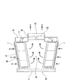
図1は、前記冷却塔を示す概略図である。
前記冷却塔は、図1に示すように、側面周面に外気取入口51が形成され上面中央部に外気排出口52が形成された略円柱状又は角柱状のケーシング50と、該ケーシング50内側で外気取入口51に沿うように配され原水Aと外気Bとを接触させて熱交換により原水Aを冷却する冷却部60と、該冷却部60に原水Aを散水供給するように冷却部60の上方に配された原水供給部70と、冷却部60により冷却された冷水を収容する冷水槽80と、該冷却部60にて包囲されるようにケーシング50内の中央部に形成された通風空間90を介して、冷却に用いられた外気Bを外気排出口52へ排出する送風機100とを備えている。
前記冷却部60は、ケーシング50内の中央側に通風空間90が形成されるようにケーシング50内の外側寄りに配されている。
また、前記冷却部60は、冷却塔用充填材1が複数段上下方向に連結された状態で充填されてなり、原水供給部70により上方から供給された原水Aとケーシング50の外気取入口51を介して側方から供給された外気Bとを、冷却塔用充填材1内にて熱交換させ、冷却された原水Aを冷水槽80に排出し、熱交換によって加熱された外気Bを中央部の通風空間90に排出するように構成されている。
FIG. 1 is a schematic view showing the cooling tower.
As shown in FIG. 1, the cooling tower includes a substantially columnar or
The
The
次に、上記の如き冷却塔に複数段充填された本実施形態の冷却塔用充填材1及び該冷却塔用充填材1を構成する充填材用シート5について説明する。
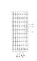
図2は、冷却塔用充填材1を外気Bが供給される側から見た状態を示す図であり、図3は、冷却塔用充填材1を構成する充填材用シート5を示す平面図である。
図2、図3に示すように、本実施形態の冷却塔用充填材1は、複数の突起部6及び凹入部7を有する充填材用シート5が複数枚積層されて構成され、冷却部60に充填された状態に於いて、層間に上方から原水Aが供給され且つ側方から外気Bが供給されることにより原水Aを外気Bと接触させて冷却するようになっている。
前記冷却塔用充填材1は、積層された充填材用シート5の複数の突起部6及び凹入部7によって、層間に空間が形成されてなり、該空間が形成されることにより原水Aや外気Bが層間に供給されうるようになっている。
Next, the
FIG. 2 is a diagram showing a state in which the cooling
As shown in FIGS. 2 and 3, the
The
即ち、前記冷却塔用充填材1は、図2に示すように、各充填材用シート5が積層された状態に於いて、一の充填材用シート5の突起部6の表側と、次に積層された充填材用シート5の凹入部7の裏側とが互いに対向し当接するように積層され、各突起部6の高さと凹入部7の深さとの和に応じた空間が層間に形成されている。
また、前記冷却用充填材1は、層間が略一定厚となるように、突起部6の高さ及び凹入部7の深さが一定に調整されており、各充填材用シート5が略平行をなすように積層されている。
尚、各充填材用シート5は、それぞれ接着剤を用いた接着等によって積層状態で維持されている。
前記冷却塔用充填材1に於ける各充填材用シート5間の間隔(充填材用シート5が平行に配置された状態において、一の充填材用シート5の後述する波模様8の稜線8aの頂点と隣接する他の充填材用シート5の波模様8の稜線8aの頂点との幅方向の間隔)は、通常10〜40mm程度である。また、冷却塔用充填材1を構成するのに必要な充填材用シート5の枚数としては、必要とされる充填材1の大きさにもよるが、通常、10〜30枚程度である。
That is, as shown in FIG. 2, the
Further, the cooling
In addition, each sheet |
Spacing between the
前記充填材用シート5は、図3に示すように、平板状で且つ正面視が長方形(正方形も含む)または平行四辺形(鋭角コーナーで通常、75度以上90度未満)に形成されてなり、前記突起部6及び凹入部7がその表面に形成されている。
前記充填材用シート5は、合成樹脂が用いられ、金型を用いたプレス成形などにより一体的に形成されてなり、その大きさは特に限定されるものではないが底面の長さ及び高さがそれぞれ400〜1000mm程度に設定され、また、その厚みは、通常、0.2〜0.7mm程度である。
As shown in FIG. 3, the
The
前記充填材用シート5に用いられる合成樹脂としては、例えば、硬質ポリ塩化ビニル、ポリプロピレン等を挙げることができる。
Examples of the synthetic resin used for the
前記突起部6は、それぞれ外方に突出するように形成されてなり、その大半は、外気Bの流れ方向に長い扁平状の円錐台形状に形成された扁平突起部6とされている。
図4は、該扁平突起部6を示し、(イ)は扁平突起部6を頂部側から見た面(即ち、正面)の概略図であり、(ロ)は(イ)のA−A線概略断面図であり、(ハ)は(イ)のB−B線概略断面図である。
図4及び図3に示すように、前記扁平突起部6は、断面形状が外気Bの流れ方向に扁平な楕円形状(詳しくは、長手方向両端部が円弧状で短手方向両端部が直線状の形状)に形成された柱状の土台部9上に形成されており、断面形状が楕円形で頂部6aに向けてテーパー状に断面積が縮小し且つ頂部6aが平面状とされた円錐台形に形成されてなる。
前記平面突起部6には、短手方向両端部に、突出方向に沿って延在する溝6bが、補強用リブとして形成されている。
前記扁平突起部6の長手方向長L1は、通常、10〜40mm、短手方向長L2は、通常、5〜20mmであり、好ましくは、扁平率(短手方向長L2/長手方向長L1)が0.25〜0.75に設定されている。
また、突起高さL3は、通常、5〜35mmに設定され、垂線に対する傾斜角αおよびβは、通常、5〜35度程度に設定されている。
更に、前記扁平突起部6の密度は、1m2当たり、通常100〜200個程度である。また、溝6bで形成される補強用リブの高さ(溝6bの深さ)は特に限定されないが、1〜3mmに設定されている。
尚、前記補強用リブは、空気を流通させる際の圧力損失を低減するという観点から、溝6bによって形成されることが好ましいが、単に扁平突起部6を補強するという観点からは溝6bによって形成されているものに限定されず、扁平突起部6の短手方向両端部の表面に突起筋として形成されていてもよい。
Each of the
FIG. 4 shows the
As shown in FIGS. 4 and 3, the
The length L1 in the longitudinal direction of the
In addition, the protrusion height L3 is normally set to 5 to 35 mm, and the inclination angles α and β with respect to the perpendicular are normally set to about 5 to 35 degrees.
Further, the density of the
The reinforcing rib is preferably formed by the
前記凹入部7は、それぞれ前記扁平突起部6の突出方向と反対方向に凹入するように形成されてなる。
図5は、凹入部7を示し、(イ)は、凹入部7の正面概略図であり、(ロ)は(イ)のA−A線概略断面図であり、(ハ)は(イ)のB−B線概略断面図である。
図5及び図3に示すように、前記凹入部7は、断面形状が円形等をなすように凹入しており、該凹入部7は裏面側に於いては同形状に突起した突起部をなしている。
前記凹入部7の大きさは、通常、直径L4が10〜45mm程度に設定されている。
また、凹入深さL5(後述する波模様8の谷部分からの深さ)は、2〜10mmに設定されている。
また、前記凹入部7の密度は、前記扁平突起部6と同じ値に設定されている。
The recessed
FIG. 5 shows the recessed
As shown in FIGS. 5 and 3, the recessed
The size of the recessed
Further, the indentation depth L5 (depth from the valley portion of the
The density of the recessed
前記扁平突起部6及び凹入部7は、図3に示すように、外気Bの流れ方向に沿って列をなすように且つ該列が上下方向に複数段形成されるように、好ましくは、高さ1m当たりに5〜20段形成されるように配されてなる。
尚、図3においては、15段形成されたものが示されている。
また、同じ列においては、扁平突起部6と凹入部7とが1つずつ交互に入れ替わるように配列されている。
更に、前記扁平突起部6の大半は、上段の扁平突起部6の鉛直真下から位置ズレして配されてなり、全体的に千鳥状に配置されている。また、前記凹入部7も同様に、その大半は、上段の凹入部7の鉛直真下から位置ズレして配されてなり、全体的に千鳥状に配置されている。
As shown in FIG. 3, the
In FIG. 3, 15 stages are shown.
Moreover, in the same row | line | column, it arrange | positions so that the
Furthermore, most of the
図6は、充填材用シート5が積層された状態に於ける扁平突起部6及び凹入部7を示す概略断面端面図である。
各充填材用シート5は、上記の如く、積層状態に於いて一の充填材用シート5の扁平突起部6と、次に積層された充填材用シート5の凹入部7とが互いに対向し当接するように積層されており、詳しくは、図6に示すように、各充填材用シート5においては、積層状態では、各扁平突起部6の頂部6a上面側と凹入部7の底部裏面側とが当接するように各扁平突起部6と凹入部7とが配置されて、それぞれ積層されている。
FIG. 6 is a schematic cross-sectional end view showing the
In each of the
前記充填材用シート5は、前記扁平突起部6及び凹入部7が形成された部分以外の略全域に、その表面積を増大させるべく、表面が波打った波模様8が形成されてなる(図3に於いては一部のみ示す。)。
尚、前記波模様8における山の部分は、前記扁平突起部6よりも低く設定されている。
また、前記波模様8は、その稜線8a(図3においては太線で示されている。)及び谷線8b(図3においては細線で示されている。)が互いに平行し且つ上方から下方に移動する際に、ジグザグに蛇行するように形成されている。尚、前記波模様8の高さ(前記稜線8aの頂点と谷線8bの頂点の間の高さ)は、特に限定されないが3〜10mm程度である。
The filling
The peak portion of the
Further, the
本実施形態の冷却塔用充填材1及び充填材用シート5は、上記の如く、充填材用シート5の表面に波模様8が形成されてなるので、該充填材用シート5の表面に沿って流れる原水Aの表面積を増大させることができ、効率よく外気Bと熱交換をさせることができる。
また、波模様8は、その稜線8a及び谷線8bが上方から下方に移動する際に、ジグザグに蛇行するように形成されてなるので、上方から下方に谷線8bに沿って流れる原水Aの滞留時間を長くすることができ、原水Aをより低い温度に冷却させることができる。
Since the
Further, the
本実施形態の冷却塔用充填材1及び充填材用シート5は、上記の如く構成されたが本発明においては、上記構成に限定されず適宜設計変更可能である。
例えば、本実施形態においては、凹入部7は断面円形等に形成されたが、具体的には、扁平突起部6と同様に、断面形状が外気Bの流れ方向に長い扁平な楕円形状に形成されていてもよい。
また、本実施形態の冷却塔用充填材1及び充填材用シート5は、扁平突起部6が柱状の土台部9上に形成されたが、本発明に於いては、土台部9が無い態様のものであってもよい。更に、本実施形態に於いては、扁平突起部6には補強リブが形成されたが、本発明に於いては、強度に問題が無い場合等には補強リブが形成されていない態様のものであってもよい。
The
For example, in the present embodiment, the recessed
Further, in the
A・・・原水、B・・・外気、5・・・充填材用シート、6・・・扁平突起部、
6b・・・補強リブ
A ... Raw water, B ... Outside air, 5 ... Filler sheet, 6 ... Flat projection,
6b ... Reinforcing rib
Claims (3)
前記突起部の少なくとも一部が、外気の流れ方向に長い扁平状の円錐台形状に形成された扁平突起部とされてなり、
前記充填材用シートには、前記扁平突起部の突出方向と反対方向に凹入する凹入部が形成されており、
該凹入部が、裏面側に於いて突出した突起部をなしており、
前記扁平突起部は、対向する充填材用シートの前記凹入部の裏側の突起部に当接される部分であり、
前記充填材用シートには、前記扁平突起部及び前記凹入部以外の部分に、表面が波打った波模様が形成されており、
前記扁平突起部は、外気の流れ方向に沿って列をなすように且つ該列が上下方向に複数段形成されるように配されてなり、
前記扁平突起部の少なくとも一部は、上段の扁平突起の鉛直真下から位置ズレして配されていることを特徴とする冷却塔用充填材。 A plurality of filler sheets having a plurality of protrusions are stacked and arranged in a cooling tower, and raw water is supplied from above by supplying raw water from above and outside air from the side. A cooling tower filler that cools in contact with outside air,
At least a part of the protrusion is a flat protrusion formed in a flat truncated cone shape that is long in the flow direction of outside air,
The filler sheet has a recessed portion that is recessed in a direction opposite to the protruding direction of the flat protrusion,
The recessed portion forms a protruding portion protruding on the back side,
The flat protrusion is a part that comes into contact with the protrusion on the back side of the recessed portion of the opposing filler sheet,
In the sheet for filler, a wave pattern having a waved surface is formed in a portion other than the flat protrusion and the recessed portion ,
The flat protrusions are arranged so as to form a row along the flow direction of the outside air, and the row is formed in a plurality of stages in the vertical direction,
At least a part of the flat protrusion is arranged so as to be displaced from a position directly below the upper flat protrusion.
前記突起部の少なくとも一部が、一方向に長い扁平状の円錐台形状に形成された扁平突起部とされてなることを特徴とする充填材用シート。 A sheet for a filler having a plurality of protrusions constituting the cooling tower filler according to claim 1 or 2 by lamination,
At least a part of the projecting portion is a flat projecting portion formed in a flat truncated cone shape that is long in one direction.
Priority Applications (3)
| Application Number | Priority Date | Filing Date | Title |
|---|---|---|---|
| JP2009107777A JP5373468B2 (en) | 2009-04-27 | 2009-04-27 | Cooling tower filler and filler sheet |
| PCT/JP2010/057480 WO2010126050A1 (en) | 2009-04-27 | 2010-04-27 | Filler material and filler sheet for cooling towers |
| CN2010800101040A CN102341668A (en) | 2009-04-27 | 2010-04-27 | Filler material and filler sheet for cooling towers |
Applications Claiming Priority (1)
| Application Number | Priority Date | Filing Date | Title |
|---|---|---|---|
| JP2009107777A JP5373468B2 (en) | 2009-04-27 | 2009-04-27 | Cooling tower filler and filler sheet |
Publications (2)
| Publication Number | Publication Date |
|---|---|
| JP2010255953A JP2010255953A (en) | 2010-11-11 |
| JP5373468B2 true JP5373468B2 (en) | 2013-12-18 |
Family
ID=43317072
Family Applications (1)
| Application Number | Title | Priority Date | Filing Date |
|---|---|---|---|
| JP2009107777A Active JP5373468B2 (en) | 2009-04-27 | 2009-04-27 | Cooling tower filler and filler sheet |
Country Status (1)
| Country | Link |
|---|---|
| JP (1) | JP5373468B2 (en) |
Cited By (1)
| Publication number | Priority date | Publication date | Assignee | Title |
|---|---|---|---|---|
| KR101839428B1 (en) | 2017-07-03 | 2018-03-16 | 이헌수 | Filler of spiral type for cooling tower |
Families Citing this family (2)
| Publication number | Priority date | Publication date | Assignee | Title |
|---|---|---|---|---|
| KR101723160B1 (en) * | 2015-04-24 | 2017-04-05 | 스피어다인 주식회사 | Filling sheet for cooling tower and filling sheet stack for cooling tower by using the same |
| CN111928719B (en) * | 2019-07-15 | 2022-07-08 | 德州贝诺风力机械设备有限公司 | Packing module and cooling tower |
Family Cites Families (7)
| Publication number | Priority date | Publication date | Assignee | Title |
|---|---|---|---|---|
| JPS544527Y2 (en) * | 1977-02-02 | 1979-02-27 | ||
| JPS6066997U (en) * | 1983-10-12 | 1985-05-13 | 芙蓉エンジニアリング株式会社 | Heat exchange filler |
| JPH021239U (en) * | 1988-06-10 | 1990-01-08 | ||
| GB2258524B (en) * | 1991-08-08 | 1995-05-31 | Nat Power Plc | Film type packing element for use in cooling towers |
| JP3898366B2 (en) * | 1998-12-25 | 2007-03-28 | 三菱樹脂株式会社 | White smoke prevention type cooling tower filler and white smoke prevention type cooling tower |
| JP2001255099A (en) * | 2000-03-09 | 2001-09-21 | Izumi Kasei Kogyo Kk | Contact media of cooling tower |
| JP4157964B2 (en) * | 2003-03-13 | 2008-10-01 | 株式会社荏原シンワ | Filler unit used in closed crossflow heat exchange towers |
-
2009
- 2009-04-27 JP JP2009107777A patent/JP5373468B2/en active Active
Cited By (1)
| Publication number | Priority date | Publication date | Assignee | Title |
|---|---|---|---|---|
| KR101839428B1 (en) | 2017-07-03 | 2018-03-16 | 이헌수 | Filler of spiral type for cooling tower |
Also Published As
| Publication number | Publication date |
|---|---|
| JP2010255953A (en) | 2010-11-11 |
Similar Documents
| Publication | Publication Date | Title |
|---|---|---|
| JP4907703B2 (en) | Microchannel heat exchanger, method of cooling the heat source | |
| CN107110627B (en) | Cooling tower using bidirectional packing | |
| US10386135B2 (en) | Cooling tower integrated inlet louver fill | |
| KR100359536B1 (en) | Film fill-pack for inducement of spiraling gas flow in heat and mass transfer contact apparatus with self-spacing fill-sheets | |
| JP5373468B2 (en) | Cooling tower filler and filler sheet | |
| KR101569366B1 (en) | Fill for cross flow type of cooling tower | |
| US20040031599A1 (en) | Heat exchanger | |
| JP5888166B2 (en) | Battery module and vehicle | |
| JP4848718B2 (en) | Heat exchanger | |
| WO2010126050A1 (en) | Filler material and filler sheet for cooling towers | |
| JP2003302176A (en) | Boiling cooler | |
| JP5581103B2 (en) | Cooling tower filler and filler sheet | |
| KR100338718B1 (en) | Film fill-pack for inducement of spiraling gas flow in heat and mass transfer contact apparatus with self-spacing fill-sheets | |
| CA2919962C (en) | Cooling tower fill | |
| KR101730890B1 (en) | Plastic Heat Exchanger for Heat Recovery | |
| KR102571858B1 (en) | Separation type evaporative cooler | |
| KR20050072697A (en) | Air cooling device and air cooling method | |
| KR101384359B1 (en) | Filler for cooling tower | |
| KR20100059140A (en) | Heat exchange element for ventilating duct | |
| JP6422585B2 (en) | Plate heat exchanger | |
| JP7168512B2 (en) | Packing plate for gas-liquid contact, cross-flow cooling tower | |
| JP5206032B2 (en) | Heat exchanger | |
| JP5675201B2 (en) | Heat medium diffusing member and air conditioning system | |
| CN218805095U (en) | Do benefit to warm braw core that reduces air-out difference in temperature | |
| JP2005156037A (en) | Crossflow type cooling tower |
Legal Events
| Date | Code | Title | Description |
|---|---|---|---|
| A131 | Notification of reasons for refusal |
Free format text: JAPANESE INTERMEDIATE CODE: A131 Effective date: 20111118 |
|
| A02 | Decision of refusal |
Free format text: JAPANESE INTERMEDIATE CODE: A02 Effective date: 20120720 |
|
| A521 | Request for written amendment filed |
Free format text: JAPANESE INTERMEDIATE CODE: A523 Effective date: 20121022 |
|
| A911 | Transfer to examiner for re-examination before appeal (zenchi) |
Free format text: JAPANESE INTERMEDIATE CODE: A911 Effective date: 20121029 |
|
| A912 | Re-examination (zenchi) completed and case transferred to appeal board |
Free format text: JAPANESE INTERMEDIATE CODE: A912 Effective date: 20121228 |
|
| A521 | Request for written amendment filed |
Free format text: JAPANESE INTERMEDIATE CODE: A523 Effective date: 20130802 |
|
| RD04 | Notification of resignation of power of attorney |
Free format text: JAPANESE INTERMEDIATE CODE: A7424 Effective date: 20130805 |
|
| A61 | First payment of annual fees (during grant procedure) |
Free format text: JAPANESE INTERMEDIATE CODE: A61 Effective date: 20130919 |
|
| R150 | Certificate of patent or registration of utility model |
Ref document number: 5373468 Country of ref document: JP Free format text: JAPANESE INTERMEDIATE CODE: R150 Free format text: JAPANESE INTERMEDIATE CODE: R150 |
|
| R250 | Receipt of annual fees |
Free format text: JAPANESE INTERMEDIATE CODE: R250 |
|
| R250 | Receipt of annual fees |
Free format text: JAPANESE INTERMEDIATE CODE: R250 |
|
| R250 | Receipt of annual fees |
Free format text: JAPANESE INTERMEDIATE CODE: R250 |
|
| R250 | Receipt of annual fees |
Free format text: JAPANESE INTERMEDIATE CODE: R250 |
|
| R250 | Receipt of annual fees |
Free format text: JAPANESE INTERMEDIATE CODE: R250 |
|
| R250 | Receipt of annual fees |
Free format text: JAPANESE INTERMEDIATE CODE: R250 |
|
| R250 | Receipt of annual fees |
Free format text: JAPANESE INTERMEDIATE CODE: R250 |
|
| R250 | Receipt of annual fees |
Free format text: JAPANESE INTERMEDIATE CODE: R250 |