JP5367709B2 - Fluid-filled seal that contacts the human body - Google Patents
Fluid-filled seal that contacts the human body Download PDFInfo
- Publication number
- JP5367709B2 JP5367709B2 JP2010523085A JP2010523085A JP5367709B2 JP 5367709 B2 JP5367709 B2 JP 5367709B2 JP 2010523085 A JP2010523085 A JP 2010523085A JP 2010523085 A JP2010523085 A JP 2010523085A JP 5367709 B2 JP5367709 B2 JP 5367709B2
- Authority
- JP
- Japan
- Prior art keywords
- fluid
- chamber
- ostomy appliance
- appliance according
- fluid flow
- Prior art date
- Legal status (The legal status is an assumption and is not a legal conclusion. Google has not performed a legal analysis and makes no representation as to the accuracy of the status listed.)
- Expired - Fee Related
Links
Images


Classifications
-
- A—HUMAN NECESSITIES
- A61—MEDICAL OR VETERINARY SCIENCE; HYGIENE
- A61F—FILTERS IMPLANTABLE INTO BLOOD VESSELS; PROSTHESES; DEVICES PROVIDING PATENCY TO, OR PREVENTING COLLAPSING OF, TUBULAR STRUCTURES OF THE BODY, e.g. STENTS; ORTHOPAEDIC, NURSING OR CONTRACEPTIVE DEVICES; FOMENTATION; TREATMENT OR PROTECTION OF EYES OR EARS; BANDAGES, DRESSINGS OR ABSORBENT PADS; FIRST-AID KITS
- A61F5/00—Orthopaedic methods or devices for non-surgical treatment of bones or joints; Nursing devices; Anti-rape devices
- A61F5/44—Devices worn by the patient for reception of urine, faeces, catamenial or other discharge; Portable urination aids; Colostomy devices
- A61F5/445—Colostomy, ileostomy or urethrostomy devices
-
- A—HUMAN NECESSITIES
- A61—MEDICAL OR VETERINARY SCIENCE; HYGIENE
- A61F—FILTERS IMPLANTABLE INTO BLOOD VESSELS; PROSTHESES; DEVICES PROVIDING PATENCY TO, OR PREVENTING COLLAPSING OF, TUBULAR STRUCTURES OF THE BODY, e.g. STENTS; ORTHOPAEDIC, NURSING OR CONTRACEPTIVE DEVICES; FOMENTATION; TREATMENT OR PROTECTION OF EYES OR EARS; BANDAGES, DRESSINGS OR ABSORBENT PADS; FIRST-AID KITS
- A61F5/00—Orthopaedic methods or devices for non-surgical treatment of bones or joints; Nursing devices; Anti-rape devices
- A61F5/44—Devices worn by the patient for reception of urine, faeces, catamenial or other discharge; Portable urination aids; Colostomy devices
- A61F5/4404—Details or parts
- A61F5/4407—Closure means other than valves
Abstract
Description
(本発明の分野)
本発明は、オストミー装具、さらに具体的には、人の身体に接触し、身体オリフィスの位置、近傍、または周囲においてシールを形成するための流体充填シールを有する排泄制御オストミー装具に関する。シールはオストミー装具での使用に特に適し、また大便の失禁デバイスおよびカテーテルに利用され得る。
(Field of the Invention)
The present invention relates to ostomy appliances, and more particularly to an excretion control ostomy appliance having a fluid-filled seal for contacting a human body and forming a seal at, near, or around the body orifice. The seal is particularly suitable for use with ostomy appliances and can be utilized for stool incontinence devices and catheters.
(本発明の背景)
特許文献1、特許文献2は、膨張可能な膜シールを含み、流体充填膨張チャンバーを少なくとも部分的に取り囲む膜から成る、制御されたオストミー排泄デバイスを説明する。膜シールは、ストーマの一時的な共形の閉鎖を生成するように意図されている。デバイスがストーマの上に配置され、膨張チャンバーが膨張させられるとき、膜シールはチャンバー内の膨張流体の圧力に依存する接触力分布で、ストーマに合致しこれを支える。膜シールはストーマからの大便放出を阻止し、同時に、腸内ガス流出の圧力下でストーマ組織から局部的に小さな距離を隔てることにより腸内ガスの放出を可能にするように意図される。
(Background of the present invention)
U.S. Patent Nos. 6,099,056 and 6,037,037 describe controlled ostomy excretion devices that comprise an inflatable membrane seal and consist of a membrane that at least partially surrounds a fluid-filled inflation chamber. The membrane seal is intended to create a temporary conformal closure of the stoma. When the device is placed over the stoma and the expansion chamber is inflated, the membrane seal conforms to and supports the stoma with a contact force distribution that depends on the pressure of the inflation fluid in the chamber. The membrane seal is intended to prevent stool release from the stoma, while at the same time allowing intestinal gas release by locally separating a small distance from the stoma tissue under the pressure of intestinal gas outflow.
従来技術のシールの膨張可能な容積は、ポンプまたはシリンジから空気または生理食塩水のような膨張流体の注入を可能にするチェックバルブによって閉じられる。チェックバルブはチャンバーからの膨張流体の排出を、排出の結果、回復不能な膨張圧力損失および当然の帰結としてストーマに対する接触圧力の損失を招き、大便がシールを通過する偶発的漏出リスクにつながるので、防止する。 The inflatable volume of the prior art seal is closed by a check valve that allows the infusion of inflation fluids such as air or saline from a pump or syringe. The check valve drains inflation fluid from the chamber, resulting in unrecoverable inflation pressure loss and, as a consequence, loss of contact pressure to the stoma, leading to the risk of accidental leakage of stool passing through the seal, To prevent.
特許文献2の1つの実施形態は、流体充填チャンバーの背後および外側に配置される弾力性の発泡体支持を含む。発泡体支持は、流体充填チャンバーの膨張特性を変化させることなく、膨張可能な容積の背後でバネ作用を提供する。バネ作用は、閉じた膨張容積からの膨張流体の偶発的部分的な損失を部分的に補償し得、ストーマとデバイスの蓋との間の距離の変化を部分的に収容する。 One embodiment of U.S. Patent No. 6,053,836 includes a resilient foam support disposed behind and outside the fluid filled chamber. The foam support provides a spring action behind the expandable volume without changing the expansion characteristics of the fluid filled chamber. The spring action may partially compensate for the accidental partial loss of inflation fluid from the closed inflation volume and partially accommodates the change in distance between the stoma and the device lid.
本発明の考案において、発明者は対処が望まれる新規の課題を理解してきた。膜シールがストーマと接触しているときに、ストーマと膜シールとの間の接触圧力は、大便の排出に対抗する効果的一時的なシールは維持する一方で、狭い範囲に、すなわち、(ストーマ組織に良好な血液灌流を確保するように)できるだけ低く維持されることが重要である。しかしながら、チャンバー内の所定の量の膨張流体に対して、ストーマの移動で引き起こされるチャンバー容積の任意の変化は直接的に膨張圧力に影響するので、そのような狭い範囲に接触圧力を維持することは困難である。 Inventing the present invention, the inventor has understood a new problem to be addressed. When the membrane seal is in contact with the stoma, the contact pressure between the stoma and the membrane seal remains within a narrow range, i.e. (stoma), while maintaining an effective temporary seal against stool discharge. It is important to keep it as low as possible (to ensure good blood perfusion in the tissue). However, for a given amount of inflation fluid in the chamber, any change in the chamber volume caused by the movement of the stoma directly affects the inflation pressure, so maintain the contact pressure in such a narrow range. It is difficult.
発明者は、オストミー装具の着用時間中、ストーマが身体に向かって内側におよび/またはストーマ周囲の皮膚から1cmを越え得る総距離を越えて外側に離れる方向に活発に動き得ることをさらに理解してきた。この動きは腸の蠕動運動、ストーマからの大便またはガスの差し迫った放出、または腹部の筋肉の収縮に基づいている。ストーマが身体に向かって内側に移動する(すなわち、膨張チャンバーの容積が増加する)ときの状態下では、膜シールとストーマとの間の接触圧力は降下し得、接触圧力があまりに低くなる場合には大便の漏出リスクが増加する。対照的に、ストーマまたはその内容物が外側に向かって膜シールを押す(膨張チャンバーの容積が減少する)ときの状態下では、シールとストーマとの間の接触圧力は潜在的に上昇し得る。そのような時間中は、増加させられた接触圧力が結果としてストーマにおける望ましくない血液灌流の低下を招く。そのような状態の期間は非常に予測不能であり得、一部はただの数秒、他は数分、また時には数時間続く。 The inventor has further understood that during the time of wearing the ostomy brace, the stoma can actively move inwardly towards the body and / or outward beyond a total distance that can exceed 1 cm from the skin surrounding the stoma. It was. This movement is based on peristaltic movement of the intestines, imminent release of stool or gas from the stoma, or contraction of the abdominal muscles. Under conditions when the stoma moves inward toward the body (ie, the volume of the expansion chamber increases), the contact pressure between the membrane seal and the stoma can drop and if the contact pressure becomes too low Increases the risk of stool leakage. In contrast, under conditions when the stoma or its contents push the membrane seal outward (decreasing the volume of the expansion chamber), the contact pressure between the seal and the stoma can potentially increase. During such time, the increased contact pressure results in undesirable blood perfusion reduction in the stoma. The duration of such a state can be very unpredictable, some lasting just a few seconds, others lasting minutes and sometimes hours.
本発明は上述の課題を理解して考案された。 The present invention has been devised by understanding the above-mentioned problems.
(本発明の概要)
本発明の第1の局面は、流体充填シールを有する排泄制御オストミー装具を提供し、シールは、(第1の)流体チャンバーの移動可能な壁を形成する流体不浸透性膜、流体チャンバーと連絡する1つ以上のポート、および流体チャンバー内に配置される弾力性デバイスを備える。弾力性デバイスは、(i)使用中にシールを形成する、および/または(ii)チャンバーを拡張する方向に膜を動かすように構成される。
(Outline of the present invention)
A first aspect of the present invention provides an excretion control ostomy appliance having a fluid filled seal, the seal being in communication with the fluid chamber, a fluid impermeable membrane forming a movable wall of the (first) fluid chamber. One or more ports, and a resilient device disposed within the fluid chamber. The resilient device is configured to move the membrane in a direction that (i) forms a seal during use and / or (ii) expands the chamber.
そのような構成で、チャンバーの膨張度合いは、チャンバー内の流体容積と、同じくチャンバー内の弾力性デバイスとの両方の関数である。これは、ストーマ突起の度合いにおける変化を収容するように、チャンバー容積がダイナミックに管理されるのを可能にする。ストーマが内側に移動すると、弾力性デバイスはストーマの移動を補償するようにチャンバーを拡張するために力を加え得る。これは上述した従来技術の発泡体配列と対照的であり、従来技術においては膨張チャンバーの背後の発泡体バネが常時背後からチャンバーを圧縮する傾向があり、ストーマ移動に対して補償するようにチャンバーを拡張することは決してあり得ない。 With such a configuration, the degree of expansion of the chamber is a function of both the fluid volume within the chamber and the resilient device also within the chamber. This allows the chamber volume to be managed dynamically to accommodate changes in the degree of stoma protrusion. As the stoma moves inward, the resilient device may apply force to expand the chamber to compensate for stoma movement. This is in contrast to the prior art foam arrangement described above, where the foam spring behind the expansion chamber always tends to compress the chamber from behind, so that the chamber is compensated for stoma movement. Can never be extended.
膜によって加えられるシール圧力は、弾力性デバイスによって加えられる弾性力およびチャンバー内の流体圧力の関数である。ポートはチャンバーに対する流体の流入および/または排出を制御するように構成される。ポートの特性は、いかにシールを膨張圧力の増加または減少に応答して適用するかを決める。例えば、膨張圧力が一定の閾値以下に降下する場合(ストーマが内側に移動してチャンバー容積が増加する場合)、ポートは膨張圧力を回復させるために追加の膨張流体の流入を可能にするように構成される。膨張圧力が上昇すると(ストーマが外側に移動してチャンバー容積が減少する場合)、ポートはチャンバーからの流体放出を遮断または少なくとも遅らせるように構成され得る。これはシールがストーマからの短期間の要求に耐えることを可能にするが、流体は時間を延長して流出されるので延長された時間中、高い接触圧力を維持する必要はない。ポートは、弾力性デバイスの収縮/拡張に対して制動作用を制御し得る。制動作用は、収縮方向においては拡張方向とは異なり得る。 The sealing pressure applied by the membrane is a function of the elastic force applied by the elastic device and the fluid pressure in the chamber. The port is configured to control fluid inflow and / or evacuation to the chamber. The characteristics of the port determine how the seal is applied in response to an increase or decrease in inflation pressure. For example, if the inflation pressure drops below a certain threshold (when the stoma moves inward and the chamber volume increases), the port will allow the inflow of additional inflation fluid to restore the inflation pressure Composed. As the inflation pressure increases (when the stoma moves outwards and the chamber volume decreases), the port can be configured to block or at least delay fluid discharge from the chamber. This allows the seal to withstand short-term demands from the stoma, but the fluid is drained for an extended period of time so there is no need to maintain a high contact pressure for an extended period of time. The port may control the braking action against contraction / expansion of the elastic device. The braking action may differ from the expansion direction in the contraction direction.
本発明の他の局面は、1つ以上の特徴またはさらに以下で議論される特徴の任意の組み合わせで要約される。 Other aspects of the invention are summarized in one or more features or any combination of features discussed further below.
本発明は排泄制御オストミー装具であり、装具は膜シールを含み、膜シールは弾力性発泡体を含む。受け入れられる発泡体は連続発泡体または不連続発泡体を含む。発泡体の形状は、円形の断面を有する円筒形、楕円形の断面を有するブロック、または多角形の断面を有するブロックであり得る。ストーマに向かうまたはストーマから離れる方向に面する発泡体の表面は、円錐プロファイルまたは後方に傾いた(swept)円弧によって形成されるプロファイルを有する凹形、円錐プロファイルまたは後方に傾いた(swept)円弧によって形成されるプロファイルを有する凸形から選択される形状を含む。 The present invention is an excretion controlled ostomy appliance, the appliance including a membrane seal, the membrane seal including a resilient foam. Accepted foams include continuous foams or discontinuous foams. The shape of the foam can be a cylinder with a circular cross section, a block with an elliptical cross section, or a block with a polygonal cross section. The surface of the foam facing towards the stoma or away from the stoma is formed by a concave, conical profile or swept arc with a profile formed by a conical profile or a swept arc. Including a shape selected from convex shapes having a profile to be formed.
ストーマに面する発泡体表面は滑らかな「皮膚状の」表面であり得る。発泡体の1つ以上の表面は、例えば、多角形、一続きの放射状の線、1つ以上の円周状リングといった幾何学的模様の隆起または溝のようなランダムな織地を有し得る。模様は繰り返しであり得る。 The foam surface facing the stoma can be a smooth “skin-like” surface. One or more surfaces of the foam may have a random texture such as, for example, a geometric pattern of ridges or grooves, such as polygons, a series of radial lines, one or more circumferential rings. The pattern can be repeating.
膜シールは、シールに加えられる力に応答して膜シールに流体が出入りすることを可能にするために、望ましくは1つ以上の開口を包含する。1つ以上の開口は流体流動制限部材を包含する。制限部材は小さな穴、微孔性膜の部分、穴の開いたフィルムの部分、または多孔性のプラグによって提供され得る。 The membrane seal desirably includes one or more openings to allow fluid to enter and exit the membrane seal in response to a force applied to the seal. The one or more openings include a fluid flow restriction member. The restricting member may be provided by a small hole, a microporous membrane part, a perforated film part, or a porous plug.
また、膜シールは好ましくは所定の圧力が越えられると開く吸入チェックバルブおよび放出バルブを包含する。放出バルブは一旦開けられると恒久的に開き続ける。流体は一旦所定の圧力が越えられると破裂または破壊されるシールを通って放出される。 The membrane seal also preferably includes an intake check valve and a discharge valve that open when a predetermined pressure is exceeded. Once opened, the discharge valve continues to open permanently. The fluid is released through a seal that is ruptured or broken once a predetermined pressure is exceeded.
本発明は膜シールを含む排泄制御オストミー装具としても説明され得、流体は閉じられ得る第1のバルブを通って膜シールに流入し、第2の開口を通って膜シールから放出される。 The present invention can also be described as an excretory controlled ostomy appliance including a membrane seal, where fluid flows into the membrane seal through a first valve that can be closed and is released from the membrane seal through a second opening.
第2の開口は所定の圧力が越えられると開くバルブである。バルブは一旦開けられると恒久的に開き続ける。流体は、一旦所定の圧力が越えられると破裂または破壊されるシールを通って放出される。 The second opening is a valve that opens when a predetermined pressure is exceeded. Once opened, the valve continues to open permanently. The fluid is released through a seal that is ruptured or broken once a predetermined pressure is exceeded.
第2の開口は(例えば、開いているときの第1の開口と比較して)流体流動制限部材を包含し得る。制限部材は小さな穴、微孔性膜の部分、穴の開いたフィルムの部分、または多孔性のプラグである。 The second opening may include a fluid flow restriction member (eg, as compared to the first opening when open). The limiting member is a small hole, a microporous membrane part, a perforated film part, or a porous plug.
膜シールは弾力性発泡体を含む。第1のバルブは吸入チェックバルブである。第1のバルブは流体流動制限部材を包含する。膜シールは第2の容積に接続される。膜シールから第2の容積までの流路は制限される。第2の容積から膜シールまでの流路は制限される。膜シールから第2の容積までの流路は所定の圧力が越えられると開く。 The membrane seal includes a resilient foam. The first valve is an intake check valve. The first valve includes a fluid flow restriction member. The membrane seal is connected to the second volume. The flow path from the membrane seal to the second volume is limited. The flow path from the second volume to the membrane seal is limited. The flow path from the membrane seal to the second volume opens when a predetermined pressure is exceeded.
いくつかの特徴が上記および添付の特許請求範囲の中で確認されてきた一方で、本明細書に説明されるおよび/または本発明の図に示される任意の特許性特徴に対しての保護が、主眼点がその上に置かれるか否かにかかわらず、要求され得る。 While several features have been identified above and in the appended claims, protection against any patentable feature described herein and / or shown in the figures of the present invention is , May be required regardless of whether the focus point is placed on it.
(好ましい実施形態の詳細な説明)
本発明の好ましい実施形態が、添付図を参照してここで説明される。同一の参照数字は同一のまたは類似の特徴を示すために適切な箇所で用いられる。
Detailed Description of Preferred Embodiments
Preferred embodiments of the present invention will now be described with reference to the accompanying drawings. The same reference numerals are used where appropriate to indicate the same or similar features.
図1を参照して、制御された排泄または排出のオストミー装具デバイスが、身体組織に対するシールを形成するために、身体の開口またはオリフィスの位置、近傍、または周囲において人の身体に接触する流体充填シールを採用して示される。本発明の実施形態である医用デバイスは、ストーマ12のためのオストミー装具10であるが、本発明は失禁管理デバイスおよびカテーテルに適用可能である。
Referring to FIG. 1, fluid filling where a controlled excretion or drainage ostomy appliance device contacts a human body at, near, or around a body opening or orifice to form a seal against body tissue. Shown with a seal. The medical device that is an embodiment of the present invention is an
オストミー装具10は、ストーマ周囲の皮膚16への粘着剤による取り付けのための開口付き粘着性身体装備14、開口付き粘着性身体装備14によって支持されるハウジング18、およびストーマ12に対してシールを形成するためにハウジング18の中または上に装着される流体充填シール20を概して備える。開口付き粘着性身体装備14は、粘着性物質を含む親水コロイドのような皮膚に優しい医療品質等級の粘着性物質を含む。ハウジング18は、開口付き粘着性身体装備14と一体であり得、またはカップリング22によって開口付き粘着性身体装備に取り外し可能に結合され得る。本発明の実施形態において、カップリング22は、相互に係合可能な機械的な結合リング22aおよび22bを備える。また、本発明の実施形態において、オプションの身体排泄物採集器24がハウジング18内に提供される。身体排泄物採集器24は柔軟なプラスチックフィルムから構成される。身体排泄物採集器24は、また、管状であり得、または1枚以上のフィルムシートから製作され得る。図1において、身体排泄物採集器24は収縮させられた状態で示され、カップリング22とハウジング18との間に装着される。身体排泄物採集器24は、ハウジング18とカップリングリング22bとの間の第2の取り外し可能な結合連結部(26に概略的に示される)によって初期のコンパクトな状態に維持される。
The
流体充填シール20は、支持壁30であってその中に画定される少なくとも1つのポート32を有する支持壁、および支持壁30から垂れ下がる柔軟な膜34を概して備える。柔軟な膜34および支持壁30は、ともにチャンバー36を画定し実質的に取り囲む。チャンバー36はポート32を除いて実質的に閉じている。柔軟な膜34は概して柔軟なプラスチックフィルムから構成され、膨張流体に対して不浸透性である。本発明の実施形態において、流体は空気であるが、後述するように他の気体または液体が所望に応じて用いられ得る。柔軟な膜34はチャンバー36の移動可能な壁として作用する。本発明の実施形態において、柔軟な膜34はストーマ12の組織に接触するシール表面を提供する。支持壁30は、柔軟な膜34より概して堅いプラスチックから構成され、自立する形状を提供する。柔軟な膜34は、例えば、溶接または接着剤によって支持壁30にシールされる。
The fluid filled
代替的な実施形態において、図1aを参照して、柔軟な膜34は別の部品55から垂れ下がり得、次に支持壁30から垂れ下げられる。別の部品は、例えば、バルブ、ポート、または他の機能的な特徴を組み込んだプラスチックフィルムであり得る。
In an alternative embodiment, referring to FIG. 1 a, the
弾力性デバイス38は、柔軟な膜34を拡張された形状にさせ、支持壁30から隔て、および/または柔軟な膜34をストーマ12に対してシールする位置に向かわせるようにチャンバー36内に提供される。本発明の実施形態において、弾力性デバイス38は弾力性の発泡体を備える。弾力性デバイス38はチャンバー36に概してぴったり合う寸法に作られ、それにより柔軟な膜34を拡張された形状に弾力を持って保持する。例えば、発泡体38は、発泡体38が恒久的に少なくとも部分的な圧縮状態にあるようにチャンバー36のサイズよりも大きな元々の形状を有し得る。発泡体38の形状はチャンバー36を実質的に充填するために選択され得、または発泡体38は1つ以上の空隙または間隙をチャンバー36に残し得る。発泡体38は、柔軟な膜34の支持壁30への取り付けに先立ってチャンバー36内に挿入され得、または柔軟な膜34の支持壁30への取り付け後にポート32を通してチャンバー36内に注入され得る。支持壁30は発泡体38が及ぼす反力を支える。本発明の実施形態において、発泡体38は、他の実施形態は円形というよりはむしろ楕円形または多角形の断面を組み込み得るが、概して円筒形または円板形状である。
A
脱臭フィルター50は、支持壁30の柔軟な膜34および弾力性デバイス38とは反対側に設置され、ストーマ12から発散する腸内ガスを脱臭する。フィルター50の吸入口50aは、身体排泄物採集器24の中にあり流体充填シール20を包囲している環状の空間52と連絡する。フィルター50の排出口50bは、ハウジング18内の1つ以上の放出開口54を経由して外気と連絡する。
The
使用に際して、柔軟な膜34によってストーマ12に加えられる接触圧力は、弾力性発泡体38の圧縮によって生成される力およびチャンバー36内の流体圧力の組み合わせである。発泡体38の特性は、所望の圧力に応じて選択され得る。本発明の実施形態において、ストーマ12に対して低接触圧力だけを提供することが望まれる場合には、発泡体38は概して柔らかい。例えば、発泡体38は、25%たわみにおける約30ポンド/50平方インチの力の押込み荷重値(Indention Force Dflection)を有する。しかしながら、この値の適切な範囲は10ポンド/50平方インチから45ポンド/50平方インチであり得る。しかしながら、発泡体38の特性は所望に応じて変化させられ得る。本発明の実施形態において、発泡体38は連続発泡体であるが、所望に応じて不連続発泡体またはスキンフォームが代わりに用いられ得る。上記で参照した押込み荷重値の測定は、試験方法に基づいた特有の単位を有する。その理由は試験が50平方インチの面積を有する圧力台座で実施されるからである。
In use, the contact pressure applied to stoma 12 by
発泡体38の柔軟な膜34近傍の端面38aは、概して平面であり得、または非平面の構成を有し得る。非平面の構成は、(i)流体充填シール20の局部的な圧力応答を修正し得、および/または(ii)流体充填シール20のシール特性を修正し得、および/または(iii)流体充填シール20のストーマ12の形状に合致させる能力を修正し得る。
The
例えば、発泡体38の端面38aは、ストーマ12の通常突き出た形状に合致するために凹形であり得る。凹形表面は、円錐プロファイルまたは後方に傾いた(swept)円弧によって形成されるプロファイルを有し得る。別の形態において、発泡体の端面38aは、発泡体38のシール特性を高めるためにランダムな、擬似ランダムな、または規則的な織地を有し得る。織地は、流体充填シール20の大便の放出を防止する能力を弱めることなく、柔軟な膜34の、ストーマ12とのインターフェイスとは反対側表面上の対応経路に沿っての腸内ガスの発散を容易にするために、局部的な圧力集中を軽減する領域、溝、または経路を提供し得る。図3に示されるさらなる形態において、非平面プロファイルは、島またはパッド領域40の間に1つ以上の隆起または溝42を含む。パッド領域40は1つ以上繰り返す多角形、放射状の配列、同心円の円周状リングまたは領域のように形作られ得る。溝42はいくつかの経路に沿って軽減された圧力集中を提供し、上述のように発泡体38ブロックのより快適な合致を容易にする。非平面プロファイルは、概して、ストーマ12に接触する中央領域44と、ストーマ周囲のシールのための周囲領域46に分割され得る。図示された非平面構成は、単に例示であり、端面38aの他の平面または非平面構成が将来の出願に望まれるものとして用いられ得る。
For example, the
チャンバー36内の流体(空気)圧力はポート32によって調整される。第1の実施形態において、ポート32は恒久的に開いており、チャンバー36の外気との呼吸を可能にする。接触圧力は発泡体38によって加えられる圧力に概して等しく、チャンバー36内の流体圧力はチャンバー36の外側の大気圧に概して等しく、流体は追加の接触圧力を何も生成しない。ストーマ12が内側にまたは外側に移動しても、流体(空気)は、チャンバー容積の変化を補償するようにして実質的に無制限に、ポート32を通ってチャンバー36に自由に入りおよび/またはチャンバーから出る。これは、ストーマ12が移動するにつれて発生し得る短期間の圧力変動に何ら抵抗することなく、一方で流体圧力を均一化するために空気はチャンバー36に引き込まれたりチャンバーから吐き出されるが、流体圧力が実質的に大気圧で一定のままであることを意味する。例えば、そのような圧力変動は約10秒以上も続き得ない。第1の実施形態は、このように柔軟な膜34がストーマ12の突起部における変化に追随することを可能にし、一方で実質的に発泡体38によって決定される制御された接触圧力を維持する。
The fluid (air) pressure in the
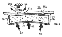
図4は、以下に述べる相違点を除いて第1の実施形態に非常に類似した第2の実施形態を示す。図4を参照して、ポート32は、ポート32を通って流体流動を制御するためにの流体流動制御デバイス60を有して提供される。流体流動制御デバイス60は、ポート32を通る流体の吸入(流入)および放出(排出)の両方を制御するか、またはただ一方向のみにおける流動を制御するように構成され得る。図4に示される第2の実施形態において、流体充填シール20は単一のポート32を備える。図5に示される後述の第3の実施形態において、流体充填シール20は第1ならびに第2のポート32aおよび32bを備え、流体流動制御デバイス60の機能は、2つのポート32a、32bに対するそれぞれのデバイス60a、60bの間に割り当てられる。
FIG. 4 shows a second embodiment that is very similar to the first embodiment except for the differences described below. Referring to FIG. 4, a
図4を参照して、流体流動制御デバイス60は、チャンバー36内の流体圧力を大気圧と等しくするためにチャンバー36に出入りし得る流体の度合いを制御するので、流体流動制御デバイス60は、発泡体38によって加えられる弾力における制動作用を制御し得る。流体流動制御デバイス60は吸入口および排出口の両方の方向に同一の流体流動特性を提供し得る。あるいは、流体流動制御デバイス60は、排出口の流体流動特性とは異なる吸入口の流体流動特性を提供し得る。
With reference to FIG. 4, the fluid
流体流動特性は、(i)ポート32の流体流動抵抗、および(ii)バルブ動作のうちの1つまたは両方を含む。バルブ動作は、バルブが開いて流動を可能にする吹出し圧力が一方向か二方向かによって、および、バルブが一旦最初に開くと恒久的に開き続けるか再び閉じるかによって規定され得る。
Fluid flow characteristics include one or both of (i) fluid flow resistance of
例えば、流体流動制御デバイス60は、吸入口の流体流量を流動のくびれによって制限し得る。1つの形態において、流体充填シール20への流動の制限は、流体充填シール20内に含まれる発泡体38の拡張作用のもとで、流体充填シール20をよりゆっくり膨張させ得る。これが、流体充填シール20がストーマ12の収縮にゆっくり応答することを可能にし得る。例えば、無制限の吸入口ポート32はシールが完全に圧縮された状態から10秒未満で完全に膨張することを可能にするのに対し、流体流動制御デバイス60は膨張時間を30分以上に変化させ得る。
For example, the fluid
別の実施形態において、流体流動制御デバイス60は、チャンバー36からの流体放出を可能にするよりも容易にチャンバー36への流体吸入を可能にするように構成される。流体流動制御デバイス60は、(i)吸入口の方向に、バルブを横切る比較的低い差圧(例えば、9mmHg以下の吹出し圧力)で開くように、および/または(ii)吸入口の方向の比較的低い流体流動抵抗(例えば、50cc/min以上の気流)を提供するように構成されるバルブ(図示されていない)を備える。これは、ストーマ12が皮膚表面に対して内側に移動するときに、柔軟な膜34がストーマ12の移動に迅速に合致することを可能にする。発泡体38および柔軟な膜34の膨張が実質的に制動されないように、流体はチャンバー36内に迅速に吸込まれ得る。対照的に、流体流動制御デバイス60は、排出口の方向に、吸入口の方向よりも高いバルブを横切る差圧(例えば、約15mmHgの吹出し圧力)で開くように、および/または排出口の方向に、吸入口の方向よりも比較的高い流体流動抵抗(例えば、3cc/min)を提供するように構成される。そのような特性は、ストーマ12が皮膚表面に対して外側に移動するときに、流体充填シール20内の変化を制動し、長く続く接触圧増加を回避するよう流体圧力をさらに管理する。これは、流体充填シール20が大便の圧力のもとでストーマ12からの暫時の難題を取り扱うことを可能にする。大便の圧力のもとでストーマ12が外側に移動するとき、チャンバー36に閉じ込められた流体は、ストーマ12に対する接触圧力を増加させる増加流体圧力になる。増加接触圧力は大便の放出を一時的に阻止することを支援し得る。しかしながら、流体流動制御デバイス60は、増加させられた流体圧力が長時間にわたってまたはある制限内で軽減されるような制動された応答で流体がチャンバー36から排出されることを可能にすることにより、所望よりも高い接触圧力が長時間にわたって維持されないことを確実にし、その結果、血液灌流を減じる結果として組織損傷のリスクがほとんどなくなる。
In another embodiment, the fluid
第2の実施形態において、流体流動制御デバイス60が示され、流体流動制御デバイス60は吸入口および排出口の両方の機能を実行する。図5に示される第3の実施形態において、流体充填シール20は第1および第2のポート32a、32bを備え、各々はそれぞれの流動制御である、第1の流動制御60a、第2の流動制御60bを有する。流動制御60a、60bのうちの1つまたは両方は二方向流動を可能にし得、または流動制御60a、60bのうちの1つまたは両方はただ一方向の流動を可能にし得る。図示された形態において、第1のポート32aは吸入口ポートとして働き、第1の流動制御60aはチャンバー36への流体流入を制御するため(およびポート32aを通っての流体排出を阻止するため)に構成される吸入バルブを備える。第2のポート32bは排出口ポートとして働き、第2の流動制御60bはチャンバー36からの流体排出を制御する(ポート32bを通っての流体吸入を阻止する)ために構成される排出バルブを備える。例えば、ストーマ12が矢印62に示されるように外側の方向に移動するとき、第2の流動制御60bは(矢印64に示される)流体の排出を制御し、上述のように制動された応答の流体充填シール20を提供する。
In a second embodiment, a fluid
流体流動制御デバイス60、および流動制御60a、60bは任意の適切な様式であり得、図6から図15に実施例が示される。
The fluid
図6は、1つ以上の取り付け領域68によってポート32を覆って支持壁30に取り付けられたシールフラップ66を概して備えるフラップバルブ65を示す。支持壁30のフラップ側とは反対側の流体圧力が支持壁30のフラップ側の圧力をバルブ閾値だけ越えるとき、フラップ66は流体がポート32を通過することを可能にするために支持壁30から持ち上がる。支持壁30のフラップ側の圧力の方が大きいとき、流体はフラップ66を押して支持壁30とシール接触するよう動かし、ポート32を通る流体流動を防止する。
FIG. 6 shows a flap valve 65 generally comprising a
図7はダックビル形式のバルブ69を示し、ダックビル形式のバルブ69が対面するリップを備えることを除いて同様の方法で作動する。
FIG. 7 shows a duckbill-
図8は、支持壁30にしっかりと固定された中央のステム74によって支持されたスカート76を備えるアンブレラバルブ72を示す。支持壁30のスカート側とは反対側の流体圧力が支持壁30のスカート側の圧力をバルブ閾値だけ越えるとき、スカート76は矢印78に示されるようにポート開口32の流体通過を可能にするために支持壁30から持ち上がる。支持壁30のスカート側の流体圧力が支持壁30の反対側のそれより大きいとき、流体はスカート76を押して支持壁30とシール係合するようにスカート76を押し付け、それによりポート開口32を通る流体流動を阻止する。
FIG. 8 shows an
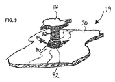
図9は、スプリング82によってポート32の台座とシール係合をするように押し付けられるボール80を備えるボールバルブ79を示す。支持壁30の反対側の流体圧力がスプリング力によって設定された値を越えるとき、圧力はボール80をポート32の台座とのシール係合から少し持ち上げ、矢印84に示されるように流体がポート32を通過するのを可能にする。支持壁30の反対側の流体圧力がバルブ閾値よりも降下すると、スプリング82はボール80をシール係合させてポート32を閉じる。
FIG. 9 shows a
図10は、図9のボールバルブに類似のポペットバルブ85を示すが、バルブ部材がボール80でなくポペットヘッド86であることが異なる。 FIG. 10 shows a poppet valve 85 similar to the ball valve of FIG. 9, except that the valve member is a poppet head 86 instead of a ball 80.
図11は、多孔性膜88、例えば、微孔性膜の形態をとる、ポート32に対する流動制限部材を示す。多孔性膜88は、ポート32の周りで支持壁30の表面に固着され、ポート32を通過する流体の流量を制御する。流動制限部材は、バルブとの組み合わせで用いられ得、または、ポート32はバルブがなく流動制限部材を除いて開放状態とされ得る。例えば、図5の実施形態において、放出バルブ60bは流動制限部材に置換され得る。これにより、恒久的に開放だが実質的な制限流量を有するポート32bが提供され得る。流体は、吸入バルブ60aによってチャンバー36になお迅速に吸入され得るが、チャンバー36から排出される気体は流動制限部材を通過しなくてはならず、それにより放出バルブ60bを必要とせずに第3の実施形態に対して説明されたように制動された応答を提供する。
FIG. 11 shows a flow restricting member for the
あるいは、図5の流動制御デバイス60は、流動制御デバイス60が閉じられているときでも低流量の流動を可能にするために多孔性膜88と適合され得る。
Alternatively, the
図12は、ポート32に配置される多孔性プラグ90の形態をとる代替の流動制限部材を示す。プラグ90は、例えば、微孔性材料から構成される。
FIG. 12 shows an alternative flow restricting member in the form of a
図13は、「漏れやすい」または不完全なシール特性を有するように修正された流動制御デバイス60を示す。流体流動制御デバイス60は、図6に示されるフラップバルブ65に基づいているが、同様の原理が任意の他のバルブに適用され得る。不完全なシールは、(i)遮断されたまたは織地表面を有するバルブ台座表面の少なくとも1つの部分94、(ii)バルブ台座表面を少なくとも部分的に横切る方向に延びる正確な溝または引っかき傷96、および/または(iii)流体が漏れることを可能にするシールフラップ66そのものの中の小孔、のうちの1つ以上によって提供される。3つの不完全なシールすべてが図13に組み合わせで示されるが、所望に応じて任意の2つまたは1つの特徴が実施され得ることが理解される。
FIG. 13 shows a
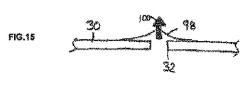
図14および図15は、チャンバー内の流体圧力が閾値を越えるようなポート32の恒久的および急激な開放に対する安全弁を示す。安全弁は、ポート32にわたってまたは横切って広がる破裂可能な膜98を備える。(矢印100で示される)圧力が膜98の破裂圧力を越えるとき、膜98は破裂して恒久的にポート32を開放し、流体の流出を可能にする。
14 and 15 show a safety valve against permanent and sudden opening of
前述の実施形態において、流体充填シール20はポート32を通って外気と連絡する単一のチャンバー36を備える。前述の実施形態に用いられる膨張流体は空気である。図16から図18は、流体の貯蔵所として作用する第2のチャンバー102を備える第4の実施形態を示し、第2のチャンバー102は少なくとも1つのポート32を通って、第1のチャンバー36と連絡する。第1および第2のチャンバー36、102は、少なくとも使用中は閉じたシステムを形成する。第1および第2のチャンバー36、102に含まれる流体は、空気または他の気体であり得、またはそれは生理食塩水または流動可能なジェルのような液体であり得る。第2のチャンバー102は、異なる弾力性のような、第1のチャンバー36とは異なる特性を有する。第1のチャンバー36の拡張および収縮を補償するように、流体は1つのチャンバーから他のチャンバーに自由に移動可能であり得る。これは、柔軟な膜34に加えられる力に、2つのチャンバー36、102間で液体を移動することによって反応するような応答システムを生成し得る。容量および圧力の特性は、外力によって喚起される第1のチャンバー36の容量および圧力における変化を決定する。そのため、第2のチャンバー102の特性は、変化する状態下で柔軟な膜34に作用する第1のチャンバー36の制御流体圧力を維持するために、選択または最適化され得る。
In the foregoing embodiment, the fluid-filled
図16から図18に示される形態において、第1および第2のチャンバー36、102間の流体移動は、1つ以上の流動制御60a、60bによって制御される。流動制御60a、60bは前述の任意のバルブおよび/または流動制限部材に類似のものであり得る。前述したものと類似の態様で、第2のチャンバー102から第1のチャンバー36への流体流動は相対的に無制限(無制動)であり、それに対して第1のチャンバー36から第2のチャンバー102への帰りの流体流動は第2の流動制御60bによって圧力リリーフ弁および/または流動制限部材(制動応答)の形態で制御され得る。
In the configurations shown in FIGS. 16-18, fluid movement between the first and
前述の説明は本発明の好ましい形態の例示であり、多くの修正が特許請求される本発明の範囲および/または原理から逸脱することなくなされ得ることが理解される。 It is understood that the foregoing description is illustrative of preferred forms of the invention, and that many modifications may be made without departing from the scope and / or principles of the claimed invention.
Claims (23)
流体チャンバーであって、該流体チャンバーの移動可能な壁を形成する流体不浸透性膜を含む流体チャンバーと、
該チャンバーと連絡する1つ以上のポートと、
該流体チャンバー内に配置されると共に、該流体チャンバーに概してぴったり合う寸法に作られている弾力性デバイスと
を有する、装具。 An excretion control ostomy appliance comprising a fluid filled seal that seals against a human body, the seal comprising
A fluid chamber comprising a fluid impermeable membrane forming a movable wall of the fluid chamber;
One or more ports in communication with the chamber;
An appliance having a resilient device disposed within the fluid chamber and dimensioned to generally fit the fluid chamber .
Applications Claiming Priority (3)
| Application Number | Priority Date | Filing Date | Title |
|---|---|---|---|
| US96809907P | 2007-08-27 | 2007-08-27 | |
| US60/968,099 | 2007-08-27 | ||
| PCT/US2008/074295 WO2009029610A1 (en) | 2007-08-27 | 2008-08-26 | Fluid filled seal for contacting the human body |
Publications (2)
| Publication Number | Publication Date |
|---|---|
| JP2010537734A JP2010537734A (en) | 2010-12-09 |
| JP5367709B2 true JP5367709B2 (en) | 2013-12-11 |
Family
ID=40387744
Family Applications (1)
| Application Number | Title | Priority Date | Filing Date |
|---|---|---|---|
| JP2010523085A Expired - Fee Related JP5367709B2 (en) | 2007-08-27 | 2008-08-26 | Fluid-filled seal that contacts the human body |
Country Status (12)
| Country | Link |
|---|---|
| US (1) | US20110040269A1 (en) |
| EP (1) | EP2185110B1 (en) |
| JP (1) | JP5367709B2 (en) |
| AU (1) | AU2008293614A1 (en) |
| CA (1) | CA2695681C (en) |
| ES (1) | ES2583009T3 (en) |
| HR (1) | HRP20160839T1 (en) |
| HU (1) | HUE029727T2 (en) |
| MX (1) | MX2010001840A (en) |
| PL (1) | PL2185110T3 (en) |
| PT (1) | PT2185110T (en) |
| WO (1) | WO2009029610A1 (en) |
Cited By (1)
| Publication number | Priority date | Publication date | Assignee | Title |
|---|---|---|---|---|
| US11771585B2 (en) | 2018-01-19 | 2023-10-03 | Ostovalve, Llc | Devices, systems and methods for regulating flow from a stoma on a patient |
Families Citing this family (32)
| Publication number | Priority date | Publication date | Assignee | Title |
|---|---|---|---|---|
| US8926577B2 (en) | 2006-10-17 | 2015-01-06 | C. R. Bard, Inc. | Waste management system |
| US8777912B2 (en) | 2007-07-22 | 2014-07-15 | C. R. Bard, Inc. | Waste management system |
| RU2519961C2 (en) | 2008-11-19 | 2014-06-20 | Конватек Текнолоджиз Инк. | Ileostomy bag |
| US8864729B2 (en) | 2009-07-14 | 2014-10-21 | Stimatix Gi Ltd. | Ostomy closure |
| KR101765350B1 (en) * | 2009-09-11 | 2017-08-07 | 컨바텍 테크놀러지스 인크 | Controlled discharge ostomy appliance and shield therefor |
| CN102834074B (en) | 2010-02-01 | 2016-06-15 | 赛义德·萨比特 | Medical treatment device |
| US10130506B2 (en) | 2010-03-02 | 2018-11-20 | Ostosolutions, LLC | Closure system for an ostomy pouch and related methods |
| US8690848B2 (en) * | 2010-03-02 | 2014-04-08 | Ostosolutions, LLC | Closure for ostomy pouch and method thereof |
| WO2011110140A1 (en) * | 2010-03-09 | 2011-09-15 | Werner Hamel | Sound absorber system for persons having a stoma for suppressing intestine exit noises |
| US8460259B2 (en) | 2010-11-02 | 2013-06-11 | Convatec Technologies, Inc. | Controlled discharge ostomy appliance and moldable adhesive wafer |
| WO2013016275A1 (en) | 2011-07-22 | 2013-01-31 | Cook Medical Technologies Llc | Irrigation devices adapted to be used with a light source for the identification and treatment of bodily passages |
| AU2013235386B2 (en) | 2012-03-19 | 2016-12-08 | Cook Medical Technologies Llc | Medical devices, methods and kits for delivering medication to a bodily passage |
| CN105407841B (en) | 2012-05-10 | 2018-10-30 | B·布劳恩医学股份有限公司 | Ostomy appliance |
| US9314593B2 (en) | 2012-09-24 | 2016-04-19 | Cook Medical Technologies Llc | Medical devices for the identification and treatment of bodily passages |
| CN105163694B (en) | 2012-11-20 | 2017-06-20 | 康沃特克科技公司 | Single type neostomy pouch reinforcer |
| WO2014134257A1 (en) | 2013-02-28 | 2014-09-04 | Cook Medical Technologies Llc | Medical devices, systems, and methods for the visualization and treatment of bodily passages |
| BR112015028183A2 (en) * | 2013-05-09 | 2020-06-30 | Stimatix Gi Ltd | ostomy device and cap |
| EP3024424B1 (en) | 2013-07-23 | 2022-10-19 | ConvaTec Technologies Inc. | Moldable adhesive wafers |
| US20150094675A1 (en) * | 2013-10-01 | 2015-04-02 | Tidi Securement Products, Llc | Stoma Stopper Securement Dressing |
| EP3099276B1 (en) | 2014-01-28 | 2018-01-24 | Hollister Incorporated | Ostomy faceplate including invertible stoma collar |
| US9937323B2 (en) | 2014-02-28 | 2018-04-10 | Cook Medical Technologies Llc | Deflectable catheters, systems, and methods for the visualization and treatment of bodily passages |
| US10195398B2 (en) | 2014-08-13 | 2019-02-05 | Cook Medical Technologies Llc | Tension member seal and securing mechanism for medical devices |
| US11426302B2 (en) * | 2014-11-03 | 2022-08-30 | Fistula Solution Corporation | Containment devices for treatment of intestinal fistulas and complex wounds |
| EP3215198B1 (en) * | 2014-11-03 | 2021-04-28 | Fistula Solution Corporation | Containment devices for treatment of intestinal fistulas and complex wounds |
| GB201610527D0 (en) | 2016-06-16 | 2016-08-03 | Ostomycure As | Lid |
| USD818590S1 (en) | 2016-06-16 | 2018-05-22 | Ostomycure As | Lid for a medical implant |
| USD1012280S1 (en) | 2018-11-30 | 2024-01-23 | B. Braun Medical Sas | Ostomy device assembly |
| US11207097B2 (en) | 2019-02-13 | 2021-12-28 | Andrew Thomas Obst | Fluid management device for medical tubes and drainage incisions |
| US11523932B2 (en) | 2019-06-26 | 2022-12-13 | Andrew Thomas Obst | Enteric fistula, rectovaginal fistula, and ostomy effluent containment system, and devices and methods thereof |
| CN111152942B (en) * | 2020-01-06 | 2021-09-07 | 北京卫星环境工程研究所 | Space debris protection system |
| EP4267053A1 (en) * | 2020-12-28 | 2023-11-01 | ConvaTec Technologies Inc. | Non-collapsible catheter tube |
| AU2023206214B1 (en) | 2022-06-22 | 2023-08-31 | Hollister Incorporated | Dynamic convex ostomy barrier |
Family Cites Families (10)
| Publication number | Priority date | Publication date | Assignee | Title |
|---|---|---|---|---|
| US3595240A (en) * | 1968-08-07 | 1971-07-27 | Alan J Mishler | Hydrocephalus shunt with two-way flushing means |
| DK2789D0 (en) * | 1989-01-04 | 1989-01-04 | Bar Shalom Daniel | CLOSING FACILITIES FOR COATING |
| US6033390A (en) * | 1998-02-25 | 2000-03-07 | Zassi Medical Evolutions, Inc. | Continent ostomy port |
| TW455482B (en) * | 1998-07-30 | 2001-09-21 | David Lubowski | Sigmoidoscope |
| GB9904527D0 (en) * | 1999-02-26 | 1999-04-21 | Bristol Myers Squibb Co | Ostomy appliance |
| US6689111B2 (en) * | 2002-03-22 | 2004-02-10 | Bristol-Myers Squibb Company | Controlled evacuation ostomy device with internal seal |
| US6723079B2 (en) * | 2002-03-27 | 2004-04-20 | Bristol-Myers Squibb Company | Controlled evacuation ostomy device with external seal |
| NZ551481A (en) * | 2005-11-30 | 2008-08-29 | Bristol Myers Squibb Co | Controlled evacuation ostomy appliance |
| US8142406B2 (en) * | 2005-12-07 | 2012-03-27 | Convatec Technologies Inc. | Ostomy coupling |
| US8070737B2 (en) * | 2006-01-06 | 2011-12-06 | Convatec Technologies Inc. | Seal for controlled evacuation ostomy appliance |
-
2008
- 2008-08-26 EP EP08798686.5A patent/EP2185110B1/en active Active
- 2008-08-26 PL PL08798686.5T patent/PL2185110T3/en unknown
- 2008-08-26 JP JP2010523085A patent/JP5367709B2/en not_active Expired - Fee Related
- 2008-08-26 AU AU2008293614A patent/AU2008293614A1/en not_active Abandoned
- 2008-08-26 HU HUE08798686A patent/HUE029727T2/en unknown
- 2008-08-26 PT PT87986865T patent/PT2185110T/en unknown
- 2008-08-26 MX MX2010001840A patent/MX2010001840A/en active IP Right Grant
- 2008-08-26 US US12/675,530 patent/US20110040269A1/en not_active Abandoned
- 2008-08-26 CA CA2695681A patent/CA2695681C/en not_active Expired - Fee Related
- 2008-08-26 WO PCT/US2008/074295 patent/WO2009029610A1/en active Application Filing
- 2008-08-26 ES ES08798686.5T patent/ES2583009T3/en active Active
-
2016
- 2016-07-12 HR HRP20160839TT patent/HRP20160839T1/en unknown
Cited By (1)
| Publication number | Priority date | Publication date | Assignee | Title |
|---|---|---|---|---|
| US11771585B2 (en) | 2018-01-19 | 2023-10-03 | Ostovalve, Llc | Devices, systems and methods for regulating flow from a stoma on a patient |
Also Published As
| Publication number | Publication date |
|---|---|
| HUE029727T2 (en) | 2017-03-28 |
| US20110040269A1 (en) | 2011-02-17 |
| MX2010001840A (en) | 2010-03-11 |
| PT2185110T (en) | 2016-07-25 |
| PL2185110T3 (en) | 2016-10-31 |
| EP2185110B1 (en) | 2016-07-06 |
| CA2695681C (en) | 2016-02-02 |
| EP2185110A1 (en) | 2010-05-19 |
| EP2185110A4 (en) | 2015-01-07 |
| CA2695681A1 (en) | 2009-03-05 |
| AU2008293614A1 (en) | 2009-03-05 |
| JP2010537734A (en) | 2010-12-09 |
| ES2583009T3 (en) | 2016-09-16 |
| WO2009029610A1 (en) | 2009-03-05 |
| HRP20160839T1 (en) | 2016-09-23 |
Similar Documents
| Publication | Publication Date | Title |
|---|---|---|
| JP5367709B2 (en) | Fluid-filled seal that contacts the human body | |
| EP1792590B1 (en) | Controlled evacuation ostomy appliance | |
| EP1637100B1 (en) | Controlled evacuation ostomy appliance | |
| CA2517997C (en) | Stoma plug | |
| CA2573158C (en) | Seal for controlled evacuation ostomy appliance | |
| CA2804352C (en) | Drainage appliance for body waste | |
| US9078764B2 (en) | Stoma closure | |
| JP5410976B2 (en) | Composite cushion with valve regulated by compression and valve assembly therefor | |
| AU2014221232B2 (en) | Fluid filled seal for contacting the human body | |
| EP4322894A2 (en) | Catheter system with pressure management device | |
| AU2011247843B2 (en) | Seal for controlled evacuation ostomy appliance | |
| AU2011247847B2 (en) | Stoma plug |
Legal Events
| Date | Code | Title | Description |
|---|---|---|---|
| A621 | Written request for application examination |
Free format text: JAPANESE INTERMEDIATE CODE: A621 Effective date: 20110802 |
|
| A521 | Request for written amendment filed |
Free format text: JAPANESE INTERMEDIATE CODE: A523 Effective date: 20120720 |
|
| A131 | Notification of reasons for refusal |
Free format text: JAPANESE INTERMEDIATE CODE: A131 Effective date: 20121212 |
|
| A601 | Written request for extension of time |
Free format text: JAPANESE INTERMEDIATE CODE: A601 Effective date: 20130307 |
|
| A602 | Written permission of extension of time |
Free format text: JAPANESE INTERMEDIATE CODE: A602 Effective date: 20130314 |
|
| RD03 | Notification of appointment of power of attorney |
Free format text: JAPANESE INTERMEDIATE CODE: A7423 Effective date: 20130322 |
|
| RD04 | Notification of resignation of power of attorney |
Free format text: JAPANESE INTERMEDIATE CODE: A7424 Effective date: 20130329 |
|
| A601 | Written request for extension of time |
Free format text: JAPANESE INTERMEDIATE CODE: A601 Effective date: 20130411 |
|
| A602 | Written permission of extension of time |
Free format text: JAPANESE INTERMEDIATE CODE: A602 Effective date: 20130418 |
|
| A601 | Written request for extension of time |
Free format text: JAPANESE INTERMEDIATE CODE: A601 Effective date: 20130508 |
|
| A602 | Written permission of extension of time |
Free format text: JAPANESE INTERMEDIATE CODE: A602 Effective date: 20130515 |
|
| A521 | Request for written amendment filed |
Free format text: JAPANESE INTERMEDIATE CODE: A523 Effective date: 20130611 |
|
| TRDD | Decision of grant or rejection written | ||
| A01 | Written decision to grant a patent or to grant a registration (utility model) |
Free format text: JAPANESE INTERMEDIATE CODE: A01 Effective date: 20130820 |
|
| A61 | First payment of annual fees (during grant procedure) |
Free format text: JAPANESE INTERMEDIATE CODE: A61 Effective date: 20130911 |
|
| R150 | Certificate of patent or registration of utility model |
Ref document number: 5367709 Country of ref document: JP Free format text: JAPANESE INTERMEDIATE CODE: R150 Free format text: JAPANESE INTERMEDIATE CODE: R150 |
|
| R250 | Receipt of annual fees |
Free format text: JAPANESE INTERMEDIATE CODE: R250 |
|
| R250 | Receipt of annual fees |
Free format text: JAPANESE INTERMEDIATE CODE: R250 |
|
| R250 | Receipt of annual fees |
Free format text: JAPANESE INTERMEDIATE CODE: R250 |
|
| R250 | Receipt of annual fees |
Free format text: JAPANESE INTERMEDIATE CODE: R250 |
|
| R250 | Receipt of annual fees |
Free format text: JAPANESE INTERMEDIATE CODE: R250 |
|
| R250 | Receipt of annual fees |
Free format text: JAPANESE INTERMEDIATE CODE: R250 |
|
| LAPS | Cancellation because of no payment of annual fees |