JP5367593B2 - Gas insulated bus - Google Patents
Gas insulated bus Download PDFInfo
- Publication number
- JP5367593B2 JP5367593B2 JP2010005010A JP2010005010A JP5367593B2 JP 5367593 B2 JP5367593 B2 JP 5367593B2 JP 2010005010 A JP2010005010 A JP 2010005010A JP 2010005010 A JP2010005010 A JP 2010005010A JP 5367593 B2 JP5367593 B2 JP 5367593B2
- Authority
- JP
- Japan
- Prior art keywords
- conductor
- gas
- contact
- axial direction
- insulated bus
- Prior art date
- Legal status (The legal status is an assumption and is not a legal conclusion. Google has not performed a legal analysis and makes no representation as to the accuracy of the status listed.)
- Active
Links
Images

Classifications
-
- H—ELECTRICITY
- H02—GENERATION; CONVERSION OR DISTRIBUTION OF ELECTRIC POWER
- H02G—INSTALLATION OF ELECTRIC CABLES OR LINES, OR OF COMBINED OPTICAL AND ELECTRIC CABLES OR LINES
- H02G5/00—Installations of bus-bars
- H02G5/06—Totally-enclosed installations, e.g. in metal casings
- H02G5/061—Tubular casings
-
- H—ELECTRICITY
- H02—GENERATION; CONVERSION OR DISTRIBUTION OF ELECTRIC POWER
- H02G—INSTALLATION OF ELECTRIC CABLES OR LINES, OR OF COMBINED OPTICAL AND ELECTRIC CABLES OR LINES
- H02G5/00—Installations of bus-bars
- H02G5/002—Joints between bus-bars for compensating thermal expansion
-
- H—ELECTRICITY
- H02—GENERATION; CONVERSION OR DISTRIBUTION OF ELECTRIC POWER
- H02G—INSTALLATION OF ELECTRIC CABLES OR LINES, OR OF COMBINED OPTICAL AND ELECTRIC CABLES OR LINES
- H02G5/00—Installations of bus-bars
- H02G5/06—Totally-enclosed installations, e.g. in metal casings
- H02G5/066—Devices for maintaining distance between conductor and enclosure
Landscapes
- Installation Of Bus-Bars (AREA)
- Gas-Insulated Switchgears (AREA)
Description
本発明は、密閉容器の内部に通電用導体を収納するとともにSF6ガス等の絶縁性能に優れたガスを充填してなるガス絶縁母線に係り、特に、導体接続部に変位吸収用伸縮継手を有するガス絶縁母線に関するものである。 The present invention relates to a gas-insulated bus in which a current-carrying conductor is housed in an airtight container and is filled with a gas having excellent insulation performance such as SF 6 gas, and in particular, a displacement-absorbing expansion joint is provided at a conductor connecting portion. The present invention relates to a gas-insulated bus bar.
ガス絶縁母線は、ガス絶縁開閉装置(GIS)で使用されており、通電用導体(以下、単に導体という)を円筒形の金属性の密閉容器の内部に絶縁支持して構成されている。ガス絶縁母線の密閉容器および導体は、周囲の温度変化、日射、および内部導体電流による発熱、温度上昇等によって熱伸縮する。また、地震発生時にはガス絶縁母線の位置と基礎を固定している位置とが相対的に変位して、密閉容器が伸縮させられることになる。 The gas insulated bus is used in a gas insulated switchgear (GIS), and is configured by insulatingly supporting a current-carrying conductor (hereinafter simply referred to as a conductor) inside a cylindrical metal hermetic container. The sealed container and the conductor of the gas insulated bus are thermally expanded and contracted by ambient temperature change, solar radiation, heat generation due to internal conductor current, temperature rise, and the like. In addition, when an earthquake occurs, the position of the gas insulated bus and the position where the foundation is fixed are relatively displaced, and the sealed container is expanded and contracted.
密閉容器の伸縮量は、次式で示されている。すなわち、
(熱伸縮量)=(密閉容器の線膨脹係数)×(固定間距離)×(温度変化)
したがって、固定間距離が長く、かつ夏場のように気温の高い季節では、熱伸縮量が非常に大きくなり、ガス絶縁母線に過大な荷重が発生し、構成機器が損傷を受ける可能性がある。
The expansion / contraction amount of the sealed container is expressed by the following equation. That is,
(The amount of thermal expansion and contraction) = (Linear expansion coefficient of the sealed container) x (distance between fixed points) x (temperature change)
Therefore, in a season with a long fixed distance and a high temperature such as summer, the amount of thermal expansion and contraction becomes very large, an excessive load is generated on the gas insulated bus, and the component equipment may be damaged.
従来、このような密閉容器の伸縮に起因する機器の損傷を防止するために、ガス絶縁母線の密閉容器の一部に伸縮可能な伸縮継手(ベローズ)を挿入してこのような伸縮量を吸収するようにしている(例えば、特許文献1、2参照)。 Conventionally, in order to prevent damage to the equipment due to such expansion and contraction of the sealed container, a stretchable expansion joint (bellows) is inserted into a part of the sealed container of the gas insulated bus to absorb such expansion and contraction. (For example, refer to Patent Documents 1 and 2).
なお、密閉容器の伸縮を念頭においた技術ではないが、ガス絶縁開閉装置の組立やメンテナンスを容易に行うために、密閉容器の相互間を伸縮継手によって接続したものもある(例えば、特許文献3参照)。 Although this is not a technique with the expansion and contraction of the sealed container in mind, there is a technique in which the sealed containers are connected to each other by an expansion joint in order to easily assemble and maintain the gas insulated switchgear (for example, Patent Document 3). reference).
上記特許文献1および2には、コーン形絶縁スペーサの埋め込み電極(埋め込み導体)に接続された接触子と導体との相互の接続構造については開示されていないが、特許文献3には伸縮継手と集電子を介して絶縁スペーサの両側の導体相互間を接続する構造が開示されている。
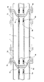
以下説明する図9は、特許文献3に開示されている構造と同一ではないが、類似する構造のガス絶縁母線による導体接続構造を示す図である。 FIG. 9 to be described below is a diagram showing a conductor connection structure using a gas insulated bus having a similar structure, although it is not the same as the structure disclosed in Patent Document 3.
なお、ガス絶縁母線は、特許文献3のように密閉容器の内部に導体を3つ収納した三相ガス絶縁母線と、導体を1つだけ収納した単相ガス絶縁母線との2種類が用いられるが、以下の説明では、単相ガス絶縁母線について説明する。 Note that two types of gas-insulated buses are used: a three-phase gas-insulated bus with three conductors housed in a sealed container and a single-phase gas-insulated bus with only one conductor as in Patent Document 3. However, in the following description, a single-phase gas insulated bus will be described.
図9において、接地電位に保持された円筒形の金属性の密閉容器1は、内部に中空状の導体2を同心状に配置しており、かつ、両端部のフランジにボルト・ナットによってそれぞれ伸縮継手3a、3bの一端のフランジを固定している。
In FIG. 9, a cylindrical metallic sealed container 1 maintained at a ground potential has
両端の伸縮継手3a、3bの他端フランジはそれぞれボルト・ナットによってコーン形絶縁スペーサ4a、4bに固定されるようになっている。このコーン形絶縁スペーサ4a、4bの中心部に位置する埋め込み電極(導体)4cの両側にはそれぞれロッド状の接触子5a、5bが溶接等により一体的に接続されている。
The other end flanges of the
また、密閉容器1の内部に収納された前記導体5は、その両端部の内周部に設けた軸方向(長手方向)に摺動可能なスライドコンタクト導電部6a、6bを介して前記ロッド状の接触子5a、5bと電気的に接続されるようになっている。そして密閉容器1内部には、ガス絶縁母線の組立作業完了後にSF6ガス等の絶縁性能に優れた絶縁ガス7が充填されるようになっている。
The conductor 5 housed in the sealed container 1 is rod-shaped through slide contact
このように構成されたガス絶縁母線における導体接続構造には、熱膨張変位を吸収した状態においても導体の自重および短絡電流通電時の電磁力に耐える機械的強度、スライドコンタクト導電部の接触状態を保持して通電できる通電性能および絶縁破壊を起こさない絶縁性能等が要求される。 The conductor connection structure in the gas-insulated bus constructed in this way has the mechanical strength that can withstand the weight of the conductor and the electromagnetic force when the short-circuit current is applied even when the thermal expansion displacement is absorbed, and the contact state of the slide contact conductive part. Energization performance that can be held and energized and insulation performance that does not cause dielectric breakdown are required.
上述した従来のガス絶縁母線における導体接続構造では、図10に示すように母線の軸方向についてはスライドコンタクト導電部が軸方向に摺動して接触状態を保つので、コーン形絶縁スペーサ4a、4bに設けられた接触子5a、5bの摺動部長さに応じて軸方向の大変位については吸収が可能であった。
In the above-described conventional conductor connection structure in the gas-insulated bus, the slide contact conductive portion slides in the axial direction in the axial direction of the bus as shown in FIG. The large displacement in the axial direction can be absorbed in accordance with the length of the sliding portion of the
しかし、母線構成がL形等で、軸方向だけでなく軸方向と直行する直角方向にも大変位が生じる場合、軸方向用のスライドコンタクト導電部では軸直角方向に変位した状態で、通電・機械的強度を保てる変位角度(変位量)が小さかった。このため、軸方向変位吸収量のある大変位吸収用伸縮継手母線を変位の生じる方向ごとに2箇所設ける必要があり、そのため、伸縮継手母線の構造が複雑であった。 However, if the bus configuration is L-shaped and a large displacement occurs not only in the axial direction but also in a direction perpendicular to the axial direction, the sliding contact conductive part for the axial direction is The displacement angle (displacement amount) that can maintain the mechanical strength was small. For this reason, it is necessary to provide two large displacement-absorbing expansion joint buses having an axial displacement absorption amount for each direction in which displacement occurs, and the structure of the expansion joint bus is complicated.
そこで、本発明では、複雑な構造にならないで、軸方向だけでなく、軸直角方向の大変位をも吸収できるガス絶縁母線を提供することを目的とする。 Therefore, an object of the present invention is to provide a gas-insulated bus that can absorb not only a complicated structure but also a large displacement not only in the axial direction but also in a direction perpendicular to the axial direction.
上記の目的を達成するために、本発明の請求項1に係る発明は、絶縁ガスを封入した密閉容器の内部に導体を収納するとともに、当該導体の端部を絶縁スペーサで支持された接触子と電気的に接続するように構成されたガス絶縁母線において、前記導体の両端部に、それぞれ導体の軸方向と直交する方向の変位を吸収することが可能な接続部と、導体の軸方向の変位を吸収することが可能な接続部とを備え、前記導体の軸方向と直交する方向の変位を吸収することが可能な接続部を、ピン構造の回転摺動導電部で構成したことを特徴とする。 In order to achieve the above object, according to the first aspect of the present invention, a contact is accommodated in an airtight container filled with an insulating gas, and an end of the conductor is supported by an insulating spacer. In the gas-insulated bus configured to be electrically connected to each other, both end portions of the conductor each have a connection portion capable of absorbing displacement in a direction orthogonal to the axial direction of the conductor, and an axial direction of the conductor A connecting portion capable of absorbing the displacement, and the connecting portion capable of absorbing the displacement in the direction perpendicular to the axial direction of the conductor is constituted by a rotating sliding conductive portion having a pin structure. Features.
また、請求項7に係るガス絶縁母線の発明は、絶縁ガスを封入した密閉容器の内部に導体を収納するとともに、当該導体の端部を絶縁スペーサで支持された接触子と電気的に接続するように構成されたガス絶縁母線において、前記導体の両側にそれぞれ板状接触子を設けると共に、この板状接触子を軸方向および軸直角方向に摺動可能に挟持するスライドコンタクト導電部を前記絶縁スペーサで支持された接触子に固定したことを特徴とする。 In the gas insulated bus according to the seventh aspect of the invention, the conductor is housed in a sealed container filled with the insulating gas, and the end of the conductor is electrically connected to the contact supported by the insulating spacer. In the gas-insulated bus configured as described above, plate-like contacts are provided on both sides of the conductor, and the slide contact conductive portion that slidably holds the plate-like contacts in the axial direction and the direction perpendicular to the axis is insulated. It was fixed to the contactor supported by the spacer.
本発明のガス絶縁母線によれば、導体の両端に、導体の軸方向と直交する方向の変位を吸収する回転摺動導電部および導体の軸方向への変位を吸収するスライドコンタクト導電部を設けたので、軸方向だけでなく、軸方向と直交する方向の変位についても吸収することができ、かつ機械的強度・通電性能・絶縁性能を満足することができる。 According to the gas-insulated bus of the present invention, at both ends of the conductor, a rotational sliding conductive portion that absorbs displacement in a direction orthogonal to the axial direction of the conductor and a slide contact conductive portion that absorbs displacement in the axial direction of the conductor are provided. Therefore, not only the axial direction but also the displacement in the direction orthogonal to the axial direction can be absorbed, and the mechanical strength, current-carrying performance, and insulation performance can be satisfied.
以下、本発明に係るガス絶縁母線の実施形態について図面を参照して説明する。
なお、実施形態1乃至8のガス絶縁母線の場合も、従来技術の図9のように導体2を収容する密閉容器1やその両端部に伸縮継手3a、3bを設けているが、これらは発明の主要部ではないので図1乃至図8では図示を省略している。
また、各図を通して同一部分や対応する部分には同一符号を付けることにより、重複する説明は適宜省略する。
Hereinafter, embodiments of a gas insulated bus according to the present invention will be described with reference to the drawings.
In the case of the gas-insulated buses of Embodiments 1 to 8, the sealed container 1 that houses the
In addition, the same parts and corresponding parts are denoted by the same reference numerals throughout the drawings, and redundant description will be omitted as appropriate.
[実施形態1]
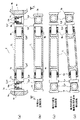
図1を参照して本実施形態1に係るガス絶縁母線について説明する。
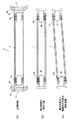
図1(a)乃至(g)において、本実施形態1に係る導体2は、構成部品を大別すると、中空状の中央部材21と、その両端に配置され前記中央部材21とコーン形絶縁スペーサ4a、4bに支持された接触子5a、5bとを接続する端部接続部材22a、22bと、これら中央部材21と端部接続部材22a、22bとが相対的に回転可能に連結接続するピン構造の連結接続部材23a、23bとから構成されている。
[Embodiment 1]
A gas insulated bus according to the first embodiment will be described with reference to FIG.
In FIGS. 1 (a) to (g), the
これらの構成部品のうち、まず、中央部材21から説明する。
中央部材21は、図1(c)で示すように中央部が中空の円柱状に形成されており、両端部には軸方向の中心線から外周面側に偏位した位置にそれぞれ接続片21a、21bを設けている。この接続片21a、21bには、それぞれ後述するピン構造の連結接続部材23a、23bを固定するためのボルト孔21hが2個ずつ開けてある。
Of these components, the
次に、端部接続部材22a、22bについて説明する。
端部接続部材22a、22bは、図1(d)で示すように一端をパイプ状接続片22a1、22b1として形成され、他端すなわちパイプ状接続片22a1、22b1の反対側は穴あき接続端子状の接続片(以下、端子状接続片という)22a2、22b2として形成している。
Next, the end connection members 2 2 a and 2 2 b will be described.
End connection member 2 2 a, 2 2 b is 1 one end as shown in (d) is formed as a pipe-
まず、パイプ状接続片22a1、22b1は、その内周面に軸方向に摺動可能なスライドコンタクト導電部6a、6bを固定し、このスライドコンタクト導電部6a、6bに電気的に接続するように接触子5a、5bを嵌入するようになっている。この接触子5a、5bは、前述したようにコーン形絶縁スペーサ4a、4bの埋め込み電極4cに接続され支持されている。
First, the pipe-like connecting
そして、これらのパイプ状接続片22a1、22b1と、スライドコンタクト導電部6a、6bと、接触子5a、5bとによって軸方向摺動用のスライドコンタクト導電部が構成される。
The pipe-shaped connecting
一方、端子状接続片22a2、22b2は、前記連結接続部材23a、23bのピン状接続片23pを嵌入するための穴22hを開けており、この穴の内周面には後述する回転方向に摺動可能なスライドコンタクト導電部9a、9bを固定し、このスライドコンタクト導電部9a、9bに電気的に接続するように後述するピン状接続片23pを嵌入するようになっている。
On the other hand, the terminal-like connecting piece 2 2 a2,2 2 b2 has a hole 2 2 h for fitting the coupling connecting member 2 3 a, 2 3 b pin-shaped connection piece 2 3 p of the hole the inner peripheral surface slidable in the direction of rotation to be described later to slide contact
次に、ピン構造の連結接続部材23a、23bについて説明する。
ピン構造の連結接続部材23a、23bは、図1(e)で示すように、端子状接続片22a2、22b2に開けた穴22hに嵌入され、ボルト10a、10bがねじ込まれるねじ孔を有するピン状接続片23pと、ねじ孔の反対側にピン頭部23dとを備えている。
Next, the pin connection connecting members 2 3 a and 2 3 b will be described.
As shown in FIG. 1 (e), the pin-type connecting and connecting members 2 3 a and 2 3 b are inserted into holes 2 2 h formed in the terminal-like connecting
そして、これらの端子状接続片22a2、22b2と、スライドコンタクト導電部9a、9bとピン状接続片23pとによって回転摺動導電部が構成される。
These terminal-
本実施形態1に係る導体2は次のようにして組み立てられる。
まず、端部接続部材22a、22bのパイプ状接続片22a1、22b1の内周面に固定されたスライドコンタクト導電部6a、6bと接触するように、コーン形絶縁スペーサ4a、4bの埋め込み電極4cに電気的に接続され支持されているロッド状の接触子5a、5bを嵌入する。この場合、ロッド状の接触子5a、5bと端部接続部材22a、22bとが軸方向にのみ摺動し、相対的に回転しないように回転止めピン8a、8bを差し込んでおく。
The
First, end connection member 2 2 a, 2 2 b of the pipe-shaped
この状態では、コーン形絶縁スペーサ4a、4bの埋め込み電極4c−ロッド状の接触子5a(5b)−スライドコンタクト導電部6a(6b)−パイプ状接続片22a1(22b1)が電気的に接続される。
In this state, the embedded
次に、端部接続部材22a、22bの端子状接続片22a2、22b2に開けた穴22hの内周面に固定された回転方向に摺動可能なスライドコンタクト導電部9a、9bと接触するように連結接続部材23aのピン状接続片23pを嵌入し、その状態で前記接続片21a、21bに開けたボルト孔21hからボルト10a、10bをねじ込むことにより接続片21a、21bとピン状接続片23pとを面接合状態で強く固定する。
Then, end connection member 2 2 a, 2 2 b terminals like connecting
この状態では、端子状接続片22a2(22b2)−スライドコンタクト導電部9a(9b)−ピン状接続片23p−接続片21a(21b)−中央部材21が電気的に接続される。
In this state, the terminal-
次に、図1(f)および(g)を参照して本実施形態1によるガス絶縁母線が軸方向の変位および軸と直交する方向の変位を吸収する様子を説明する。
図1(f)において、ガス絶縁母線の軸方向に大きな変位を生じた場合には、コーン形絶縁スペーサ3a、3bにそれぞれ支持されたロッド状の接触子5a、5bとパイプ状接続片22a1、22b1との間で、接触子5a、5bの摺動長に応じて軸方向の変位を吸収する。
Next, with reference to FIGS. 1 (f) and (g), description will be given of how the gas insulating bus according to the first embodiment absorbs the displacement in the axial direction and the displacement in the direction perpendicular to the axis.
In FIG. 1 (f), when a large displacement occurs in the axial direction of the gas insulating bus, rod-shaped
図1(g)において、ガス絶縁母線に軸方向と直交する方向の変位が生じた場合には、中央部材21と端部接続部材22a、22bとがピン構造の連結接続部材23a、23bを介して回転方向に摺動することができるので、軸方向と直交する方向の変位も吸収することができる。
In FIG. 1 (g), the when the displacement in the direction perpendicular to the axial direction to the gas insulated bus occurs, the
以上述べたように、本実施形態1によれば、導体2は、両端に導体の軸方向にスライドするスライドコンタクト導電部6a、6bおよび導体の軸方向と直交する方向に回転するピン構造の回転摺動導電部(9a、9b)を備えた連結接続部材23a、23bを設けたことにより、ガス絶縁母線の軸方向と直交する方向に生じた変位は、ピン構造の回転摺動導電部により吸収することができ、また、ガス絶縁母線の軸方向に生じた変位は、スライドコンタクト導電部6a、6bにより接触子5a、5bの摺動部長に応じて吸収することができ、いずれの方向の変位に対しても常にスライドコンタクト導電部の接触が保たれて通電性能を満足し、機械的強度を保ち、かつ、導体2が大変位した状態でも導体表面は連続的な面で構成されているため、絶縁性能は低下することはない。
As described above, according to the first embodiment, the
[実施形態2]
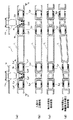
図2を参照して本実施形態2に係るガス絶縁母線について説明する。
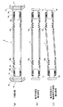
図2(a)乃至(d)において、本実施形態2に係る導体2は、構成部品を大別すると、中空状の中央部材21と、その両端に配置される端部接続部材24a、24bと、この端部接続部材24a、24bとコーン形絶縁スペーサ4a、4bに支持された接触子5a、5bとを接続する連結接続部材23a、23bとから構成されている。
[Embodiment 2]
A gas-insulated bus according to the second embodiment will be described with reference to FIG.
In FIGS. 2 (a) to (d), the
これらの構成部品のうち、まず、中央部材21から説明する。
中央部材21は、両端の中空部内周面に導体2の軸方向に摺動可能なスライドコンタクト導電部6a、6bを固定し、このスライドコンタクト導電部6a、6bに電気的に接続するように後述する前記端部接続部材24a、24bのロッド状の接続片24a2、24b2をそれぞれ挿入接続するようにしている。
Of these components, the
次に、端部接続部材24a、24bについて説明する。
この端部接続部材24a、24bは、一端に軸方向中心線から一方外周面側に偏位した接続片24a1、24b1を形成し、他端にロッド状の接続片24a2、24b2を形成している。このロッド状の接続片24a2、24b2は前述したように軸方向に摺動可能なスライドコンタクト導電部6a、6bを介して中央部材21の両端に形成された中空部に嵌入するようになっている。
Next, the end connection members 2 4 a and 2 4 b will be described.
The end connection members 2 4 a, 2 4 b are formed with
次に、接触子5a、5bと、連結接続部材23a、23bとの関係について説明する。
絶縁スペーサ4a、4cの埋め込み電極4cに電気的に接続され支持された接触子5a、5bは、前記実施形態1で説明した接触子5a、5bのようにロッド状には形成されておらず、図1(d)の端子状接続片22a2、22b2と同様の形状に形成されている。
Next, the relationship between the
The
そして、この接触子5a、5bに開けたピン挿入穴に回転摺動可能なスライドコンタクト導電部9a、9bを介してピン構造の連結接続部材23aを嵌め、接続片24a1、24b1側からボルト10a、10bをねじ込むことにより接続片24a1、24b1とピン状接続片23pとを面接触状態で強く締結する。
Then, fit the coupling connecting member 2 3 a pin structure via the
この結果、中心部材21と端部接続部材24a、24bとは導体2の軸方向に摺動可能なスライドコンタクト導電部6a、6bを介して電気的に接続され、また、端部接続部材24a、24bと、絶縁スペーサ4a、4bで支持された接触子5a、5bとは、ロッド状の接続片24a2、24b2、回転摺動可能なスライドコンタクト導電部9a、9bを介してピン構造の接続片23a、23bに電気的に接続される。
As a result, the
以上のように構成された本実施形態2によれば、実施形態1と同様に、導体2は、両端に導体の軸方向にスライドするスライドコンタクト導電部および導体の軸方向と直交する方向に回転するピン構造の回転摺動導電部を備えた連結接続部材を設けたことにより、軸直角方向の変位はピン部の回転摺動により、軸方向の変位はスライドコンタクト導電部6a、6bにより吸収でき、常にスライドコンタクト導電部の接触が保たれて通電性能を満足し、大変位した状態でも導体表面は連続的な面で構成されているため、絶縁性能は低下しない。また、ピン構造の回転摺動導電部を、絶縁スペーサ4a、4bで直接機械的に支持することで、回転摺動運動が安定する。
According to the second embodiment configured as described above, the
[実施形態3]
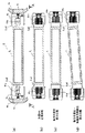
図3を参照して本実施形態3に係るガス絶縁母線について説明する。
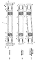
図3(a)乃至(d)において、本実施形態3に係る導体2は、構成部品を大別すると、中央部が中空に形成されており、両端部にロッド状の接触片21a1、21b1を備えた中央部材21と、この中央部材21のロッド状の接触片21a1、21b1に一端がそれぞれ接続される中間接続部材25a、25bと、この中間接続部材25a、25bの他端に接続される端部接続部材26a、26bと、前記中間接続部材25a、25bおよび端部接続部材26a、26bの接続部分を回転可能な状態にしてポスト形絶縁スペーサ11a、11bで支持するようにしたピン構造の連結接続部材23a、23bとから構成されている。
[Embodiment 3]
A gas-insulated bus according to the third embodiment will be described with reference to FIG.
3 (a) to 3 (d), the
前記中間接続部材25a、25bは、実施形態1で採用した端部接続部材22a、22bと同様に構成され一端にパイプ状接続片25a1、25b1を形成し、他端にピン挿入穴を有する端子状接続片25a2、25b2を形成している。
The intermediate connecting members 2 5 a, 2 5 b are configured in the same manner as the end connecting members 2 2 a, 2 2 b employed in the first embodiment, and pipe-shaped connecting
パイプ状接続片25a1、25b1の内周面には軸方向に摺動可能なスライドコンタクト導電部6a、6bを固定し、このスライドコンタクト導電部6a、6bと接触するように前記中央部材21のロッド状の接触片21a1、21b1を嵌入し接続するようにしている。
The slide contact
一方、パイプ状接続片25a、25bと反対端のピン挿入穴を開けた端子状接続片25a2、25b2には、ピン挿入穴の内周面に回転方向に摺動可能なスライドコンタクト導電部9a、9bを固定し、このスライドコンタクト導電部9a、9bと接触するようにピン構造の連結接続部材23a、23bのピン状接続片を嵌合するように形成している。
On the other hand, the terminal-like connecting
また、端部接続部材26a、26bは、一端に前記実施形態1の接続片21a、21bと同様の接続片26a1、26b1を形成し、他端にパイプ状接続片22a2、22b2と同様のパイプ状接続片26a2、26b2を形成している。
Further, the end connection members 2 6 a, 2 6 b are formed with
そして、中間接続部材25a、25bの端子状接続片25a2、25b2に開けたピン挿入穴に、ピン状接続片を嵌入した状態で端部接続部材26a、26bの接続片26a1、26b1からボルトをねじ込むことにより、中間接続部材25a、25bと端部接続部材26a、26bとを面接触状態で強く接続する。このピン構造の連結接続部材23a、23bは、ポスト形絶縁スペーサ11a、11bにて支持されている。
The intermediate connecting
このように、中心部材21と中間接続部材25a、25bとはスライドコンタクト導電部6a、6bを介して電気的に接続され、また、中間接続部材25a、25bとピン状接続片23a、23bとは回転摺動可能なスライドコンタクト導電部9a、9bを介して電気的に接続され、さらに、ピン状接続片23a、23bと端部接続部材26a、26bとはピンの端面と接続片26a1、26b1との面接触によって電気的に接続される。
Thus, the central member 2 1 and the intermediate connecting
以上のように構成された本実施形態3によれば、導体2は、両端に軸方向にスライドする構造の導電部およびピン構造の回転摺動導電部を備えることにより、軸方向の変位はスライドコンタクト導電部6a、6bにより、軸直角方向の変位はピン部の回転摺動導電部により、それぞれ吸収でき、常にスライドコンタクト導電部の接触が保たれて通電性能を満足し、大変位した状態でも導体表面は連続的な面で構成されているため、絶縁性能は低下しない。また、ピン構造の回転摺動導電部を、ポスト形絶縁スペーサにて支持することで、回転摺動運動が安定する。
According to the third embodiment configured as described above, the
[実施形態4]
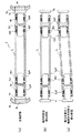
図4を参照して本実施形態4に係るガス絶縁母線について説明する。
図4(a)乃至(d)において、本実施形態4に係る導体2は、中央部が中空状に形成され、両端部に板状の接触片21a2、21b2を備えた中央部材21によって構成されている。そして、この板状の接触片21a2、21b2と対向する接触子5a、5bは、板状接触片21a2、21b2を両側から挟むように構成されたフィンガー状のスライドコンタクト導電部61a、61bを、ボルトによって一体的に固定し、コーン形絶縁スペーサ4a、4bの埋め込み電極4cに電気的に接続されかつ支持されている。
[Embodiment 4]
A gas-insulated bus according to the fourth embodiment will be described with reference to FIG.
4 (a) to 4 (d), the
以上のように構成された本実施形態4によれば、導体2は、両端部に軸方向および軸直角方向に摺動可能な板状接触子21a2、21b2を設けるとともに、この板状接触子21a2、21b2を挟むスライドコンタクト導電部61a、61bを設けたことにより、軸方向および軸直角方向の変位を吸収でき、常にスライドコンタクト導電部61a、61bの接触が保たれて通電性能を満足し、大変位した状態でも導体表面は連続的な面で構成されているため、絶縁性能は低下しない。
According to the fourth embodiment configured as described above, the
[実施形態5]
図5を参照して本実施形態5に係るガス絶縁母線について説明する。
図5(a)乃至(c)において、本実施形態5に係る導体2は、構成部品を大別すると、中空状の中央部材21と、その両端に接続される端部接続部材26a、26bとから構成される。
[Embodiment 5]
A gas-insulated bus according to the fifth embodiment will be described with reference to FIG.
In FIGS. 5 (a) to (c),
端部接続部材26a、26bは、一端部をロッド状の接触片26a1、26b1とし、他端部をパイプ状の接触片26a2、26b2として形成され、ロッド状の接触片26a1、26b1はスライドコンタクト導電部62a、62bを介して中央部材21の端部に対して軸方向および軸直角方向に摺動可能に嵌合されるようになっている。
End connection member 2 6 a, 2 6 b, one end portion of the contact piece 2 6 a1,2 6 b1 rod-shaped, is formed and the other end as a contact piece 2 6 a2,2 6 b2 pipe-shaped, rod-
そして、この端部接続部材26a、26bのパイプ状の接触片26a2、26b2は、コーン形絶縁スペーサ3a、3bの埋め込み電極4cに接続されたロッド状の接触子5a、5bをスライドコンタクト6a、6bを介して嵌入する。スライドコンタクト6a、6bも軸方向および軸直角方向に摺動可能になっている。
The contact piece 2 6 a2,2 6 b2 pipe-shaped of the end connection member 2 6 a, 2 6 b is cone-shaped insulating
この結果、中央部材21と端部接続部材26a、26bとはスライドコンタクト導電部62a、62bで電気的に接続され、また、端部接続部材4b、4cと接触子5a、5bは、スライドコンタクト導電部6a、6bで電気的に接続され、接触子5a、5bは、コーン形絶縁スペーサ4a、4bの埋め込み電極4cに接続される。
As a result, the central member 2 1 and the end
以上のように構成された本実施形態5によれば、導体2は、両端にそれぞれ2箇所のスライドコンタクト導電部6a、6bおよび62a、62bを設けたことで、軸直角方向の変位吸収量が2倍へ増やすことができ、また軸方向の変位はスライドコンタクト導電部で吸収でき、常にスライドコンタクト導電部の接触が保たれて通電性能を満足し、大変位した状態でも導体表面は連続的な面で構成されているため、絶縁性能は低下しない。片側に2箇所以上の複数個でも同様な効果が得られる。
According to the fifth embodiment configured as described above, the
[実施形態6]
図6を参照して本実施形態6に係るガス絶縁母線について説明する。
図6(a)乃至(c)において、本実施形態6に係る導体2は、中空状に形成されている。この中空状の導体2の両端部は、コイル径が大きいコイルバネ状接続部12a、12bを介してコーン形絶縁スペーサ4a、4bの埋め込み電極4cに接続されたロッド状の接触子5a、5bを嵌合するようになっている。
[Embodiment 6]
A gas-insulated bus according to the sixth embodiment will be described with reference to FIG.
6A to 6C, the
この結果、導体2は、両端内周部に軸方向および軸直角方向の双方の変位を吸収可能なコイル径を有するコイルバネ状接続部12a、12bを設けたことで、導体2の内径と接触子5a、5bの外径間に大きなギャップを確保して、接触状態を保つことができる。
As a result, the
以上のように構成された本実施形態6によれば、導体2は、両端に軸方向および軸直角方向の双方の変位を吸収可能なコイル径を有するコイルバネ状接続部12a、12bを設けたことで、導体2の内径と接触子5a、5bの外径間に大きなギャップを確保して、接触状態を保つことができる。このため、軸直角方向に変位した際、導体2の内径と接触子5a、5bの外径が接触しにくいので、大きな変位を吸収でき、軸直角方向および軸方向の大変位を吸収でき、常にコイルバネ状接続部の接触が保たれて通電性能を満足し、大変位した状態でも導体表面は連続的な面で構成されているため、絶縁性能は低下しない。
According to the sixth embodiment configured as described above, the
[実施形態7]
図7を参照して本実施形態7に係るガス絶縁母線について説明する。
図7において、本実施形態7の導体2は、構成部品を大別すると、中空状の中央部材21と、この中央部材21の両側に設けた軸直角方向の変位を吸収可能な蛇腹状導電部材13a、13bと、この蛇腹状導電部材13a、13bの更に外側に設けたパイプ形状の端部接続部材14a、14bとから構成されている。
パイプ形状の端部接続部材14a、14bは、スライドコンタクト導電部6a、6bを介して絶縁スペーサ4a、4bの埋め込み電極4cに接続されている。
[Embodiment 7]
A gas-insulated bus according to the seventh embodiment will be described with reference to FIG.
7, the
The pipe-shaped
このように、中央部材21は、蛇腹状導電部材13a、13b、パイプ形状の端部接続部材14a、14b、スライドコンタクト導電部6a、6bを介してロッド状接触子に接続される。
Thus, the central member 2 1, the bellows-like
以上のように構成された本実施形態7によれば、導体2は、両側に蛇腹状導電部材13a、13bを設けたことで、蛇腹状導電部材13a、13bの弾性変形により、導体2との軸直角方向への大変位吸収を可能とし、またスライドコンタクト導電部6a、6bを設け、導体2の軸方向への変位吸収も可能として、常にスライドコンタクト導電部6a、6bの接触が保たれて通電性能を満足し、大変位した状態でも導体表面は連続的な面で構成されているため、絶縁性能は低下しない。
According to the seventh embodiment configured as described above, the
[実施形態8]
図8を参照して本実施形態8に係るガス絶縁母線について説明する。
図8(a)乃至(c)において、本実施形態8に係る導体2は、中空状の中央部材21と、この中央部材21の両端部に接続され、軸直角方向の変位を吸収可能な中空の螺旋状導電部材15a、15bと、この螺旋状導電部材15a、15bの更に外側に接続されたパイプ形状の端部接続部材14a、14bとから構成される。
[Embodiment 8]
A gas insulated bus according to the eighth embodiment will be described with reference to FIG.
In FIG. 8 (a) to (c), the
そして、パイプ形状の端部接続部材14a、14bは、スライドコンタクト導電部6a、6bを介して絶縁スペーサ4a、4bの埋め込み電極4cに接続された接触子5a、5bに接続されるようになっている。
The pipe-shaped
この結果、中央部材21は、中空の螺旋状導電部材15a、15b、パイプ形状の端部接続部材14a、14b、スライドコンタクト導電部6a、6bを介して絶縁スペーサ4a、4bの埋め込み電極4cに接続される。
As a result, the central member 2 1 a hollow helical
以上のように構成された本実施形態8によれば、導体2は、両側に中空螺旋状部材15a、15bを設けたことで、その螺旋溝による導体の弾性変形で導体2との軸直角方向への大変位吸収を可能とし、またスライドコンタクト導電部6a、6bを設け、導体の軸方向への変位吸収も可能として、常にスライドコンタクト導電部6a、6bの接触が保たれて通電性能を満足し、大変位した状態でも導体表面は連続的な面で構成されているため、絶縁性能は低下しない。
According to the eighth embodiment configured as described above, the
[変形例]
以上の実施形態1乃至8では、導体2の例として中央部が中空状態の導体をとりあげたが、特に中空導体は必須ではなく、中実導体であっても差し支えない。
[Modification]
In Embodiments 1 to 8 described above, a conductor having a hollow central portion is taken up as an example of the
1…密閉容器、2…導体、21…中央部材、22a,22b…端部接続部材、23a,23b…ピン構造の連結接続部材、24a,24b…端部接続部材、25a,25b…中間接続部材、26a,26b…端部接続部材、3a,3b…伸縮継手、4a,4b…コーン形絶縁スペーサ、4c…埋め込み電極、5a,5b…接触子、61a,61b…板状両端接触子、6a,6b…スライドコンタクト導電部、7…絶縁ガス、8…回転止めピン、9a,9b…スライドコンタクト導電部、10…ボルト、11a,11b…ポスト形絶縁スペーサ、12a,12b…コイルバネ状接続部、13a,13b…蛇腹形状接続部材、14a,14b…パイプ状端部接続部材、15a,15b…螺旋形状接続部材。
DESCRIPTION OF SYMBOLS 1 ... Sealed container, 2 ... Conductor, 2 1 ... Center member, 2 2 a, 2 2 b ... End part connection member, 2 3 a, 2 3 b ... Pin connection connection member, 2 4 a, 2 4 b ... end connection member, 2 5 a, 2 5 b ... intermediate connection member, 2 6 a, 2 6 b ... end connection member, 3a, 3b ... expansion joint, 4a, 4b ... cone-shaped insulating spacer, 4c ... embedded Electrodes, 5a, 5b ... Contacts, 61a, 61b ... Plate-shaped both-end contacts, 6a, 6b ... Slide contact conductive part, 7 ... Insulating gas, 8 ... Rotation stop pin, 9a, 9b ... Slide contact conductive part, 10 ... Bolts, 11a, 11b ... post-shaped insulating spacers, 12a, 12b ... coil spring-like connection parts, 13a, 13b ... bellows-like connection members, 14a, 14b ... pipe-like end connection members, 15a, 15b ... spiral connection members.
Claims (7)
前記導体の両端部に、それぞれ導体の軸方向と直交する方向の変位を吸収することが可能な接続部と、導体の軸方向の変位を吸収することが可能な接続部とを備え、
前記導体の軸方向と直交する方向の変位を吸収することが可能な接続部を、ピン構造の回転摺動導電部で構成したことを特徴とするガス絶縁母線。 In a gas-insulated bus configured to house a conductor in an airtight container filled with insulating gas and to electrically connect the end of the conductor with a contact supported by an insulating spacer,
At both ends of the conductor, each comprises a connecting portion capable of absorbing displacement in a direction orthogonal to the axial direction of the conductor , and a connecting portion capable of absorbing displacement in the axial direction of the conductor ,
A gas-insulated bus characterized in that a connecting portion capable of absorbing displacement in a direction orthogonal to the axial direction of the conductor is constituted by a rotary sliding conductive portion having a pin structure .
前記導体の両端部に、それぞれ導体の軸方向と直交する方向の変位を吸収することが可能な接続部と、導体の軸方向の変位を吸収することが可能な接続部とを備え、
前記導体の軸方向と直交する方向の変位を吸収することが可能な接続部を、ピン構造の回転摺動導電部で構成し、
前記導体の軸方向の変位を吸収することが可能な接続部を、軸方向摺動用のスライドコンタクト導電部で構成したことを特徴とするガス絶縁母線。 In a gas-insulated bus configured to house a conductor in an airtight container filled with insulating gas and to electrically connect the end of the conductor with a contact supported by an insulating spacer,
At both ends of the conductor, each comprises a connecting portion capable of absorbing displacement in a direction orthogonal to the axial direction of the conductor , and a connecting portion capable of absorbing displacement in the axial direction of the conductor ,
The connecting portion capable of absorbing the displacement in the direction perpendicular to the axial direction of the conductor is constituted by a rotational sliding conductive portion having a pin structure,
A gas-insulated bus in which the connecting portion capable of absorbing the displacement in the axial direction of the conductor is constituted by a slide contact conductive portion for sliding in the axial direction .
前記導体の両側にそれぞれ板状接触子を設けると共に、この板状接触子を軸方向および軸直角方向に摺動可能に挟持するスライドコンタクト導電部を前記絶縁スペーサで支持された接触子に固定したことを特徴とするガス絶縁母線。 In a gas-insulated bus configured to house a conductor in an airtight container filled with insulating gas and to electrically connect the end of the conductor with a contact supported by an insulating spacer,
A plate contact is provided on each side of the conductor, and a slide contact conductive portion that slidably holds the plate contact in the axial direction and the direction perpendicular to the axis is fixed to the contact supported by the insulating spacer. A gas-insulated bus characterized by that.
Priority Applications (4)
| Application Number | Priority Date | Filing Date | Title |
|---|---|---|---|
| JP2010005010A JP5367593B2 (en) | 2010-01-13 | 2010-01-13 | Gas insulated bus |
| CN201180006058.1A CN102714403B (en) | 2010-01-13 | 2011-01-13 | Gas Insulated Busbar |
| BR112012017003A BR112012017003A2 (en) | 2010-01-13 | 2011-01-13 | gas insulated bus |
| PCT/JP2011/000127 WO2011086918A1 (en) | 2010-01-13 | 2011-01-13 | Gas insulating bus bar |
Applications Claiming Priority (1)
| Application Number | Priority Date | Filing Date | Title |
|---|---|---|---|
| JP2010005010A JP5367593B2 (en) | 2010-01-13 | 2010-01-13 | Gas insulated bus |
Publications (2)
| Publication Number | Publication Date |
|---|---|
| JP2011147242A JP2011147242A (en) | 2011-07-28 |
| JP5367593B2 true JP5367593B2 (en) | 2013-12-11 |
Family
ID=44304194
Family Applications (1)
| Application Number | Title | Priority Date | Filing Date |
|---|---|---|---|
| JP2010005010A Active JP5367593B2 (en) | 2010-01-13 | 2010-01-13 | Gas insulated bus |
Country Status (4)
| Country | Link |
|---|---|
| JP (1) | JP5367593B2 (en) |
| CN (1) | CN102714403B (en) |
| BR (1) | BR112012017003A2 (en) |
| WO (1) | WO2011086918A1 (en) |
Families Citing this family (7)
| Publication number | Priority date | Publication date | Assignee | Title |
|---|---|---|---|---|
| CN104776824A (en) * | 2014-12-11 | 2015-07-15 | 平高集团有限公司 | Monitoring method and monitoring device for radial displacement of GIL (gas insulated transmission line) |
| CN109755891B (en) * | 2019-01-30 | 2024-02-02 | 上海西门子高压开关有限公司 | Busbar components and gas-insulated metal-enclosed switchgear |
| CN110504652B (en) * | 2019-09-20 | 2020-11-24 | 国网河南省电力公司南阳供电公司 | A flexible fixing device for metal conductors of closed busbars of combined electrical appliances |
| CN111313164B (en) * | 2020-03-17 | 2021-05-14 | 广东电网有限责任公司 | An in-line busbar device |
| CN114974672B (en) * | 2022-06-24 | 2026-03-13 | 安徽埃克森科技集团有限公司 | A military-grade lightweight phase-stabilized cable |
| JP2024089372A (en) * | 2022-12-21 | 2024-07-03 | 株式会社オートネットワーク技術研究所 | Conductive member with terminal |
| JPWO2025041199A1 (en) * | 2023-08-18 | 2025-02-27 |
Family Cites Families (15)
| Publication number | Priority date | Publication date | Assignee | Title |
|---|---|---|---|---|
| CH548657A (en) * | 1972-08-23 | 1974-04-30 | Bbc Brown Boveri & Cie | HIGH VOLTAGE ELECTRIC CABLE WITH STRAIGHT PIECES. |
| CH566629A5 (en) * | 1973-11-28 | 1975-09-15 | Bbc Brown Boveri & Cie | |
| US3842187A (en) * | 1973-11-28 | 1974-10-15 | Gen Electric | Electric bus with joint for accommodating earthquake-produced motion of parts |
| JPS52100186U (en) * | 1976-01-28 | 1977-07-29 | ||
| JPS60117574U (en) * | 1984-01-18 | 1985-08-08 | 古河電気工業株式会社 | Universal conductor connection |
| JPS61173616A (en) * | 1985-01-25 | 1986-08-05 | 住友電気工業株式会社 | Pipeline air power transmission system |
| JPS63630U (en) * | 1986-06-16 | 1988-01-06 | ||
| SU1520618A1 (en) * | 1987-11-27 | 1989-11-07 | Центральное Проектно-Конструкторское Бюро Треста "Электромонтажконструкция" | Shaped section of bus circuit |
| JPH063630U (en) * | 1992-06-19 | 1994-01-18 | 東洋化学株式会社 | Decorative panel |
| JP3390762B2 (en) * | 1995-07-28 | 2003-03-31 | シャープ株式会社 | Matched filter circuit |
| JPH10248147A (en) * | 1997-02-28 | 1998-09-14 | Toshiba Corp | Expansion joint busbar and gas-insulated busbar using it |
| FR2844105B1 (en) * | 2002-08-27 | 2006-11-17 | Framatome Connectors Int | CONNECTION DEVICE HAVING A SURROUNDED SPRING CONTACT |
| DE10359820A1 (en) * | 2003-12-19 | 2005-07-21 | Siemens Ag | Device for fixing a magnetic rail of an electric linear motor to a carrier |
| JP2008263707A (en) * | 2007-04-11 | 2008-10-30 | Toshiba Corp | Gas insulated expansion joint for gas insulated bus |
| JP5075617B2 (en) * | 2007-12-27 | 2012-11-21 | 株式会社東芝 | Gas insulated bus conductor |
-
2010
- 2010-01-13 JP JP2010005010A patent/JP5367593B2/en active Active
-
2011
- 2011-01-13 WO PCT/JP2011/000127 patent/WO2011086918A1/en not_active Ceased
- 2011-01-13 CN CN201180006058.1A patent/CN102714403B/en active Active
- 2011-01-13 BR BR112012017003A patent/BR112012017003A2/en not_active IP Right Cessation
Also Published As
| Publication number | Publication date |
|---|---|
| BR112012017003A2 (en) | 2019-09-24 |
| CN102714403A (en) | 2012-10-03 |
| CN102714403B (en) | 2015-06-17 |
| JP2011147242A (en) | 2011-07-28 |
| WO2011086918A1 (en) | 2011-07-21 |
Similar Documents
| Publication | Publication Date | Title |
|---|---|---|
| JP5367593B2 (en) | Gas insulated bus | |
| US8748757B2 (en) | Temperature compensated bushing design | |
| US20100200275A1 (en) | Gas insulated transmission line having improved performance of electric contact at connection parts of the conductors | |
| KR20040111104A (en) | Termination structure of cryogenic cable | |
| CN201393015Y (en) | Support structure for three-phase conducting pole | |
| JP2014030282A (en) | Three-phase gas-insulated bus | |
| JP4177628B2 (en) | Compound insulation type gas insulated switchgear | |
| US4316052A (en) | Gas insulated transmission line having two-legged spacers disposed in a receiving structure | |
| KR101654949B1 (en) | Surge arrestor arrangement comprising an arrestor current path with a plurality of arrestor columns | |
| CN1996688A (en) | Insulator arrangement | |
| CN102823095B (en) | Gas insulated bus | |
| CN101641833B (en) | A high current connector | |
| CN204578028U (en) | A kind of two universal compensation bus unit of expansion joint pressure-balancing type | |
| JP4922012B2 (en) | conductor | |
| JP2020510955A (en) | High power bushings for harsh environments | |
| JP6689161B2 (en) | Gas insulated switchgear | |
| US5401923A (en) | Resistor-provided UHV breaker | |
| JP5159954B2 (en) | Gas insulated bus | |
| JPS5838758Y2 (en) | gas insulated equipment | |
| JP3233460B2 (en) | Circuit breaker with resistance | |
| JPH11122730A (en) | Gas insulated switch device | |
| Pahl et al. | Design of a cylindrical high-voltage high-temperature vacuum insulator | |
| KR19990073139A (en) | Busbar connecting mechanism of gas insulating switch | |
| JP2000059960A (en) | Gas insulated busbar | |
| JPS5879417A (en) | Gas insulated bus |
Legal Events
| Date | Code | Title | Description |
|---|---|---|---|
| A621 | Written request for application examination |
Free format text: JAPANESE INTERMEDIATE CODE: A621 Effective date: 20120821 |
|
| A131 | Notification of reasons for refusal |
Free format text: JAPANESE INTERMEDIATE CODE: A131 Effective date: 20130604 |
|
| A521 | Written amendment |
Free format text: JAPANESE INTERMEDIATE CODE: A523 Effective date: 20130731 |
|
| TRDD | Decision of grant or rejection written | ||
| A01 | Written decision to grant a patent or to grant a registration (utility model) |
Free format text: JAPANESE INTERMEDIATE CODE: A01 Effective date: 20130820 |
|
| A61 | First payment of annual fees (during grant procedure) |
Free format text: JAPANESE INTERMEDIATE CODE: A61 Effective date: 20130911 |
|
| R151 | Written notification of patent or utility model registration |
Ref document number: 5367593 Country of ref document: JP Free format text: JAPANESE INTERMEDIATE CODE: R151 |