JP5367564B2 - Tendon repair assembly, tendon engagement member and bone penetration assembly - Google Patents
Tendon repair assembly, tendon engagement member and bone penetration assembly Download PDFInfo
- Publication number
- JP5367564B2 JP5367564B2 JP2009505958A JP2009505958A JP5367564B2 JP 5367564 B2 JP5367564 B2 JP 5367564B2 JP 2009505958 A JP2009505958 A JP 2009505958A JP 2009505958 A JP2009505958 A JP 2009505958A JP 5367564 B2 JP5367564 B2 JP 5367564B2
- Authority
- JP
- Japan
- Prior art keywords
- tendon
- bone
- suture
- repair assembly
- engagement
- Prior art date
- Legal status (The legal status is an assumption and is not a legal conclusion. Google has not performed a legal analysis and makes no representation as to the accuracy of the status listed.)
- Expired - Fee Related
Links
- 0 *C1C(C2)CC2C1 Chemical compound *C1C(C2)CC2C1 0.000 description 1
Images


Classifications
-
- A—HUMAN NECESSITIES
- A61—MEDICAL OR VETERINARY SCIENCE; HYGIENE
- A61F—FILTERS IMPLANTABLE INTO BLOOD VESSELS; PROSTHESES; DEVICES PROVIDING PATENCY TO, OR PREVENTING COLLAPSING OF, TUBULAR STRUCTURES OF THE BODY, e.g. STENTS; ORTHOPAEDIC, NURSING OR CONTRACEPTIVE DEVICES; FOMENTATION; TREATMENT OR PROTECTION OF EYES OR EARS; BANDAGES, DRESSINGS OR ABSORBENT PADS; FIRST-AID KITS
- A61F2/00—Filters implantable into blood vessels; Prostheses, i.e. artificial substitutes or replacements for parts of the body; Appliances for connecting them with the body; Devices providing patency to, or preventing collapsing of, tubular structures of the body, e.g. stents
- A61F2/02—Prostheses implantable into the body
- A61F2/08—Muscles; Tendons; Ligaments
- A61F2/0811—Fixation devices for tendons or ligaments
-
- A—HUMAN NECESSITIES
- A61—MEDICAL OR VETERINARY SCIENCE; HYGIENE
- A61B—DIAGNOSIS; SURGERY; IDENTIFICATION
- A61B17/00—Surgical instruments, devices or methods
- A61B17/04—Surgical instruments, devices or methods for suturing wounds; Holders or packages for needles or suture materials
- A61B17/0469—Suturing instruments for use in minimally invasive surgery, e.g. endoscopic surgery
-
- A—HUMAN NECESSITIES
- A61—MEDICAL OR VETERINARY SCIENCE; HYGIENE
- A61B—DIAGNOSIS; SURGERY; IDENTIFICATION
- A61B17/00—Surgical instruments, devices or methods
- A61B17/04—Surgical instruments, devices or methods for suturing wounds; Holders or packages for needles or suture materials
- A61B17/06—Needles ; Sutures; Needle-suture combinations; Holders or packages for needles or suture materials
- A61B17/062—Needle manipulators
- A61B17/0625—Needle manipulators the needle being specially adapted to interact with the manipulator, e.g. being ridged to snap fit in a hole of the manipulator
-
- A—HUMAN NECESSITIES
- A61—MEDICAL OR VETERINARY SCIENCE; HYGIENE
- A61B—DIAGNOSIS; SURGERY; IDENTIFICATION
- A61B17/00—Surgical instruments, devices or methods
- A61B17/16—Instruments for performing osteoclasis; Drills or chisels for bones; Trepans
- A61B17/1642—Instruments for performing osteoclasis; Drills or chisels for bones; Trepans for producing a curved bore
-
- A—HUMAN NECESSITIES
- A61—MEDICAL OR VETERINARY SCIENCE; HYGIENE
- A61B—DIAGNOSIS; SURGERY; IDENTIFICATION
- A61B17/00—Surgical instruments, devices or methods
- A61B17/16—Instruments for performing osteoclasis; Drills or chisels for bones; Trepans
- A61B17/17—Guides or aligning means for drills, mills, pins or wires
- A61B17/1739—Guides or aligning means for drills, mills, pins or wires specially adapted for particular parts of the body
- A61B17/1778—Guides or aligning means for drills, mills, pins or wires specially adapted for particular parts of the body for the shoulder
-
- A—HUMAN NECESSITIES
- A61—MEDICAL OR VETERINARY SCIENCE; HYGIENE
- A61F—FILTERS IMPLANTABLE INTO BLOOD VESSELS; PROSTHESES; DEVICES PROVIDING PATENCY TO, OR PREVENTING COLLAPSING OF, TUBULAR STRUCTURES OF THE BODY, e.g. STENTS; ORTHOPAEDIC, NURSING OR CONTRACEPTIVE DEVICES; FOMENTATION; TREATMENT OR PROTECTION OF EYES OR EARS; BANDAGES, DRESSINGS OR ABSORBENT PADS; FIRST-AID KITS
- A61F2/00—Filters implantable into blood vessels; Prostheses, i.e. artificial substitutes or replacements for parts of the body; Appliances for connecting them with the body; Devices providing patency to, or preventing collapsing of, tubular structures of the body, e.g. stents
- A61F2/02—Prostheses implantable into the body
- A61F2/08—Muscles; Tendons; Ligaments
- A61F2/0805—Implements for inserting tendons or ligaments
-
- A—HUMAN NECESSITIES
- A61—MEDICAL OR VETERINARY SCIENCE; HYGIENE
- A61B—DIAGNOSIS; SURGERY; IDENTIFICATION
- A61B17/00—Surgical instruments, devices or methods
- A61B17/04—Surgical instruments, devices or methods for suturing wounds; Holders or packages for needles or suture materials
- A61B17/0482—Needle or suture guides
-
- A—HUMAN NECESSITIES
- A61—MEDICAL OR VETERINARY SCIENCE; HYGIENE
- A61B—DIAGNOSIS; SURGERY; IDENTIFICATION
- A61B17/00—Surgical instruments, devices or methods
- A61B17/04—Surgical instruments, devices or methods for suturing wounds; Holders or packages for needles or suture materials
- A61B17/0487—Suture clamps, clips or locks, e.g. for replacing suture knots; Instruments for applying or removing suture clamps, clips or locks
-
- A—HUMAN NECESSITIES
- A61—MEDICAL OR VETERINARY SCIENCE; HYGIENE
- A61B—DIAGNOSIS; SURGERY; IDENTIFICATION
- A61B17/00—Surgical instruments, devices or methods
- A61B17/16—Instruments for performing osteoclasis; Drills or chisels for bones; Trepans
- A61B17/1662—Instruments for performing osteoclasis; Drills or chisels for bones; Trepans for particular parts of the body
- A61B17/1684—Instruments for performing osteoclasis; Drills or chisels for bones; Trepans for particular parts of the body for the shoulder
-
- A—HUMAN NECESSITIES
- A61—MEDICAL OR VETERINARY SCIENCE; HYGIENE
- A61B—DIAGNOSIS; SURGERY; IDENTIFICATION
- A61B17/00—Surgical instruments, devices or methods
- A61B17/04—Surgical instruments, devices or methods for suturing wounds; Holders or packages for needles or suture materials
- A61B17/0401—Suture anchors, buttons or pledgets, i.e. means for attaching sutures to bone, cartilage or soft tissue; Instruments for applying or removing suture anchors
- A61B2017/0417—T-fasteners
-
- A—HUMAN NECESSITIES
- A61—MEDICAL OR VETERINARY SCIENCE; HYGIENE
- A61B—DIAGNOSIS; SURGERY; IDENTIFICATION
- A61B17/00—Surgical instruments, devices or methods
- A61B17/04—Surgical instruments, devices or methods for suturing wounds; Holders or packages for needles or suture materials
- A61B17/0401—Suture anchors, buttons or pledgets, i.e. means for attaching sutures to bone, cartilage or soft tissue; Instruments for applying or removing suture anchors
- A61B2017/0446—Means for attaching and blocking the suture in the suture anchor
- A61B2017/0454—Means for attaching and blocking the suture in the suture anchor the anchor being crimped or clamped on the suture
-
- A—HUMAN NECESSITIES
- A61—MEDICAL OR VETERINARY SCIENCE; HYGIENE
- A61B—DIAGNOSIS; SURGERY; IDENTIFICATION
- A61B17/00—Surgical instruments, devices or methods
- A61B17/04—Surgical instruments, devices or methods for suturing wounds; Holders or packages for needles or suture materials
- A61B17/0469—Suturing instruments for use in minimally invasive surgery, e.g. endoscopic surgery
- A61B2017/0472—Multiple-needled, e.g. double-needled, instruments
-
- A—HUMAN NECESSITIES
- A61—MEDICAL OR VETERINARY SCIENCE; HYGIENE
- A61B—DIAGNOSIS; SURGERY; IDENTIFICATION
- A61B17/00—Surgical instruments, devices or methods
- A61B17/04—Surgical instruments, devices or methods for suturing wounds; Holders or packages for needles or suture materials
- A61B2017/0496—Surgical instruments, devices or methods for suturing wounds; Holders or packages for needles or suture materials for tensioning sutures
-
- A—HUMAN NECESSITIES
- A61—MEDICAL OR VETERINARY SCIENCE; HYGIENE
- A61B—DIAGNOSIS; SURGERY; IDENTIFICATION
- A61B17/00—Surgical instruments, devices or methods
- A61B17/04—Surgical instruments, devices or methods for suturing wounds; Holders or packages for needles or suture materials
- A61B17/06—Needles ; Sutures; Needle-suture combinations; Holders or packages for needles or suture materials
- A61B17/06004—Means for attaching suture to needle
- A61B2017/06042—Means for attaching suture to needle located close to needle tip
-
- A—HUMAN NECESSITIES
- A61—MEDICAL OR VETERINARY SCIENCE; HYGIENE
- A61B—DIAGNOSIS; SURGERY; IDENTIFICATION
- A61B17/00—Surgical instruments, devices or methods
- A61B17/04—Surgical instruments, devices or methods for suturing wounds; Holders or packages for needles or suture materials
- A61B17/06—Needles ; Sutures; Needle-suture combinations; Holders or packages for needles or suture materials
- A61B2017/06057—Double-armed sutures, i.e. sutures having a needle attached to each end
Landscapes
- Health & Medical Sciences (AREA)
- Life Sciences & Earth Sciences (AREA)
- Surgery (AREA)
- Veterinary Medicine (AREA)
- Biomedical Technology (AREA)
- Heart & Thoracic Surgery (AREA)
- Animal Behavior & Ethology (AREA)
- General Health & Medical Sciences (AREA)
- Public Health (AREA)
- Engineering & Computer Science (AREA)
- Medical Informatics (AREA)
- Molecular Biology (AREA)
- Nuclear Medicine, Radiotherapy & Molecular Imaging (AREA)
- Oral & Maxillofacial Surgery (AREA)
- Orthopedic Medicine & Surgery (AREA)
- Dentistry (AREA)
- Rehabilitation Therapy (AREA)
- Cardiology (AREA)
- Transplantation (AREA)
- Vascular Medicine (AREA)
- Rheumatology (AREA)
- Surgical Instruments (AREA)
- Prostheses (AREA)
- Materials For Photolithography (AREA)
- Springs (AREA)
- Control Of Throttle Valves Provided In The Intake System Or In The Exhaust System (AREA)
Abstract
Description
本発明は、損傷した腱を修復するためのアッセンブリに関し、特に、限定されないが、損傷した回旋腱板の関節鏡視下の修復のためのアッセンブリに関する。また、本発明は、上記アッセンブリに用いられる腱係合部材および骨貫通アッセンブリに関する。 The present invention relates to an assembly for repairing a damaged tendon, and more particularly, but not exclusively, to an assembly for arthroscopic repair of a damaged rotator cuff. The present invention also relates to a tendon engaging member and a bone penetrating assembly used in the assembly.
回旋腱板、すなわち肩の関節を包み込んで肩甲骨に上腕を付着させる4つの筋の群は、一つには、体の他の関節よりも広い範囲にわたって肩を運動及び回転させ得るため、我々は日常的な作業を行うよう手を位置させることができる。不都合なことに、回旋腱板の損傷は、多くの日常の活動を困難且つ苦痛なものにさせるが;迅速な診断及び治療によりこれらの症状を著しく改善させる可能性がある。このような損傷は、多くのメカニズムに起因するものである:アーチ状の肩甲骨に対する機械的な摩擦により腱の中に断裂といった欠陥を形成する、又は広げた腕を突いた場合のような外傷により腱板がその骨の付着部から引き離される可能性がある。このような損傷の治療は、損傷への血液の供給の減少によって複雑化する可能性がある。 Because the rotator cuff, the group of four muscles that wrap around the shoulder joint and attach the upper arm to the scapula, can move and rotate the shoulder over a wider range than other joints in the body, Can position their hands to do everyday tasks. Unfortunately, rotator cuff injury makes many everyday activities difficult and painful; rapid diagnosis and treatment can significantly improve these symptoms. Such damage is due to a number of mechanisms: trauma such as rupture in the tendon due to mechanical friction against the arched scapula or striking an extended arm. Can cause the rotator cuff to be pulled away from the bone attachment. Treatment of such injuries can be complicated by a decrease in blood supply to the injuries.
回旋腱板の損傷は、先進国全体の肩の診療科における症状の約1/3を占めており、大部分は高齢者、しかしながら若年者にも見られる。若い患者は、多くの場合、外傷につながる事故に遭っていたり、又はプロのスポーツ選手に見られるように肩を酷使している。年齢とともに、回旋腱板の組織が弾力性を失ってきて損傷をより起こし易くなり、多くの場合日常の活動を行う間に損傷を受ける。しかしながら、治療しなかったり又は治療が失敗した場合、長期にわたる回旋腱板の損傷により肩の関節の変性につながり、場合によっては関節の交換を要する。 Injuries to the rotator cuff account for about one third of the symptoms in the shoulder departments of developed countries as a whole, and most are found in older people, but also in younger people. Young patients often have accidents that lead to trauma, or overuse their shoulders as seen by professional athletes. With age, the rotator cuff tissue loses its elasticity and becomes more susceptible to damage and is often damaged during daily activities. However, if treatment is unsuccessful or treatment fails, prolonged rotation of the rotator cuff can lead to degeneration of the shoulder joint, sometimes requiring joint replacement.
回旋腱板の損傷は、限られた効果しかない身体のリハビリテーションにより治療されるが、筋の群の機能を矯正するのに外科手術が必要である。回旋腱板の修復手術は、従来の大きな6−10cmの切開、3−5cmの切開のいずれかによって、又は「関節鏡手術」と称される3箇所から4箇所の1cm小さな切開とキーホールカメラ及び器具を使用して行うことができる。大きな外科的な切開は著しい痛みをもたらし、多くの場合、回旋腱板が治癒した後でさえもいつまでも続く問題を生じる。このため、損傷を修復するのに使用する傷の大きさを小さくすると、術後の痛みが減り、回復期間を短くすることができ、これによりこのような状態を管理するためのコストを減らす。 Injuries to the rotator cuff are treated by physical rehabilitation with limited effects, but surgery is required to correct the function of the muscle group. The rotator cuff repair can be done with either a conventional large 6-10 cm incision, a 3-5 cm incision, or three to four 1 cm small incisions and keyhole cameras referred to as “arthroscopic surgery” And using instruments. Large surgical incisions can cause significant pain and often cause problems that persist indefinitely even after the rotator cuff has healed. Thus, reducing the size of the wound used to repair the injury can reduce post-operative pain and shorten the recovery period, thereby reducing the cost of managing such conditions.
損傷した回旋腱板を再び付着させる目的は、3つの方法全てを使用するのと同じであるが、用いる切開の大きさが小さくなることで必要とされる外科手術のスキルのレベルを高くする。結果として、既知の方法を使用して関節鏡視下で行われる修復の質は、観血的な回旋腱板の修復箇所と同じ強度及び整合性を有しない可能性がある。 The purpose of reattaching the damaged rotator cuff is the same as using all three methods, but increases the level of surgical skill required by reducing the size of the incision used. As a result, the quality of repair performed arthroscopically using known methods may not have the same strength and consistency as the repair site of an open rotator cuff.
関節鏡視下の手術をより簡単にするために、腱の表面に施される結節縫合を要する定着システムが開発されている。しかしながら、これらの結節縫合自身は、腱の上の骨によって摩耗する(「衝突摩耗」と称される)ことが分かっており、修復を乱してさらには回旋腱板を刺激及び損傷する。 In order to make arthroscopic surgery easier, anchoring systems have been developed that require knot sutures applied to the surface of the tendon. However, these knot sutures themselves have been found to be worn by the bone above the tendon (referred to as “impact wear”), disturbing the repair and even stimulating and damaging the rotator cuff.
従来の関節鏡視下の回旋腱板修復(ARCR)は、同じレベルの手術のスキルに関して、対応する観血的な修復よりも手術時間が長くなり失敗率が高くなる技術的に困難な手術である。さらに、使用する器具は高価で多くの場合手術は労働集約的である(主要な外科医及び補助の外科医を要する)。しかしながら、ARCRの利点は、これらの潜在的な問題をしばしば過小評価する;手術中の罹患率の減少及び関連する入院期間の長さにより大量の患者を引き受けることになる。実際には、外来を原則として手術が行われる可能性がある。ARCRの成功に最重要なことは、熟練した関節鏡視下の外科医による手術の計画及び処置へのシステマチックで段階的な取り組みである。 Traditional arthroscopic rotator cuff repair (ARCR) is a technically difficult operation with a longer surgical time and higher failure rate than the corresponding open repair for the same level of surgical skills. is there. Furthermore, the instruments used are expensive and often the operation is labor intensive (requires a main surgeon and an auxiliary surgeon). However, the benefits of ARCR often underestimate these potential problems; undertaking a large number of patients due to reduced morbidity during surgery and associated length of hospital stay. In practice, surgery may be performed on an outpatient basis. Most important to the success of the ARCR is a systematic and step-by-step approach to surgical planning and treatment by a skilled arthroscopic surgeon.
米国特許第6,206,886号及び米国特許第6,013,083号は、カニューレ及びドリルガイドさらには別個の外部からの組織把持具を使用して、挿入部位に腱を縮小させて戻すことを記載している。これは、単に関節鏡視下の方法としてその使用を妨げる。また、米国特許第6,206,886号は、別個の組織把持具及び固定器具を要するが、これは同時に使用される少なくとも2箇所の別個の関節鏡用のポータルを要し、外科手術の複雑さを増している。 US Pat. No. 6,206,886 and US Pat. No. 6,013,083 use a cannula and drill guide or even a separate external tissue grasper to reduce the tendon back to the insertion site. Is described. This precludes its use as an arthroscopic method. US Pat. No. 6,206,886 also requires a separate tissue grasper and fixation device, which requires at least two separate arthroscopic portals to be used at the same time, complicating the surgical procedure. It is increasing.
米国特許番号第6,491,714号は、回旋腱板を固定及び再付着させるための器具を記載しているが、解決法は何も低減しない別個の組織把持具及び縫合糸取付具を含んでいる。米国特許番号第5,681,333号(縫合糸の取り付けのための骨の通路を使用した関節鏡視下の回旋腱板の修復のための方法及び器具)は、固定を行う間に縮小位置に回旋腱板を保持するのに使用する別個の「牽引縫合糸」を要する関節鏡器具を記載している。 US Pat. No. 6,491,714 describes an instrument for securing and reattaching a rotator cuff, but the solution includes a separate tissue grasper and suture attachment that does not reduce anything It is out. US Pat. No. 5,681,333 (method and instrument for arthroscopic rotator cuff repair using a bone passage for suture attachment) is in a reduced position during fixation Describes an arthroscopic instrument that requires a separate “traction suture” used to hold the rotator cuff.
米国特許番号第5,575,801号(関節鏡視下の回旋腱板の修復のための方法及び器具)では、固定の間に腱を縮小させ得る器具が提供されているが、この解決法は上腕の強い横方向の皮質骨の固定ができない。 US Pat. No. 5,575,801 (Method and Instrument for Arthroscopic Rotator Cuff Repair) provides an instrument that can reduce the tendon during fixation, but this solution Can not fix strong lateral cortical bone of the upper arm.
米国特許番号第2004/0193217号及びWO 2003/034895号は、関節鏡視下の腱又は靱帯の修復のための方法を提供しており、腱及び/又は骨の固定具の組み合わせの使用を含んでいる。また、関節鏡視下の手術で使用する組織把持具、(例えば、米国特許番号第2005/0085850号)及び骨への結合組織の取り付けのための縫合糸固定具(例えば、WO 2002/065892号)が、当技術分野で既知である。 US Patent No. 2004/0193217 and WO 2003/034895 provide methods for arthroscopic tendon or ligament repair, including the use of tendon and / or bone anchor combinations It is out. Also, tissue grippers for use in arthroscopic surgery (eg, US Patent No. 2005/0085850) and suture anchors for attachment of connective tissue to bone (eg, WO 2002/065892). ) Is known in the art.
本発明の態様は、独立請求項1,19,20及び35で提示されている。
Aspects of the invention are presented in the
さらに、追加的な態様がそれらに従属する残りの請求項で提示されている。 Furthermore, additional aspects are presented in the remaining claims dependent thereon.
(従来技術のように腱を引っ張るのではなく)腱の挿入部位に腱を押すことによって、関節の固定する側と同じ側に隙間の縮小が生じるため、修復に要する器具の数又は連続的なステップを減らす。都合のよいことに、回旋腱板の修復では、腱の挿入部位への損傷した腱の縮小と、これと同時に(骨に腱を押すことによる)回旋腱板の関節鏡視下での固定とを組み合わせることにより、回旋腱板の関節鏡視下での修復が促進される。修復部を腱の外側にある強い皮質骨に固定してもよいため、修復固定材料の衝突の可能性を最小限にして強固な固定を与える。複数の縫合糸の使用によって同じような強固な修復を実現する。 By pushing the tendon to the tendon insertion site (rather than pulling the tendon as in the prior art), the gap is reduced on the same side as the side where the joint is fixed. Reduce steps. Conveniently, rotator cuff repair involves shrinking the damaged tendon to the tendon insertion site and simultaneously fixing the rotator cuff (by pushing the tendon into the bone) under arthroscopy. By combining these, the arthroscopic repair of the rotator cuff is promoted. Since the repaired part may be fixed to the strong cortical bone outside the tendon, it provides a strong fixation with minimal possibility of collision of the repair fixing material. Use of multiple sutures achieves a similar robust repair.
ある実施例では、1つの関節視鏡用ポータル、例えば、Neviaserポータルといった上ポータルを通して修復が実施されるように、有利に全ての操作が肩の内側で実施される。 In certain embodiments, all operations are advantageously performed inside the shoulder so that the repair is performed through an upper portal, such as an arthroscopic portal, eg, a Neviaser portal.
他の実施例では、腱の隙間縮小及び固定が肩の内側で実施される一方で、修復部が肩の外側で固定され、修復アッセンブリを構成する点で有利により大きな柔軟性が可能である。有利に、アッセンブリを肩の外側で全体的に動かしてもよいため、患者の肩と頭部との間の制限された空間内で動かさなければならないことはない。ある特定の実施例では、修復部が上腕骨の大結節を通してアーチ形の軌道で縫合されることで、縫合糸を保持する骨の質量を増す。この実施例はさらに、修復アッセンブリの移動パーツのアーチ形の軌道を規定することによって、腱及び対向する上腕骨の外側皮質への修復アッセンブリの有利な接近角度及び関係のある関節視鏡用ポータルを通した良好な接近が可能となる。 In another embodiment, tendon clearance reduction and fixation is performed inside the shoulder, while the repair is fixed outside the shoulder, advantageously allowing greater flexibility in constructing the repair assembly. Advantageously, the assembly may be moved globally outside the shoulder so that it does not have to be moved within a limited space between the patient's shoulder and head. In one particular embodiment, the repair is sutured through an arched trajectory through the humerus nodule to increase the mass of the bone holding the suture. This embodiment further provides an advantageous approach angle and associated arthroscopic portal of the repair assembly to the external cortex of the tendon and the opposing humerus by defining an arcuate trajectory of the moving part of the repair assembly. Good access through is possible.
ここで、添付図面を参照して単なる一例として本発明の実施例を説明する。特許請求の範囲に記載の発明は主に図18A、図19に示す実施例に対応しており、例えば図1に示す他の実施例は発明の理解の補助となる参考例として記載されている。
Embodiments of the present invention will now be described by way of example only with reference to the accompanying drawings. The invention described in the claims mainly corresponds to the embodiment shown in FIGS. 18A and 19. For example, the other embodiment shown in FIG. 1 is described as a reference example for assisting the understanding of the invention. .
回旋腱板を修復するための本実施例の器具を、「ビーチチェア」(座位)又は「側位」(横臥位)の位置のいずれかで使用できるが、前者の位置は本器具の最適な位置決め及び処置の間の動作アームの操作が可能となり、これら双方が処置の成功を助ける。処置全体にわたって肩を操作するが、「ビーチチェア」位置にあるとともに制御位置では肘が横にあり、前腕が患者の胴体に載せられる。 The device of this embodiment for repairing the rotator cuff can be used in either the “beach chair” (sitting position) or “side” (recumbent position) position, but the former position is optimal for the device. Operation of the motion arm during positioning and treatment is possible, both of which help the treatment succeed. Manipulate the shoulder throughout the procedure, but in the “beach chair” position and in the control position the elbow is on the side and the forearm rests on the patient's torso.
肩の後部(後ポータル)、側部(横ポータル)、前部(前ポータル)及び上部(例えば、Neviaserといった上ポータル)に小さな(5−10mm)ポータル切開が形成され、関節及び腱板の損傷を視覚化して器具の使用が可能となる。最適な実施として、関節鏡検査による徹底した診断(肩の関節の検査)及び滑液包の診断(滑液包の検査)が始めに実施される。肩の中の二頭筋腱、頭部及び関節窩の軟骨表面、受動的に安定化させる生体構造、回旋腱板を検査するために注意が向けられ、徹底した検査の後に病状に取り組む。 Small (5-10 mm) portal incisions are made in the back (back portal), side (lateral portal), front (front portal) and top (eg, upper portals such as Neviaser) of the shoulder, resulting in joint and rotator cuff damage It is possible to use the instrument by visualizing As an optimal implementation, a thorough diagnosis by arthroscopy (shoulder joint examination) and a bursa diagnosis (synovial bursa examination) are performed first. Attention is directed to examining the biceps tendon in the shoulder, the cartilage surface of the head and glenoid, passively stabilizing anatomy, and the rotator cuff, and the condition is addressed after a thorough examination.
視覚化すると、関節及び腱板を修復のために準備する必要がある。肩峰の手術前の評価及び手術中の評価は、肩峰形成術についての指針となる;英国における回旋腱板の修復でよく行われているように、目的は、肩峰の下面を滑らか且つ平らにして、修復のためのより大きい空間を与え、圧力を治療する腱から解放することである。 Once visualized, the joints and rotator cuff need to be prepared for repair. Preoperative and intraoperative assessment of the acromia is a guide for acromioplasty; as is often done in rotator cuff repair in the UK, the goal is to ensure that the lower surface of the acromia is smooth and Flatten to give more space for repair and release pressure from the tendon to treat.
そして、最も適切なポータルを介して回旋腱板の損傷を視覚化する。損傷の大きさ及びパターンが評価される。薄い部分又は断裂した部分が取り除かれ、腱が骨に再び取り付けられる領域が積極的に(又は場合により軽く)切除され、回復のために新たな血管の成長を促す。このような切除は掘削器具又はドリルを用いた関節鏡視下手術であり、元来の上腕骨の付着部において全ての軟骨及び皮質骨を取り除くのに効果的である。 Visualize the rotator cuff injury through the most appropriate portal. Damage magnitude and pattern are evaluated. The thin or torn portion is removed and the area where the tendon is reattached to the bone is actively (or even lightly) resected to encourage the growth of new blood vessels for recovery. Such excision is an arthroscopic surgery using a drilling instrument or drill and is effective in removing all cartilage and cortical bone at the original humeral attachment.
本器具の実施例を用いた修復処置が、本器具の構造の詳細な記載とともに、以下にさらに詳細に説明されている。手短に言えば、押す力を加えることによって腱がその挿入部位に下げられ、縫合糸が上ポータルから腱及び上腕頭を通り抜け、又は縫合糸が横ポータルの内側から外側に取り出される。 Repair procedures using embodiments of the instrument are described in further detail below, along with a detailed description of the structure of the instrument. Briefly, by applying a pushing force, the tendon is lowered to its insertion site and the suture passes from the upper portal through the tendon and humeral head, or the suture is removed from the inside to the outside of the lateral portal.
手術が完了すると、肩に長時間作用型の局所麻酔薬が注射され、疼痛処理がし易くなる。各ポータルの切開が(切開の大きさに応じて)1又はそれ以上の縫い目で閉じられ、「滅菌した帯状の」テープで覆い、続いて乾燥した滅菌包帯で覆う。また、圧迫包帯を用いて術後の出血及び動き易さを減らす。最後に、肩の吊り包帯又はギプスが固定化及び部位の保護のために適用される。固定する場所は、例えば30の外転ウェッジを用いて30度外転及び中立回転した位置である。 When the operation is completed, a long-acting local anesthetic is injected into the shoulder, facilitating pain treatment. The incision in each portal is closed with one or more seams (depending on the size of the incision), covered with “sterile band” tape, followed by a dry sterile bandage. It also uses a compression bandage to reduce postoperative bleeding and ease of movement. Finally, a shoulder bandage or cast is applied for immobilization and site protection. The place to be fixed is, for example, a position rotated 30 degrees and neutrally rotated using 30 abduction wedges.
術後のケアは器具に特有ではないが、利用可能な便利さ及び特定の場所の管理指針次第である。一般に、患者は指示される。一般に患者は、外側に向けた軸回転における軽い屈伸−伸長の振子運動で始まる、術後の1日2日の軽い範囲の運動を指示される(回復段階I)。術後2日後に、圧迫包帯を取り除くことができ、肘を脇から離す活発な運動は抑えなければならないが、肘を脇に保持しながら動かせる側の手の使用が奨められる。術後4−8週で、患者は痛みの無い活発な運動に移ることできるが(回復段階II)、術後10−12週は抵抗運動を控えるべきである。
Post-surgical care is not specific to the device, but depends on the convenience available and the specific site management guidelines. In general, the patient is instructed. Generally, the patient is instructed with a light range of
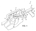
図1を参照すると、修復器具の実施例が、主要な部品がフックガイド4及びフックガイド4によって案内される間隔縮小部6であるアッセンブリを有している。 Referring to FIG. 1, an embodiment of a repair device has an assembly in which the main parts are a hook guide 4 and a space reduction portion 6 guided by the hook guide 4.
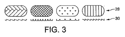
フックガイド4は、骨係合フック8と、曲がったネック部10によってフック8に結合された案内部12とを有している。案内部12は、間隔縮小部6の円筒形の細長部16を受容するよう構成された円筒状の案内通路14を規定する。ハンドル20が間隔縮小部6の第1の端部18で延びている。間隔縮小部の第2の端部22、すなわち間隔縮小部6の端面は、間隔縮小部6の長手軸24に対して角度を成しており、腱係合面26を形成する。腱係合面26は、図3(平面図28及び断面図30)に示すように様々な方法で返しを付けるか又は模様を付けてもよく、腱への確実な把持を与える。
The hook guide 4 has a bone engaging hook 8 and a
使用時に、フック案内部を横ポータル32に挿入し、肩の外側面の大結節34の周りにフックを引っ掛ける。上腕頭の後側部の曲面の周りに嵌るようフックが構成され、ネック部10が横ポータルの外に突出して内側に延びるように曲がっており、案内部12が上ポータルを通して間隔縮小部を案内できるように配置されている。所定の位置にフックが位置する状態で、間隔縮小部6が案内部12を通して長手方向に前進し損傷した腱36に係合する。間隔縮小部は、案内部12から突出するレバー38に向けてハンドル20を圧迫することによって前進する。
In use, the hook guide is inserted into the
間隔縮小部が前進して損傷した腱36に接触すると、損傷した肩の回旋腱板36とその挿入部位の骨との間の間隔が縮小するように、間隔縮小部は上腕頭42の上面40に向けて腱を押す力を加え、同時に、横方向に上面に沿って腱を摺働させる力を腱に加える。上腕頭に向けて腱を押すのと同時に横方向に腱を進めて間隔を縮小させるといった、このような2つの効果は、間隔縮小部が前進する長手軸24が上腕頭の上面40に対して平行且つ垂直な部品を有するような、腱係合面26の角度を成す構成によるものである。
As the spacing reduction section advances and contacts the damaged
案内部12は、円筒状の通路14の中に突出する回動爪44を有しており、回動爪44が間隔縮小部の一態様としての鋸歯面46に係合する。鋸歯面46及び爪44はラチェット機構を共働して規定し、間隔縮小部が腱及び上腕頭に向かって自由に前進できるが後退が規制される。このような方法により、腱36が損傷の間隔を縮小させるよう張力を受けると腱36が所定の位置に容易に保持される。ハンドル20に向く方向に爪を有するレバー48を引くことによって腱の把持を解放できる。
The
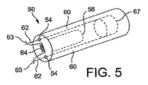
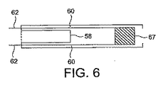
長手部16は中空であり、案内された状態で長手部分16の内面を補完する外面を有するカートリッジ50を受容するよう構成されている。カートリッジは、その前面52が腱係合面26に向いた状態で間隔縮小部の中に挿入されるよう構成されており、前面52の第1及び第2の開口部54が並設され、以下に詳細に説明するように針の間のループ状の縫合糸とともに各開口部54の外に出で進む針が長穴56を通過できるように、対応する長穴57が腱係合面26に形成されている。
The
図5は、カートリッジ50の概略的な斜視図を示しており、図6は、平面図を示す。カートリッジと案内部材との間に案内通路60を規定する案内部材58が、カートリッジの前端部52から内側に延びている。一対の針又は突起部62が案内通路60の中に配置されており、開口部54を通って出るよう配置可能である。一対の針62がカートリッジの内側の横材67によって結合されている。少なくともカートリッジの部分が、間隔縮小部のパーツとして代替的に実施できることに留意されたい。
FIG. 5 shows a schematic perspective view of the
横材67は、カートリッジ又は間隔縮小部のいずれかに設けられた駆動機構(図示せず)に係合しており、フック8の方向に開口部54及び56を通して針62を進めるよう構成されている。駆動機構は、例えば、ネジ又は手動又は歯車付きの締付機構で実施してもよく、腱及び骨を通して針を「発射」するのに使用する針62又はバネ負荷機構の進入深さの微細な制御が可能である。代替的に、横材67を、ハンマ又は木槌のための接触面を規定するよう構成してもよく、接触面を軽く叩くことによって上述するように前に針を進めることができる。
The
図5に示すように、1本の縫合糸64とともに2つの針が装填されており、縫合糸64の一端63がそれぞれ対応する針62の目穴を通っている。縫合糸は、縫合糸の比較的短い端部が針の各端部から突出するように構成されており、残りの部分の縫合糸が2つの針62の間で巻かれ又はそうでなければ格納されている。
As shown in FIG. 5, two needles are loaded together with one
使用の際に、図7に示すように、針62及び縫合糸64が、大結節34を通り抜ける縫合糸の横断通路の内側に斜筋を形成して上腕頭の外側に出てくるように、回旋腱板の腱及び上腕頭42を通って進む。
In use, as shown in FIG. 7, so that the
縫合糸が上腕頭の外側に出るときに縫合糸を掴んで固定するための多くの選択が予想される。 Many options are envisioned for grasping and securing the suture as it exits the humeral head.
ある実施例では、フック8が、長手軸24と交わる位置で縫合糸マットが大結節の外側面に押し付けられて保持されるように、縫合糸マットを保持するためのホルダを規定する。ホルダは、器具が修復のために所定の位置にある場合に縫合糸マットが結節の外側面と接触するが、縫合糸マットによって縫合糸64を捕らえた後に器具を外すと縫合糸マットを非常に容易に解放できるように、十分にしっかりと所定の位置に縫合糸マットを保持するよう構成されている。
In one embodiment, the hook 8 defines a holder for holding the suture mat so that the suture mat is held against the outer surface of the large nodule at a location that intersects the
針及び縫合糸は、それらが外側面に出てきて縫合糸マットに穴を開け縫合糸の自由端63が縫合糸マットを横切るまで骨を通って進む。これにより、縫合糸が、このような目的に適した材料でできた縫合糸マットによって捕らえられることで、縫合糸が縫合糸マットによって固定される。横材64の面に取り付けられた回収ひも、又は長手部16の穴の外にカートリッジ50を「押し出す」のに使用できるバネ負荷機構(図示せず)によって、長手部16の穴から縫合糸カートリッジ50を引っ込めることができ、さらに案内されながらカートリッジ50が長手部16の中に受容される。
The needle and suture are advanced through the bone until they emerge on the outer surface and puncture the suture mat until the
縫合糸が縫合糸マットによって固定されると、アームを操作して肩甲骨面で90°よりも大きく関節窩上腕関節を合わせることによって、縫合糸材にかかる張力を減らす。レバー48を動かして爪44を回動させることによって間隔縮小部を解放させることができ、これにより、所定の位置に間隔縮小部を保持するラチェット機構が解放される。そして、フックガイドを手術部位から取り外すことができる。
When the suture is secured by the suture mat, the tension on the suture material is reduced by manipulating the arm to align the glenoid humeral joint greater than 90 ° on the scapula surface. The interval reducing portion can be released by moving the
解放位置を最適化すると、横ポータルから縫合糸を結ぶことができる(主要な縫合ポストに設けられた結び目を摺動させ/固定することで、当業者に既知の方法でポストを切り替え複数のハーフスイッチを設ける前に、結び目を皮質骨に摺動させて、圧力を用いて反対側の縫合糸マットを引くことで固定及びロックする)。代替的に、縫合糸を所定の位置のフックと骨との間で結ぶことができ、器具がさらに遠い横ポータルで係合される。 When the release position is optimized, the suture can be tied from the lateral portal (by sliding / fixing the knot provided on the main suture post, the posts can be switched in a manner known to those skilled in the art. Before providing the switch, slide the knot into the cortical bone and lock and lock by pulling the opposite suture mat with pressure). Alternatively, a suture can be tied between the hook and bone in place, and the instrument is engaged at a farther lateral portal.
針64の先端部66は、縫合糸64を受容するための改良した目穴を有してもよい。図8に示す改良した目穴68は、針を引き出す際に縫合糸が容易に先端部66を滑り出るように、先端部66に向けて開いている。図9に示すように、針が、従来の針の目穴72及び先端部66から延びている長手方向に凹んだ溝部70を規定してもよい。前進する際に針が骨を通り抜けるときに、凹んだ溝部70にある縫合糸は、そうでない場合よりもあまり摩擦を受けない。同じようなことが、針を引っ込める際にも当てはまる。明らかに、図9の実施例の溝部70は、図8の改良した針の開いた目穴68と組み合わせることができる。
The
縫合糸マットによって縫合糸を捕らえるのを、図9の実施例の針が回転可能に取り付けられ縫合糸がカートリッジの中で縫合糸案内部によって案内され引っ張られる構成によって、容易にしてもよい。縫合糸が縫合糸マットに捕らえられると針を回転させることによって(例えば1/4回転、又は90°)、縫合糸の張力が縫合糸を溝部70の外に押し出すよう作用することで、縫合糸マットに捕らえられ易くする。 Capturing the suture by the suture mat may be facilitated by a configuration in which the needle of the embodiment of FIG. 9 is rotatably mounted and the suture is guided and pulled in the cartridge by the suture guide. When the suture is caught by the suture mat, the suture is operated by rotating the needle (for example, 1/4 rotation or 90 °) so that the tension of the suture pushes the suture out of the groove portion 70. Make it easy to be caught by the mat.
さらに、ストッパ又は結び目によって針から縫合糸が引き出されるのが防止される。 Furthermore, the stopper or knot prevents the suture from being pulled out of the needle.
代替的な実施例では、縫合糸に、針によって形成された骨の通路を通って押されるトグルが設けられており、トグルが上腕頭の外側部と係合することによって縫合糸が逆戻りするのを防ぐ。縫合糸はここではトグルによって捕らえられているため、上記の縫合糸マットとともに又は縫合糸マット無しに本実施例を使用してもよい。2つの方法でトグルを使用できる。第1に、上記の実施例と同じように、逆戻りを防ぐためだけにトグルを使用し、上記のように縫合糸を上腕頭の外側面で結ぶ。第2に、トグルを所定の位置に取り外せない状態にして、以下に詳細に説明するように、縫合糸を上ポータルから上腕頭の上部で結ぶ。第1の方法では、比較的短い縫合糸が、縫合糸が上腕頭の外側面の外に出て横ポータルから取り出せるように縫合糸64の自由端63で設けられている。第2の方法では、図10から図12を参照して以下に説明するように、腱の上の自由端63に上ポータルから近付けるのを維持するように、長い縫合糸が自由端63で設けられている。
In an alternative embodiment, the suture is provided with a toggle that is pushed through the bone passage formed by the needle so that the suture can be reversed by engaging the toggle with the outer portion of the humeral head. prevent. Since the suture is here captured by a toggle, this embodiment may be used with or without the suture mat described above. Toggle can be used in two ways. First, as in the previous embodiment, a toggle is used only to prevent reversion, and the suture is tied on the outer surface of the humeral head as described above. Second, the toggle is not removable in place and a suture is tied from the upper portal to the top of the humeral head, as described in detail below. In the first method, a relatively short suture is provided at the
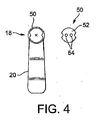
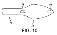
上記のトグルの実施例を具えた使用可能な1つの針が図10に記載されており、比較的厚い先端部74及び(部分74に対して)比較的薄いステム部76を具えている。針穴は、ステム部76との結合部の近くに設けてもよい。図8の実施例の開いた針穴を、図10の(点線の)代替的な針穴80によって概略的に図示するように、より厚い先端部74とともに使用してもよい。図10の針の構成を上記の任意の構成と組み合わせてもよいことに留意されたい。
One usable needle with the toggle embodiment described above is illustrated in FIG. 10 and includes a relatively
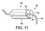
図10の針とともに使用するためのトグル82を図11に概略的に示しており、円筒部材84の外径が厚い先端部74の径よりも細いか又は等しくなるようにステム部76の周りに緩く嵌るよう構成された、弾力性のある中空の円筒部材84を具えている。円筒部84は、先端部74を越えて押すことができるように十分に弾力があるよう構成される。円筒部84は、スリーブ86によって規定される溝部88に設けられる縫合糸64を具えたスリーブ86を有している。
A
使用時に、カートリッジの針のステム部76の周りにトグル82を設けて、縫合糸の自由端63が目穴78又は80に通される。先端部74が上腕頭の外側に完全に出るように針が上腕頭の骨を通して押されると、トグル82が先端部74によって形成された骨の通路を通してステム76に沿って進み、先端部74の先の上腕頭の外側に押し出される。任意の適切な手段、例えば、プランジャタイプの機構によって進めることができる針のステム76の周りに設けられたさらなるスリーブによってトグルを進めてもよい。
In use, a
上記の第1の方法において、双方の針のトグルが上腕頭の外側に配置されると、針が引っ込んでフックガイド及び間隔縮小部が取り外され、上記のようにアームの適切な位置を確かにする。そして、縫合糸の自由端63及びトグル82に横ポータルから近付けることができ、トグルが取り除かれ縫合糸が縫合糸マットとともに上記のように結ばれる。
In the first method described above, when the toggles of both needles are placed outside the humeral head, the needles retract and the hook guides and spacing reductions are removed, ensuring proper arm positioning as described above. To do. The
上記の第2の方法では、自由端63が上ポータルから近付ける状態で腱の上部に残るように、自由端63が十分に長い。図12に示すように修復器具を取り除くと、各針によって形成された通路から突出するトグル82がその部位に残り、縫合糸のループが2つの各トグルを腱の上に付けて、自由端63が上ポータルから近付けるようになる。
In the second method described above, the
トグル82のスリーブ88は、トグルの少なくとも一方の自由端92を残して縫合糸64のトグル82への取付点90がトグルの本体にあるように、トグルの一部のみを覆っており、自由端63を引っ張ることによって縫合糸を張るとトグルが針によって骨の中94に形成された通路に対して横方向の位置に回転し、トグルが骨の外側面96に係合する。そして、好適には、トグル82への縫合糸64の取付点90は、縫合糸64の自由端63を結ぶことによるさらなる固定を要しない十分な張力を与えるが、各通路からの自由端63を適切な方法で腱の上で結ぶことができる。
The
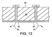
図14に示すように、図13の矢印で示す方向にのみ自由端63を引っ張ることによって縫合糸をトグルに対して動かせるように、通路88に返し98又は任意の適切な一方向を向いた手段を設けてもよい。このような構成により、縫合糸を腱の上で結ぶ必要無しに縫合糸を固定することができるが、当然ながら、自由端63を腱の上で結んで修復箇所を追加的に固定してもよい。
As shown in FIG. 14, means 98 are turned back into
また、例えば、1つの針のみを使用して上記のトグルシステムが他の修復器具に応用され、本発明のさらなる態様では、細長い先端部から延びる針のステム部よりも大きな断面の細長い先端部を有する外科用注射針が設けられていることに留意されたい。さらに、ステム部を囲んでこのような針とともに使用する縫合糸を受容するための長手方向の溝部を規定する弾力性のある材料のスリーブを有するトグルが設けられている。 Also, for example, the toggle system described above may be applied to other repair instruments using only one needle, and in a further aspect of the invention, an elongated tip having a larger cross section than the stem portion of the needle extending from the elongated tip is used. Note that a surgical needle is provided. In addition, a toggle is provided having a sleeve of resilient material surrounding the stem and defining a longitudinal groove for receiving a suture for use with such a needle.
図15は、修復箇所の側面を示す。図16の平面図に示すように、腱36は、好適には、上記のように送り出されるさらなる縫合糸によって上腕頭40に固定される。例えば、縫合糸を1cm間隔で腱の端部の内側に設けて、腱の前部から後部にかけての延長部をカバーしてもよい。
FIG. 15 shows the side of the repair site. As shown in the plan view of FIG. 16, the
フックガイド4の代替的な実施例では、フックガイド及び間隔縮小部6が、図1を参照して説明されているように上ポータル及び横ポータル32双方を通るのではなく、いずれも上ポータルを通って送り出されるよう構成されている。案内部12が代替的なフック8’に取り付けられており、間隔縮小部をその中に受容するよう中空の真っ直ぐな首部10’によって上腕頭に適合するようフック8’が構成されている。器具を組み立てると、首部が間隔縮小部6に沿って案内部12から真っ直ぐに延びる。間隔縮小部と腱との間の接触点の近くで、首部10’が上腕頭の周りを湾曲する。図17の挿入図A,B及びCは、対応する首部10’の断面を示している。
In an alternative embodiment of the hook guide 4, the hook guide and spacing reduction portion 6 do not pass through both the upper portal and the
図18及び図19を参照して記載されている腱修復アッセンブリの代替的な実施例では、腱修復アッセンブリが全体として、上記の実施例に関する間隔縮小部102及び骨係合部106を有している。間隔縮小部102は案内部材104、例えば、アーチ形の案内棒によって骨係合部106に結合されており、駆動機構108が案内部材104の上に乗っていて骨係合部材106に取り付けられている。止めネジ110又は代替的な緩めることができる固定手段によって案内部材104に間隔縮小部材102を固定してもよいが、間隔縮小部102を代わりに案内部材104に固定取付してもよいことに留意されたい。同様に、固定取付で又は取り外し可能に駆動機構108に骨係合部を取り付けてもよい。
In an alternative embodiment of the tendon repair assembly described with reference to FIGS. 18 and 19, the tendon repair assembly generally has a
駆動機構108は、案内部材104に沿って間隔縮小部102及び骨係合部106を互いに関連して移動させるための適切な駆動機構であり、例えば、駆動部材108をねじ式の回転駆動機構に結合してもよい。ある特定の実施例では、駆動機構108が、典型的なコーキングガン又は同じようなディスペンサ構成で通常見られるようなキャッチ・アンド・リリースプレート機構を有している。このような構成では、トリガを押したときに駆動棒を噛んで駆動棒を進めるトリガで動作するキャッチプレートの方法によって、ピストンがコークカートリッジの中に前進し、ピストンを引っ込めることができるよう解放し得る駆動棒を噛む解放可能なブレーキ板によってピストンの後退が阻止される。駆動システム108は、キャッチプレートが機構がトリガ112によって動作して、案内部材104に沿って間隔縮小部材102に向けて骨係合部材106を駆動する同じような構成を有している。従って、このような構成は、使用者の指によって保持される骨係合部106に向けて使用者の手のひらでトリガ112を動作させる点で(典型的なコーキングガンでは、使用者の手のひらに載っているバット(butt)に向けて使用者の指でトリガを動作させる)、上記のコーキングガン駆動機構とは異なる。このため、コーキングガンのピストンの自由端に対応するのは案内部材104の自由端114である。
The
骨係合部106は、その下端部に骨係合部材116を具えており、骨係合部材116は例えば1又はそれ以上のスパイクを有して横ポータル32を通して上腕の皮質骨にしっかりと係合する。骨係合部材116が1つのスパイクから成る場合、修復アッセンブリはこの単一のスパイクの周りを有利に回転し、例えば、患者の頭部を邪魔するのを防止するために、器具の設置時に大きな柔軟性を発揮することが可能である。一方、骨に実質的に固定された関係でアッセンブリを保持する2又はそれ以上のスパイクを使用することによって、もっとしっかりと固定した構成を実現することができる。
The
骨係合部106は、骨係合部106に取り外し可能に結合された案内部材120のために、骨係合部材116の近くの結合構成118を規定する。例えば、結合構成118は、案内部材120に規定されたバイオネットラグ124と係合する骨係合部に規定されたバイオネットスロット122を有するバイオネット結合を具えている。例えば、ネジ式の結合又は爪が係合する結合といった他の適切な結合構成をバイオネット結合の所定の位置で使用できることに留意されたい。結合すると、案内部材120は横ポータル32を通して骨係合部材116とともに送り出されるよう構成されるが、横ポータルを通して上腕骨の側面にさらに近付けることができるよう取り除くか、又は以下に詳細に説明するような代替的な案内部材と交換してもよい。案内部材120は、骨貫通器具を案内するための2つの通路126を規定しており、改めて以下に詳細に説明する。
骨係合部106は、骨係合部が結合構成118の近くにスペーサ部材130によって結合されている結合部材128を具えている。スペーサ部材130の長さを選択して、横ポータルを通した上腕骨の側面への近付き易さと、修復アッセンブリの全体的なコンパクト性とのバランスを取ることができ、長さが長くなると近付き易さが増すが器具の大きさもまた増大する。スペーサ部材130の表面を、案内部材118と共働して案内部材にさらなる支持を与えるような形状にしてもよい。
The
ここで、間隔縮小部102に移ると、これは案内部材104に一端が結合され他端が結合部134を規定する結合部材132を具えている。結合部134は、上記の実施例のように腱係合部26を規定する長手部材16を具えた腱係合部材136を結合部材132に結合するよう構成されている。結合部は、例えば、止めネジ138によって固定された腱係合部材136を受容するスリーブを具えているが、例えば、バイオネット結合又は爪が嵌合する結合といった多くの他の結合部又は機構を使用してもよいことに留意されたい。代わりに、明らかに、腱係合部材136を結合部材132に取り外せないよう固定してもよい。
Here, when moving to the
有利なことに、結合部材132に腱係合部136を取外可能に結合することによって、従来のカニューレのような従来の方法で腱係合部を上ポータルを通して配置して、その後でこの構成の残りの部分に所定の位置で結合することができる。一方の側の腱係合部材の横断方向の寸法及び他方の側の骨係合部材116及び案内部材120の横断方向の寸法は、関節鏡のポータルを通してそれらを設置するための適切な寸法、例えば10mmをそれぞれ超えてはならない。特に、細長い部材16は、8mmから10mmの標準的な直径を有している。
Advantageously, the
肩の十分なクリアランスを提供するために、結合部材128及び132は約10−15cmの長さを有しており、腱係合面に対して約15−20cmの対応する曲率半径を規定する。例えば、入れ子構成によって調整可能な長さを有するようこの部材を構成してもよいことに留意されたい。
To provide sufficient shoulder clearance,
代替的な実施例では、図19に関して図示されているように、結合部材132及び128が互いに交差するよう細長く、回動軸140によって互いに回動可能に固定されている。一方向保持部材142が結合部材の一方、例えば結合部材132に固定されており、他方の結合部材、例えば結合部材128の対応する部分に係合して一方向クラッチを規定する。例えば、結合部材128の接触領域144と保持部材142との間のラチェット機構としてこれを実施してもよいが、例えば偏心カム構成といった一方向摩擦クラッチで保持される滑面の保持部材のような他の一方向機構が同様に予想される。また、一方向機構を回動軸40に組み込むか又はこれと併せてもよいことに留意されたい。
In an alternative embodiment, as illustrated with respect to FIG. 19, the
使用時に、使用者は、腱係合面26が腱を押して上記のように内側から外側に間隔を小さくして上記のように骨係合部106に向けて回動軸140の周りを移動させるように、骨係合部106に向けて間隔縮小部102を強く押す。そのために、結合部材132及び128は、使用者の手のひら及び指の中で保持され易くして2つの部分を一緒に強く押すことができるような形状の部分を有している。図20に示すさらなる代替的な構成では、使用者の指を受容するための操作部146が、例えば間隔縮小部102の一方の部分に設けられており、2つの部分を一緒に強く押し易くなっている。さらに別の代替的な実施例では、2つの結合部132及び128が回動軸140を越えて延びて各把持部148及び150を終端とすることで鉗子状の構成となっており、このような構成では、把持部148及び150を一緒に強く押すことによって、腱係合部材136が骨係合部材116に向けて進む。
At the time of use, the user pushes the tendon to move the
駆動機構114を動かすか又は図19から図21を参照して説明したように結合部材128及び132又は把持部150及び148を一緒に強く押すと、腱係合部材136の腱係合面26が、それぞれアーチ形の案内部材104又は結合部材128及び132の長さとともに回動軸140によって規定されるアーチ形の軌道で骨係合部材116に向かって進む。当然ながら、図18Aに関連する上記の実施例のケースでは、案内部材104の曲率半径を無限大としてもよく、これにより図1に関する上記の実施例のように腱係合面の軌道が直線状となる。しかしながら、(腱係合部材136に関する)腱係合面26のアーチ形の軌道を規定することによって、後者の実施例は、骨係合部材130及び腱係合部材136に対するより効果的な、より急勾配の迎え角が可能となり、上ポータルを通して腱に近付き易くなり、以下のように上腕骨を通る縫合糸の穴もアーチ形でよいため、さらなる骨材料が縫合糸の上に配置されると、上腕骨の上面から逸れて曲がる骨の通路のアーチ形の形状により、より確実な修復の可能性がある。
When the drive mechanism 114 is moved or when the
間隔の縮小及び縫合動作が損傷した腱の内側で実行される図1に関する上記の実施例とは対照的に、図18に関して説明される実施例は、大部分が外側で実行される。腱係合部が腱に係合し、上記のように骨係合部に向けて腱係合部を進めることによって間隔を小さくすると、縫合糸の通路が横ポータルを通って損傷した腱の外側に形成される。 In contrast to the embodiment described above with respect to FIG. 1 in which the spacing reduction and stitching operations are performed inside the damaged tendon, the embodiment described with respect to FIG. 18 is largely performed outside. When the tendon engagement portion engages the tendon and the distance is reduced by advancing the tendon engagement portion toward the bone engagement portion as described above, the suture passage is outside the damaged tendon through the lateral portal. Formed.
第1のステップで、真っ直ぐな通路を有する第1の案内部材を、骨係合部に対して腱係合面の軌道の延長部が交差する上腕骨の皮質骨の位置にドリルビットを案内するために使用する。固い皮質骨にドリルビットが貫通すると、案内部材が、骨係合部(それは腱係合面の軌道と同じ曲率半径を有して同心である)に対する腱係合面の軌道の延長部と一致する曲がった通路を有する第2の案内部材と入れ替わり、十分な硬さを有して上腕頭の軟らかい海綿骨に貫通する際に形状を維持する適切な形状のキルシュナー鋼線といった、曲がった骨貫通部材を案内する。キルシュナー鋼線を、例えば1から1.5mmの直径を有する硬化ステンレス鋼で作成してもよく、海綿骨に貫通させるためのトロカールの先端部を設けてもよい。第2の案内部材によって案内されて、骨貫通部材が海綿骨を通って進み、腱係合面26の特定の位置に達する。
In a first step, a first guide member having a straight passage is guided to the position of the cortical bone of the humerus where the extension of the trajectory of the tendon engaging surface intersects the bone engaging portion. Use for. When the drill bit penetrates the hard cortical bone, the guide member coincides with the extension of the trajectory of the tendon engagement surface relative to the bone engagement portion (which is concentric with the same radius of curvature as the trajectory of the tendon engagement surface) Bent bone penetration, such as an appropriately shaped Kirschner steel wire that replaces the second guide member with a curved passageway that has sufficient hardness to maintain its shape as it penetrates the soft cancellous bone of the humeral head Guide the member. The Kirschner steel wire may be made of hardened stainless steel having a diameter of 1 to 1.5 mm, for example, and may be provided with a trocar tip for penetrating the cancellous bone. Guided by the second guide member, the bone penetrating member advances through the cancellous bone and reaches a specific location on the
間隔縮小部102と骨係合部106との間の角距離と無関係な特定の位置で腱係合面に達するために、骨貫通部材の曲率半径は、骨係合部106に対する腱係合面22の軌道の曲率半径と略同一である必要があり、案内部材120の曲がった通路により、海綿骨を通る貫通通路が間隔縮小部102及び骨係合部106によって規定される面内にある可能性があることを保証する。
In order to reach the tendon engagement surface at a specific position independent of the angular distance between the
当然ながら、腱係合面の軌道が直線で構成されている場合、案内部材の通路及び骨貫通部材もまた直線構成である必要があることに留意されたい(このようなケースでは、ドリルビットを用いて上腕頭及び腱と向かい合う腱係合面26に抜ける真っ直ぐな骨の穴を開けてもよい)。
Of course, it should be noted that if the trajectory of the tendon engagement surface is configured in a straight line, the guide member passage and the bone penetrating member must also be configured in a straight line (in such a case, the drill bit must be And may be used to drill straight bone holes through the
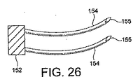
図26を参照すると、骨貫通アッセンブリの特定の実施例が、横材152によってそれぞれの先端部155とは反対側の端部が結合された上記のようなキルシュナー鋼線といった2つの骨貫通部材154を有しており、2つの骨貫通部材が1つの動作で同時に骨を通って進むことで、修復に要するステップを減らす。横材152は、貫通部材154が案内部材120の通路126間の距離に対応する距離の間隔を有するのを保持する。
Referring to FIG. 26, a particular embodiment of a bone penetrating assembly includes two
上記のように、修復は腱の取付部位での骨の切除を含んでよく、腱の取付をし易くする。同様に骨の切除は、取付部位における局所的脆弱化又は海面骨の完全な切除により、上腕頭の内側において骨貫通部材を抜け出し易くするであろう。 As noted above, the repair may include bone resection at the tendon attachment site to facilitate tendon attachment. Similarly, bone resection will facilitate dislodging of the bone penetrating member inside the humeral head by local weakening at the attachment site or complete resection of the sea surface bone.
腱が取付部位に変形して腱係合面26によって所定の位置に保持されると、それぞれの骨の通路に一端を通し横ポータルを通して上腕骨の外側面に縫合糸を固定又は結ぶことにより、長い縫合糸で腱を縫合することによって修復が完了する。そのために、腱係合面は縫合糸が内側から横ポータルの外側に取り出される(図22Aに示すような)開口56を規定する。腱の細長い面が部材の壁の自由表面に対応するように、開口56は中空の細長部材16の内径に対応することに留意されたい。腱係合面は、図1及び図3に関する上記の実施例で使用するのと実質的に同じ種類でよく、返しが設けられ又は模様が付けられていて、腱との確実な係合を確保する。
When the tendon is deformed into the attachment site and held in place by the
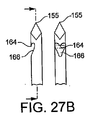
特定の実施例に従った中空の細長部材16にわたる断面を示す図22Bを参照すると、中空の細長部材の内部が、以下に詳細に説明するようにフックと係合するための縫合糸の短い部分158を与えるための縫合糸保持構造156と、縫合糸の残りの部分162を収容するための縫合糸収容区画160とを具えている。
Referring to FIG. 22B, which shows a cross-section through a hollow
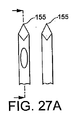
図27Bを参照すると、上記のフックは、先端部155の近くの凹部166の突出部として形成されるフック164として先端部155の近くに形成してもよい。骨貫通部材154が上腕骨及び固定した腱を通って移動する際に、フックが縫合糸の短い部分158と係合するように、骨貫通部材154が所定の位置の開口56を通って部材16の中に入る。続いて、骨貫通部材154を取って縫合糸の短い部分158とともにこれを引き出す。これにより、縫合糸の残りの部分162が上腕骨の中の骨貫通部材154によって開けられた骨の各通路を通る。
Referring to FIG. 27B, the hook may be formed near the
骨の穴を通して2倍の長さの縫合糸を配置してより強固に修復するように、縫合糸のループとして縫合糸を設けてもよく、又は代替的に1本の縫合糸又は縫合糸のポール(pole)を有してもよい。後者のケースでは、縫合糸先進構造156によって縫合糸の自由端が解放できるよう保持され、上腕骨を通して骨貫通部材154を引っ込める際に自由端がフック164から確実に外れにようにする一方で、骨貫通部材154が上腕骨を通って完全に引っ込められると構造156から自由端を外すことができ、その後、自由端が骨の通路を通って追随することができることで、骨の通路を通して1本の縫合糸を配置する。
The suture may be provided as a loop of suture so that a double length of suture is placed through the hole in the bone for more robust repair, or alternatively a single suture or suture You may have a pole. In the latter case, the
図22Cを参照して説明される代替的な実施例では、中空の部材16は内部が空であり、腱係合面26の反対側の端部で開口端168(図18A及び19)を規定する。この実施例では、対応する骨貫通部材が(フックを同じように使用することができるが)図27Aに示すように先端部155の近くの開口170を規定する。先端部が腱の取付部位を通過すると骨貫通部材がさらに押されて本体が開口端168を通って外に出て、本体の外側で手によって開口170に縫合糸を通すことができる。1本の縫合糸をそれぞれの骨貫通部材154の開口に通した後に縫合糸をループ状にして2本の縫合糸を骨の通路に通すか、又は上記のように骨の通路を通して取り出すよう自由端を残すように、縫合糸を開口170に通してもよい。
In an alternative embodiment described with reference to FIG. 22C, the
図23A及び図23Bを参照して説明するさらに別の実施例では、腱係合面26が部材16の固体内部の空洞によって規定され、又は中空の細長い部材16内部の曲管といった構造を規定する適切な通路によって規定される通路174で繋がった2つの開口172を有している。このような実施例を用いるために、上記のように穴を開けることによって(修復器具が腱係合面の直線状の軌道を規定する実施例)又はキルシュナー鋼線によって、骨の通路が予め作成される。開口172に隣接するように骨の通路が設けられると、1本の縫合糸が一方の骨の通路に通され、他方の骨の通路を通して戻すための通路172に通される。代替的に、縫合糸を適切な柔軟性のあるガイドワイヤで直列式に連結できる。
In yet another embodiment described with reference to FIGS. 23A and 23B, the
骨の通路を通して縫合糸が配置され、上腕骨の外面に自由に出入りできるようになると、結び目を形成することによって縫合糸が所定の位置に固定される。縫合糸を固定する前に、縫合糸マットが上腕骨に向けて縫合糸に押し付けられ、結び目が縫合糸マットの上に形成される。縫合糸のポール又はループ又は上腕骨に押し付けられる一方向の縫合糸マットを使用することによって、修復器具を用いた損傷した回旋腱板の関節鏡下による修復で要する外科的な技能がさらに低くなり、上腕骨に向けてほぼ一方向のみに縫合糸に沿ってマットを動かすことができる。このように、縫合糸マットを上腕骨に押し付けてもよく、それに続いて結び目を形成して縫合糸を固定する必要性無しに、縫合糸を張る。 When the suture is placed through the bone passage and can freely enter and exit the outer surface of the humerus, the suture is secured in place by forming a knot. Prior to securing the suture, the suture mat is pressed against the suture toward the humerus and a knot is formed on the suture mat. The use of a suture pole or loop or unidirectional suture mat that is pressed against the humerus further reduces the surgical skills required for arthroscopic repair of a damaged rotator cuff using a repair device. The mat can be moved along the suture in only one direction toward the humerus. In this way, the suture mat may be pressed against the humerus, followed by tensioning the suture without the need to form a knot to secure the suture.
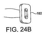
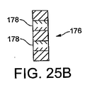
図25A及び図25Bを参照すると、適切な一方向縫合糸マットが、通路に対して角を成す関係で通路の壁に沿って配置された部材又は返し(barbs)を具えた縫合糸通路178を有しており、通路を通り抜ける縫合糸が一方の方向(返しに逆らう角度)に係合及び留められ、逆の方向(返しの角度)に取り外される。代替的に、一方向の縫合糸マットの代わりに、図14に関する上記のような一方向トグル機構を縫合糸の各ポール又はループに使用してもよい。
Referring to FIGS. 25A and 25B, a suitable one-way suture mat includes a
都合の良いことに、これらの一方向構成は、固定した状態で縫合糸を連続的に引っ張るように張力の下で縫合糸を通って上腕骨に移動する。これは、結び目等を形成する際に張力を失う可能性を防止することで、満足のいくよう処置を終わらせるために要する関節鏡視下手術の技能のレベルをさらに下げる。 Conveniently, these one-way configurations move through the suture to the humerus under tension so as to continuously pull the suture in a fixed state. This further reduces the level of arthroscopic surgery skills required to complete the procedure satisfactorily by preventing the possibility of losing tension when forming knots and the like.
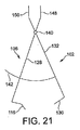
縫合糸の腱の側に圧力減少又は力の分布を与えるために、図24A及び図24Bにそれぞれ示すように、縫合糸のほぼ中間に繋ぎ目180を形成するよう縫合糸を繋ぐか、又は縫合糸を縫合糸マット182の上で滑らせてもよい。骨の穴を通る2倍の長さの縫合糸のループでこれを同様に行うことができるか、又は代替的に、ループを繋ぎ目180又は縫合糸マット182の両側に取り付けてもよいことに留意されたい。
To provide pressure reduction or force distribution on the side of the suture tendon, the suture may be tied or sutured to form a
圧力減少又は力の分配器具を含む縫合糸材料を、中空の細長部材16の中に挿入可能で図22Bを参照して上述したような縫合糸先進構造156を規定するカートリッジに設けてもよい。開口端168又は開口56を通してカートリッジを部材16の中に挿入してもよい。
A suture material including a pressure reducing or force distribution device may be provided in a cartridge that can be inserted into the hollow
上記の説明は単なる一例であり、多くのお改良、変更、並置及び上記の態様の新たな組み合わせが当業者によって導き出せることに留意されたい。損傷した回旋腱板に関して上記の実施例を記載したが、本方法及び実施例は、損傷した腱を骨に取り付ける必要がある他の負傷の修復に適用される。このため、本発明の範囲は上記の記載によって限定されないが、添付の特許請求の範囲の記載によって判断される。 It should be noted that the above description is merely an example and that many improvements, modifications, juxtapositions and new combinations of the above aspects can be derived by those skilled in the art. Although the above example has been described with respect to a damaged rotator cuff, the method and example apply to repairing other injuries that require the damaged tendon to be attached to the bone. Therefore, the scope of the present invention is not limited by the above description, but is determined by the description of the appended claims.
Claims (22)
前記取付部位の反対側の骨の部分に係合するための骨係合部(106)と、
取付部位(40)に腱(36)を押し付けるための腱係合面(26)を規定する腱係合部(16)を一端に有する中空の細長部を具える間隔縮小部(102)と、
中空の細長部の内側に挿入される外形形状を有し、かつ、1つのループに形成された縫合糸の、略均等に離間した2箇所の部分をそれぞれ小円状に保持する2つの区画(156)と、当該区画外であって、縫合糸の残りの部分を収容する独立した別区画(160)とからなる縫合糸カートリッジと、
前記骨係合部を前記間隔縮小部に結合するための第1の案内部材であって、前記骨係合部(106)及び前記間隔縮小部(102)を、使用時に互いに対して移動可能に固定する第1の案内部材と、
2つの骨貫通部材を有する骨貫通器具であって、それぞれの骨貫通部材がその先端の近くに形成されたフックを有する骨貫通器具と、
を有しており、
前記骨係合部が、2つの平行な通路を規定する第2の案内部材を有しており、前記腱係合面に向かう方向に同時に2つの前記骨貫通部材を案内して、縫合糸のループをそのそれぞれのフックに係合させることを特徴とする腱修復アッセンブリ。 A tendon repair assembly for securing a damaged tendon (36) to a bone attachment site (40) comprising:
A bone engaging portion (106) for engaging a portion of the bone opposite the attachment site;
An interval reduction portion (102) comprising a hollow elongate portion having at one end a tendon engagement portion (16) defining a tendon engagement surface (26) for pressing the tendon (36) against the attachment site (40);
Two sections having outer shapes inserted inside the hollow elongated portions and holding two portions of the suture thread formed in one loop, which are approximately equally spaced apart, in a small circle shape ( 156) and a separate cartridge (160) outside the compartment and containing a separate portion of the suture,
A first guide member for coupling the bone engaging portion to the gap reducing portion, the bone engaging portion (106) and the gap reducing portion (102), with respect to each other physician during use A first guide member fixed movably;
A bone penetrating device having two bone penetrating members, each bone penetrating member having a hook formed near its tip;
Have
The bone engaging portion has a second guide member defining two parallel passages, and simultaneously guides the two bone penetrating members in a direction toward the tendon engaging surface, A tendon repair assembly characterized by engaging a loop with its respective hook.
前記骨係合部(106)が、肩の側部を通して送出されることを特徴とする請求項1又は2に記載の腱修復アッセンブリ。 The tendon engaging portion (16), sent by through the top of the shoulder,
It said bone engaging portion (106), tendon repair assembly as claimed in claim 1 or 2, characterized in that it is sent out through the shoulder side.
変位機構(108)が、前記間隔縮小部(102)及び骨係合部(106)のうちの他方に取り付けられ、前記第1の案内部材(104)に沿って前記間隔縮小部(102)及び骨係合部(106)のうちの他方を動かすことを特徴とする請求項1から3のいずれか1項に記載の腱修復アッセンブリ。 The first guide member (104) is attached to one of the spacing reduction portion (102) and the bone engagement portion (106);
A displacement mechanism (108) is attached to the other one of the interval reducing portion (102) and the bone engaging portion (106), and is arranged along the first guide member (104). The tendon repair assembly according to any one of claims 1 to 3, characterized in that the other of the bone engaging portions (106) is moved.
前記骨係合部(106)が、骨貫通器具を案内するための案内部(120)を前記骨係合部材(116)の近くに有していることを特徴とする請求項10に記載の腱修復アッセンブリ。 The bone engaging part (106) has a coupling part for coupling a guide part (120) for guiding a bone penetrating instrument to the bone engaging part near the bone engaging member (116). Or
11. The bone engaging part (106) according to claim 10, wherein the bone engaging part (106) has a guide part (120) for guiding a bone penetrating instrument in the vicinity of the bone engaging member (116). Tendon repair assembly.
前記腱係合面(26)がその中に開口部(56)を規定することにより、前記開口部及び前記自由端を通って前記腱係合部(16)の外側にアクセスできることを特徴とする請求項1から13のいずれか1項に記載の腱修復アッセンブリ。 A hollow elongate member has a free end opening on the opposite side of the tendon engagement surface (26);
The tendon engagement surface (26) defines an opening (56) therein to allow access to the outside of the tendon engagement portion (16) through the opening and the free end. The tendon repair assembly according to any one of claims 1 to 13.
当該腱係合部材(16)が、長手軸と、前記長手軸に対して傾いており開口部を規定する腱係合面(26)とを規定し、
前記腱係合面が、返しを具えており(barbed)、前記腱との確実な係合を確保し、
前記腱係合部材が、中空の細長部を具えており、前記中空の細長部の中に挿入される縫合材(162)を収容するための縫合糸区画(160)を有する縫合糸カートリッジを具え、前記開口部を通してフック(164)を引き出すことによって縫合材(162)を取り出せるように、前記縫合糸カートリッジが前記腱係合面に縫合糸のループを形成するよう構成されていることを特徴とする腱係合部材(16)。 A tendon engagement member (16) for a tendon repair assembly according to any one of the preceding claims,
The tendon engagement member (16) defines a longitudinal axis and a tendon engagement surface (26) that is inclined relative to the longitudinal axis and defines an opening;
The tendon engagement surface is barbed to ensure a secure engagement with the tendon;
The tendon engaging member comprises a hollow elongate portion and comprises a suture cartridge having a suture section (160) for receiving a suture (162) inserted into the hollow elongate portion. The suture cartridge is configured to form a suture loop on the tendon engagement surface so that the suture (162) can be removed by pulling the hook (164) through the opening. A tendon engaging member (16).
前記骨貫通器具が、骨に形成された1対の平行な通路を通って通過し前記腱修復アッセンブリの骨係合部の第2の案内部材に形成された2つの平行な通路に受け入れ可能である2つの細長い骨貫通部材(154)を有しており、
それぞれの細長い骨貫通部材がその一端の先端部を有しており、それぞれの細長い骨貫通部材が前記先端部(155)の近くに形成されたフックを有しており、
前記骨貫通部材(154)の前記先端部(155)とは反対側の端部が、横材(152)によって結合されていることを特徴とする骨貫通アッセンブリ。 A bone penetrating device for tendon repair assembly as claimed in any one of claims 1 19,
The bone penetrating instrument is receivable in two parallel passages formed through a pair of parallel passages formed in the bone and formed in the second guide member of the bone engaging portion of the tendon repair assembly. has some two elongated bone penetrating member (154),
Each elongated bone penetrating member has a tip at one end thereof, and each elongated bone penetrating member has a hook formed near the tip (155);
The bone penetrating assembly, wherein an end portion of the bone penetrating member (154) opposite to the distal end portion (155) is joined by a cross member (152).
前記細長い骨貫通部材の先端が、トロカール先端部(155)であることを特徴とする骨貫通アッセンブリ。 A bone penetrating assembly for a tendon repair assembly according to claim 20 comprising :
A bone penetrating assembly, wherein the tip of the elongated bone penetrating member is a trocar tip (155).
Applications Claiming Priority (3)
| Application Number | Priority Date | Filing Date | Title |
|---|---|---|---|
| GBGB0607958.6A GB0607958D0 (en) | 2006-04-21 | 2006-04-21 | Tendon repair |
| GB0607958.6 | 2006-04-21 | ||
| PCT/GB2007/001442 WO2007125279A2 (en) | 2006-04-21 | 2007-04-20 | Tendon repair |
Publications (3)
| Publication Number | Publication Date |
|---|---|
| JP2009538639A JP2009538639A (en) | 2009-11-12 |
| JP2009538639A5 JP2009538639A5 (en) | 2010-06-03 |
| JP5367564B2 true JP5367564B2 (en) | 2013-12-11 |
Family
ID=36581054
Family Applications (1)
| Application Number | Title | Priority Date | Filing Date |
|---|---|---|---|
| JP2009505958A Expired - Fee Related JP5367564B2 (en) | 2006-04-21 | 2007-04-20 | Tendon repair assembly, tendon engagement member and bone penetration assembly |
Country Status (10)
| Country | Link |
|---|---|
| US (2) | US8409225B2 (en) |
| EP (1) | EP2012675B1 (en) |
| JP (1) | JP5367564B2 (en) |
| CN (2) | CN101472527B (en) |
| AT (1) | ATE481037T1 (en) |
| CA (1) | CA2649818A1 (en) |
| DE (1) | DE602007009211D1 (en) |
| ES (1) | ES2351389T3 (en) |
| GB (1) | GB0607958D0 (en) |
| WO (1) | WO2007125279A2 (en) |
Families Citing this family (56)
| Publication number | Priority date | Publication date | Assignee | Title |
|---|---|---|---|---|
| US20090318960A1 (en) * | 2006-02-01 | 2009-12-24 | Burkhart Stephen S | Method of knotless tissue fixation with criss-cross suture pattern |
| EP1987779B1 (en) * | 2007-05-02 | 2016-04-13 | Arthrex, Inc. | Suture tensioning device |
| US20100121337A1 (en) * | 2008-11-13 | 2010-05-13 | Pandya Rajiv D | Device for drilling angled osteal tunnels |
| WO2010081096A2 (en) | 2009-01-12 | 2010-07-15 | Option 3, Llc | Apparatus and methods for tissue closure |
| ES2641774T3 (en) | 2009-07-15 | 2017-11-13 | Pivot Medical, Inc. | Apparatus for treating a coxofemoral joint, including the provision and use of a new suture pin |
| US9198655B2 (en) | 2009-07-15 | 2015-12-01 | Pivot Medical, Inc. | Method and apparatus for treating a hip joint, including the provision and use of a novel suture passer |
| US8568428B2 (en) * | 2011-01-05 | 2013-10-29 | Coloplast A/S | Suture system and assembly including a tubular leader having a clasp |
| US9220495B2 (en) | 2011-02-10 | 2015-12-29 | Coloplast A/S | Suture system and assembly including a suture clip |
| US8591528B2 (en) | 2011-02-24 | 2013-11-26 | Coloplast A/S | Suture system and assembly including a suture cap formed around a tubular sleeve |
| AU2012250548B2 (en) | 2011-05-06 | 2016-11-17 | Linvatec Corporation | Soft anchor made from suture filament and suture tape |
| US8801727B2 (en) | 2011-07-08 | 2014-08-12 | Smith & Nephew, Inc. | Orthopedic suture passer and method |
| US8784427B2 (en) | 2011-07-08 | 2014-07-22 | Smith & Nephew, Inc. | Orthopedic guide and method |
| US8951263B2 (en) | 2011-07-08 | 2015-02-10 | Smith & Nephew, Inc. | Orthopedic suture passer and method |
| US9782165B2 (en) | 2011-11-11 | 2017-10-10 | VentureMD Innovations, LLC | Transosseous attachment |
| US10675014B2 (en) | 2011-11-16 | 2020-06-09 | Crossroads Extremity Systems, Llc | Knotless soft tissue attachment |
| US10470756B2 (en) | 2011-11-16 | 2019-11-12 | VentureMD Innovations, LLC | Suture anchor and method |
| US9131937B2 (en) | 2011-11-16 | 2015-09-15 | VentureMD Innovations, LLC | Suture anchor |
| US10548585B2 (en) | 2011-11-16 | 2020-02-04 | VentureMD Innovations, LLC | Soft tissue attachment |
| CA2860645C (en) | 2012-01-04 | 2019-11-05 | Teleflex Medical Incorporated | Apparatus and methods for tissue closure |
| US10194967B2 (en) * | 2012-09-21 | 2019-02-05 | Atlas Spine, Inc. | Minimally invasive spine surgery instruments: guide wire handle with a guide wire locking mechanism |
| ES2552940T3 (en) | 2012-11-14 | 2015-12-03 | Biedermann Technologies Gmbh & Co. Kg | Aiming device to guide a drilling arrangement |
| US9687221B2 (en) | 2013-02-13 | 2017-06-27 | Venture MD Innovations, LLC | Method of anchoring a suture |
| US9610069B2 (en) * | 2013-04-26 | 2017-04-04 | Medtronic-Xomed, Inc. | Tissue stabilization and repair device |
| US10363126B1 (en) | 2013-05-17 | 2019-07-30 | W. David Hovis | Arthroscopic tenodesis tool |
| US9655714B1 (en) * | 2013-05-17 | 2017-05-23 | W. David Hovis | Arthroscopic tenodesis tool |
| US9277951B1 (en) * | 2013-05-17 | 2016-03-08 | W. David Hovis | Arthroscopic tenodesis tool |
| CN107106177A (en) * | 2014-11-13 | 2017-08-29 | 安东尼奥·桑布瑟蒂 | Absorbable device for reconstructing the gyratory cuff |
| US10058325B2 (en) | 2015-05-19 | 2018-08-28 | Arthrex, Inc. | Suture passer and method of tissue repair |
| US9962174B2 (en) | 2015-07-17 | 2018-05-08 | Kator, Llc | Transosseous method |
| US10154868B2 (en) * | 2015-07-17 | 2018-12-18 | Kator, Llc | Transosseous method |
| US10820918B2 (en) | 2015-07-17 | 2020-11-03 | Crossroads Extremity Systems, Llc | Transosseous guide and method |
| US9888997B2 (en) * | 2015-07-20 | 2018-02-13 | Arthrex, Inc. | Soft anchor assembly with barbed flexible strand and techniques for use |
| US12383253B2 (en) | 2015-08-04 | 2025-08-12 | Crossroads Extremity Systems, Llc | Suture anchor |
| US10226243B2 (en) | 2015-08-04 | 2019-03-12 | Kator, Llc | Transosseous suture anchor |
| CN105411657B (en) * | 2015-12-23 | 2018-06-05 | 雷俊虎 | Orthopaedics glenoid lip of articulation of humerus fix tool system |
| US11419684B2 (en) | 2016-02-19 | 2022-08-23 | Rajiv D. Pandya | System and technique for accessing extra articular lesions or abnormalities or intra osseous lesions or bone marrow lesions |
| US11376079B2 (en) | 2016-02-19 | 2022-07-05 | Rajiv D. Pandya | System and technique for accessing extra articular lesions or abnormalities or intra osseous lesions or bone marrow lesions |
| US10064633B2 (en) | 2016-02-19 | 2018-09-04 | Rajiv D. Pandya | System and technique for accessing extra articular lesions or abnormalities or intra osseous lesions or bone marrow lesions |
| US9925010B2 (en) | 2016-02-19 | 2018-03-27 | Rajiv D. Pandya | System and technique for accessing extra articular lesions or abnormalities or intra osseous lesions or bone marrow lesions |
| US12377193B2 (en) * | 2016-07-06 | 2025-08-05 | The Children's Medical Center Corporation | Indirect method of articular tissue repair |
| CN107961068A (en) * | 2016-10-20 | 2018-04-27 | 练克俭 | A kind of parallel angle guider used in internal fixation of fracture |
| AU2017380830B2 (en) * | 2016-12-21 | 2020-10-08 | Trimed Inc. | A plantar plate repair device |
| US11298143B2 (en) * | 2017-04-12 | 2022-04-12 | Smith & Nephew, Inc. | Surgical drill guide systems and methods of use thereof |
| US10065207B1 (en) * | 2017-04-21 | 2018-09-04 | Hossein KARBAKHSH | Expandable caulking gun with display system |
| US12059148B2 (en) | 2017-06-05 | 2024-08-13 | Conmed Corporation | Suture system and related methods for connecting and creating suspension between at least two bodies |
| US11911019B2 (en) | 2017-07-13 | 2024-02-27 | Conmed Corporation | All-suture anchor |
| GB2569171B (en) * | 2017-12-08 | 2020-09-16 | Ip2Ipo Innovations Ltd | A sewing device |
| WO2019217345A1 (en) | 2018-05-09 | 2019-11-14 | Conmed Corporation | Coined suture passing drill |
| US12364490B2 (en) | 2018-10-12 | 2025-07-22 | Conmed Corporation | Drill guide assembly |
| CN111265261A (en) * | 2020-03-23 | 2020-06-12 | 苏州市永旭精密五金制品厂 | Electric powered rotator cuff repair device |
| WO2022182567A1 (en) | 2021-02-25 | 2022-09-01 | Stryker Corporation | Devices and methods for passing and retrieving suture through tissue |
| US12484904B2 (en) | 2021-06-10 | 2025-12-02 | Cilag Gmbh International | Systems, devices and methods of repairing tendons and ligaments |
| USD976402S1 (en) | 2021-06-10 | 2023-01-24 | Cilag Gmbh International | Bidirectional barbed suture |
| US11963688B2 (en) | 2021-11-20 | 2024-04-23 | Panorthopaedics, Inc. | Device adapted for lateral engagement of an elongated member |
| WO2025151146A1 (en) * | 2024-01-12 | 2025-07-17 | Arthrex, Inc. | Suture locking devices for performing tensionable knotless surgical procedures |
| CN120814862B (en) * | 2025-09-19 | 2025-11-18 | 上海交通大学医学院附属新华医院 | A shoulder and sleeve sewing thread guide device |
Family Cites Families (26)
| Publication number | Priority date | Publication date | Assignee | Title |
|---|---|---|---|---|
| US4198712A (en) * | 1978-10-13 | 1980-04-22 | Swanson Alfred B | Scaphoid implant |
| US4738255A (en) * | 1986-04-07 | 1988-04-19 | Biotron Labs, Inc. | Suture anchor system |
| US5222977A (en) * | 1992-02-21 | 1993-06-29 | Esser Rene D | Surgical needle with an adjustable eye |
| US5250055A (en) * | 1992-06-08 | 1993-10-05 | Orthopedic Systems Inc. | Method and apparatus for tying suture to bone |
| US5312412A (en) * | 1993-02-03 | 1994-05-17 | Whipple Terry L | Fixation alignment guide for surgical use |
| US5330468A (en) * | 1993-10-12 | 1994-07-19 | Burkhart Stephen S | Drill guide device for arthroscopic surgery |
| US5466243A (en) * | 1994-02-17 | 1995-11-14 | Arthrex, Inc. | Method and apparatus for installing a suture anchor through a hollow cannulated grasper |
| WO1995022288A1 (en) | 1994-02-17 | 1995-08-24 | Arthrex, Inc. | Method and device for the arthroscopic reattachment of torn tissues, in particular of torn rotator sheaths |
| US5584839A (en) * | 1994-12-12 | 1996-12-17 | Gieringer; Robert E. | Intraarticular drill guide and arthroscopic methods |
| US6117144A (en) * | 1995-08-24 | 2000-09-12 | Sutura, Inc. | Suturing device and method for sealing an opening in a blood vessel or other biological structure |
| CN2248044Y (en) * | 1995-09-12 | 1997-02-26 | 孙秀玲 | Medical operation thread fixing holder |
| US5681333A (en) * | 1995-11-08 | 1997-10-28 | Arthrex, Inc. | Method and apparatus for arthroscopic rotator cuff repair utilizing bone tunnels for suture attachment |
| US6491714B1 (en) | 1996-05-03 | 2002-12-10 | William F. Bennett | Surgical tissue repair and attachment apparatus and method |
| US6013083A (en) | 1997-05-02 | 2000-01-11 | Bennett; William F. | Arthroscopic rotator cuff repair apparatus and method |
| US6984241B2 (en) | 1996-09-13 | 2006-01-10 | Tendon Technology, Ltd. | Apparatus and methods for tendon or ligament repair |
| US7611521B2 (en) | 1996-09-13 | 2009-11-03 | Tendon Technology, Ltd. | Apparatus and methods for tendon or ligament repair |
| AT408832B (en) * | 1997-09-09 | 2002-03-25 | Werner Ing Fuchs | SURGICAL SEWING PLIERS |
| CA2386288C (en) * | 1999-10-18 | 2008-07-15 | Tendon Technology, Ltd. | Apparatus and methods for tendon or ligament repair |
| US6635073B2 (en) * | 2000-05-03 | 2003-10-21 | Peter M. Bonutti | Method of securing body tissue |
| US6770076B2 (en) | 2001-02-12 | 2004-08-03 | Opus Medical, Inc. | Method and apparatus for attaching connective tissues to bone using a knotless suture anchoring device |
| US6605096B1 (en) * | 2001-07-20 | 2003-08-12 | Opus Medical Inc, | Percutaneous suturing apparatus and method |
| US6770084B1 (en) * | 2002-06-26 | 2004-08-03 | Opus Medical, Inc. | Suture capture device |
| US20040243135A1 (en) * | 2003-05-28 | 2004-12-02 | Tomoaki Koseki | Hand drill |
| US7264623B2 (en) * | 2003-10-16 | 2007-09-04 | Wright Medical Technology, Inc. | Tissue grasping instrument and method for use in arthroscopic surgery |
| NZ534215A (en) * | 2004-07-20 | 2005-12-23 | Enztec Ltd | Improved surgical drill |
| US7833230B2 (en) * | 2005-04-20 | 2010-11-16 | Arthroscopic Innovations Llc | Method and apparatus for providing a passageway |
-
2006
- 2006-04-21 GB GBGB0607958.6A patent/GB0607958D0/en not_active Ceased
-
2007
- 2007-04-20 ES ES07732482T patent/ES2351389T3/en active Active
- 2007-04-20 WO PCT/GB2007/001442 patent/WO2007125279A2/en not_active Ceased
- 2007-04-20 JP JP2009505958A patent/JP5367564B2/en not_active Expired - Fee Related
- 2007-04-20 US US12/298,013 patent/US8409225B2/en not_active Expired - Fee Related
- 2007-04-20 DE DE602007009211T patent/DE602007009211D1/en active Active
- 2007-04-20 CA CA002649818A patent/CA2649818A1/en not_active Abandoned
- 2007-04-20 AT AT07732482T patent/ATE481037T1/en not_active IP Right Cessation
- 2007-04-20 EP EP07732482A patent/EP2012675B1/en not_active Not-in-force
- 2007-04-20 CN CN2007800230069A patent/CN101472527B/en not_active Expired - Fee Related
- 2007-04-20 CN CN2011103906052A patent/CN102512213A/en active Pending
-
2013
- 2013-03-25 US US13/849,899 patent/US20130218273A1/en not_active Abandoned
Also Published As
| Publication number | Publication date |
|---|---|
| JP2009538639A (en) | 2009-11-12 |
| CN102512213A (en) | 2012-06-27 |
| US20130218273A1 (en) | 2013-08-22 |
| EP2012675A2 (en) | 2009-01-14 |
| DE602007009211D1 (en) | 2010-10-28 |
| CN101472527A (en) | 2009-07-01 |
| GB0607958D0 (en) | 2006-05-31 |
| ATE481037T1 (en) | 2010-10-15 |
| ES2351389T3 (en) | 2011-02-03 |
| WO2007125279A2 (en) | 2007-11-08 |
| US20090069846A1 (en) | 2009-03-12 |
| CN101472527B (en) | 2012-06-06 |
| EP2012675B1 (en) | 2010-09-15 |
| US8409225B2 (en) | 2013-04-02 |
| CA2649818A1 (en) | 2007-11-08 |
| WO2007125279A3 (en) | 2007-12-27 |
Similar Documents
| Publication | Publication Date | Title |
|---|---|---|
| JP5367564B2 (en) | Tendon repair assembly, tendon engagement member and bone penetration assembly | |
| US9364214B2 (en) | Cannulated instrument with curved shaft for passing suture through tissue | |
| CA2454058C (en) | Percutaneous suturing apparatus and methods | |
| AU2016238296B2 (en) | Joint repair system | |
| US5584839A (en) | Intraarticular drill guide and arthroscopic methods | |
| US8348960B2 (en) | Applicator for suture/button construct | |
| US6770084B1 (en) | Suture capture device | |
| CN104039252B (en) | Orthopedic Instruments | |
| US6551330B1 (en) | Linear suturing apparatus and methods | |
| US5681333A (en) | Method and apparatus for arthroscopic rotator cuff repair utilizing bone tunnels for suture attachment | |
| US5279311A (en) | Suture shuttle device | |
| US6533795B1 (en) | Dual function suturing apparatus and method | |
| US7594922B1 (en) | System and method for meniscal repair through a meniscal capsular tunnel | |
| US10792035B2 (en) | Combined tissue grasper-suture retriever instrument and method of tissue repair | |
| EP2775937B1 (en) | Transosseous attachment anchor | |
| US20100137889A1 (en) | Surgical Instrument and Method for Attaching Soft Tissue to a Bone | |
| AU2002354945A1 (en) | Percutaneous suturing apparatus and method | |
| WO2006115773A2 (en) | Method and apparatus for suture placement | |
| KR102193692B1 (en) | Surgical tool set for performing Subscapular muscle-Loop closure-Fixed surgery | |
| EP1538992A1 (en) | Suture capture device | |
| JP5058154B2 (en) | Method and apparatus for attaching a suture | |
| Bottoni et al. | Suture Anchor Fixation for |
Legal Events
| Date | Code | Title | Description |
|---|---|---|---|
| RD04 | Notification of resignation of power of attorney |
Free format text: JAPANESE INTERMEDIATE CODE: A7424 Effective date: 20100227 |
|
| A521 | Request for written amendment filed |
Free format text: JAPANESE INTERMEDIATE CODE: A523 Effective date: 20100413 |
|
| A621 | Written request for application examination |
Free format text: JAPANESE INTERMEDIATE CODE: A621 Effective date: 20100413 |
|
| A711 | Notification of change in applicant |
Free format text: JAPANESE INTERMEDIATE CODE: A711 Effective date: 20100716 |
|
| A521 | Request for written amendment filed |
Free format text: JAPANESE INTERMEDIATE CODE: A821 Effective date: 20100716 |
|
| A131 | Notification of reasons for refusal |
Free format text: JAPANESE INTERMEDIATE CODE: A131 Effective date: 20120417 |
|
| A977 | Report on retrieval |
Free format text: JAPANESE INTERMEDIATE CODE: A971007 Effective date: 20120419 |
|
| A601 | Written request for extension of time |
Free format text: JAPANESE INTERMEDIATE CODE: A601 Effective date: 20120717 |
|
| A521 | Request for written amendment filed |
Free format text: JAPANESE INTERMEDIATE CODE: A523 Effective date: 20120723 |
|
| A602 | Written permission of extension of time |
Free format text: JAPANESE INTERMEDIATE CODE: A602 Effective date: 20120724 |
|
| A131 | Notification of reasons for refusal |
Free format text: JAPANESE INTERMEDIATE CODE: A131 Effective date: 20121009 |
|
| A521 | Request for written amendment filed |
Free format text: JAPANESE INTERMEDIATE CODE: A523 Effective date: 20130109 |
|
| A131 | Notification of reasons for refusal |
Free format text: JAPANESE INTERMEDIATE CODE: A131 Effective date: 20130409 |
|
| A601 | Written request for extension of time |
Free format text: JAPANESE INTERMEDIATE CODE: A601 Effective date: 20130709 |
|
| A521 | Request for written amendment filed |
Free format text: JAPANESE INTERMEDIATE CODE: A523 Effective date: 20130717 |
|
| A602 | Written permission of extension of time |
Free format text: JAPANESE INTERMEDIATE CODE: A602 Effective date: 20130717 |
|
| TRDD | Decision of grant or rejection written | ||
| A01 | Written decision to grant a patent or to grant a registration (utility model) |
Free format text: JAPANESE INTERMEDIATE CODE: A01 Effective date: 20130813 |
|
| A61 | First payment of annual fees (during grant procedure) |
Free format text: JAPANESE INTERMEDIATE CODE: A61 Effective date: 20130911 |
|
| R150 | Certificate of patent or registration of utility model |
Free format text: JAPANESE INTERMEDIATE CODE: R150 |
|
| LAPS | Cancellation because of no payment of annual fees |