JP5367557B2 - Projection lens and projection-type image display device - Google Patents
Projection lens and projection-type image display device Download PDFInfo
- Publication number
- JP5367557B2 JP5367557B2 JP2009292966A JP2009292966A JP5367557B2 JP 5367557 B2 JP5367557 B2 JP 5367557B2 JP 2009292966 A JP2009292966 A JP 2009292966A JP 2009292966 A JP2009292966 A JP 2009292966A JP 5367557 B2 JP5367557 B2 JP 5367557B2
- Authority
- JP
- Japan
- Prior art keywords
- lens
- group
- projection
- projection lens
- lenses
- Prior art date
- Legal status (The legal status is an assumption and is not a legal conclusion. Google has not performed a legal analysis and makes no representation as to the accuracy of the status listed.)
- Active
Links
Images


Landscapes
- Projection Apparatus (AREA)
- Lenses (AREA)
Description
この発明は、投射用レンズおよび、この投射用レンズを搭載した投射型画像表示装置に関する。 The present invention relates to a projection lens and a projection type image display device equipped with the projection lens.
液晶表示素子、DMD等の「画像表示素子」に表示された小さい原画像を、スクリーンに拡大投射するプロジェクタは、手軽に、大きく高精細な拡大画像を得られるところから広く普及している。
このタイプのプロジェクタは、画像表示素子から出た「赤・緑・青の光を合成する色合成光学系」としてプリズム等を、投射用レンズと画像表示素子との間に配置する必要があり、この配置空間を確保するために、「長いバックフォーカス」を持つ投射用レンズが必要とされる。
Projectors for enlarging and projecting a small original image displayed on an “image display element” such as a liquid crystal display element or DMD onto a screen are widely used because they can easily obtain a large and high-definition enlarged image.
This type of projector needs to arrange a prism or the like between the projection lens and the image display element as a "color synthesis optical system that combines red, green, and blue light" emitted from the image display element. In order to secure this arrangement space, a projection lens having a “long back focus” is required.
画像表示素子から色合成光学系に入射する光線の入射角の範囲が広いと、拡大投射されたカラー画像における各色の明るさが投射画角により変化して、見づらい画像になる。 If the range of incident angles of light rays incident on the color synthesis optical system from the image display element is wide, the brightness of each color in the enlarged and projected color image changes depending on the projection angle of view, resulting in an image that is difficult to see.
これを避けるため、投射用レンズは、主光線の角度が縮小側で光軸と略平行になる「テレセントリック」な性質を持つ事が好ましい。 In order to avoid this, it is preferable that the projection lens has a “telecentric” property in which the angle of the principal ray is substantially parallel to the optical axis on the reduction side.
長いバックフォーカスと、縮小側のテレセントリック性を併せて実現する投射用レンズとしては、拡大側に「負の屈折力のレンズ群」、開口絞りを介して、縮小側に「正の屈折力のレンズ群」を配した所謂「レトロフォーカスタイプ」のものが知られているが、屈折力配置が「開口絞りに関して非対称」であるため、歪曲収差、倍率色収差の発生が顕著となりやすい。 As a projection lens that combines long back focus and telecentricity on the reduction side, a lens group with negative refractive power on the enlargement side and a lens with positive refractive power on the reduction side via the aperture stop A so-called “retro focus type” having a “group” is known. However, since the refractive power arrangement is “asymmetric with respect to the aperture stop”, distortion and lateral chromatic aberration are likely to occur significantly.
プロジェクタに対する近来の要望として「短い投射距離で大きな拡大画面を投射する」ことが大きな割合を占め、投射用レンズとして、より焦点距離の短いものが求められ、投射用レンズの設計がますます困難になってきている。 As a recent request for projectors, "projecting a large enlarged screen with a short projection distance" accounts for a large percentage, and a projection lens with a shorter focal length is required, making it more difficult to design a projection lens. It has become to.
広い画角を持ったレトロフォーカスタイプの投射用レンズを実現するものとして、特許文献1〜4に開示されたものが知られているが、近時ますます強まってきている「大画面投射の要求」に応ずるには必ずしも十分と言えず、これら公知文献記載のものよりもさらに高画角で、明るく(Fナンバーの小さい)、且つ、レンズ枚数が少なく、コンパクトに低コストで実現できる投射用レンズが求められている。 Although what was indicated by patent documents 1-4 is known as what realizes a retrofocus type projection lens with a wide angle of view, the demand for large-screen projection is getting stronger recently. The projection lens can be realized in a compact and low-cost manner with a higher angle of view, brighter (small F-number), fewer lenses, and fewer lenses than those described in the known literature. Is required.
この発明は、上述要請に応えるべく、レンズ枚数が少なく低コストでありながら、大きな画角とともに長いバックフォーカスと縮小側のテレセントリック性を持ち、緒収差が小さく、Fナンバーが1.8程度と明るい画像を得られる投射用レンズの実現および、この投射用レンズを用いて高精細な拡大投射画像を投射できる投射型画像表示装置の実現を課題とする。 In order to meet the above-mentioned requirements, the present invention has a low number of lenses and a low cost, has a long back focus and a telecentricity on the reduction side with a large angle of view, a small aberration, and a bright F number of about 1.8. It is an object of the present invention to realize a projection lens capable of obtaining an image and to realize a projection-type image display device capable of projecting a high-definition enlarged projection image using the projection lens.
この発明の投射用レンズは、図1に例示するように、拡大側(図1の左方)から縮小側(図の右方)に向かって、負の屈折力を持つ第1レンズ群Iと、正の屈折力を持つ第2レンズ群IIとを上記順序に配し、第2レンズ群IIの「最も拡大側に配されたレンズ」の近傍に開口絞りを配置してなる。 As illustrated in FIG. 1, the projection lens of the present invention includes a first lens group I having negative refractive power from the enlargement side (left side in FIG. 1) to the reduction side (right side in the figure). The second lens group II having a positive refractive power is arranged in the above order, and an aperture stop is arranged in the vicinity of the “lens arranged on the most enlarged side” of the second lens group II.
そして、縮小側にテレセントリックである。
第1レンズ群Iは拡大側より順に、1A群、1B群、1C群を配してなる。
1A群は「両面に非球面を有する2枚のレンズ」を含む。
1B群は、縮小側に大きな曲率を持つ負レンズ、拡大側に大きな曲率を持つ負レンズの2枚の負レンズを含む。
1C群は、少なくとも1枚の正レンズを含む。
従って、第1レンズ群を構成するレンズ枚数は最小で5枚である。
And it is telecentric on the reduction side.
The first lens group I includes a 1A group, a 1B group, and a 1C group in order from the magnification side.
The 1A group includes “two lenses having aspheric surfaces on both surfaces”.
The 1B group includes two negative lenses, a negative lens having a large curvature on the reduction side and a negative lens having a large curvature on the enlargement side.
The 1C group includes at least one positive lens.
Therefore, the minimum number of lenses constituting the first lens group is five.
第2レンズ群は、拡大側から順次、拡大側に大きな曲率を持つ正レンズ、非球面を有するレンズ、3枚のレンズが張り合わされた接合レンズ、縮小側に大きな曲率を持つ正レンズを配置してなる。 In the second lens group, a positive lens having a large curvature on the magnification side, a lens having an aspheric surface, a cemented lens in which three lenses are bonded together, and a positive lens having a large curvature on the reduction side are arranged in order from the magnification side. It becomes.
フレアカット絞りFCの縮小側に配される開口絞りSは「第2レンズ群IIで最も拡大側に配されたレンズの近傍」に配置される。
拡大側の共役点が無限遠の時の空気中におけるバックフォーカス:Bf、全系の焦点距離:f、第1レンズ群の焦点距離:f1、第2レンズ群の焦点距離:f2、半画角(度):ωは、条件:
(1) 3.0 < Bf/f < 5.0
(2) 2.5 <|f1/f|< 6.0
(3) 4.5 < f2/f < 7.0
(4) 50° < ω
を満足する(請求項1)。
The aperture stop S disposed on the reduction side of the flare cut stop FC is disposed “in the vicinity of the lens disposed on the most enlargement side in the second lens group II”.
Back focus in the air when the conjugate point on the enlargement side is infinity: Bf, focal length of the entire system: f, focal length of the first lens group: f1, focal length of the second lens group: f2, half angle of view (Degrees): ω is the condition:
(1) 3.0 <Bf / f <5.0
(2) 2.5 <| f1 / f | <6.0
(3) 4.5 <f2 / f <7.0
(4) 50 ° <ω
(Claim 1).
フレアカット絞りFCは「余分な光線をカットする絞り」である。
図1において、符号Pは色合成光学系であるプリズムを、符号CGは画像表示素子MDのカバーガラスを「これに光学的に等価な1枚の透明平行平板」として示している。
The flare cut stop FC is an “aperture that cuts off excess rays”.
In FIG. 1, reference numeral P denotes a prism which is a color synthesis optical system, and reference numeral CG denotes a cover glass of the image display element MD as “one transparent parallel plate optically equivalent to this”.
請求項1記載の投射用レンズは、第1レンズ群の1A群に含まれる両面に非球面を有する2枚のレンズをプラスチックレンズ、1B群の2枚の負レンズをガラスレンズとし、第1レンズ群の焦点距離:f1、1B群の焦点距離:f1Bが、条件:
(5) 0.5 < f1B/f1 < 1.1
を満足することが好ましい(請求項2)。
The projection lens according to
(5) 0.5 <f1B / f1 <1.1
Is preferably satisfied (claim 2).
請求項1または2記載の投射用レンズの接合レンズ:CBは拡大側より順に、負の屈折力を持つレンズ:CBL1、両面が凸のレンズ:CBL2、メニスカス形状の負レンズ:CBL3の3枚のレンズからなることが好ましく、これらレンズ:CBL1、CBL2、CBL3のd線に対するそれぞれの屈折率:NCBL1、NCBL2、NCBL3、アッベ数:νCBL1、νCBL2、νCBL3が、条件:
(6) 0.3 <(NCBL1+NCBL3)/2−NCBL2 < 0.5
(7) 35 < νCBL2−(νCBL1+νCBL3)/2 < 70
を満足することが好ましい(請求項3)。
3. A cemented lens of a projection lens according to claim 1 or 2: CB is a lens having a negative refractive power: CBL1, a lens having both convex surfaces: CBL2, and a meniscus negative lens: CBL3 in order from the enlargement side. It is preferable that the lens is composed of lenses, and the refractive indexes of these lenses: CBL1, CBL2, and CBL3 with respect to the d-line: N CBL1 , N CBL2 , N CBL3 , Abbe number: ν CBL1 , ν CBL2 , and ν CBL3 are as follows :
(6) 0.3 <(N CBL1 + N CBL3 ) / 2-N CBL2 <0.5
(7) 35 <ν CBL2− (ν CBL1 + ν CBL3 ) / 2 <70
Is preferably satisfied (Claim 3).
請求項1〜3の任意の1に記載の投射用レンズは、第2レンズ群IIの接合レンズCBの縮小側に配された正レンズの材質のアッベ数:ν、部分分散比:θgFが、条件:
(8) 0 < θgF−(0.6438−0.001682ν) <0.05
を満足することが好ましい(請求項4)。
The projection lens according to any one of
(8) 0 <θ gF − (0.6438−0.001682ν) <0.05
Is preferably satisfied (claim 4).
請求項1〜5の任意の1に記載の投射用レンズは、第2レンズ群内の非球面を有するレンズがプラスチックで形成され、その焦点距離:fPが、条件:
(9)7.0 <|fP/f2|
を満足することが好ましい(請求項5)。
The projection lens according to any one of
(9) 7.0 <| f P / f2 |
Is preferably satisfied (Claim 5).
請求項1〜5の任意の1に記載の投射用レンズは、第1レンズ群Iの1B群と1C群が光軸上を移動してフォーカシングを行い(請求項6)、拡大側の共役点を遠距離から近距離方向へ移動させてフォーカシングする際、1B群と1C群が「間隔を拡げつつ、共に縮小側に移動する」ことが好ましい(請求項7)。
The projection lens according to any one of
請求項1〜7の任意の1に記載の投射用レンズは、明るさを表すFナンバー:FNOが、条件:
(10)1.7 < FNO < 3.0
を満足することが好ましい(請求項8)。後述の実施例に示すように、この条件(10)は実現可能である。
The projection lens according to any one of
(10) 1.7 < FNO <3.0
Is preferably satisfied (claim 8). This condition (10) is realizable as shown in the Example mentioned later.
請求項1〜8の任意の1に記載の投射用レンズは、第1レンズ群と第2レンズ群との間にフレアカット絞りを配することができる。
The projection lens according to any one of
この発明の投射型画像表示装置は、上記請求項1〜9の任意の1に記載の投射用レンズを搭載してなる(請求項9)。
A projection type image display device according to the present invention includes the projection lens according to any one of
説明を補足する。
短い投射距離で大きな拡大画面を投射できる投射用レンズを得るには、従来の投射用レンズよりも「さらに焦点距離を短く」する必要がある。レンズ面の間隔・曲率半径をそのまま相似的に小さくしていくと、それに応じて焦点距離も短くなるが、レンズ面の曲率が大きくなることに伴い、収差が増大し投射画像の画質低下を齎す。また、投射用レンズのバックフォーカスも短くなってしまう。
Supplement the explanation.
In order to obtain a projection lens capable of projecting a large enlarged screen with a short projection distance, it is necessary to “make the focal length shorter” than the conventional projection lens. If the distance between the lens surfaces and the radius of curvature are reduced as they are, the focal length will be reduced accordingly. However, as the curvature of the lens surface increases, the aberration increases and the image quality of the projected image is reduced. . In addition, the back focus of the projection lens is shortened.
この発明の投射用レンズは、図1に例示するように、拡大側から負の屈折力を持つ第1レンズ群Iと、正の屈折力を持つ第2レンズ群IIとを配したレトロフォーカスタイプとし、第1レンズ群Iは、両面に非球面を有する2枚のレンズを含む1A群、縮小側に大きな曲率を持つ負レンズ、拡大側に大きな曲率を持つ負レンズからなる1B群、少なくとも1枚の正レンズによりなる1C群から成る構成を有し、第2レンズ群IIは、拡大側に大きな曲率を持つ正レンズ、1枚の非球面を有するレンズ、接合レンズ、縮小側に大きな曲率を持つ正レンズを含んだ構成とすることにより、少ないレンズ枚数で、緒収差を効果的に補正することを可能としている。 As illustrated in FIG. 1, the projection lens of the present invention is a retrofocus type in which a first lens group I having a negative refractive power and a second lens group II having a positive refractive power are arranged from the magnification side. The first lens group I includes a 1A group including two lenses having aspheric surfaces on both sides, a negative lens having a large curvature on the reduction side, and a 1B group including a negative lens having a large curvature on the enlargement side, at least 1 The second lens group II includes a positive lens having a large curvature on the enlargement side, a lens having one aspherical surface, a cemented lens, and a large curvature on the reduction side. By adopting a configuration including a positive lens, it is possible to effectively correct the aberration with a small number of lenses.
条件(1)は、所望の「大きな画角」を保持しつつ、投射用レンズに必要にして十分なバックフォーカス確保するための条件である。
条件(1)の下限値をこえると、全系の焦点距離:fが相対的に大きくなって大きい画角を保持することができなくなるか、あるいは、バックフォーカス:Bfが短くなって色合成光学系の配置が困難になる。
Condition (1) is a condition for securing a sufficient back focus necessary for the projection lens while maintaining a desired “large field angle”.
If the lower limit value of the condition (1) is exceeded, the focal length: f of the entire system becomes relatively large and it becomes impossible to maintain a large angle of view, or the back focus: Bf becomes short and the color synthesis optics System placement becomes difficult.
条件(1)の上限を超えると、全系の焦点距離:fが相対的に小さくなり、画角は大きくなるものの、諸収差の補正が困難になってしまう。 When the upper limit of the condition (1) is exceeded, the focal length f of the entire system becomes relatively small and the angle of view becomes large, but it becomes difficult to correct various aberrations.
条件(2)は、十分に長いバックフォーカスと、良好な光学性能を両立させる条件である。
パラメータ:|f1/f|が条件(2)の上限を超えると、第1レンズ群の焦点距離の絶対値:|f1|が、全系の焦点距離:fに対して相対的に大きくなり過ぎて第1レンズ群の負の屈折力が小さくなり、レトロフォーカスの特性を生かすことができず、バックフォーカスの確保が困難になる。
Condition (2) is a condition for achieving both a sufficiently long back focus and good optical performance.
If the parameter: | f1 / f | exceeds the upper limit of the condition (2), the absolute value of the focal length of the first lens unit: | f1 | becomes too large relative to the focal length of the entire system: f. As a result, the negative refractive power of the first lens group becomes small, the retrofocus characteristics cannot be utilized, and it becomes difficult to ensure the back focus.
条件(2)の下限を越えると、レトロフォーカスの特性を生かして十分なバックフォーカスを確保できるが、|f1|が小さくなり過ぎて第1レンズ群の負の屈折力が過大になり、コマ収差、像面湾曲等の収差を良好に保つのが困難になる。 If the lower limit of condition (2) is exceeded, sufficient back focus can be secured by taking advantage of retrofocus characteristics, but | f1 | becomes too small and the negative refractive power of the first lens unit becomes excessive, resulting in coma aberration. Therefore, it becomes difficult to maintain good aberrations such as field curvature.
条件(3)は、投射用レンズのコストと、良好な光学性能とを両立させるための条件である。
パラメータ:f2/fが条件(3)の上限を超えると、第2レンズ群の焦点距離:f2が大きくなりバックフォーカスは延びるが、それに伴いレンズは大きくなりコスト増を招く。
条件(3)の下限を越えると、第2レンズ群の焦点距離:f2が短くなり、第2レンズ群の屈折力が過大となり緒収差の補正が困難となる。
Condition (3) is a condition for achieving both the cost of the projection lens and good optical performance.
If the parameter: f2 / f exceeds the upper limit of the condition (3), the focal length: f2 of the second lens group increases and the back focus extends, but the lens increases accordingly, resulting in an increase in cost.
When the lower limit of condition (3) is exceeded, the focal length f2 of the second lens group becomes short, the refractive power of the second lens group becomes excessive, and correction of the aberration becomes difficult.
条件(4)は、投射用レンズの投射半画角を規定するもので、良好な拡大投射画像を保ちつつ、所望の「大きな画角」の提供を確保するための条件である。 Condition (4) prescribes the projection half field angle of the projection lens, and is a condition for ensuring the provision of a desired “large field angle” while maintaining a good enlarged projection image.
さらには、投射画面が従来と同等のサイズになる「小さい画像表示素子」に変えると、画像表示素子が投射用レンズのイメージサークル内を移動可能となり、鑑賞者から「プロジェクタが邪魔にならない方向」に投射画像をシフトして投射することができる。 Furthermore, if the projection screen is changed to a “small image display element” that has the same size as the conventional screen, the image display element can move within the image circle of the projection lens, and the viewer will be in a “direction in which the projector does not get in the way”. The projected image can be shifted and projected.
条件(5)は、第1レンズ群における1B群を構成する負の屈折力のガラスレンズへの配分を規定したもので、良好で安定した光学性能を実現するための条件である。 Condition (5) defines the distribution of the negative refractive power of the first lens group to the glass lens constituting the 1B group, and is a condition for realizing good and stable optical performance.
請求項2記載の投射用レンズでは、第1レンズ群内の拡大側に配置された1A群の非球面を有する2枚のレンズをプラスチック製とすることでコストを抑える。
プラスチックは温度・湿度の影響を受けやすい。
In the projection lens according to the second aspect, the two lenses having the aspherical surface of the 1A group disposed on the enlargement side in the first lens group are made of plastic, thereby reducing the cost.
Plastic is susceptible to temperature and humidity.
パラメータ:f1B/f1を条件(5)の範囲内に収めることで、これらプラスチック製のレンズに大きな屈折力を持たせることを避け、性能の安定化を図り、所望の「大きな画角」「十分なバックフォーカス」を得ている。 Parameter: By keeping f1B / f1 within the range of the condition (5), it is possible to avoid giving these plastic lenses large refractive power, to stabilize the performance, and to achieve the desired “large angle of view” and “sufficient” ”Back focus”.
さらに第2レンズ群内の接合レンズ:CBは、負の屈折力を持つCBL1、両面が凸のCBL2、メニスカス形状で負の屈折力を持つCBL3の3枚のレンズから構成するのが良い。
条件(6)、(7)は、上記接合レンズ:CB中の3枚のレンズ:CBL1、CBL2、CBL3の屈折率、アッベ数を規定するものである。
Further, the cemented lens CB in the second lens group is preferably composed of three lenses: CBL1 having a negative refractive power, CBL2 having a convex on both sides, and CBL3 having a meniscus shape and a negative refractive power.
Conditions (6) and (7) define the refractive indexes and Abbe numbers of the three lenses: CBL1, CBL2, and CBL3 in the cemented lens: CB.
これらのパラメータが、条件(6)、(7)、を満足することで、倍率色収差、軸上色収差の少ない良好な像性能を持つ投射用レンズの実現を可能としている。 When these parameters satisfy the conditions (6) and (7), it is possible to realize a projection lens having good image performance with little lateral chromatic aberration and axial chromatic aberration.
この発明の投射用レンズは、上記接合レンズ:CBの縮小側に配された正レンズの材質のアッベ数と部分分散比の好適な範囲を、条件(8)に規定している。 In the projection lens according to the present invention, a preferable range of the Abbe number and the partial dispersion ratio of the material of the positive lens disposed on the reduction side of the cemented lens: CB is defined in the condition (8).
光学ガラスの屈折率を、
g線(435.83nm)に対してNg、
F線(486.13nm)に対してNF、
C線(656.27nm)に対してNC、
とするとき、部分分散比θgFは「(Ng−NF)/(NF−NC)」で表わされる。
The refractive index of the optical glass,
Ng for g-line (435.83 nm),
NF for F-line (486.13 nm),
NC for C line (656.27 nm)
, The partial dispersion ratio θ gF is represented by “(Ng−NF) / (NF−NC)”.
上記接合レンズ:CBの縮小側に配された正レンズの「アッベ数と部分分散比」が条件(8)を満足することで、この発明の投射用レンズの倍率色収差を更に小さくし、広い画角に渡り良好な画像を得ることが可能である。 When the “Abbe number and partial dispersion ratio” of the positive lens arranged on the reduction side of the CB satisfies the condition (8), the chromatic aberration of magnification of the projection lens of the present invention is further reduced, and a wide image is obtained. It is possible to obtain a good image over the corner.
第2レンズ群内の、非球面を有するレンズ(図1に示した例では、拡大側から8番目のレンズ)はプラスチックで形成するのがコストの面から好ましい。 It is preferable from the viewpoint of cost that the lens having the aspherical surface in the second lens group (in the example shown in FIG. 1, the eighth lens from the magnifying side) is made of plastic.
しかしプラスチックは前述のとおり、温度による屈折率の変化が大きく、プラスチックを用いた投射用レンズでは、温度変化によりピント位置の変動を招きやすい。
条件(9)は、第2レンズ群内の「プラスチックで形成された上記非球面レンズ」の焦点距離を規制し、温度変化によるピント位置の変動を小さく抑えるためのものである。
However, as described above, plastic has a large change in refractive index due to temperature, and a projection lens using plastic tends to cause a change in focus position due to a temperature change.
Condition (9) is for restricting the focal length of “the aspherical lens formed of plastic” in the second lens group, and suppressing the variation of the focus position due to the temperature change.
パラメータ:|fP/f2|が条件式(9)の下限を超えると、プラスチックレンズの焦点距離は短くなりパワーが強まるので、温度変化によるピント位置の変動が大きい投射用レンズになってしまう。
If the parameter: | f P /
投射距離を変更しスクリーンにフォーカシングする際、最も拡大側のレンズ群を移動して行うことが一般的であるが、この発明の投射用レンズは、請求項6、7のように、第1レンズ群の内部に配された1B群、1C群を移動してピントを合わせることができる。 When focusing on the screen by changing the projection distance, it is common to move the lens group on the most magnified side, but the projection lens of the present invention is the first lens as in claims 6 and 7. The 1B group and the 1C group arranged inside the group can be moved and brought into focus.
このようにすると、拡大側に配された「比較的大きい1A群を動かす必要」がないので省エネルギ的で都合が良い。 In this way, since there is no “necessary to move the relatively large 1A group” arranged on the enlargement side, it is energy-saving and convenient.
投射用レンズは、画角が大きくなるほど良好な画像を得られる投射距離の範囲が狭くなるが、これは像面の湾曲とディストーションのバランスが投射距離の変化で崩れやすくなるからである。 In the projection lens, the range of the projection distance at which a good image can be obtained becomes narrower as the angle of view increases. This is because the balance between the curvature of the image surface and the distortion tends to collapse due to the change in the projection distance.
スクリーンにプロジェクタを近づけたとき、この発明の投射用レンズは請求項7のように「1B群と1C群の間隔を拡げながら、共に縮小側に移動させる」ことで、像面の湾曲とディストーションを良好に保ちながらフォーカシングをすることが可能となっている。 When the projector is brought close to the screen, the projection lens according to the present invention can reduce the curvature and distortion of the image plane by “moving both the 1B group and the 1C group to the reduction side while widening the distance between the 1B group and the 1C group”. Focusing is possible while maintaining good conditions.
条件(10)は投射用レンズの明るさを表すFナンバーを規定するもので、この発明による投射用レンズは、後述する実施例から明らかなように、諸収差の発生量が少なく、レンズの口径を大きできるので、Fナンバーを小さくすることが可能である。条件(10)を満足することで、十分に明るい画像を鑑賞者に提供できる。 Condition (10) prescribes an F-number representing the brightness of the projection lens. The projection lens according to the present invention has a small amount of various aberrations and a lens aperture, as will be apparent from examples described later. Since the F number can be increased, the F number can be reduced. By satisfying the condition (10), a sufficiently bright image can be provided to the viewer.
請求項9のように、第1レンズ群と第2レンズ群との間にフレアカット絞りを配することは「コマ収差」の抑制に有効である。 As in claim 9, it is effective to suppress the “coma aberration” to provide a flare-cut stop between the first lens group and the second lens group.
また、開口絞りの径を小さくして、Fナンバーの大きい照明系にも応じられることが、後述の実施例の収差図より明らかである。 Further, it is apparent from the aberration diagrams of the examples described later that the diameter of the aperture stop can be reduced and the present invention can be applied to an illumination system having a large F number.
以上に説明したように、この発明によれば新規な投射用レンズを提供できる。この投射用レンズは、後述する実施例に明らかなように、レンズ枚数が少なく低コストでありながら、大きな画角とともに長いバックフォーカスと縮小側のテレセントリック性を持ち、緒収差が小さく、Fナンバーが1.8程度と明るい投射画像を実現できる。 As described above, according to the present invention, a novel projection lens can be provided. As will be apparent from the examples described later, this projection lens has a small number of lenses and a low cost, but also has a long back focus and a telecentricity on the reduction side with a large angle of view, a small aberration, and an F number. A projection image as bright as about 1.8 can be realized.
従って、この投射用レンズを用いることにより、短い投射距離でコンパクトであり、高精細な拡大投射画像を投射できる投射型画像表示装置を実現できる。 Therefore, by using this projection lens, it is possible to realize a projection type image display apparatus that is compact with a short projection distance and can project a high-definition enlarged projection image.
以下、実施の形態を説明する。
投射用レンズの実施の形態例を6例、図1、図8、図11、図14、図17および図20に示す。繁雑を避けるため、これらの図において符号を共通化する。なお、これらの6例は、それぞれ、後述する実施例1〜6に関するものである。
これら実施の6形態の投射用レンズは何れも、拡大側(図の左方)から縮小側(図の右方)に向かって、負の屈折力を持つ第1レンズ群Iと、正の屈折力を持つ第2レンズ群IIとを上記順序に配し、第2レンズ群IIの最も拡大側に配されたレンズ近傍に開口絞りSを配置してなる。
Hereinafter, embodiments will be described.
Six example embodiments of the projection lens are shown in FIGS. 1, 8, 11, 14, 17, and 20. FIG. In order to avoid complications, the symbols are shared in these drawings. These six examples relate to Examples 1 to 6 described later.
In any of the projection lenses according to the sixth embodiment, the first lens group I having a negative refractive power and the positive refraction from the enlargement side (left side in the figure) to the reduction side (right side in the figure). The second lens group II having power is arranged in the above order, and an aperture stop S is arranged in the vicinity of the lens arranged closest to the enlargement side of the second lens group II.
そして、縮小側にテレセントリックであって、第1レンズ群Iは、拡大側から縮小側に向かって順に、両面に非球面を有する2枚のレンズを含む1A群と、縮小側に大きな曲率を持つ負レンズ、拡大側に大きな曲率を持つ負レンズの2枚の負レンズを含む1B群と、少なくとも1枚の正レンズを含む1C群とからなり、第2レンズ群IIは、拡大側から縮小側に向かって順に、拡大側に大きな曲率を持つ正レンズ、非球面を有するレンズ、3枚のレンズが張り合わされた接合レンズ:CB、縮小側に大きな曲率を持つ正レンズを配置してなる。 The first lens group I is telecentric on the reduction side, and the first lens group I has a large curvature on the reduction side, and a 1A group including two lenses having aspheric surfaces on both sides in order from the enlargement side to the reduction side. It consists of a negative lens and a 1B group including two negative lenses having a large curvature on the enlargement side, and a 1C group including at least one positive lens. The second lens group II is arranged on the reduction side from the enlargement side In this order, a positive lens having a large curvature on the enlargement side, a lens having an aspherical surface, a cemented lens in which three lenses are bonded together: CB, and a positive lens having a large curvature on the reduction side are arranged.
これら各実施の形態の具体的な数値例である実施例1〜6の投射用レンズは、何れも条件(1)〜(10)を満足している。
また、第1レンズ群Iと第2レンズ群IIとの間にフレアカット絞りFCが配されている。
The projection lenses of Examples 1 to 6, which are specific numerical examples of these embodiments, all satisfy the conditions (1) to (10).
Further, a flare cut stop FC is disposed between the first lens group I and the second lens group II.
以下、投射用レンズの具体的な実施例を6例挙げる。
各実施例において、面番号は拡大側(スクリーン側)から縮小側(表示素子側)に数えた数字で表し、スクリーンを物面、表示素子を像面とした。
Hereinafter, six specific examples of the projection lens will be described.
In each example, the surface number is represented by a number counted from the enlargement side (screen side) to the reduction side (display element side), with the screen as the object surface and the display element as the image surface.
「R」により各面(開口絞りSの面および、フレアカット絞りFC、色合成用であるプリズムP、カバーガラスCGの面を含む)の曲率半径(非球面にあっては近軸曲率半径)を表し、「D」により光軸上の面間隔を表す。 The radius of curvature of each surface (including the surface of the aperture stop S, the flare-cut stop FC, the prism P for color synthesis, and the surface of the cover glass CG) by “R” (paraxial curvature radius for an aspherical surface) And “D” represents the surface spacing on the optical axis.
「Nd」及び「νd」により、各レンズの材質の、d線に対する屈折率とアッべ数を示す。 “Nd” and “νd” indicate the refractive index and Abbe number of the material of each lens with respect to the d-line.
「有効径」はレンズの光軸から光線の通る最大高さを示す。 “Effective diameter” indicates the maximum height of a light beam passing from the optical axis of the lens.
「像高」は光軸から表示素子面の最大高さ、「BF」は拡大側の共役点が無限遠の時の空気中(プリズム、カバーガラスのない状態)における最も縮小側のレンズ面から近軸像までの距離(バックフォーカス)を表し、「レンズ全長」は最も拡大側のレンズ面から最も縮小側のレンズ面までの距離にバックフォーカスを加えたもので表す。 “Image height” is the maximum height of the display element surface from the optical axis, and “BF” is from the lens surface on the most reduced side in the air (without the prism and cover glass) when the conjugate point on the enlargement side is infinity. The distance to the paraxial image (back focus) is represented, and the “lens total length” is represented by adding the back focus to the distance from the most magnified lens surface to the most demagnified lens surface.
非球面の形状は、光軸との交点を原点として、光軸に対する高さ:h、光軸方向の変移:Z、近軸曲率半径:R、円錐定数:K、n次の非球面係数:An、として、周知の次式:
Z=(1/R)・h2/[1+√{1−(1+K)・(1/R)2・h2}]
+A3・h3+A4・h4+A5・h5+A6・h6+・・・+An・hn
で表し、上記R、K、Anを与えて形状を特定する。
The aspherical shape has an intersection with the optical axis as the origin, height with respect to the optical axis: h, optical axis direction change: Z, paraxial radius of curvature: R, conic constant: K, nth-order aspherical coefficient: As An, the following well-known formula:
Z = (1 / R) · h 2 / [1 + √ {1- (1 + K) · (1 / R) 2 · h 2 }]
+ A3 ・ h 3 + A4 ・ h 4 + A5 ・ h 5 + A6 ・ h 6 + ・ ・ ・ + An ・ h n
The shape is specified by giving the above R, K, and An.
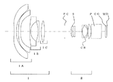
図1に、実施例1の投射用レンズのレンズ構成を示す。 FIG. 1 shows the lens configuration of the projection lens of Example 1.
実施例1の投射用レンズは、拡大側(図の左方)から第1レンズ群I、第2レンズ群IIを配し、開口絞りSは第2レンズ群中の拡大側から1番目と2番目のレンズの間に置かれている。フレアカット絞りFCは第1レンズ群と第2レンズ群の間に配置されている。 In the projection lens of Example 1, the first lens group I and the second lens group II are arranged from the enlargement side (left side in the figure), and the aperture stop S is the first and second from the enlargement side in the second lens group. Is placed between the second lens. The flare cut stop FC is disposed between the first lens group and the second lens group.
投射用レンズと画像表示素子MDの間には、色合成系であるプリズムPとカバーガラスCGが挿入されている。最も拡大側に配された1A群は、弱い負の屈折力を持つガラスレンズと2枚のプラスチックの非球面レンズで構成されている。 Between the projection lens and the image display element MD, a prism P that is a color composition system and a cover glass CG are inserted. The 1A group arranged on the most magnified side includes a glass lens having a weak negative refractive power and two plastic aspherical lenses.
1B群は、縮小側に大きな曲率を持つ負レンズ、拡大側に大きな曲率を持つ負レンズの2枚のレンズから構成されており、1C群は、1枚の正レンズからなっている。 The 1B group is composed of two lenses, a negative lens having a large curvature on the reduction side and a negative lens having a large curvature on the enlargement side, and the 1C group is composed of one positive lens.
第2レンズ群は、拡大側に大きな曲率を持つ正レンズ、両面が非球面であるレンズ、負の屈折力を持つレンズと両面が凸のレンズとメニスカス形状の負レンズの3枚のレンズが張り合わされた接合レンズ、縮小側に大きな曲率を持つ正レンズが配置されている。 The second lens group consists of three lenses: a positive lens with a large curvature on the magnifying side, an aspheric lens on both sides, a lens with negative refractive power, a convex lens on both sides, and a meniscus negative lens. A positive lens having a large curvature is arranged on the reduction side.
フォーカシングは1B群と1C群を移動して行っているが、投射用レンズがスクリーンに近づくと、1B群と1C群は間隔を拡げつつ、共に縮小側に移動する。 Focusing is performed by moving the 1B group and the 1C group, but when the projection lens approaches the screen, the 1B group and the 1C group both move toward the reduction side while increasing the interval.
投射距離が1210mm、980mm、635mmの3つの形態における移動群の位置を「可変データ」として実施例1に代表的に示す。 The position of the moving group in three forms with projection distances of 1210 mm, 980 mm, and 635 mm is representatively shown in Example 1 as “variable data”.
各種データは、投射距離が980mmの状態を代表して示す。また、非球面は面番号に「*」印を付して表す。 Various data are representatively shown in a state where the projection distance is 980 mm. An aspherical surface is represented by adding “*” to the surface number.
「実施例1」
単位 mm
面番号 R D Nd νd 有効径
物面 ∞ (980.000)
1 70.949 3.000 1.51680 64.2 64.141
2 63.500 16.000 59.151
3* -73.697 5.613 1.53159 55.7 58.702
4* 133.155 5.004 48.806
5* 574.532 4.856 1.53159 55.7 45.113
6* 204.849 (可変) 35.680
7 215.772 1.700 1.85026 32.3 28.855
8 24.186 16.230 20.726
9 −53.381 2.000 1.79450 45.4 20.660
10 −2309.27 (可変) 21.176
11 73.562 7.493 1.63980 34.6 22.057
12 −96.274 (可変) 22.000
13(FC) ∞ 13.700 12.200
14 26.173 3.090 1.84666 23.8 11.696
15 61.343 1.359 11.372
16(絞り) ∞ 3.435 11.291
17* −38.807 3.000 1.53159 55.7 11.003
18* −48.706 15.680 10.692
19 153.262 1.200 1.84666 23.8 10.800
20 21.806 11.295 1.49700 81.6 11.153
21 −15.795 1.228 1.85026 32.3 11.939
22 −27.041 0.300 13.283
23 82.048 7.524 1.49700 81.6 14.866
24 −28.673 1.500 15.112
25 ∞ 23.000 1.51680 64.2 14.479
26 ∞ 9.600 12.835
27 ∞ 2.500 1.51680 64.2 11.789
28 ∞ 1.000 11.611
像面 ∞ 11.500 。
"Example 1"
Unit mm
Surface number RD Nd νd Effective diameter object surface ∞ (980.000)
1 70.949 3.000 1.51680 64.2 64.141
2 63.500 16.000 59.151
3 * -73.697 5.613 1.53159 55.7 58.702
4 * 133.155 5.004 48.806
5 * 574.532 4.856 1.53159 55.7 45.113
6 * 204.849 (variable) 35.680
7 215.772 1.700 1.85026 32.3 28.855
8 24.186 16.230 20.726
9 −53.381 2.000 1.79450 45.4 20.660
10 −2309.27 (variable) 21.176
11 73.562 7.493 1.63980 34.6 22.057
12 −96.274 (variable) 22.000
13 (FC) ∞ 13.700 12.200
14 26.173 3.090 1.84666 23.8 11.696
15 61.343 1.359 11.372
16 (Aperture) ∞ 3.435 11.291
17 * −38.807 3.000 1.53159 55.7 11.003
18 * −48.706 15.680 10.692
19 153.262 1.200 1.84666 23.8 10.800
20 21.806 11.295 1.49700 81.6 11.153
21 −15.795 1.228 1.85026 32.3 11.939
22 −27.041 0.300 13.283
23 82.048 7.524 1.49700 81.6 14.866
24 −28.673 1.500 15.112
25 ∞ 23.000 1.51680 64.2 14.479
26 ∞ 9.600 12.835
27 ∞ 2.500 1.51680 64.2 11.789
28 ∞ 1.000 11.611
Image plane ∞ 11.500.
投射距離 1210.000 980.000 635.000
D6 20.964 21.043 21.279
D10 2.453 2.519 2.713
D12 45.876 45.730 45.301 。
Projection distance 1210.000 980.000 635.000
D6 20.964 21.043 21.279
D10 2.453 2.519 2.713
D12 45.876 45.730 45.301.
「非球面データ」
第3面
K=−25.19452、
A3=−2.763504×10⁻⁵、A4=1.046774×10⁻⁵、
A5=−3.650166×10⁻⁸、A6=−4.483305×10⁻⁹、
A7=−6.174553×10⁻¹³、A8=1.268553×10⁻¹²、
A9=1.210906×10⁻¹⁵、A10=−6.281637×10⁻¹⁷、
A11=4.471289×10⁻²⁰、A12=−5.053108×10⁻²⁰、
A13=−4.337784×10⁻²³、A14=1.278649×10⁻²³、
A15=−7.431275×10⁻²⁷、A16=−1.115781×10⁻²⁷、
A17=9.367322×10⁻³¹、A18=1.041467×10⁻³²、
A19=3.048251×10⁻³⁴、A20=1.166872×10⁻³⁵ 。
"Aspherical data"
Third surface K = −25.19452,
A3 = −2.763504 × 10 −5 , A4 = 1.046774 × 10 −5 ,
A5 = −3.650166 × 10 −8 , A6 = −4.483305 × 10 −9 ,
A7 = −6.174553 × 10 −13 , A8 = 1.268553 × 10 −12 ,
A9 = 1.210906 × 10 −15 , A10 = −6.281637 × 10 −17 ,
A11 = 4.471289 × 10 −20 , A12 = −5.053108 × 10 −20 ,
A13 = −4.3337784 × 10 −23 , A14 = 1.278649 × 10 −23 ,
A15 = −7.431275 × 10 −27 , A16 = −1.115781 × 10 −27 ,
A17 = 9.367322 × 10 −31 , A18 = 1.041467 × 10 −32 ,
A19 = 3.048251 × 10 −34 , A20 = 1.166872 × 10 −35 .
第4面
K=−56.804、
A3=2.164171×10⁻⁶、A4=6.834952×10⁻⁶、
A5=2.334382×10⁻⁸、A6=6.654839×10⁻⁹、
A7=6.50019×10⁻¹²、A8=−1.862264×10⁻¹¹、
A9=−1.801516×10⁻¹⁵、A10=1.544124×10⁻¹⁴、
A11=−7.343028×10⁻¹⁹、A12=−5.960511×10⁻¹⁸、
A13=1.056378×10⁻²²、A14=9.64749×10⁻²²、
A15=1.182647×10⁻²⁵、A16=−2.477929×10⁻²⁶、
A17=3.470383×10⁻²⁹、A18=1.861251×10⁻³⁰、
A19=−1.529579×10⁻³²、A20=−2.01992×10⁻³³ 。
4th surface K = -56.804,
A3 = 2.164171 × 10 −6 , A4 = 6.834952 × 10 −6 ,
A5 = 2.334382 × 10 −8 , A6 = 6.654839 × 10 −9 ,
A7 = 6.50019 × 10 −12 , A8 = −1.862264 × 10 −11 ,
A9 = -1.801516 × 10 −15 , A10 = 1.544124 × 10 −14 ,
A11 = −7.343028 × 10 −19 , A12 = −5.960511 × 10 −18 ,
A13 = 1.056378 × 10 −22 , A14 = 9.664749 × 10 −22 ,
A15 = 1.182647 × 10 −25 , A16 = −2.477929 × 10 −26 ,
A17 = 3.470383 × 10 −29 , A18 = 1.861251 × 10 −30 ,
A19 = −1.529579 × 10 −32 , A20 = −2.01992 × 10 −33 .
第5面
K=38.8、
A3=0、A4=4.492137×10⁻⁶、
A5=0、A6=3.117237×10⁻¹⁰、
A7=0、A8=−9.082539×10⁻¹⁴、
A9=0、A10=−1.843702×10⁻¹⁷、
A11=0、A12=2.534436×10⁻²¹、
A13=0、A14=−7.943081×10⁻²⁵、
A15=0、A16=−1.383505×10⁻²⁷、
A17=0、A18=−2.101501×10⁻³¹、
A19=0、A20=4.09991×10⁻³⁴ 。
5th surface K = 38.8,
A3 = 0, A4 = 4.492137 × 10 −6 ,
A5 = 0, A6 = 3.117237 × 10 −10 ,
A7 = 0, A8 = −9.082539 × 10 −14 ,
A9 = 0, A10 = -1.843702 × 10 -17,
A11 = 0, A12 = 2.534436 × 10 −21 ,
A13 = 0, A14 = −7.943081 × 10 −25 ,
A15 = 0, A16 = −1.383505 × 10 −27 ,
A17 = 0, A18 = −2.101501 × 10 −31 ,
A19 = 0, A20 = 4.09991 × 10 −34 .
第6面
K=12.8052、
A3=0、A4=1.166335×10⁻⁵、
A5=0、A6=−4.114748×10⁻⁹、
A7=0、A8=2.194497×10⁻¹²、
A9=0、A10=1.12748×10⁻¹⁵、
A11=0、A12=−1.675317×10⁻¹⁹、
A13=0、A14=−6.202467×10⁻²²、
A15=0、A16=−3.867869×10⁻²⁵、
A17=0、A18=1.208147×10⁻²⁹、
A19=0、A20=2.905148×10⁻³¹ 。
6th surface K = 12.8052,
A3 = 0, A4 = 1.166335 × 10 −5 ,
A5 = 0, A6 = −4.114748 × 10 −9 ,
A7 = 0, A8 = 2.194497 × 10 −12 ,
A9 = 0, A10 = 1.12748 × 10 −15 ,
A11 = 0, A12 = −1.675317 × 10 −19 ,
A13 = 0, A14 = −6.202467 × 10⁻²² ,
A15 = 0, A16 = -3.867869 × 10 -25,
A17 = 0, A18 = 1.208147 × 10 −29 ,
A19 = 0, A20 = 2.905148 × 10 −31 .
第17面
K=−6.794828、
A3=0、A4=6.07159×10⁻⁵、
A5=0、A6=6.840635×10⁻⁸、
A7=0、A8=−5.745192×10⁻¹⁰、
A9=0、A10=−6.969458×10⁻¹²、
A11=0、A12=1.063863×10⁻¹³、
A13=0、A14=−5.983387×10⁻¹⁶、
A15=0、A16=1.336227×10⁻¹⁸ 。
17th surface K = −6.794828,
A3 = 0, A4 = 6.07159 × 10 −5 ,
A5 = 0, A6 = 6.840635 × 10 −8 ,
A7 = 0, A8 = −5.745192 × 10 −10 ,
A9 = 0, A10 = −6.969458 × 10 −12 ,
A11 = 0, A12 = 1.063863 × 10 −13 ,
A13 = 0, A14 = −5.983387 × 10 −16 ,
A15 = 0, A16 = 1.362227 × 10 −18 .
第18面
K=6.017857、
A3=0、A4=9.081342×10⁻⁵、
A5=0、A6=2.801313×10⁻⁷、
A7=0、A8=−3.854062×10⁻⁹、
A9=0、A10=2.711223×10⁻¹¹、
A11=0、A12=−2.073776×10⁻¹⁴、
A13=0、A14=−9.097928×10⁻¹⁶、
A15=0、A16=3.912393×10⁻¹⁸ 。
18th side K = 6.017857,
A3 = 0, A4 = 9.081342 × 10 −5 ,
A5 = 0, A6 = 2.801313 × 10 −7 ,
A7 = 0, A8 = −3.854062 × 10 −9 ,
A9 = 0, A10 = 2.711223 × 10 −11 ,
A11 = 0, A12 = −2.073776 × 10 −14 ,
A13 = 0, A14 = −9.097928 × 10 −16 ,
A15 = 0, A16 = 3.912393 × 10 −18 .
「各種データ」
焦点距離 :6.795
Fナンバー:1.80
半画角 :59.0°
像高 :11.5
BF :28.949
レンズ全長:221.949
「条件式のパラメータの値」
(1)Bf/f=4.260
(2)|f1/f|=2.995
(3)f2/f=5.930
(4)ω=59°
(5)f1B/f1=0.929
(6)(NCBL1+NCBL3)/2−NCBL2=0.351
(7)νCBL2 −(νCBL1+νCBL3)/2=53.57
(8)θgF−(0.6438−0.001682ν)=0.0375
(9)|fP/f2|=9.962
(10)FNO=1.8 。
"Various data"
Focal length: 6.795
F number: 1.80
Half angle of view: 59.0 °
Image height: 11.5
BF: 28.949
Total lens length: 221.949
"Parameter values for conditional expressions"
(1) Bf / f = 4.260
(2) | f1 / f | = 2.995
(3) f2 / f = 5.930
(4) ω = 59 °
(5) f1B / f1 = 0.929
(6) (N CBL1 + N CBL3 ) / 2−N CBL2 = 0.351
(7) ν CBL2 − (ν CBL1 + ν CBL3 ) /2=53.57
(8) θ gF − (0.6438−0.001682ν) = 0.0375
(9) | f P /f2|=9.962
(10) F NO = 1.8.
条件(4)の「ω」は半画角、条件(10)の「FNO」はFナンバーで示す。 “Ω” in condition (4) is a half angle of view, and “F NO ” in condition (10) is an F number.
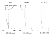
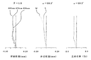
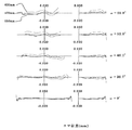
実施例1の投射用レンズを物体距離:980mmにして、縮小側を評価した球面収差、非点収差、歪曲収差の図を図2に、コマ収差の図を図3に示す。 FIG. 2 shows a diagram of spherical aberration, astigmatism, and distortion aberration, and FIG. 3 shows a coma aberration when the projection lens of Example 1 is set to an object distance of 980 mm and the reduction side is evaluated.
各収差図は、550nmの波長を持つ緑色光の収差を示すが、球面収差図、コマ収差図には赤、青の光を代表して波長:620nmと470nmの収差も表示している。非点収差図におけるSはサジタル像面、Mはメリディオナル像面の収差を示す。 Each aberration diagram shows the aberration of green light having a wavelength of 550 nm, but the spherical aberration diagram and coma aberration diagram also show aberrations at wavelengths of 620 nm and 470 nm, representing red and blue light. In the astigmatism diagram, S represents the sagittal image surface, and M represents the aberration of the meridional image surface.
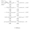
物体距離:1210mmにしたときの球面収差、非点収差、歪曲収差の図を図4に、コマ収差の図を図5に、物体距離:635mmにしたときの球面収差、非点収差、歪曲収差の図を図6に、コマ収差の図を図7に示す。 FIG. 4 is a diagram of spherical aberration, astigmatism and distortion when the object distance is 1210 mm, FIG. 5 is a diagram of coma aberration, and spherical aberration, astigmatism and distortion when the object distance is 635 mm. FIG. 6 shows a diagram of coma and FIG. 7 shows a diagram of coma aberration.
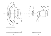
図8に、実施例2の投射用レンズのレンズ構成を示す。 FIG. 8 shows the lens configuration of the projection lens of Example 2.
最も拡大側に配された1A群は2枚のプラスチック製の非球面レンズのみで構成されている。プラスチックはガラスに比べて柔らかく、キズがつきやすいが、ガラス等の透明保護部材をレンズの前面に取り付けることでキズ等を防止することができる。 The 1A group arranged on the most enlarged side is composed of only two plastic aspherical lenses. Plastic is softer than glass and is easily scratched. However, scratches and the like can be prevented by attaching a transparent protective member such as glass to the front surface of the lens.
フォーカシングは実施例1と同様に1B群と1C群を移動して行っている。
「実施例2」
単位 mm
面番号 R D Nd νd 有効径
物面 ∞ (980.000)
1* -76.220 5.100 1.53159 55.7 59.000
2* 109.700 4.840 48.794
3* 890.110 4.600 1.53159 55.7 45.840
4* 224.889 (可変) 35.900
5 200.012 1.700 1.83400 37.3 30.538
6 24.542 16.890 21.409
7 −58.872 2.350 1.78590 43.9 21.320
8 −3753.190 (可変) 21.575
9 85.910 7.340 1.62004 36.3 22.122
10 −100.774 (可変) 22.000
11(FC) ∞ 13.700 12.200
12 27.083 2.860 1.84666 23.8 11.165
13 62.866 1.240 10.836
14(絞り) ∞ 3.317 10.750
15* −37.704 2.810 1.53159 55.7 10.540
16* −44.886 15.500 10.330
17 116.989 1.200 1.84666 23.8 10.800
18 21.877 11.160 1.49700 81.6 11.120
19 −15.844 1.200 1.85026 32.3 11.880
20 −27.765 0.300 13.200
21 87.513 7.140 1.52855 77.0 14.690
22 −29.606 0.300 14.932
23 ∞ 23.000 1.51680 64.2 14.459
24 ∞ 9.400 12.812
25 ∞ 2.500 1.51680 64.2 11.788
26 ∞ 1.000 11.609
像面 ∞ 11.500 。
Focusing is performed by moving the 1B group and the 1C group as in the first embodiment.
"Example 2"
Unit mm
Surface number RD Nd νd Effective diameter object surface ∞ (980.000)
1 * -76.220 5.100 1.53159 55.7 59.000
2 * 109.700 4.840 48.794
3 * 890.110 4.600 1.53159 55.7 45.840
4 * 224.889 (variable) 35.900
5 200.012 1.700 1.83400 37.3 30.538
6 24.542 16.890 21.409
7 −58.872 2.350 1.78590 43.9 21.320
8 -3753.190 (variable) 21.575
9 85.910 7.340 1.62004 36.3 22.122
10 −100.774 (variable) 22.000
11 (FC) ∞ 13.700 12.200
12 27.083 2.860 1.84666 23.8 11.165
13 62.866 1.240 10.836
14 (Aperture) ∞ 3.317 10.750
15 * −37.704 2.810 1.53159 55.7 10.540
16 * −44.886 15.500 10.330
17 116.989 1.200 1.84666 23.8 10.800
18 21.877 11.160 1.49700 81.6 11.120
19 −15.844 1.200 1.85026 32.3 11.880
20 −27.765 0.300 13.200
21 87.513 7.140 1.52855 77.0 14.690
22 −29.606 0.300 14.932
23 ∞ 23.000 1.51680 64.2 14.459
24 ∞ 9.400 12.812
25 ∞ 2.500 1.51680 64.2 11.788
26 ∞ 1.000 11.609
Image plane ∞ 11.500.
投射距離 1093.000 980.000 754.000
D4 20.124 20.162 20.270
D8 5.080 5.085 5.200
D10 45.549 45.505 45.283 。
Projection distance 1093.000 980.000 754.000
D4 20.124 20.162 20.270
D8 5.080 5.085 5.200
D10 45.549 45.505 45.283.
「非球面データ」
第1面
K=−26.07853、
A3=−2.14294×10⁻⁵、A4=1.050306×10⁻⁵、
A5=−3.770807×10⁻⁸、A6=−4.505441×10⁻⁹、
A7=−8.201876×10⁻¹³、A8=1.26776×10⁻¹²、
A9=1.23001×10⁻¹⁵、A10=−6.226667×10⁻¹⁷、
A11=5.365016×10⁻²⁰、A12=−5.047198×10⁻²⁰、
A13=−4.333113×10⁻²³、A14=1.279351×10⁻²³、
A15=−7.555979×10⁻²⁷、A16=−1.120734×10⁻²⁷、
A17=9.13163×10⁻³¹、A18=9.645205×10⁻³³、
A19=2.929262×10⁻³⁴、A20=1.113581×10⁻³⁵ 。
"Aspherical data"
First side K = -26.07853,
A3 = −2.14294 × 10 −5 , A4 = 1.050306 × 10 −5 ,
A5 = −3.770807 × 10 −8 , A6 = −4.505441 × 10 −9 ,
A7 = −8.201876 × 10 −13 , A8 = 1.26776 × 10 −12 ,
A9 = 1.300301 × 10 −15 , A10 = −6.226667 × 10 −17 ,
A11 = 5.365016 × 10 −20 , A12 = −5.047198 × 10 −20 ,
A13 = −4.333113 × 10 −23 , A14 = 1.279351 × 10 −23 ,
A15 = −7.555979 × 10 −27 , A16 = −1.120734 × 10 −27 ,
A17 = 9.13163 × 10 −31 , A18 = 9.645205 × 10 −33 ,
A19 = 2.929262 × 10 −34 , A20 = 1.113581 × 10 −35 .
第2面
K=−38.44171、
A3=3.023057×10⁻⁶、A4=6.820663×10⁻⁶、
A5=2.313507×10⁻⁸、A6=6.651944×10⁻⁹、
A7=6.442439×10⁻¹²、A8=−1.862223×10⁻¹¹、
A9=−1.796082×10⁻¹⁵、A10=1.544131×10⁻¹⁴、
A11=−7.344714×10⁻¹⁹、A12=−5.960585×10⁻¹⁸、
A13=1.05212×10⁻²²、A14=9.646135×10⁻²²、
A15=1.195266×10⁻²⁵、A16=−2.477398×10⁻²⁶、
A17=3.474931×10⁻²⁹、A18=1.873239×10⁻³⁰、
A19=−1.521526×10⁻³²、A20=−2.021858×10⁻³³ 。
Second side K = −38.44171,
A3 = 3.023057 × 10 −6 , A4 = 6.820663 × 10 −6 ,
A5 = 2.313507 × 10 −8 , A6 = 6.651944 × 10 −9 ,
A7 = 6.442439 × 10 −12 , A8 = −1.862223 × 10 −11 ,
A9 = −1.796082 × 10 −15 , A10 = 1.544131 × 10 −14 ,
A11 = −7.344714 × 10 −19 , A12 = −5.960585 × 10 −18 ,
A13 = 1.05212 × 10 −22 , A14 = 9.646135 × 10 −22 ,
A15 = 1.195266 × 10 −25 , A16 = −2.477398 × 10 −26 ,
A17 = 3.4474931 × 10 −29 , A18 = 1.873239 × 10 −30 ,
A19 = −1.521526 × 10 −32 , A20 = −2.021858 × 10 −33 .
第3面
K=38.8、
A3=0、A4=4.475525×10⁻⁶、
A5=0、A6=2.922541×10⁻¹⁰、
A7=0、A8=−9.53755×10⁻¹⁴、
A9=0、A10=−1.784177×10⁻¹⁷、
A11=0、A12=3.540188×10⁻²¹、
A13=0、A14=−4.960417×10⁻²⁵、
A15=0、A16=−1.197276×10⁻²⁷、
A17=0、A18=−8.369469×10⁻³²、
A19=0、A20=4.743864×10⁻³⁴ 。
Third side K = 38.8,
A3 = 0, A4 = 4.475525 × 10 −6 ,
A5 = 0, A6 = 2.922541 × 10 −10 ,
A7 = 0, A8 = −9.53755 × 10 −14 ,
A9 = 0, A10 = −1.784177 × 10 −17 ,
A11 = 0, A12 = 3.540188 × 10 −21 ,
A13 = 0, A14 = −4.960417 × 10 −25 ,
A15 = 0, A16 = −1.197276 × 10 −27 ,
A17 = 0, A18 = −8.369469 × 10 −32 ,
A19 = 0, A20 = 4.743864 × 10 −34 .
第4面
K=18.09735、
A3=0、A4=1.20354×10⁻⁵、
A5=0、A6=−4.179427×10⁻⁹、
A7=0、A8=2.224024×10⁻¹²、
A9=0、A10=1.110446×10⁻¹⁵、
A11=0、A12=−1.998072×10⁻¹⁹、
A13=0、A14=−6.414457×10⁻²²、
A15=0、A16=−3.898259×10⁻²⁵、
A17=0、A18=1.477017×10⁻²⁹、
A19=0、A20=2.933931×10⁻³¹ 。
4th surface K = 18.09735,
A3 = 0, A4 = 1.20354 × 10 −5 ,
A5 = 0, A6 = −4.179427 × 10 −9 ,
A7 = 0, A8 = 2.224024 × 10 −12 ,
A9 = 0, A10 = 1.110446 × 10 −15 ,
A11 = 0, A12 = −1.998072 × 10 −19 ,
A13 = 0, A14 = −6.414457 × 10⁻²² ,
A15 = 0, A16 = -3.898259 × 10 -25,
A17 = 0, A18 = 1.477017 × 10 −29 ,
A19 = 0, A20 = 2.933931 × 10 −31 .
第15面
K=−6.960192、
A3=0、A4=6.097244×10⁻⁵、
A5=0、A6=7.585324×10⁻⁸、
A7=0、A8=−5.694485×10⁻¹⁰、
A9=0、A10=−7.585008×10⁻¹²、
A11=0、A12=1.07548×10⁻¹³、
A13=0、A14=−5.717819×10⁻¹⁶、
A15=0、A16=1.22034×10⁻¹⁸ 。
15th surface K = −6.960192,
A3 = 0, A4 = 6.097244 × 10 −5 ,
A5 = 0, A6 = 7.585324 × 10 −8 ,
A7 = 0, A8 = −5.694485 × 10 −10 ,
A9 = 0, A10 = −7.585008 × 10 −12 ,
A11 = 0, A12 = 1.75548 × 10 −13 ,
A13 = 0, A14 = -5.717819 × 10 -16,
A15 = 0, A16 = 1.22034 × 10 −18 .
第16面
K=5.402902、
A3=0、A4=9.189829×10⁻⁵、
A5=0、A6=2.855597×10⁻⁷、
A7=0、A8=−3.965996×10⁻⁹、
A9=0、A10=2.771514×10⁻¹¹、
A11=0、A12=−2.038141×10⁻¹⁴、
A13=0、A14=−9.565189×10⁻¹⁶、
A15=0、A16=4.151416×10⁻¹⁸ 。
16th surface K = 5.402902,
A3 = 0, A4 = 9.189829 × 10 −5 ,
A5 = 0, A6 = 2.855597 × 10 −7 ,
A7 = 0, A8 = −3.965996 × 10 −9 ,
A9 = 0, A10 = 2.71514 × 10 −11 ,
A11 = 0, A12 = −2.038141 × 10 −14 ,
A13 = 0, A14 = -9.565189 × 10 -16,
A15 = 0, A16 = 4.151416 × 10 −18 .
「各種データ」
焦点距離 :6.548
Fナンバー:1.80
半画角 :60.0°
像高 :11.5
BF :27.569
レンズ全長:201.569
「条件式のパラメータの値」
(1)Bf/f=4.210
(2)|f1/f|=3.325
(3)f2/f=5.894
(4)ω=60°
(5)f1B/f1=0.931
(6)(NCBL1+NCBL3)/2−NCBL2=0.351
(7)νCBL2 −(νCBL1+νCBL3)/2=53.57
(8)θgF−(0.6438−0.001682ν)=0.0258
(9)|fP/f2|=13.316
(10)FNO=1.8 。
"Various data"
Focal length: 6.548
F number: 1.80
Half angle of view: 60.0 °
Image height: 11.5
BF: 27.469
Total lens length: 201.567
"Parameter values for conditional expressions"
(1) Bf / f = 4.210
(2) | f1 / f | = 3.325
(3) f2 / f = 5.894
(4) ω = 60 °
(5) f1B / f1 = 0.931
(6) (N CBL1 + N CBL3 ) / 2−N CBL2 = 0.351
(7) ν CBL2 − (ν CBL1 + ν CBL3 ) /2=53.57
(8) θ gF − (0.6438−0.001682ν) = 0.0258
(9) | f P /f2|=13.316
(10) F NO = 1.8.
条件(4)の「ω」は半画角、条件(10)の「FNO」はFナンバーで示す。 “Ω” in condition (4) is a half angle of view, and “F NO ” in condition (10) is an F number.
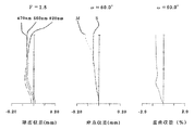
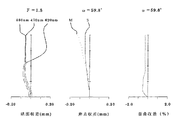
実施例2の投射用レンズを物体距離:980mmにして、縮小側を評価した球面収差、非点収差、歪曲収差の図を図9に、コマ収差の図を図10に示す。 FIG. 9 shows a diagram of spherical aberration, astigmatism, and distortion aberration, and FIG. 10 shows a coma aberration diagram when the projection lens of Example 2 is set to an object distance: 980 mm and the reduction side is evaluated.
図11に、実施例3の投射用レンズのレンズ構成を示す。
「実施例3」
単位 mm
面番号 R D Nd νd 有効径
物面 ∞ (980.000)
1* −75.599 5.130 1.53159 55.7 58.440
2* 121.117 5.040 48.490
3* −69110.000 4.700 1.53159 55.7 45.580
4* 289.850 (可変) 35.680
5 224.219 1.700 1.83400 37.3 29.570
6 24.504 16.620 21.026
7 −52.400 2.955 1.80100 35.0 20.950
8 −4614.250 (可変) 21.465
9 108.715 9.000 1.62588 35.7 22.014
10 −67.547 (可変) 22.000
11(FC) ∞ 13.700 12.200
12 26.514 2.915 1.84666 23.8 11.392
13 58.730 1.780 11.076
14(絞り) ∞ 3.890 10.891
15* −40.730 3.020 1.53159 55.7 10.623
16* −48.440 15.480 10.358
17 96.910 1.200 1.80518 25.5 10.800
18 23.060 10.720 1.45650 90.3 11.091
19 −16.400 1.370 1.84666 23.8 11.834
20 −27.120 0.300 13.068
21 93.340 6.820 1.52855 77.0 14.440
22 −30.290 0.300 14.676
23 ∞ 23.000 1.51680 64.2 14.260
24 ∞ 9.400 12.722
25 ∞ 2.500 1.51680 64.2 11.765
26 ∞ 1.000 11.598
像面 ∞ 11.500 。
FIG. 11 shows the lens configuration of the projection lens of Example 3.
"Example 3"
Unit mm
Surface number RD Nd νd Effective diameter object surface ∞ (980.000)
1 * −75.599 5.130 1.53159 55.7 58.440
2 * 121.117 5.040 48.490
3 * −69110.000 4.700 1.53159 55.7 45.580
4 * 289.850 (variable) 35.680
5 224.219 1.700 1.83400 37.3 29.570
6 24.504 16.620 21.026
7 −52.400 2.955 1.80 100 35.0 20.950
8 −4614.250 (variable) 21.465
9 108.715 9.000 1.62588 35.7 22.014
10 −67.547 (variable) 22.000
11 (FC) ∞ 13.700 12.200
12 26.514 2.915 1.84666 23.8 11.392
13 58.730 1.780 11.076
14 (Aperture) ∞ 3.890 10.891
15 * −40.730 3.020 1.53159 55.7 10.623
16 * −48.440 15.480 10.358
17 96.910 1.200 1.80518 25.5 10.800
18 23.060 10.720 1.45650 90.3 11.091
19 −16.400 1.370 1.84666 23.8 11.834
20 −27.120 0.300 13.068
21 93.340 6.820 1.52855 77.0 14.440
22 −30.290 0.300 14.676
23 ∞ 23.000 1.51680 64.2 14.260
24 ∞ 9.400 12.722
25 ∞ 2.500 1.51680 64.2 11.765
26 ∞ 1.000 11.598
Image plane ∞ 11.500.
投射距離 1093.000 980.000 754.000
D4 20.088 20.124 20.233
D8 2.043 2.070 2.172
D10 45.103 45.040 44.830 。
Projection distance 1093.000 980.000 754.000
D4 20.088 20.124 20.233
D8 2.043 2.070 2.172
D10 45.103 45.040 44.830.
「非球面データ」
第1面
K=−25.64209、
A3=−2.142835×10⁻⁵、A4=1.050107×10⁻⁵、
A5=−3.77351×10⁻⁸、A6=−4.502287×10⁻⁹、
A7=−7.301876×10⁻¹³、A8=1.26901×10⁻¹²、
A9=1.240469×10⁻¹⁵、A10=−6.214056×10⁻¹⁷、
A11=4.923425×10⁻²⁰、A12=−5.054865×10⁻²⁰、
A13=−4.505451×10⁻²³、A14=1.27749×10⁻²³、
A15=−8.133688×10⁻²⁷、A16=−1.130447×10⁻²⁷、
A17=1.654424×10⁻³⁰、A18=1.702769×10⁻³²、
A19=2.957072×10⁻³⁴、A20=9.372945×10−36 。
"Aspherical data"
First side K = −25.64209,
A3 = −2.142835 × 10 −5 , A4 = 1.050107 × 10 −5 ,
A5 = −3.77351 × 10 −8 , A6 = −4.502287 × 10 −9 ,
A7 = −7.301876 × 10 −13 , A8 = 1.26901 × 10 −12 ,
A9 = 1.240469 × 10 −15 , A10 = −6.214056 × 10 −17 ,
A11 = 4.923425 × 10 −20 , A12 = −5.054865 × 10 −20 ,
A13 = −4.505451 × 10 −23 , A14 = 1.27749 × 10 −23 ,
A15 = −8.133688 × 10 −27 , A16 = −1.130447 × 10 −27 ,
A17 = 1.654424 × 10 −30 , A18 = 1.702769 × 10 −32 ,
A19 = 2.957072 × 10 −34 , A20 = 9.372945 × 10 −36 .
第2面
K=−44.36929、
A3=2.207215×10⁻⁶、A4=6.805752×10⁻⁶、
A5=2.302281×10⁻⁸、A6=6.651794×10⁻⁹、
A7=6.436753×10⁻¹²、A8=−1.861324×10⁻¹¹、
A9=−1.73412×10⁻¹⁵、A10=1.544065×10⁻¹⁴、
A11=−7.476027×10⁻¹⁹、A12=−5.960829×10⁻¹⁸、
A13=9.435257×10⁻²³、A14=9.644028×10⁻²²、
A15=1.248983×10⁻²⁵、A16=−2.477161×10⁻²⁶、
A17=3.521942×10⁻²⁹、A18=1.878032×10⁻³⁰、
A19=−1.460855×10⁻³²、A20=−2.03645×10⁻³³ 。
Second side K = -44.36929,
A3 = 2.207215 × 10 −6 , A4 = 6.8805752 × 10 −6 ,
A5 = 2.302281 × 10 −8 , A6 = 6.651794 × 10 −9 ,
A7 = 6.436753 × 10 −12 , A8 = −1.861324 × 10 −11 ,
A9 = −1.73412 × 10 −15 , A10 = 1.544065 × 10 −14 ,
A11 = −7.476027 × 10 −19 , A12 = −5.960829 × 10 −18 ,
A13 = 9.435257 × 10 −23 , A14 = 9.644028 × 10 −22 ,
A15 = 1.248983 × 10 −25 , A16 = −2.477161 × 10 −26 ,
A17 = 3.521942 × 10 −29 , A18 = 1.878032 × 10 −30 ,
A19 = −1.460855 × 10 −32 , A20 = −2.03645 × 10 −33 .
第3面
K=38.8、
A3=0、A4=4.575618×10⁻⁶、
A5=0、A6=3.028185×10⁻¹⁰、
A7=0、A8=−9.364798×10⁻¹⁴、
A9=0、A10=−1.683022×10⁻¹⁷、
A11=0、A12=6.091981×10⁻²¹、
A13=0、A14=−6.367158×10⁻²⁵、
A15=0、A16=−9.000075×10⁻²⁸、
A17=0、A18=−6.012346×10⁻³²、
A19=0、A20=4.097016×10⁻³⁴ 。
Third side K = 38.8,
A3 = 0, A4 = 4.575618 × 10 −6 ,
A5 = 0, A6 = 3.028185 × 10 −10 ,
A7 = 0, A8 = −9.364798 × 10 −14 ,
A9 = 0, A10 = −1.683022 × 10 −17 ,
A11 = 0, A12 = 0.6091981 × 10 −21 ,
A13 = 0, A14 = −6.367158 × 10 −25 ,
A15 = 0, A16 = −9.000075 × 10 −28 ,
A17 = 0, A18 = -6.012346 × 10 -32,
A19 = 0, A20 = 4.097016 × 10 −34 .
第4面
K=24.7016、
A3=0、A4=1.174189×10⁻⁵、
A5=0、A6=−4.076866×10⁻⁹、
A7=0、A8=2.389048×10⁻¹²、
A9=0、A10=1.191704×10⁻¹⁵、
A11=0、A12=−1.786119×10⁻¹⁹、
A13=0、A14=−7.32599×10⁻²²、
A15=0、A16=−3.842542×10⁻²⁵、
A17=0、A18=3.076413×10⁻²⁹、
A19=0、A20=3.180532×10⁻³¹ 。
4th surface K = 24.7016,
A3 = 0, A4 = 1.174189 × 10 −5 ,
A5 = 0, A6 = −4.076866 × 10 −9 ,
A7 = 0, A8 = 2.389048 × 10 −12 ,
A9 = 0, A10 = 1.191704 × 10 −15 ,
A11 = 0, A12 = −1.786119 × 10 −19 ,
A13 = 0, A14 = −7.32599 × 10⁻²² ,
A15 = 0, A16 = -3.842542 × 10 -25,
A17 = 0, A18 = 3.076413 × 10 −29 ,
A19 = 0, A20 = 3.180532 × 10 −31 .
第15面
K=−7.678109、
A3=0、A4=6.208351×10⁻⁵、
A5=0、A6=8.546074×10⁻⁸、
A7=0、A8=−5.344329×10⁻¹⁰、
A9=0、A10=−7.756236×10⁻¹²、
A11=0、A12=1.067252×10⁻¹³、
A13=0、A14=−5.75894×10⁻¹⁶、
A15=0、A16=1.260728×10⁻¹⁸ 。
15th surface K = −7.678109,
A3 = 0, A4 = 6.208351 × 10 −5 ,
A5 = 0, A6 = 8.546074 × 10 −8 ,
A7 = 0, A8 = −5.344329 × 10 −10 ,
A9 = 0, A10 = −7.756236 × 10 −12 ,
A11 = 0, A12 = 1.067252 × 10 −13 ,
A13 = 0, A14 = -5.75894 × 10 -16,
A15 = 0, A16 = 1.260728 × 10 −18 .
第16面
K=5.295017、
A3=0、A4=9.166241×10⁻⁵、
A5=0、A6=3.015101×10⁻⁷、
A7=0、A8=−3.921291×10⁻⁹、
A9=0、A10=2.79351×10⁻¹¹、
A11=0、A12=−2.301897×10⁻¹⁴、
A13=0、A14=−9.850825×10⁻¹⁶、
A15=0、A16=4.361854×10⁻¹⁸ 。
16th surface K = 5.295017,
A3 = 0, A4 = 9.1166241 × 10 −5 ,
A5 = 0, A6 = 3.015101 × 10 −7 ,
A7 = 0, A8 = −3.921291 × 10 −9 ,
A9 = 0, A10 = 2.79351 × 10 −11 ,
A11 = 0, A12 = −2.301897 × 10 −14 ,
A13 = 0, A14 = -9.850825 × 10 -16,
A15 = 0, A16 = 4.361854 × 10 −18 .
「各種データ」
焦点距離 :6.717
Fナンバー:1.80
半画角 :59.3°
像高 :11.500
BF :27.545
レンズ全長:201.119
「条件式のパラメータの値」
(1)Bf/f=4.101
(2)|f1/f|=3.157
(3)f2/f=5.861
(4)ω=59.3°
(5)f1B/f1=0.893
(6)(NCBL1+NCBL3)/2−NCBL2=0.369
(7)νCBL2 −(νCBL1+νCBL3)/2=65.65
(8)θgF−(0.6438−0.001682ν)=0.0258
(9)|fP/f2|=14.178
(10)FNO=1.8 。
"Various data"
Focal length: 6.717
F number: 1.80
Half angle of view: 59.3 °
Image height: 11.500
BF: 27.545
Total lens length: 201.119
"Parameter values for conditional expressions"
(1) Bf / f = 4.101
(2) | f1 / f | = 3.157
(3) f2 / f = 5.861
(4) ω = 59.3 °
(5) f1B / f1 = 0.893
(6) (N CBL1 + N CBL3 ) / 2-N CBL2 = 0.369
(7) ν CBL2 − (ν CBL1 + ν CBL3 ) /2=65.65
(8) θ gF − (0.6438−0.001682ν) = 0.0258
(9) | f P /f2|=14.178
(10) F NO = 1.8.
条件(4)の「ω」は半画角、条件(10)の「FNO」はFナンバーで示す。 “Ω” in condition (4) is a half angle of view, and “F NO ” in condition (10) is an F number.
実施例3の投射用レンズを物体距離:980mmにして、縮小側を評価した球面収差、非点収差、歪曲収差の図を図12に、コマ収差の図を図13に示す。 FIG. 12 shows a diagram of spherical aberration, astigmatism, and distortion aberration, and FIG. 13 shows a coma aberration when the projection lens of Example 3 is set to an object distance of 980 mm and the reduction side is evaluated.
図14に、実施例4の投射用レンズのレンズ構成を示す。 FIG. 14 shows the lens configuration of the projection lens of Example 4.
開口絞りSは第2レンズ群の拡大側近傍に置かれている。 The aperture stop S is placed near the enlargement side of the second lens group.
「実施例4」
単位 mm
面番号 R D Nd νd 有効径
物面 ∞ (818.000)
1* −151.550 5.100 1.53159 55.7 59.000
2* 60.340 7.780 49.208
3* −311.310 4.996 1.53159 55.7 46.203
4* 6160.300 (可変) 34.877
5 208.740 1.700 1.85026 32.3 30.400
6 23.240 15.955 20.130
7 −52.820 5.177 1.79950 42.3 20.053
8 −307.520 (可変) 20.707
9 95.010 8.350 1.62004 36.3 22.100
10 −78.320 (可変) 22.500
11(FC) ∞ 13.600 12.200
12(絞り) ∞ 0.100 10.546
13 24.350 2.720 1.84666 23.8 10.900
14 46.390 4.370 10.681
15* −41.190 2.810 1.53159 55.7 10.428
16* −51.320 13.740 10.130
17 110.750 1.200 1.84666 23.8 10.400
18 20.520 11.150 1.49700 81.6 10.733
19 −15.070 1.200 1.85026 32.3 11.526
20 −26.080 0.300 12.879
21 84.580 7.440 1.49700 81.6 14.700
22 −27.090 4.600 14.712
23 ∞ 21.000 1.51680 64.2 13.762
24 ∞ 4.800 12.300
25 ∞ 2.500 1.51680 64.2 11.788
26 ∞ 1.000 11.614
像面 ∞ 11.500 。
Example 4
Unit mm
Surface number RD Nd νd Effective diameter object surface ∞ (818.000)
1 * −151.550 5.100 1.53159 55.7 59.000
2 * 60.340 7.780 49.208
3 * −311.310 4.996 1.53159 55.7 46.203
4 * 6160.300 (variable) 34.877
5 208.740 1.700 1.85026 32.3 30.400
6 23.240 15.955 20.130
7 −52.820 5.177 1.79950 42.3 20.053
8 −307.520 (variable) 20.707
9 95.010 8.350 1.62004 36.3 22.100
10 −78.320 (variable) 22.500
11 (FC) ∞ 13.600 12.200
12 (Aperture) ∞ 0.100 10.546
13 24.350 2.720 1.84666 23.8 10.900
14 46.390 4.370 10.681
15 * −41.190 2.810 1.53159 55.7 10.428
16 * −51.320 13.740 10.130
17 110.750 1.200 1.84666 23.8 10.400
18 20.520 11.150 1.49700 81.6 10.733
19 −15.070 1.200 1.85026 32.3 11.526
20 −26.080 0.300 12.879
21 84.580 7.440 1.49700 81.6 14.700
22 −27.090 4.600 14.712
23 ∞ 21.000 1.51680 64.2 13.762
24 ∞ 4.800 12.300
25 ∞ 2.500 1.51680 64.2 11.788
26 ∞ 1.000 11.614
Image plane ∞ 11.500.
投射距離 913.000 818.000 627.000
D4 19.536 19.585 19.731
D8 12.945 12.970 13.053
D10 33.832 33.760 33.529 。
Projection distance 913.000 818.000 627.000
D4 19.536 19.585 19.731
D8 12.945 12.970 13.053
D10 33.832 33.760 33.529.
「非球面データ」
第1面
K=−99.01271、
A3=−4.821792×10⁻⁵、A4=1.041683×10⁻⁵、
A5=−3.823635×10⁻⁸、A6=−4.460493×10⁻⁹、
A7=3.181765×10⁻¹³、A8=1.280591×10⁻¹²、
A9=1.237405×10⁻¹⁵、A10=−6.487266×10⁻¹⁷、
A11=−1.330498×10⁻²⁰、A12=−5.161317×10⁻²⁰、
A13=−4.768619×10⁻²³、A14=1.274071×10⁻²³、
A15=−6.10613×10⁻²⁷、A16=−1.031678×10⁻²⁷、
A17=2.40234×10⁻³⁰、A18=3.067746×10⁻³²、
A19=2.252692×10⁻³⁴、A20=2.43471×10−36 。
"Aspherical data"
First side K = −99.01271,
A3 = −4.821792 × 10 −5 , A4 = 1.041683 × 10 −5 ,
A5 = −3.823635 × 10 −8 , A6 = −4.460493 × 10 −9 ,
A7 = 3.181765 × 10 −13 , A8 = 1.280591 × 10 −12 ,
A9 = 1.237405 × 10 −15 , A10 = −6.487266 × 10 −17 ,
A11 = −1.330498 × 10 −20 , A12 = −5.161317 × 10 −20 ,
A13 = −4.768619 × 10 −23 , A14 = 1.274071 × 10 −23 ,
A15 = −6.10613 × 10 −27 , A16 = −1.031678 × 10 −27 ,
A17 = 2.40234 × 10 −30 , A18 = 3.067746 × 10 −32 ,
A19 = 2.252692 × 10 −34 , A20 = 2.43471 × 10 −36 .
第2面
K=−11.26927、
A3=−7.69815×10⁻⁶、A4=6.315489×10⁻⁶、
A5=1.743425×10⁻⁸、A6=6.610438×10⁻⁹、
A7=6.453541×10⁻¹²、A8=−1.861346×10⁻¹¹、
A9=−1.504908×10⁻¹⁵、A10=1.544711×10⁻¹⁴、
A11=−6.221961×10⁻¹⁹、A12=−5.95852×10⁻¹⁸、
A13=1.438247×10⁻²²、A14=9.652203×10⁻²²、
A15=1.264334×10⁻²⁵、A16=−2.476×10⁻²⁶、
A17=3.347273×10⁻²⁹、A18=1.851998×10⁻³⁰、
A19=−1.686779×10⁻³²、A20=−2.066301×10⁻³³ 。
Second side K = −11.26927,
A3 = −7.669815 × 10 −6 , A4 = 6.315489 × 10 −6 ,
A5 = 1.743425 × 10 −8 , A6 = 6.610438 × 10 −9 ,
A7 = 6.453541 × 10 −12 , A8 = −1.861346 × 10 −11 ,
A9 = -1.504908 × 10 −15 , A10 = 1.544711 × 10 −14 ,
A11 = −6.221961 × 10 −19 , A12 = −5.95852 × 10 −18 ,
A13 = 1.438247 × 10 −22 , A14 = 9.652203 × 10 −22 ,
A15 = 1.264334 × 10 −25 , A16 = −2.476 × 10 −26 ,
A17 = 3.347273 × 10 −29 , A18 = 1.851998 × 10 −30 ,
A19 = −1.686779 × 10 −32 , A20 = −2.066301 × 10 −33 .
第3面
K=38.8、
A3=0、A4=6.394423×10⁻⁶、
A5=0、A6=1.334189×10⁻¹⁰、
A7=0、A8=−2.526162×10⁻¹³、
A9=0、A10=−5.418372×10⁻¹⁷、
A11=0、A12=1.524634×10⁻²¹、
A13=0、A14=1.740896×10⁻²⁴、
A15=0、A16=1.445547×10⁻²⁸、
A17=0、A18=5.635382×10⁻³¹、
A19=0、A20=5.128454×10⁻³⁴ 。
Third side K = 38.8,
A3 = 0, A4 = 6.394423 × 10 −6 ,
A5 = 0, A6 = 1.334189 × 10 −10 ,
A7 = 0, A8 = −2.526162 × 10 −13 ,
A9 = 0, A10 = −5.418372 × 10 −17 ,
A11 = 0, A12 = 1.524634 × 10 −21 ,
A13 = 0, A14 = 1.740896 × 10 −24 ,
A15 = 0, A16 = 1.445547 × 10 −28 ,
A17 = 0, A18 = 5.635382 × 10 −31 ,
A19 = 0, A20 = 5.128454 × 10 −34 .
第4面
K=244、
A3=0、A4=1.445313×10⁻⁵、
A5=0、A6=−6.279884×10⁻⁹、
A7=0、A8=4.815306×10⁻¹²、
A9=0、A10=1.945043×10⁻¹⁵、
A11=0、A12=−7.536432×10⁻¹⁹、
A13=0、A14=−1.474809×10⁻²¹、
A15=0、A16=−8.664993×10⁻²⁵、
A17=0、A18=6.338996×10⁻²⁹、
A19=0、A20=7.405543×10⁻³¹ 。
4th surface K = 244,
A3 = 0, A4 = 1.445313 × 10 −5 ,
A5 = 0, A6 = −6.279884 × 10 −9 ,
A7 = 0, A8 = 4.815306 × 10 −12 ,
A9 = 0, A10 = 1.945043 × 10 −15 ,
A11 = 0, A12 = −7.536432 × 10 −19 ,
A13 = 0, A14 = −1.474809 × 10 −21 ,
A15 = 0, A16 = -8.664993 × 10 -25,
A17 = 0, A18 = 6.338996 × 10 −29 ,
A19 = 0, A20 = 7.405543 × 10 −31 .
第15面
K=−12.93189、
A3=0、A4=6.488473×10⁻⁵、
A5=0、A6=1.039483×10⁻⁷、
A7=0、A8=−1.036899×10⁻⁹、
A9=0、A10=−7.191212×10⁻¹²、
A11=0、A12=1.53104×10⁻¹³、
A13=0、A14=−9.229893×10⁻¹⁶、
A15=0、A16=1.958708×10⁻¹⁸ 。
15th surface K = -12.93189,
A3 = 0, A4 = 6.488473 × 10 −5 ,
A5 = 0, A6 = 1.039483 × 10 −7 ,
A7 = 0, A8 = −1.036899 × 10 −9 ,
A9 = 0, A10 = −7.191212 × 10⁻¹² ,
A11 = 0, A12 = 1.53104 × 10 −13 ,
A13 = 0, A14 = -9.229893 × 10 -16,
A15 = 0, A16 = 1.958708 × 10 −18 .
第16面
K=−2.531878、
A3=0、A4=9.576961×10⁻⁵、
A5=0、A6=3.247789×10⁻⁷、
A7=0、A8=−5.489895×10⁻⁹、
A9=0、A10=4.177756×10⁻¹¹、
A11=0、A12=−2.269425×10⁻¹⁴、
A13=0、A14=−1.655107×10⁻¹⁵、
A15=0、A16=7.191509×10⁻¹⁸ 。
16th surface K = −2.531878,
A3 = 0, A4 = 9.576961 × 10 −5 ,
A5 = 0, A6 = 3.247789 × 10 −7 ,
A7 = 0, A8 = −5.489895 × 10 −9 ,
A9 = 0, A10 = 4.177756 × 10 −11 ,
A11 = 0, A12 = −2.269425 × 10 −14 ,
A13 = 0, A14 = −1.655107 × 10 −15 ,
A15 = 0, A16 = 7.191509 × 10 −18 .
「各種データ」
焦点距離 :6.546
Fナンバー:1.80
半画角 :59.8°
像高 :11.500
BF :25.930
レンズ全長:199.933 。
"Various data"
Focal length: 6.546
F number: 1.80
Half angle of view: 59.8 °
Image height: 11.500
BF: 25.930
Total lens length: 199.933.
「条件式のパラメータの値」
(1)Bf/f=3.961
(2)|f1/f|=4.736
(3)f2/f=5.720
(4)ω=59.8°
(5)f1B/f1=0.633
(6)(NCBL1+NCBL3)/2−NCBL2=0.351
(7)νCBL2 −(νCBL1+νCBL3)/2=53.57
(8)θgF−(0.6438−0.001682ν)=0.0375
(9)|fP/f2|=11.601
(10)FNO=1.8 。
"Parameter values for conditional expressions"
(1) Bf / f = 3.961
(2) | f1 / f | = 4.736
(3) f2 / f = 5.720
(4) ω = 59.8 °
(5) f1B / f1 = 0.633
(6) (N CBL1 + N CBL3 ) / 2−N CBL2 = 0.351
(7) ν CBL2 − (ν CBL1 + ν CBL3 ) /2=53.57
(8) θ gF − (0.6438−0.001682ν) = 0.0375
(9) | f P /f2|=11.601
(10) F NO = 1.8.
条件(4)の「ω」は半画角、条件(10)の「FNO」はFナンバーで示す。 “Ω” in condition (4) is a half angle of view, and “F NO ” in condition (10) is an F number.
実施例4の投射用レンズを物体距離:818mmにして、縮小側を評価した球面収差、非点収差、歪曲収差の図を図15に、コマ収差の図を図16に示す。 FIG. 15 shows a diagram of spherical aberration, astigmatism, and distortion aberration, and FIG. 16 shows a diagram of coma aberration when the projection lens of Example 4 is set to an object distance of 818 mm and the reduction side is evaluated.
図17に、実施例5の投射用レンズのレンズ構成を示す。 FIG. 17 shows the lens configuration of the projection lens of Example 5.
「実施例5」
単位 mm
面番号 R D Nd νd 有効径
物面 ∞ (1000.000)
1* −260.148 4.500 1.53159 55.7 55.210
2* 74.823 7.090 47.295
3* −895.060 5.561 1.53159 55.7 42.406
4* −1366.626 (可変) 35.668
5 116.334 1.700 1.85026 32.3 25.266
6 21.224 14.050 18.160
7 −72.617 3.489 1.62299 58.1 17.659
8 90.293 (可変) 17.087
9 151.431 6.223 1.56732 42.8 16.961
10 −66.836 (可変) 16.819
11(FC) ∞ 18.000 13.000
12 32.004 3.176 1.80518 25.5 12.071
13 119.666 1.150 11.802
14(絞り) ∞ 2.290 11.647
15* −34.765 3.276 1.53159 55.7 11.513
16* −44.118 17.586 11.272
17 94.471 1.200 1.84666 23.8 11.300
18 20.660 12.050 1.49700 81.6 11.567
19 −16.670 1.230 1.85026 32.3 12.386
20 −30.628 0.300 13.793
21 73.237 8.220 1.48749 70.7 15.511
22 −29.548 4.000 15.778
23 ∞ 23.000 1.51680 64.2 14.860
24 ∞ 7.000 13.240
25 ∞ 2.500 1.51680 64.2 12.490
26 ∞ 1.000 12.313
像面 ∞ 12.200 。
"Example 5"
Unit mm
Surface number RD Nd νd Effective diameter object surface ∞ (1000.000)
1 * −260.148 4.500 1.53159 55.7 55.210
2 * 74.823 7.090 47.295
3 * −895.060 5.561 1.53159 55.7 42.406
4 * −1366.626 (variable) 35.668
5 116.334 1.700 1.85026 32.3 25.266
6 21.224 14.050 18.160
7 −72.617 3.489 1.62299 58.1 17.659
8 90.293 (variable) 17.087
9 151.431 6.223 1.56732 42.8 16.961
10 −66.836 (variable) 16.819
11 (FC) ∞ 18.000 13.000
12 32.004 3.176 1.80518 25.5 12.071
13 119.666 1.150 11.802
14 (Aperture) ∞ 2.290 11.647
15 * −34.765 3.276 1.53159 55.7 11.513
16 * −44.118 17.586 11.272
17 94.471 1.200 1.84666 23.8 11.300
18 20.660 12.050 1.49700 81.6 11.567
19 −16.670 1.230 1.85026 32.3 12.386
20 −30.628 0.300 13.793
21 73.237 8.220 1.48749 70.7 15.511
22 −29.548 4.000 15.778
23 ∞ 23.000 1.51680 64.2 14.860
24 ∞ 7.000 13.240
25 ∞ 2.500 1.51680 64.2 12.490
26 ∞ 1.000 12.313
Image plane ∞ 12.200.
投射距離 1260.000 1000.000 637.000
D4 16.900 17.005 17.314
D8 17.525 17.589 17.750
D10 14.474 14.304 13.834 。
Projection distance 1260.000 1000.000 637.000
D4 16.900 17.005 17.314
D8 17.525 17.589 17.750
D10 14.474 14.304 13.834.
「非球面データ」
第1面
K=−166.5835、
A3=−3.469328×10⁻⁵、A4=1.014512×10⁻⁵、
A5=−3.338394×10⁻⁸、A6=−4.47005×10⁻⁹、
A7=−1.256664×10⁻¹²、A8=1.261025×10⁻¹²、
A9=1.219598×10⁻¹⁵、A10=−6.107463×10⁻¹⁷、
A11=8.42708×10⁻²⁰、A12=−4.992557×10⁻²⁰、
A13=−3.246769×10⁻²³、A14=1.292911×10⁻²³、
A15=−6.324192×10⁻²⁷、A16=−1.119032×10⁻²⁷、
A17=4.87142×10⁻³¹、A18=2.120428×10⁻³³、
A19=−6.297626×10−36、A20=9.124613×10−36 。
"Aspherical data"
First side K = -166.5835,
A3 = −3.469328 × 10 −5 , A4 = 1.014512 × 10 −5 ,
A5 = −3.3338394 × 10 −8 , A6 = −4.47005 × 10 −9 ,
A7 = −1.256664 × 10 −12 , A8 = 1.261025 × 10 −12 ,
A9 = 1.219598 × 10 −15 , A10 = −6.107463 × 10 −17 ,
A11 = 8.42708 × 10 −20 , A12 = −4.992557 × 10 −20 ,
A13 = −3.246769 × 10 −23 , A14 = 1.292911 × 10 −23 ,
A15 = −6.324192 × 10 −27 , A16 = −1.119032 × 10 −27 ,
A17 = 4.87142 × 10 −31 , A18 = 2.120428 × 10 −33 ,
A19 = −6.297626 × 10 −36 , A20 = 9.124613 × 10 −36 .
第2面
K=−10.11287、
A3=1.782989×10⁻⁶、A4=5.83138×10⁻⁶、
A5=1.105838×10⁻⁸、A6=6.571375×10⁻⁹、
A7=6.370932×10⁻¹²、A8=−1.860725×10⁻¹¹、
A9=−1.280512×10⁻¹⁵、A10=1.544843×10⁻¹⁴、
A11=−5.26963×10⁻¹⁹、A12=−5.956069×10⁻¹⁸、
A13=1.903526×10⁻²²、A14=9.660985×10⁻²²、
A15=1.393773×10⁻²⁵、A16=−2.480433×10⁻²⁶、
A17=2.648205×10⁻²⁹、A18=1.403499×10⁻³⁰、
A19=−1.281192×10⁻³²、A20=−2.084576×10⁻³³ 。
Second side K = −10.11287,
A3 = 1.782989 × 10 −6 , A4 = 5.83138 × 10 −6 ,
A5 = 1.105838 × 10 −8 , A6 = 6.571375 × 10 −9 ,
A7 = 6.370932 × 10 −12 , A8 = −1.860725 × 10 −11 ,
A9 = −1.280512 × 10 −15 , A10 = 1.544843 × 10 −14 ,
A11 = −5.26963 × 10 −19 , A12 = −5.956069 × 10 −18 ,
A13 = 1.903526 × 10 −22 , A14 = 9.660985 × 10 −22 ,
A15 = 1.393773 × 10 −25 , A16 = −2.480433 × 10 −26 ,
A17 = 2.648205 × 10 −29 , A18 = 1.403499 × 10 −30 ,
A19 = −1.281192 × 10 −32 , A20 = −2.084576 × 10 −33 .
第3面
K=400、
A3=0、A4=4.042112×10⁻⁶、
A5=0、A6=1.032643×10⁻⁹、
A7=0、A8=−1.594668×10⁻¹³、
A9=0、A10=−7.631891×10⁻¹⁸、
A11=0、A12=4.148995×10⁻²⁰、
A13=0、A14=2.98573×10⁻²³、
A15=0、A16=1.124841×10⁻²⁶、
A17=0、A18=−1.736013×10⁻³⁰、
A19=0、A20=−7.574587×10⁻³³ 。
Third side K = 400,
A3 = 0, A4 = 4.042112 × 10 −6 ,
A5 = 0, A6 = 1.032643 × 10 −9 ,
A7 = 0, A8 = −1.594668 × 10 −13 ,
A9 = 0, A10 = -7.631891 × 10 -18,
A11 = 0, A12 = 4.148995 × 10 −20 ,
A13 = 0, A14 = 2.85773 × 10 −23 ,
A15 = 0, A16 = 1.124841 × 10 −26 ,
A17 = 0, A18 = −1.736013 × 10 −30 ,
A19 = 0, A20 = −7.574587 × 10 −33 .
第4面
K=55.35923、
A3=0、A4=8.146981×10⁻⁶、
A5=0、A6=−1.307317×10⁻⁹、
A7=0、A8=1.634247×10⁻¹²、
A9=0、A10=8.227149×10⁻¹⁶、
A11=0、A12=−1.700504×10⁻²⁰、
A13=0、A14=−2.310061×10⁻²²、
A15=0、A16=−1.564436×10⁻²⁵、
A17=0、A18=−1.222487×10⁻²⁹、
A19=0、A20=3.247617×10⁻³² 。
4th surface K = 55.35923,
A3 = 0, A4 = 8.146981 × 10 −6 ,
A5 = 0, A6 = −1.307317 × 10 −9 ,
A7 = 0, A8 = 1.634247 × 10 −12 ,
A9 = 0, A10 = 8.227149 × 10 −16 ,
A11 = 0, A12 = −1.700504 × 10 −20 ,
A13 = 0, A14 = −2.310061 × 10 −22 ,
A15 = 0, A16 = −1.564436 × 10 −25 ,
A17 = 0, A18 = −1.222487 × 10 −29 ,
A19 = 0, A20 = 3.247617 × 10 −32 .
第15面
K=−4.294806、
A3=0、A4=5.57151×10⁻⁵、
A5=0、A6=3.574903×10⁻⁸、
A7=0、A8=−4.187437×10⁻¹⁰、
A9=0、A10=−9.71675×10⁻¹²、
A11=0、A12=1.122245×10⁻¹³、
A13=0、A14=−2.14451×10⁻¹⁶、
A15=0、A16=−5.473659×10⁻¹⁸、
A17=0、A18=−1.139223×10⁻²⁰、
A19=0、A20=6.567263×10⁻²³ 。
15th surface K = −4.294806,
A3 = 0, A4 = 5.57151 × 10 −5 ,
A5 = 0, A6 = 3.574903 × 10 −8 ,
A7 = 0, A8 = −4.187437 × 10 −10 ,
A9 = 0, A10 = −9.71675 × 10 −12 ,
A11 = 0, A12 = 1.122245 × 10 −13 ,
A13 = 0, A14 = -2.14451 × 10 -16,
A15 = 0, A16 = -5.473659 × 10 -18,
A17 = 0, A18 = −1.139223 × 10 −20 ,
A19 = 0, A20 = 6.567263 × 10 −23 .
第16面
K=3.920396、
A3=0、A4=7.484172×10⁻⁵、
A5=0、A6=2.346997×10⁻⁷、
A7=0、A8=−4.047804×10⁻⁹、
A9=0、A10=2.850956×10⁻¹¹、
A11=0、A12=−1.014958×10⁻¹⁴、
A13=0、A14=−8.390488×10⁻¹⁶、
A15=0、A16=8.290517×10⁻¹⁹、
A17=0、A18=2.531712×10⁻²⁰、
A19=0、A20=−8.006146×10⁻²³ 。
16th surface K = 3.920396,
A3 = 0, A4 = 7.484172 × 10 −5 ,
A5 = 0, A6 = 2.346997 × 10 −7 ,
A7 = 0, A8 = −4.047804 × 10 −9 ,
A9 = 0, A10 = 2.850956 × 10 −11 ,
A11 = 0, A12 = −1.014958 × 10 −14 ,
A13 = 0, A14 = −8.390488 × 10 −16 ,
A15 = 0, A16 = 8.290517 × 10 −19 ,
A17 = 0, A18 = 2.531712 × 10 −20 ,
A19 = 0, A20 = −8.006146 × 10 −23 .
「各種データ」
焦点距離 :8.235
Fナンバー:1.80
半画角 :55.8°
像高 :12.200
BF :28.759
レンズ全長:188.748 。
"Various data"
Focal length: 8.235
F number: 1.80
Half angle of view: 55.8 °
Image height: 12.200
BF: 28.759
Total lens length: 188.748.
「条件式のパラメータの値」
(1)Bf/f=3.492
(2)|f1/f|=3.333
(3)f2/f=5.000
(4)ω=55.8°
(5)f1B/f1=0.655
(6)(NCBL1+NCBL3)/2−NCBL2=0.351
(7)νCBL2 −(νCBL1+νCBL3)/2=53.57
(8)θgF−(0.6438−0.001682ν)=0.0092
(9)|fP/f2|=8.528
(10)FNO=1.8 。
"Parameter values for conditional expressions"
(1) Bf / f = 3.492
(2) | f1 / f | = 3.333
(3) f2 / f = 5.000
(4) ω = 55.8 °
(5) f1B / f1 = 0.655
(6) (N CBL1 + N CBL3 ) / 2−N CBL2 = 0.351
(7) ν CBL2 − (ν CBL1 + ν CBL3 ) /2=53.57
(8) θ gF − (0.6438−0.001682ν) = 0.0092
(9) | f P /f2|=8.528
(10) F NO = 1.8.
条件(4)の「ω」は半画角、条件(10)の「FNO」はFナンバーで示す。 “Ω” in condition (4) is a half angle of view, and “F NO ” in condition (10) is an F number.
実施例5の投射用レンズを物体距離:1000mmにして、縮小側を評価した球面収差、非点収差、歪曲収差の図を図18に、コマ収差の図を図19に示す。 FIG. 18 shows a diagram of spherical aberration, astigmatism, and distortion when the projection lens of Example 5 is set to an object distance of 1000 mm, and the reduction side is evaluated, and FIG. 19 shows a diagram of coma aberration.
図20に、実施例6の投射用レンズのレンズ構成を示す。 FIG. 20 shows the lens configuration of the projection lens of Example 6.
「実施例6」
単位 mm
面番号 R D Nd νd 有効径
物面 ∞ (1000.000)
1* −305.502 4.750 1.53159 55.7 55.706
2* 74.530 7.100 47.731
3* −906.670 5.500 1.53159 55.7 42.596
4* −1683.610 (可変) 35.955
5 133.070 1.700 1.85026 32.3 25.395
6 22.167 14.563 18.484
7 −75.679 3.500 1.62299 58.1 17.652
8 94.042 (可変) 16.987
9 165.176 5.706 1.62004 36.3 16.376
10 −73.002 (可変) 16.188
11(FC) ∞ 18.000 12.000
12 29.955 3.950 1.78472 25.7 11.805
13 93.441 2.510 11.406
14(絞り) ∞ 1.170 11.000
15* −38.217 3.680 1.53159 55.7 10.961
16* −49.658 15.038 10.760
17 148.523 1.834 1.80518 25.5 10.300
18 21.004 12.710 1.49700 81.6 11.801
19 −16.162 1.690 1.85026 32.3 11.679
20 −27.873 0.300 14.389
21 76.253 8.656 1.49700 81.6 16.359
22 −30.517 4.000 16.611
23 ∞ 23.000 1.51680 64.2 15.443
24 ∞ 7.000 13.467
25 ∞ 2.500 1.51680 64.2 12.550
26 ∞ 1.000 12.335
像面 ∞ 12.200 。
"Example 6"
Unit mm
Surface number RD Nd νd Effective diameter object surface ∞ (1000.000)
1 * −305.502 4.750 1.53159 55.7 55.706
2 * 74.530 7.100 47.731
3 * −906.670 5.500 1.53159 55.7 42.596
4 * −1683.610 (variable) 35.955
5 133.070 1.700 1.85026 32.3 25.395
6 22.167 14.563 18.484
7 −75.679 3.500 1.62299 58.1 17.652
8 94.042 (variable) 16.987
9 165.176 5.706 1.62004 36.3 16.376
10 −73.002 (variable) 16.188
11 (FC) ∞ 18.000 12.000
12 29.955 3.950 1.78472 25.7 11.805
13 93.441 2.510 11.406
14 (Aperture) ∞ 1.170 11.000
15 * −38.217 3.680 1.53159 55.7 10.961
16 * −49.658 15.038 10.760
17 148.523 1.834 1.80518 25.5 10.300
18 21.004 12.710 1.49700 81.6 11.801
19 −16.162 1.690 1.85026 32.3 11.679
20 −27.873 0.300 14.389
21 76.253 8.656 1.49700 81.6 16.359
22 −30.517 4.000 16.611
23 ∞ 23.000 1.51680 64.2 15.443
24 ∞ 7.000 13.467
25 ∞ 2.500 1.51680 64.2 12.550
26 ∞ 1.000 12.335
Image plane ∞ 12.200.
投射距離 1260.000 1000.000 636.000
D4 17.075 17.186 17.498
D8 17.113 17.176 17.351
D10 14.769 14.595 14.108 。
Projection distance 1260.000 1000.000 636.000
D4 17.075 17.186 17.498
D8 17.113 17.176 17.351
D10 14.769 14.595 14.108.
「非球面データ」
第1面
K=−152.0633、
A3=−3.680714×10⁻⁵、A4=1.011965×10⁻⁵、
A5=−3.35382×10⁻⁸、A6=−4.469892×10⁻⁹、
A7=−1.23709×10⁻¹²、A8=1.261347×10⁻¹²、
A9=1.2223×10⁻¹⁵、A10=−6.109285×10⁻¹⁷、
A11=8.285806×10⁻²⁰、A12=−4.996563×10⁻²⁰、
A13=−3.334438×10⁻²³、A14=1.291255×10⁻²³、
A15=−6.599581×10⁻²⁷、A16=−1.122852×10⁻²⁷、
A17=4.478906×10⁻³¹、A18=2.273311×10⁻³³、
A19=1.245241×10⁻³⁵、A20=9.798952×10−36 。
"Aspherical data"
First side K = -152.0633,
A3 = −3.680714 × 10 −5 , A4 = 1.011965 × 10 −5 ,
A5 = −3.35382 × 10 −8 , A6 = −4.469892 × 10 −9 ,
A7 = −1.23709 × 10 −12 , A8 = 1.261347 × 10 −12 ,
A9 = 1.2223 × 10 −15 , A10 = −6.109285 × 10 −17 ,
A11 = 8.285806 × 10 −20 , A12 = −4.996563 × 10 −20 ,
A13 = −3.334438 × 10 −23 , A14 = 1.291255 × 10 −23 ,
A15 = −6.599581 × 10 −27 , A16 = −1.122852 × 10 −27 ,
A17 = 4.478906 × 10 −31 , A18 = 2.273311 × 10 −33 ,
A19 = 1.245241 × 10 −35 , A20 = 9.7798952 × 10 −36 .
第2面
K=−11.01463、
A3=5.878604×10⁻⁷、A4=5.818462×10⁻⁶、
A5=1.089778×10⁻⁸、A6=6.569253×10⁻⁹、
A7=6.345917×10⁻¹²、A8=−1.860742×10⁻¹¹、
A9=−1.278041×10⁻¹⁵、A10=1.544858×10⁻¹⁴、
A11=−5.221055×10⁻¹⁹、A12=−5.955957×10⁻¹⁸、
A13=1.924553×10⁻²²、A14=9.661293×10⁻²²、
A15=1.405654×10⁻²⁵、A16=−2.479199×10⁻²⁶、
A17=2.643575×10⁻²⁹、A18=1.406136×10⁻³⁰、
A19=−1.290465×10⁻³²、A20=−2.089746×10⁻³³ 。
Second surface K = −11.01463,
A3 = 5.878604 × 10 −7 , A4 = 5.818462 × 10 −6 ,
A5 = 1.089778 × 10 −8 , A6 = 6.569253 × 10 −9 ,
A7 = 6.345917 × 10 −12 , A8 = −1.860742 × 10 −11 ,
A9 = −1.278041 × 10 −15 , A10 = 1.544858 × 10 −14 ,
A11 = −5.221055 × 10 −19 , A12 = −5.955957 × 10 −18 ,
A13 = 1.924553 × 10 −22 , A14 = 9.661293 × 10 −22 ,
A15 = 1.405654 × 10 −25 , A16 = −2.479199 × 10 −26 ,
A17 = 2.643575 × 10 −29 , A18 = 1.406136 × 10 −30 ,
A19 = −1.290465 × 10 −32 , A20 = −2.089746 × 10 −33 .
第3面
K=400、
A3=0、A4=3.921448×10⁻⁶、
A5=0、A6=1.014352×10⁻⁹、
A7=0、A8=−1.597866×10⁻¹³、
A9=0、A10=−5.19901×10⁻¹⁸、
A11=0、A12=4.303596×10⁻²⁰、
A13=0、A14=3.031833×10⁻²³、
A15=0、A16=1.120897×10⁻²⁶、
A17=0、A18=−1.912861×10⁻³⁰、
A19=0、A20=−7.723067×10⁻³³ 。
Third side K = 400,
A3 = 0, A4 = 3.921448 × 10 −6 ,
A5 = 0, A6 = 1.014352 × 10 −9 ,
A7 = 0, A8 = −1.597866 × 10 −13 ,
A9 = 0, A10 = −5.19901 × 10 −18 ,
A11 = 0, A12 = 4.303596 × 10 −20 ,
A13 = 0, A14 = 3.031833 × 10 −23 ,
A15 = 0, A16 = 1.120897 × 10 −26 ,
A17 = 0, A18 = −1.912861 × 10 −30 ,
A19 = 0, A20 = −7.723067 × 10 −33 .
第4面
K=55.35923、
A3=0、A4=7.790939×10⁻⁶、
A5=0、A6=−1.396436×10⁻⁹、
A7=0、A8=1.602802×10⁻¹²、
A9=0、A10=8.026152×10⁻¹⁶、
A11=0、A12=−2.782591×10⁻²⁰、
A13=0、A14=−2.268331×10⁻²²、
A15=0、A16=−1.535319×10⁻²⁵、
A17=0、A18=3.797515×10⁻³⁰、
A19=0、A20=3.398452×10⁻³² 。
4th surface K = 55.35923,
A3 = 0, A4 = 7.790939 × 10 −6 ,
A5 = 0, A6 = −1.396436 × 10 −9 ,
A7 = 0, A8 = 1.602802 × 10 −12 ,
A9 = 0, A10 = 8.026152 × 10 −16 ,
A11 = 0, A12 = -2.782591 × 10 -20,
A13 = 0, A14 = −2.268331 × 10⁻²² ,
A15 = 0, A16 = −1.535319 × 10 −25 ,
A17 = 0, A18 = 3.797515 × 10 −30 ,
A19 = 0, A20 = 3.398452 × 10 −32 .
第15面
K=−4.915088、
A3=0、A4=5.666693×10⁻⁵、
A5=0、A6=3.528618×10⁻⁸、
A7=0、A8=−4.589505×10⁻¹⁰、
A9=0、A10=−9.633134×10⁻¹²、
A11=0、A12=1.135412×10⁻¹³、
A13=0、A14=−2.165092×10⁻¹⁶、
A15=0、A16=−6.492946×10⁻¹⁹、
A17=0、A18=−1.195171×10⁻²⁰、
A19=0、A20=7.286549×10⁻²³ 。
15th surface K = −4.915088,
A3 = 0, A4 = 5.666693 × 10 −5 ,
A5 = 0, A6 = 3.528618 × 10 −8 ,
A7 = 0, A8 = −4.589505 × 10 −10 ,
A9 = 0, A10 = −9.633134 × 10 −12 ,
A11 = 0, A12 = 1.135412 × 10 −13 ,
A13 = 0, A14 = −2.165092 × 10 −16 ,
A15 = 0, A16 = −6.4492946 × 10⁻¹⁹ ,
A17 = 0, A18 = −1.195171 × 10 −20 ,
A19 = 0, A20 = 7.286549 × 10 −23 .
第16面
K=3.724294、
A3=0、A4=7.541233×10⁻⁵、
A5=0、A6=2.35543×10⁻⁷、
A7=0、A8=−4.025805×10⁻⁹、
A9=0、A10=2.825007×10⁻¹¹、
A11=0、A12=−1.342769×10⁻¹⁴、
A13=0、A14=−8.44377×10⁻¹⁶、
A15=0、A16=1.002724×10⁻¹⁸、
A17=0、A18=2.685499×10⁻²⁰、
A19=0、A20=−9.175461×10⁻²³ 。
16th surface K = 3.724294,
A3 = 0, A4 = 7.541233 × 10 −5 ,
A5 = 0, A6 = 2.53543 × 10 −7 ,
A7 = 0, A8 = −4.025805 × 10 −9 ,
A9 = 0, A10 = 2.825007 × 10 −11 ,
A11 = 0, A12 = −1.342769 × 10 −14 ,
A13 = 0, A14 = -8.44377 × 10 -16,
A15 = 0, A16 = 1.002724 × 10 −18 ,
A17 = 0, A18 = 2.685499 × 10 −20 ,
A19 = 0, A20 = −9.175461 × 10 −23 .
「各種データ」
焦点距離 :8.236
Fナンバー:1.80
半画角 :55.7°
像高 :12.200
BF :28.803
レンズ全長:190.117 。
"Various data"
Focal length: 8.236
F number: 1.80
Half angle of view: 55.7 °
Image height: 12.200
BF: 28.803
Total lens length: 190.117.
「条件式のパラメータの値」
(1)Bf/f=3.497
(2)|f1/f|=3.459
(3)f2/f=4.920
(4)ω=55.7°
(5)f1B/f1=0.650
(6)(NCBL1+NCBL3)/2−NCBL2=0.331
(7)νCBL2 −(νCBL1+νCBL3)/2=52.73
(8)θgF−(0.6438−0.001682ν)=0.0375
(9)|fP/f2|=8.669
(10)FNO=1.8 。
"Parameter values for conditional expressions"
(1) Bf / f = 3.497
(2) | f1 / f | = 3.459
(3) f2 / f = 4.920
(4) ω = 55.7 °
(5) f1B / f1 = 0.650
(6) (N CBL1 + N CBL3 ) / 2-N CBL2 = 0.331
(7) ν CBL2 − (ν CBL1 + ν CBL3 ) /2=52.73
(8) θ gF − (0.6438−0.001682ν) = 0.0375
(9) | f P /f2|=8.669
(10) F NO = 1.8.
条件(4)の「ω」は半画角、条件(10)の「FNO」はFナンバーで示す。 “Ω” in condition (4) is a half angle of view, and “F NO ” in condition (10) is an F number.
実施例6の投射用レンズを物体距離:1000mmにして、縮小側を評価した球面収差、非点収差、歪曲収差の図を図21に、コマ収差の図を図22に示す。 FIG. 21 shows a diagram of spherical aberration, astigmatism and distortion, and FIG. 22 shows a coma aberration when the projection lens of Example 6 is set to an object distance of 1000 mm and the reduction side is evaluated.
上に挙げた実施例1〜6の投射用レンズは何れも、拡大側から縮小側に向かって、負の屈折力を持つ第1レンズ群と、正の屈折力を持つ第2レンズ群とを上記順序に配してなり、縮小側にテレセントリックであり、第1レンズ群は、拡大側から縮小側に向かって順に、2枚の両面に非球面を有するレンズを含む1A群、縮小側に大きな曲率を持つ負レンズ、拡大側に大きな曲率を持つ負レンズの2枚のレンズを含む1B群、少なくとも1枚の正レンズを含む1C群からなり、前記第2レンズ群は、拡大側から縮小側に向かって順に、拡大側に大きな曲率を持つ正レンズ、非球面を有するレンズ、3枚のレンズが張り合わされた接合レンズ:CB、縮小側に大きな曲率を持つ正レンズが配置された構成を含んでおり、開口絞りを第2レンズ群の最も拡大側に配されたレンズ近傍に配置し、拡大側の共役点が無限遠の時の空気中におけるバックフォーカス:Bf、全系の焦点距離:f 、第1レンズ群の焦点距離:f1、第2レンズ群の焦点距離:f2、半画角(度):ωが、条件:
(1) 3.0 < Bf/f < 5.0
(2) 2.5 <|f1/f|< 6.0
(3) 4.5 < f2/f < 7.0
(4) 50° < ω
を満足している(請求項1)。
Each of the projection lenses of Examples 1 to 6 described above includes a first lens group having a negative refractive power and a second lens group having a positive refractive power from the enlargement side toward the reduction side. The first lens group is arranged in the above order and is telecentric on the reduction side, and the first lens group includes, in order from the enlargement side to the reduction side, a 1A group including lenses having two aspheric surfaces on both sides, and is large on the reduction side. A negative lens having a curvature, a 1B group including two lenses of a negative lens having a large curvature on the enlargement side, and a 1C group including at least one positive lens, and the second lens group includes a reduction side from the enlargement side In this order, a positive lens having a large curvature on the enlargement side, a lens having an aspherical surface, a cemented lens in which three lenses are bonded together: CB, and a positive lens having a large curvature on the reduction side are arranged. The aperture stop of the second lens group Is also arranged in the vicinity of the lens arranged on the magnifying side, the back focus in the air when the conjugate point on the magnifying side is infinity: Bf, the focal length of the entire system: f, the focal length of the first lens group: f1, Focal length of the second lens group: f2, half angle of view (degree): ω, conditions:
(1) 3.0 <Bf / f <5.0
(2) 2.5 <| f1 / f | <6.0
(3) 4.5 <f2 / f <7.0
(4) 50 ° <ω
(Claim 1).
また、実施例1〜6の投射用レンズは、上記1B群の焦点距離:f1Bが、条件:
(5) 0.5 < f1B/f1 < 1.1
を満足している(請求項2)。
In the projection lenses of Examples 1 to 6, the focal length f1B of the group 1B is as follows:
(5) 0.5 <f1B / f1 <1.1
(Claim 2).
また、実施例1〜6の投射用レンズに配される接合レンズ:CBは、拡大側より順に、負の屈折力を持つレンズ:CBL1、両面が凸のレンズ:CBL2、メニスカス形状の負レンズ:CBL3の3枚のレンズから成っており、
前記3枚のレンズ:CBL1、CBL2、CBL3のd線に対するそれぞれの屈折率:NCBL1、NCBL2、NCBL3、アッベ数:νCBL1、νCBL2、νCBL3、が、条件:
(6) 0.3 <(NCBL1+NCBL3)/2−NCBL2 < 0.5
(7) 35 < νCBL2 −(νCBL1+νCBL3)/2 < 70
を満足している(請求項3)。
In addition, the cemented lens CB arranged in the projection lenses of Examples 1 to 6 includes, in order from the enlargement side, a lens having negative refractive power: CBL1, a lens having both convex surfaces: CBL2, and a meniscus negative lens: It consists of three CBL3 lenses,
The three lenses: CBL1, CBL2, and CBL3 with respect to the d-line, respectively, refractive indexes: N CBL1 , N CBL2 , N CBL3 , Abbe number: ν CBL1 , ν CBL2 , ν CBL3 , are:
(6) 0.3 <(N CBL1 + N CBL3 ) / 2-N CBL2 <0.5
(7) 35 <ν CBL2− (ν CBL1 + ν CBL3 ) / 2 <70
(Claim 3).
また、実施例1〜6の投射用レンズは、接合レンズ:CBの縮小側に配された正レンズのアッベ数:ν、部分分散比:θgFが、条件:
(8) 0 < θgF−(0.6438−0.001682ν) <0.05
を満足している(請求項4)。
In addition, in the projection lenses of Examples 1 to 6, the cemented lens: Abbe number of the positive lens arranged on the reduction side of CB: ν, partial dispersion ratio: θ gF , conditions:
(8) 0 <θ gF − (0.6438−0.001682ν) <0.05
(Claim 4).
また、実施例1〜5の投射用レンズは、第2レンズ群内の非球面を有するレンズがプラスチックで形成され、その焦点距離:fPが、条件:
(9)7.0 <|fP/f2|
を満足している(請求項5)。
In the projection lenses of Examples 1 to 5, a lens having an aspheric surface in the second lens group is formed of plastic, and its focal length: f P is a condition:
(9) 7.0 <| f P / f2 |
(Claim 5).
また、実施例1〜6の投射用レンズは、フォーカシングの際、1B群と1C群が光軸上を移動して行い(請求項6)、拡大側の共役点を遠距離から近距離方向へ移動させてフォーカシングする際、1B群と1C群の間隔は拡がり、共に縮小側に移動している(請求項7)。 In the projection lenses of Examples 1 to 6, the 1B group and the 1C group are moved on the optical axis during focusing (Claim 6), and the conjugate point on the enlargement side is changed from a long distance to a short distance direction. When focusing by moving, the interval between the 1B group and the 1C group is widened, and both are moving to the reduction side (Claim 7).
また、実施例1〜6の投射用レンズは、レンズの明るさを表すFナンバー:FNOが、条件:
(10)1.7 < FNO < 3.0
を満足している(請求項8)。
Moreover, projection lenses of Examples 1 to 6, F-number representing the brightness of the lens: F NO is the condition:
(10) 1.7 < FNO <3.0
(Claim 8).
従って、投射型画像表示装置は上記実施例1〜6の投射用レンズを搭載することで、短い投射距離で明るく、高精細な画像を表示することが可能である(請求項10)。 Therefore, the projection-type image display apparatus can display a bright and high-definition image at a short projection distance by mounting the projection lenses of the first to sixth embodiments.
I 第1レンズ群
II 第2レンズ群
S 開口絞り
FC フレアカット絞り
P プリズム
CG カバーガラス
MD 表示素子
1A 1A群
1B 1B群
1C 1C群
CB 3枚接合レンズ
I First lens group
II Second lens group S Aperture stop
FC Flare cut stop P Prism CG Cover glass MD Display element 1A 1A group
Claims (10)
縮小側にテレセントリックで、
前記第1レンズ群は、拡大側から縮小側に向かって順に、両面に非球面を有する2枚のレンズを含む1A群と、縮小側に大きな曲率を持つ負レンズ、拡大側に大きな曲率を持つ負レンズの2枚の負レンズを含む1B群と、少なくとも1枚の正レンズを含む1C群とからなり、
前記第2レンズ群は、拡大側から縮小側に向かって順に、拡大側に大きな曲率を持つ正レンズ、非球面を有するレンズ、3枚のレンズが張り合わされた接合レンズ:CB、縮小側に大きな曲率を持つ正レンズを配置してなり、
拡大側の共役点が無限遠の時の空気中におけるバックフォーカス:Bf、全系の焦点距離:f、第1レンズ群の焦点距離:f1、第2レンズ群の焦点距離:f2、半画角(度):ωが、条件:
(1) 3.0 < Bf/f < 5.0
(2) 2.5 <|f1/f|< 6.0
(3) 4.5 < f2/f < 7.0
(4) 50° < ω
を満足することを特徴とする投射用レンズ。 The first lens group having a negative refractive power and the second lens group having a positive refractive power are arranged in the above order from the enlargement side to the reduction side, and arranged on the most enlargement side of the second lens group. An aperture stop is placed near the lens,
Telecentric on the reduction side,
The first lens group includes, in order from the enlargement side to the reduction side, a 1A group including two lenses having aspheric surfaces on both sides, a negative lens having a large curvature on the reduction side, and a large curvature on the enlargement side. 1B group including two negative lenses of the negative lens and 1C group including at least one positive lens,
The second lens group includes, in order from the enlargement side to the reduction side, a positive lens having a large curvature on the enlargement side, a lens having an aspheric surface, and a cemented lens in which three lenses are bonded to each other: CB, and large on the reduction side. A positive lens with a curvature,
Back focus in the air when the conjugate point on the enlargement side is infinity: Bf, focal length of the entire system: f, focal length of the first lens group: f1, focal length of the second lens group: f2, half angle of view (Degrees): ω, condition:
(1) 3.0 <Bf / f <5.0
(2) 2.5 <| f1 / f | <6.0
(3) 4.5 <f2 / f <7.0
(4) 50 ° <ω
Projection lens characterized by satisfying
第1レンズ群の1A群に含まれる両面に非球面を有する2枚のレンズがプラスチックレンズで、1B群の2枚の負レンズがガラスレンズであり、
第1レンズ群の焦点距離:f1、1B群の焦点距離:f1Bが、条件:
(5) 0.5 < f1B/f1 < 1.1
を満足することを特徴とする投射用レンズ。 The projection lens according to claim 1,
The two lenses having aspheric surfaces on both surfaces included in the 1A group of the first lens group are plastic lenses, and the two negative lenses of the 1B group are glass lenses,
The focal length of the first lens group: f1, the focal length of the 1B group: f1B is the condition:
(5) 0.5 <f1B / f1 <1.1
Projection lens characterized by satisfying
第2レンズ群の接合レンズ:CBが、拡大側より順に、負の屈折力を持つレンズ:CBL1、両面が凸のレンズ:CBL2、メニスカス形状の負レンズ:CBL3の3枚のレンズからなり、
第2レンズ群の接合レンズ:CBを構成するレンズ:CBL1、CBL2、CBL3のd線に対するそれぞれの屈折率:NCBL1、NCBL2、NCBL3、アッベ数:νCBL1、νCBL2、νCBL3が、条件:
(6) 0.3 <(NCBL1+NCBL3)/2−NCBL2 < 0.5
(7) 35 < νCBL2−(νCBL1+νCBL3)/2 < 70
を満足することを特徴とする投射用レンズ。 The projection lens according to claim 1 or 2,
The cemented lens of the second lens group: CB is composed of three lenses in order from the enlargement side: a lens having negative refractive power: CBL1, a lens having both convex surfaces: CBL2, and a meniscus negative lens: CBL3.
Joint lens of the second lens group : Lenses constituting CB: Refractive indexes of CBL1, CBL2, and CBL3 with respect to the d-line: N CBL1 , N CBL2 , N CBL3 , Abbe numbers: ν CBL1 , ν CBL2 , and ν CBL3 , conditions:
(6) 0.3 <(N CBL1 + N CBL3 ) / 2-N CBL2 <0.5
(7) 35 <ν CBL2− (ν CBL1 + ν CBL3 ) / 2 <70
Projection lens characterized by satisfying
第2レンズ群の接合レンズ:CBの縮小側に配された正レンズの材質のアッベ数:ν、部分分散比:θgFが、条件:
(8) 0 < θgF−(0.6438−0.001682ν) <0.05
を満足することを特徴とする投射用レンズ。 The projection lens according to any one of claims 1 to 3,
The cemented lens of the second lens group: the Abbe number of the positive lens material arranged on the reduction side of the CB: ν, the partial dispersion ratio: θ gF are the conditions:
(8) 0 <θ gF − (0.6438−0.001682ν) <0.05
Projection lens characterized by satisfying
第2レンズ群内の非球面を有するレンズはプラスチックで形成され、その焦点距離:fPが、条件:
(9)7.0 <|fP/f2|
を満足することを特徴とする投射用レンズ。 The projection lens according to any one of claims 1 to 4,
The lens having an aspheric surface in the second lens group is made of plastic, and its focal length: f P is:
(9) 7.0 <| f P / f2 |
Projection lens characterized by satisfying
第1レンズ群の1B群と1C群が光軸上を移動してフォーカシングを行うことを特徴とする投射用レンズ。 In the projection lens according to any one of claims 1 to 5,
A projection lens, wherein the 1B group and the 1C group of the first lens group move on the optical axis to perform focusing.
拡大側の共役点を遠距離から近距離方向へ移動させてフォーカシングする際、1B群と1C群の間隔が拡がりつつ、共に縮小側に移動することを特徴とする投射用レンズ。 The projection lens according to claim 6,
A projection lens, characterized in that when focusing is performed by moving a conjugate point on the enlargement side from a long distance to a short distance direction, the distance between the 1B group and the 1C group is widened and both are moved to the reduction side.
レンズの明るさを表すFナンバー:FNOが、条件:
(10)1.7 < FNO < 3.0
を満足することを特徴とする投射用レンズ。 The projection lens according to any one of claims 1 to 7,
F number indicating the brightness of the lens: FNO is the condition:
(10) 1.7 < FNO <3.0
Projection lens characterized by satisfying
第1レンズ群と第2レンズ群との間にフレアカット絞りを配したことを特徴とする投射用レンズ。 In the projection lens according to any one of claims 1 to 8,
A projection lens, wherein a flare-cut stop is disposed between the first lens group and the second lens group.
Priority Applications (1)
| Application Number | Priority Date | Filing Date | Title |
|---|---|---|---|
| JP2009292966A JP5367557B2 (en) | 2009-12-24 | 2009-12-24 | Projection lens and projection-type image display device |
Applications Claiming Priority (1)
| Application Number | Priority Date | Filing Date | Title |
|---|---|---|---|
| JP2009292966A JP5367557B2 (en) | 2009-12-24 | 2009-12-24 | Projection lens and projection-type image display device |
Publications (2)
| Publication Number | Publication Date |
|---|---|
| JP2011133656A JP2011133656A (en) | 2011-07-07 |
| JP5367557B2 true JP5367557B2 (en) | 2013-12-11 |
Family
ID=44346461
Family Applications (1)
| Application Number | Title | Priority Date | Filing Date |
|---|---|---|---|
| JP2009292966A Active JP5367557B2 (en) | 2009-12-24 | 2009-12-24 | Projection lens and projection-type image display device |
Country Status (1)
| Country | Link |
|---|---|
| JP (1) | JP5367557B2 (en) |
Families Citing this family (5)
| Publication number | Priority date | Publication date | Assignee | Title |
|---|---|---|---|---|
| JP5638482B2 (en) * | 2011-07-29 | 2014-12-10 | 富士フイルム株式会社 | Projection display |
| KR102422126B1 (en) | 2015-06-09 | 2022-07-18 | 한화테크윈 주식회사 | Zoom lens system |
| JP2017167253A (en) * | 2016-03-15 | 2017-09-21 | 日立マクセル株式会社 | Imaging lens system and imaging apparatus |
| CN112684584B (en) * | 2021-01-08 | 2025-04-25 | 中山联合光电科技股份有限公司 | Projection optical system, projection component and projector |
| CN118688941B (en) * | 2024-07-17 | 2025-02-11 | 杭州图谱光电科技有限公司 | A UV narrow spectrum low distortion double telecentric projection lithography lens |
Family Cites Families (7)
| Publication number | Priority date | Publication date | Assignee | Title |
|---|---|---|---|---|
| JP4632724B2 (en) * | 2004-09-07 | 2011-02-16 | オリンパス株式会社 | Zoom lens |
| JP2008249842A (en) * | 2007-03-29 | 2008-10-16 | Sony Corp | Zoom lens and imaging device |
| JP5042708B2 (en) * | 2007-05-21 | 2012-10-03 | 富士フイルム株式会社 | Projection lens and projection display device using the same |
| JP5026929B2 (en) * | 2007-11-07 | 2012-09-19 | リコー光学株式会社 | Projection lens and projection-type image display device |
| JP5189451B2 (en) * | 2008-09-30 | 2013-04-24 | リコー光学株式会社 | Projection lens and projection-type image display device |
| JP2010113193A (en) * | 2008-11-07 | 2010-05-20 | Topcon Corp | Projection lens |
| JP5280831B2 (en) * | 2008-12-24 | 2013-09-04 | 株式会社トプコン | Temperature compensated projection lens |
-
2009
- 2009-12-24 JP JP2009292966A patent/JP5367557B2/en active Active
Also Published As
| Publication number | Publication date |
|---|---|
| JP2011133656A (en) | 2011-07-07 |
Similar Documents
| Publication | Publication Date | Title |
|---|---|---|
| JP4380086B2 (en) | Zoom lens | |
| US8320048B2 (en) | Projection lens and projection-type display apparatus using the lens | |
| JP4232269B2 (en) | Projection optical system | |
| US8213091B2 (en) | Wide-angle projection zoom lens and projection display device | |
| US9195034B2 (en) | Lens for projection and projection-type display apparatus | |
| JP5316968B2 (en) | Projection lens and optical apparatus equipped with the same | |
| JP5189451B2 (en) | Projection lens and projection-type image display device | |
| US9995917B2 (en) | Projection zoom lens and projection type display device | |
| JP5026929B2 (en) | Projection lens and projection-type image display device | |
| JPH09304694A (en) | Projection lens system and projection apparatus including the same | |
| JP5731176B2 (en) | Projection lens and projection-type image display device | |
| JP4750319B2 (en) | Projection zoom lens | |
| JP5865207B2 (en) | Projection zoom lens, projection-type image display device, and imaging device | |
| JP5530308B2 (en) | Projection zoom lens and projection-type image display device | |
| JP5367557B2 (en) | Projection lens and projection-type image display device | |
| JP2015014677A (en) | Projection lens and projection display device | |
| JP4847110B2 (en) | Projection lens and projection-type image display device | |
| JP2011154318A (en) | Lens system and optical equipment with the lens system mounted therein | |
| CN204215094U (en) | Projection optics system and projection type video display device | |
| JP4211373B2 (en) | Projection lens and projector provided with the same | |
| JP4757990B2 (en) | Projection lens | |
| US20140049835A1 (en) | Wide-angle projection lens and projection display device using the same | |
| JP6033719B2 (en) | Projection lens | |
| WO2008015938A1 (en) | Wide-angle lens for projection and projector with the same | |
| JP4673088B2 (en) | Projection lens and projection-type image display device |
Legal Events
| Date | Code | Title | Description |
|---|---|---|---|
| A621 | Written request for application examination |
Free format text: JAPANESE INTERMEDIATE CODE: A621 Effective date: 20120626 |
|
| A977 | Report on retrieval |
Free format text: JAPANESE INTERMEDIATE CODE: A971007 Effective date: 20130612 |
|
| A131 | Notification of reasons for refusal |
Free format text: JAPANESE INTERMEDIATE CODE: A131 Effective date: 20130618 |
|
| A521 | Request for written amendment filed |
Free format text: JAPANESE INTERMEDIATE CODE: A523 Effective date: 20130725 |
|
| TRDD | Decision of grant or rejection written | ||
| A01 | Written decision to grant a patent or to grant a registration (utility model) |
Free format text: JAPANESE INTERMEDIATE CODE: A01 Effective date: 20130820 |
|
| A61 | First payment of annual fees (during grant procedure) |
Free format text: JAPANESE INTERMEDIATE CODE: A61 Effective date: 20130911 |
|
| R150 | Certificate of patent or registration of utility model |
Ref document number: 5367557 Country of ref document: JP Free format text: JAPANESE INTERMEDIATE CODE: R150 Free format text: JAPANESE INTERMEDIATE CODE: R150 |
|
| R250 | Receipt of annual fees |
Free format text: JAPANESE INTERMEDIATE CODE: R250 |
|
| R250 | Receipt of annual fees |
Free format text: JAPANESE INTERMEDIATE CODE: R250 |
|
| R250 | Receipt of annual fees |
Free format text: JAPANESE INTERMEDIATE CODE: R250 |
|
| S111 | Request for change of ownership or part of ownership |
Free format text: JAPANESE INTERMEDIATE CODE: R313111 |
|
| R350 | Written notification of registration of transfer |
Free format text: JAPANESE INTERMEDIATE CODE: R350 |
|
| S111 | Request for change of ownership or part of ownership |
Free format text: JAPANESE INTERMEDIATE CODE: R313111 |
|
| R350 | Written notification of registration of transfer |
Free format text: JAPANESE INTERMEDIATE CODE: R350 |
|
| S111 | Request for change of ownership or part of ownership |
Free format text: JAPANESE INTERMEDIATE CODE: R313111 |
|
| R350 | Written notification of registration of transfer |
Free format text: JAPANESE INTERMEDIATE CODE: R350 |
|
| SG99 | Written request for registration of restore |
Free format text: JAPANESE INTERMEDIATE CODE: R316G99 |
|
| R350 | Written notification of registration of transfer |
Free format text: JAPANESE INTERMEDIATE CODE: R350 |