JP5367552B2 - Image processing apparatus and image processing program - Google Patents
Image processing apparatus and image processing program Download PDFInfo
- Publication number
- JP5367552B2 JP5367552B2 JP2009284317A JP2009284317A JP5367552B2 JP 5367552 B2 JP5367552 B2 JP 5367552B2 JP 2009284317 A JP2009284317 A JP 2009284317A JP 2009284317 A JP2009284317 A JP 2009284317A JP 5367552 B2 JP5367552 B2 JP 5367552B2
- Authority
- JP
- Japan
- Prior art keywords
- bits
- rgb
- value
- format
- image processing
- Prior art date
- Legal status (The legal status is an assumption and is not a legal conclusion. Google has not performed a legal analysis and makes no representation as to the accuracy of the status listed.)
- Expired - Fee Related
Links
Images
Classifications
-
- H—ELECTRICITY
- H04—ELECTRIC COMMUNICATION TECHNIQUE
- H04N—PICTORIAL COMMUNICATION, e.g. TELEVISION
- H04N9/00—Details of colour television systems
- H04N9/64—Circuits for processing colour signals
- H04N9/68—Circuits for processing colour signals for controlling the amplitude of colour signals, e.g. automatic chroma control circuits
-
- H—ELECTRICITY
- H03—ELECTRONIC CIRCUITRY
- H03M—CODING; DECODING; CODE CONVERSION IN GENERAL
- H03M7/00—Conversion of a code where information is represented by a given sequence or number of digits to a code where the same, similar or subset of information is represented by a different sequence or number of digits
- H03M7/14—Conversion to or from non-weighted codes
- H03M7/24—Conversion to or from floating-point codes
Landscapes
- Engineering & Computer Science (AREA)
- Theoretical Computer Science (AREA)
- Multimedia (AREA)
- Signal Processing (AREA)
- Image Generation (AREA)
- Image Processing (AREA)
- Controls And Circuits For Display Device (AREA)
Description
本発明は画像処理装置および画像処理プログラムに関し、特に、画素の色または明度を浮動少数点形式で表現するフォーマットに適用して好適なものである。 The present invention relates to an image processing equipment Contact and image processing program, in particular, it is suitably applied to a format for representing a color or brightness of pixels in the floating point format.
高品質なコンピュータグラフィックス画像を生成するために、HDR(High Dynamic−range Rendering)技術の重要性が増しつつある。このHDRでは、各画素の色に関し、0〜1.0の範囲を超えた広いダイナミックレンジで処理する必要がある。 In order to generate high-quality computer graphics images, the importance of HDR (High Dynamic-range Rendering) technology is increasing. In this HDR, it is necessary to process with a wide dynamic range exceeding the range of 0 to 1.0 with respect to the color of each pixel.
そのため、フレームバッファ内の各画素のRGB各成分の明度を16ビットの浮動小数点形式(指数部5ビット、仮数部11ビット)で表現するフォーマット(R16G16B16A16_FLOAT)が広く使われている。ただし、この方法では、RGB各成分の明度を表現するために3×16ビットが必要になる。このため、透明度を表すアルファ成分を含めると、1ピクセル当たり64ビット分だけ消費し、メモリ容量およびメモリバンド幅が増大する。
Therefore, a format (R16G16B16A16_FLOAT) that expresses the brightness of each RGB component of each pixel in the frame buffer in a 16-bit floating point format (
メモリ容量およびメモリバンド幅を半減させるために、1ピクセル当たり32ビットで表現する方式もいくつか提案されている。例えば、マイクロソフト社のDirectX10ではR9G9B9E5_SHAREDEXPやR11G11B10_FLOATという浮動小数点ベースのフォーマットが定義されている。また、商用ゲーム機のXbox360ではR10G10B10A2_FLOATというフォーマットが用いられている。 In order to halve the memory capacity and the memory bandwidth, several methods of expressing with 32 bits per pixel have been proposed. For example, Microsoft DirectX10 defines floating point base formats such as R9G9B9E5_SHAREDEXP and R11G11B10_FLOAT. Further, Xbox 360 of a commercial game machine uses a format of R10G10B10A2_FLOAT.
また、例えば、特許文献1には、画像を複数の画像ブロックに分解し、各画素の高ダイナミックレンジ値から画像ブロックにおける画素の色情報および輝度情報を分離し、画像ブロックにおける画素の色情報と画像ブロックにおける画素の輝度情報とを互いに独立に圧縮する方法が開示されている。
Further, for example,
しかしながら、R9G9B9E5_SHAREDEXPでは、RGB各成分で指数部が共通であるため、色が飽和する時に極端に精度が低下するという問題があった。 However, in R9G9B9E5_SHAREDEXP, there is a problem that the accuracy is extremely lowered when the color is saturated because the exponent part is common to the RGB components.
また、R11G11B10_FLOATでは、Bチャネルの仮数部が5ビットと少なくマッハバンドが知覚される可能性があるという問題があった。 In addition, R11G11B10_FLOAT has a problem that the mantissa part of the B channel is as small as 5 bits and a Mach band may be perceived.
また、R10G10B10A2_FLOATでは、エンコードおよびデコードの回路規模は少なくてすむものの、指数部が3ビットしか割り当てられていないため、ダイナミックレンジ不足および精度不足をきたし、やはりマッハバンドが知覚される可能性があるという問題があった。 In addition, in R10G10B10A2_FLOAT, although the encoding and decoding circuit scale is small, only 3 bits are allocated to the exponent part, so that the dynamic range is insufficient and the accuracy is insufficient, and the Mach band may be perceived. There was a problem.
また、特許文献1に開示された方法は、様々なフォーマットで表現された画像データの圧縮に関するもので、メモリ容量およびメモリバンド幅を低減するためのフォーマット表現に関するものではない。
The method disclosed in
本発明の目的は、1画素当たりに割り当てられるビット数を低減しつつ、広いダイナミックレンジを確保するとともに、マッハバンドが知覚されないようにすることが可能な画像処理装置および画像処理プログラムを提供することである。 An object of the present invention, while reducing the number of bits allocated per pixel, offers a wide while securing the dynamic range, image processing program and our image processing equipment capable of Mach bands from being perceived It is to be.
本発明の一態様によれば、画素の色または明度が整数ビット長で表現される仮数部と非整数ビット長で表現される指数部を含む第1のフォーマットの浮動少数点形式で表現されたデータを記憶する記憶部と、前記データの処理を行う画像処理部とを備えることを特徴とする画像処理装置を提供する。 According to one aspect of the present invention, the color or brightness of a pixel is expressed in a floating-point format of a first format including a mantissa part represented by an integer bit length and an exponent part represented by a non-integer bit length. Provided is an image processing apparatus comprising a storage unit for storing data and an image processing unit for processing the data.
本発明の一態様によれば、画素の色または明度が整数ビット長で表現される仮数部と非整数ビット長で表現される指数部を含む浮動少数点形式のフォーマットで表現された画像データを記憶させるステップと、前記画像データを処理するステップとをコンピュータに実行させることを特徴とする画像処理プログラムを提供する。 According to one aspect of the present invention, image data represented in a floating-point format including a mantissa part in which the color or brightness of a pixel is represented by an integer bit length and an exponent part represented by a non-integer bit length is obtained. An image processing program is provided that causes a computer to execute a step of storing and a step of processing the image data.
本発明によれば、1画素当たりに割り当てられるビット数を低減しつつ、広いダイナミックレンジを確保するとともに、マッハバンドが知覚されないようにすることが可能となる。 According to the present invention, it is possible to secure a wide dynamic range and reduce the perception of a Mach band while reducing the number of bits allocated per pixel.
以下、本発明の実施形態に係る画像データの表現に用いられるフォーマットおよび画像処理装置について図面を参照しながら説明する。なお、以下の説明では、画素の色がRGBの3要素で表現される場合を例にとって説明するが、本発明は、画素の色がRGBの3要素で表現される場合に限定されることなく、例えば、画素の色がYUVの3要素で表現される場合などに適用してもよい。 Hereinafter, a format and an image processing apparatus used for expressing image data according to an embodiment of the present invention will be described with reference to the drawings. In the following description, a case where the pixel color is expressed by three RGB elements will be described as an example. However, the present invention is not limited to the case where the pixel color is expressed by three RGB elements. For example, the present invention may be applied to a case where the pixel color is expressed by three YUV elements.
(第1実施形態)
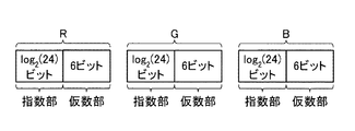
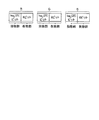
図1は、本発明の第1実施形態に係るRGBの各色の明度を浮動少数点形式で表現するフォーマットの一例を示す図である。
図1において、このフォーマットでは、RGBの各色の明度が、仮数部6ビット、指数部log2(24)ビット(約4.585ビット)の浮動小数点形式で表現される。
ここで、log2(24)ビットの指数部では、m*2n〜m*2n+23の範囲を表現することができる。ただしnは任意の整数、mは仮数部の値である。
図1のフォーマットで表現されたRGBの各色の指数部をまとめて14ビットにエンコードすることができる。
(First embodiment)
FIG. 1 is a diagram showing an example of a format for expressing the brightness of each color of RGB according to the first embodiment of the present invention in a floating-point format.
In FIG. 1, in this format, the brightness of each color of RGB is expressed in a floating-point format with a mantissa part 6 bits and an exponent part log 2 (24) bits (about 4.585 bits).
Here, in the exponent part of log 2 (24) bits, a range of m * 2 n to m * 2 n + 23 can be expressed. However, n is an arbitrary integer, and m is a value of the mantissa part.
The exponent parts of each RGB color expressed in the format of FIG. 1 can be encoded together to 14 bits.
すなわち、3*log2(24)=log2(33*29)<log2(214)という関係を満たすので、RGBの3色分の指数部の情報量は14ビット以下に抑えることができる。
That is, since the
これにより、RGBの各色の仮数部に6ビットずつ割り当てた場合においても、1画素当たりに割り当てられるビット数を32ビット以下に抑えつつ、RGBの各色の指数部に割り当てられるビット数の減少分を抑制することができる。このため、メモリ容量およびメモリバンド幅の増大を抑制しつつ、広いダイナミックレンジを確保するとともに、マッハバンドが知覚されないようにすることができる。 As a result, even when 6 bits are assigned to the mantissa part of each color of RGB, the number of bits assigned to the exponent part of each color of RGB is reduced while keeping the number of bits assigned to one pixel to 32 bits or less. Can be suppressed. Therefore, it is possible to ensure a wide dynamic range and prevent the Mach band from being perceived while suppressing an increase in memory capacity and memory bandwidth.
なお、指数部が0の時、仮数部は非正規化数扱いとするようにしてもよい。この場合、最小分解能は2n−5となり、ダイナミックレンジを2n+23/2n−5=228に拡大することができる。 When the exponent part is 0, the mantissa part may be treated as a denormalized number. In this case, the minimum resolution can be enlarged 2 n-5, and the dynamic range into 2 n + 23/2 n- 5 = 2 28.
(第2実施形態)
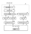
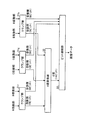
図2は、本発明の第2実施形態に係る画像処理装置の概略構成を示すブロック図である。
図2において、画像処理装置には、画像処理部9、デコーダ6a、6b、エンコーダ7、ピクセルキャッシュ5、テクスチャキャッシュ10およびフレームバッファ8が設けられている。画像処理部9は画像データDの処理を行うことができる。フレームバッファ8は、画像処理部9にて処理される画像データDを記憶することができる。なお、画像データDは、図1のフォーマットを用いたラスタ形式で表現することができる。デコーダ6a、6bは、図1のフォーマットで表現された画像データDを画像処理部9で扱われる形式に変換することができる。エンコーダ7は、画像処理部9で扱われる形式で表現された画像データDを図1のフォーマットの形式に変換することができる。ピクセルキャッシュ5は、属性が付与された画素データを保持することができる。なお、ピクセルキャッシュ5は、例えば、1エントリ(矩形)ずつ画素データを保持することができる。テクスチャキャッシュ10は、フレームバッファ8から読み出した画素の属性を一時的に保持することができる。なお、画素の属性としては、例えば、色、模様、テクスチャなどを挙げることができる。
(Second Embodiment)
FIG. 2 is a block diagram showing a schematic configuration of an image processing apparatus according to the second embodiment of the present invention.
In FIG. 2, the image processing apparatus includes an
ここで、画像処理部9には、頂点処理エンジン1、ラスタライザ2、ピクセル処理エンジン3およびテクスチャエンジン4が設けられている。頂点処理エンジン1は、図形を表現するトライアングルの頂点の座標変換を行うことができる。なお、頂点の座標変換としては、例えば、頂点にて構成される図形の回転、縮小または拡大などに伴う座標変換を挙げることができる。また、頂点処理エンジン1は、コマンドリスト内の描画コマンドおよび描画データ(始点、終点、制御点など)を、ストロークを構成する複数のトライアングルに変換するようにしてもよい。なお、コマンドリストの描画データは、例えば、ベクトル形式などのラスタ形式以外の形式で表現することができる。ラスタライザ2は、頂点で構成されるトライアングルを画素の集まりに変換することができる。テクスチャエンジン4は、画素の属性を保持したり、画素の属性に関する処理を行うことができる。例えば、テクスチャエンジン4は、テクスチャ座標からメモリアドレスを計算したり、テクスチャフィルタとして動作したりすることができる。なお、画素の属性としては、例えば、色、模様、テクスチャなどを挙げることができる。ピクセル処理エンジン3は、テクスチャエンジン4にて取得された属性等を入力とし、任意の演算処理により画素に付与する属性を生成することができる。
Here, the
そして、頂点処理エンジン1において、コマンドリスト内の描画コマンドおよび描画データは、ストロークを構成する複数のトライアングルに変換され、トライアングルを構成する頂点の座標変換が行われた後、ラスタライザ2に入力される。そして、ラスタライザ2において、頂点で構成されるトライアングルが画素の集まりに変換され、ピクセル処理エンジン3に入力される。
Then, in the
一方、フレームバッファ8に記憶された画像データDはテクスチャキャッシュ10を介してデコーダ6bに出力され、図1のフォーマットから画像処理部9で扱われる形式に変換された後、テクスチャエンジン4に送られる。そして、テクスチャエンジン4において画素の属性に関する処理が行われた後、ピクセル処理エンジン3に出力される。また、フレームバッファ8に記憶された画像データDはピクセルキャッシュ5を介してデコーダ6aに出力され、図1のフォーマットから画像処理部9で扱われる形式に変換された後、ピクセル処理エンジン3に送られる。
On the other hand, the image data D stored in the frame buffer 8 is output to the
そして、ピクセル処理エンジン3において、最終的に画素に付与される属性が計算され、エンコーダ7に送られる。そして、エンコーダ7において、画像処理部9で扱われる形式から図1のフォーマットに変換された後、ピクセルキャッシュ5に記憶されている画像データDの上書きなどが行われることで、画像データDが更新される。そして、ピクセル処理エンジン3にて更新されたピクセルキャッシュ5上の画像データDは、フレームバッファ8に記憶される。
Then, in the
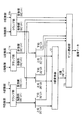
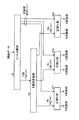
図3は、図1のフォーマットに対応した図2のエンコーダ7の一例を示す図である。
図3において、図2のエンコーダ7には、クランプ部11r、11g、11b、E値変換器12、ビット連結部13が設けられている。クランプ部11r、11g、11bは、画像処理部9で扱われるRGBの各要素の値(以下、RGBの各値と称す。)を図1のフォーマットで表現可能な範囲にクランプすることができる。なお、クランプ部11r、11g、11bは、必要に応じて仮数部を非正規化数に変換する処理を行うようにしてもよい。E値変換器12は、RGBの各値の指数部の上位2ビットを5ビットの圧縮指数コード(E値と称す)に変換することができる。なお、E値変換器12は、演算器群で構成してもよいし、テーブルで構成してもよい。ビット連結部13は、E値変換器12で得られた5ビットのE値と、RGBの各値の指数部の下位3ビットと、RGBの各値の仮数部の6ビットを連結することにより、32ビットの値を生成することができる。なお、エンコーダ7に入力されるRGBの各値は浮動小数点数である。
FIG. 3 is a diagram showing an example of the encoder 7 of FIG. 2 corresponding to the format of FIG.
3, the encoder 7 of FIG. 2 is provided with
そして、RGBの各値がクランプ部11r、11g、11bに入力されると、図1のフォーマットで表現可能な範囲にクランプされ、RGBの各値の指数部の上位2ビットがE値変換器12に出力されるとともに、RGBの各値の指数部の下位3ビットおよびRGBの各値の仮数部の6ビットがビット連結部13に出力される。そして、E値変換器12において、RGBの各値の指数部の上位2ビットが5ビットのE値に変換され、ビット連結部13に出力される。そして、ビット連結部13において、E値変換器12で得られた5ビットのE値と、RGBの各値の指数部の下位3ビットと、RGBの各値の仮数部の6ビットが連結され、図1のフォーマットで表現された画像データDが生成される。
When the RGB values are input to the
具体的には、クランプ部11r、11g、11bでは、RGBの各値のn〜n+23の指数が0〜23の2進コードで表現され、RGBの各要素当たり5ビットで表現される。ここで、RGBの各値の指数部の上位2ビットをRe、Ge、Beとすると、E値変換器12では、例えば、E=Re*32+Ge*3+Beという計算を行うことにより、5ビットのE値を求めることができる。なお、Re、Ge、Beの関係は任意に入れ替え可能である。なお、Re、Ge、Beの取り得る範囲は0〜2なので、Eの範囲は0〜26となる。このため、Eは5ビットで表現可能となり、RGBの各値の指数部の下位3ビットを合わせると、全体で14ビットとなる。
Specifically, in the
ここで、RGBの各色の明度の指数部をlog2(24)ビットで表現することにより、指数部の上位2ビットと下位3ビットを分離して扱うことができる。このため、E値変換器12を6ビット入力5ビット出力とすることができ、E値変換器12の構成を簡単化することができる。
Here, by expressing the exponent part of the brightness of each color of RGB with log 2 (24) bits, the upper 2 bits and the lower 3 bits of the exponent part can be handled separately. For this reason, the
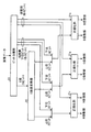
図4は、図1のフォーマットに対応した図2のデコーダ6、8の一例を示す図である。
図4において、図2のデコーダ6、8には、正規化部21r、21g、21b、E値逆変換器22およびビット分離部23が設けられている。ビット分離部23は、図1のフォーマットで表現された32ビットの値を5ビットのE値と、RGBの各値の指数部の下位3ビットと、RGBの各値の仮数部の6ビットに分離することができる。E値逆変換器22は、5ビットのE値をRGBの各値の指数部の上位2ビットに逆変換することができる。なお、E値逆変換器22は、演算器群で構成してもよいし、テーブルで構成してもよい。正規化部21r、21g、21bは、RGBの各値の指数部の上位2ビットと、RGBの各値の指数部の下位3ビットと、RGBの各値の仮数部の6ビットを画像処理部9で扱われるRGBの各値に変換することができる。
FIG. 4 is a diagram showing an example of the decoders 6 and 8 of FIG. 2 corresponding to the format of FIG.
In FIG. 4, the decoders 6 and 8 of FIG. 2 are provided with
そして、図1のフォーマットで表現された画像データDがビット分離部23に入力されると、5ビットのE値と、RGBの各値の指数部の下位3ビットと、RGBの各値の仮数部の6ビットに分離され、5ビットのE値がE値逆変換器22に出力されるとともに、RGBの各値の指数部の下位3ビットおよびRGBの各値の仮数部の6ビットが正規化部21r、21g、21bにそれぞれ出力される。
When the image data D expressed in the format of FIG. 1 is input to the
そして、E値逆変換器22において、5ビットのE値がRGBの各値の指数部の上位2ビットに逆変換され、正規化部21r、21g、21bにそれぞれ出力される。そして、正規化部21r、21g、21bにおいて、RGBの各値の指数部の上位2ビットと、RGBの各値の指数部の下位3ビットと、RGBの各値の仮数部の6ビットとから、浮動小数点フォーマットに従って正規化が行われ、画像処理部9に出力される。
Then, the E value
(第3実施形態)
図5は、本発明の第3実施形態に係るRGBの各色の明度を浮動少数点形式で表現するフォーマットの一例を示す図である。
図5において、このフォーマットでは、RGBの各色の明度が、仮数部6ビット、指数部log2(25)ビット(約4.644ビット)の浮動小数点形式で表現される。
ここで、log2(25)ビットの指数部では、m*2n〜m*2n+24の範囲を表現することができる。ただしnは任意の整数、mは仮数部の値である。
図5のフォーマットで表現されたRGBの各色の指数部をまとめて14ビットにエンコードすることができる。
(Third embodiment)
FIG. 5 is a diagram showing an example of a format that expresses the brightness of each color of RGB according to the third embodiment of the present invention in a floating-point format.
In FIG. 5, in this format, the brightness of each color of RGB is expressed in a floating-point format with a mantissa part 6 bits and an exponent part log 2 (25) bits (about 4.644 bits).
Here, in the exponent part of log 2 (25) bits, a range of m * 2 n to m * 2 n + 24 can be expressed. However, n is an arbitrary integer, and m is a value of the mantissa part.
The exponent part of each color of RGB expressed in the format of FIG. 5 can be collectively encoded to 14 bits.
すなわち、3*log2(25)=log2(56)<log2(214)という関係を満たすので、RGBの3色分の指数部の情報量は14ビット以下に抑えることができる。
That is, since the
これにより、RGBの各色の仮数部に6ビットずつ割り当てた場合においても、1画素当たりに割り当てられるビット数32ビット以下に抑えつつ、RGBの各色の指数部に割り当てられるビット数の減少分を抑制することができる。このため、メモリ容量およびメモリバンド幅の増大を抑制しつつ、広いダイナミックレンジを確保するとともに、マッハバンドが知覚されないようにすることができる。 As a result, even when 6 bits are assigned to the mantissa part of each color of RGB, the decrease in the number of bits assigned to the exponent part of each color of RGB is suppressed while keeping the number of bits assigned to each pixel to 32 bits or less. can do. Therefore, it is possible to ensure a wide dynamic range and prevent the Mach band from being perceived while suppressing an increase in memory capacity and memory bandwidth.
なお、指数部が0の時、仮数部は非正規化数扱いとするようにしてもよい。この場合、最小分解能は2n−5となり、ダイナミックレンジを2n+24/2n−5=229に拡大することができる。 When the exponent part is 0, the mantissa part may be treated as a denormalized number. In this case, the minimum resolution can be enlarged 2 n-5, and the dynamic range into 2 n + 24/2 n- 5 = 2 29.
図6は、図5のフォーマットに対応した図2のエンコーダ7の一例を示す図である。
図6において、図2のエンコーダ7には、クランプ部31r、31g、31b、E値変換器32、ビット連結部33が設けられている。クランプ部31r、31g、31bは、画像処理部9で扱われるRGBの各値を図5のフォーマットで表現可能な範囲にクランプすることができる。なお、クランプ部31r、31g、31bは、必要に応じて仮数部を非正規化数に変換する処理を行うようにしてもよい。E値変換器32は、RGBの各値の指数部の5ビットを14ビットのE値に変換することができる。なお、E値変換器32は、25進数を2進数へ変換する基数変換器と等価であり、演算器群で構成してもよいし、テーブルで構成してもよい。ビット連結部33は、E値変換器32で得られた14ビットのE値と、RGBの各値の仮数部の6ビットを連結することにより、32ビットの値を生成することができる。
FIG. 6 is a diagram illustrating an example of the encoder 7 of FIG. 2 corresponding to the format of FIG.
6, the encoder 7 of FIG. 2 is provided with
そして、RGBの各値がクランプ部31r、31g、31bに入力されると、図5のフォーマットで表現可能な範囲にクランプされ、RGBの各値の指数部の5ビットがE値変換器32に出力されるとともに、RGBの各値の仮数部の6ビットがビット連結部33に出力される。そして、E値変換器32において、RGBの各値の指数部の5ビットが14ビットのE値に変換され、ビット連結部33に出力される。そして、ビット連結部33において、E値変換器32で得られた14ビットのE値と、RGBの各値の仮数部の6ビットが連結され、図5のフォーマットで表現された画像データDが生成される。
When the RGB values are input to the
具体的には、クランプ部31r、31g、31bでは、RGBの各値のn〜n+24の指数が0〜24の2進コードで表現され、RGBの各要素当たり5ビットで表現される。ここで、RGBの各値の指数部の5ビットをRe、Ge、Beとすると、E値変換器32では、例えば、E=Re*252+Ge*25+Beという計算を行うことにより、14ビットのE値を求めることができる。なお、Re、Ge、Beの関係は任意に入れ替え可能である。なお、Re、Ge、Beの取り得る範囲は0〜24なので、Eの範囲は0〜15624となる。このため、Eは14ビットで表現可能となる。
Specifically, in the
ここで、図5のフォーマットでは、E値変換器32が15ビット入力14ビット出力となり、図1のフォーマットを用いた場合に比べて図3のE値変換器12の構成が大規模化するものの、図1のフォーマットよりもダイナミックレンジを拡大することができる。
Here, in the format of FIG. 5, the
図7は、図5のフォーマットに対応した図2のデコーダ6、8の一例を示す図である。
図7において、図2のデコーダ6、8には、正規化部41r、41g、41b、E値逆変換器42およびビット分離部43が設けられている。ビット分離部43は、図5のフォーマットで表現された32ビットの値を14ビットのE値と、RGBの各値の仮数部の6ビットに分離することができる。E値逆変換器42は、14ビットのE値をRGBの各値の5ビットに逆変換することができる。なお、E値逆変換器42は、演算器群で構成してもよいし、テーブルで構成してもよい。正規化部41r、41g、41bは、RGBの各値の指数部の5ビットと、RGBの各値の仮数部の6ビットを画像処理部9で扱われるRGBの各値に変換することができる。
FIG. 7 is a diagram showing an example of the decoders 6 and 8 of FIG. 2 corresponding to the format of FIG.
In FIG. 7, the decoders 6 and 8 of FIG. 2 are provided with
そして、図5のフォーマットで表現された画像データDがビット分離部43に入力されると、14ビットのE値と、RGBの各値の仮数部の6ビットに分離され、14ビットのE値がE値逆変換器42に出力されるとともに、RGBの各値の仮数部の6ビットが正規化部41r、41g、41bにそれぞれ出力される。
Then, when the image data D expressed in the format of FIG. 5 is input to the
そして、E値逆変換器42において、14ビットのE値がRGBの各値の指数部の5ビットに逆変換され、正規化部41r、41g、41bにそれぞれ出力される。そして、正規化部41r、41g、41bにおいて、RGBの各値の指数部の5ビットと、RGBの各値の仮数部の6ビットとから、浮動小数点フォーマットに従って正規化が行われ、画像処理部9に出力される。
Then, in the E-value
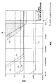
図8は、本発明の実施形態に係るフォーマットで表現された輝度と精度の関係を従来のフォーマットと対比して示す図である。なお、F1は、図1のフォーマットで表現された輝度と精度の関係、F2は、図5のフォーマットで表現された輝度と精度の関係、R16G16B16A16_FLOATで表現された輝度と精度の関係、F4は、R11G11B10_FLOAT(Red、Green)で表現された輝度と精度の関係、F5は、R11G11B10_FLOAT(Blue)で表現された輝度と精度の関係、F6は、R10G10B10A2_FLOATで表現された輝度と精度の関係を示す。 FIG. 8 is a diagram showing the relationship between brightness and accuracy expressed in the format according to the embodiment of the present invention in comparison with the conventional format. F1 is the relationship between the brightness and accuracy expressed in the format of FIG. 1, F2 is the relationship between the brightness and accuracy expressed in the format of FIG. 5, the relationship between the brightness and accuracy expressed in R16G16B16A16_FLOAT, and F4 is The relationship between brightness and accuracy expressed in R11G11B10_FLOAT (Red, Green), F5 indicates the relationship between brightness and accuracy expressed in R11G11B10_FLOAT (Blue), and F6 indicates the relationship between brightness and accuracy expressed in R10G10B10A2_FLOAT.
図8において、R16G16B16A16_FLOATでは、高い精度で広いダイナミックレンジを確保することができるが、1ピクセル当たり64ビット分の容量を消費する。R11G11B10_FLOATでは、Bチャネルの仮数部が5ビットと少ないため、マッハバンドが知覚される領域Rに一部がかかっている。R10G10B10A2_FLOATでは、指数部が3ビットしか割り当てられていないため、マッハバンドが知覚される領域Rに一部がかかっている。 In FIG. 8, R16G16B16A16_FLOAT can secure a wide dynamic range with high accuracy, but consumes a capacity of 64 bits per pixel. In R11G11B10_FLOAT, since the mantissa part of the B channel is as small as 5 bits, a part of the region R where the Mach band is perceived is partially applied. In R10G10B10A2_FLOAT, since only 3 bits are assigned to the exponent part, a part of the region R where the Mach band is perceived is applied.
これに対して、図1および図5のフォーマットでは、マッハバンドが知覚される領域Rを避けつつ、R10G10B10A2_FLOATに比べて広いダイナミックレンジを確保することができる。 On the other hand, in the formats of FIGS. 1 and 5, a wider dynamic range can be ensured compared to R10G10B10A2_FLOAT while avoiding the region R where the Mach band is perceived.
なお、頂点処理エンジン1、ラスタライザ2、ピクセル処理エンジン3、テクスチャエンジン4、デコーダ6a、6bおよびエンコーダ7は、これらのブロックで行われる処理を遂行させる命令が記述されたプログラムをコンピュータに実行させることにより実現することができる。
The
そして、このプログラムをCD−ROMなどの記憶媒体に記憶しておけば、画像処理装置のコンピュータに記憶媒体を装着し、そのプログラムをコンピュータにインストールすることにより、頂点処理エンジン1、ラスタライザ2、ピクセル処理エンジン3、テクスチャエンジン4、デコーダ6a、6bおよびエンコーダ7で行われる処理を実現することができる。
If this program is stored in a storage medium such as a CD-ROM, the
また、頂点処理エンジン1、ラスタライザ2、ピクセル処理エンジン3、テクスチャエンジン4、デコーダ6a、6bおよびエンコーダ7で行われる処理を遂行させる命令が記述されたプログラムをコンピュータに実行させる場合、スタンドアロン型コンピュータで実行させるようにしてもよく、ネットワークに接続された複数のコンピュータに分散処理させるようにしてもよい。
Further, when a computer executes a program in which instructions for performing processing performed by the
1 頂点処理エンジン、2 ラスタライザ、3 ピクセル処理エンジン、4 テクスチャエンジン、5 ピクセルキャッシュ、6a、6b デコーダ、7 エンコーダ、8 フレームバッファ、9 画像処理部、10 テクスチャキャッシュ、11r、11g、11b、31r、31g、31b クランプ部、12、32 E値変換器、13、33 ビット連結部、21r、21g、21b、41r、41g、41b 正規化部、22、42 E値逆変換器、23、43 ビット分離部 1 vertex processing engine, 2 rasterizer, 3 pixel processing engine, 4 texture engine, 5 pixel cache, 6a, 6b decoder, 7 encoder, 8 frame buffer, 9 image processing unit, 10 texture cache, 11r, 11g, 11b, 31r, 31g, 31b Clamp unit, 12, 32 E value converter, 13, 33 bit concatenation unit, 21r, 21g, 21b, 41r, 41g, 41b Normalization unit, 22, 42 E value inverse converter, 23, 43 bit separation Part
Claims (12)
前記データの処理を行う画像処理部とを備えることを特徴とする画像処理装置。 A storage unit for storing data represented in a floating-point format of a first format including a mantissa part in which the color or brightness of a pixel is represented by an integer bit length and an exponent part represented by a non-integer bit length;
An image processing apparatus comprising: an image processing unit that processes the data.
前記第2のフォーマットで表現されるデータを、前記第1のフォーマットのデータに変換するエンコード部とをさらに備えることを特徴とする請求項1記載の画像処理装置。 A decoding unit for converting data expressed in the first format into data expressed in a floating-point format of a second format including a mantissa part expressed in integer bit length and an exponent part expressed in integer bit length When,
The image processing apparatus according to claim 1, further comprising an encoding unit that converts data expressed in the second format into data in the first format.
図形を表現するトライアングルの頂点の座標変換を行う頂点処理部と、
前記頂点で構成されるトライアングルを画素の集まりに変換するラスタライズ部と、
前記画素に属性を付与するピクセル処理部とを備えることを特徴とする請求項1または2記載の画像処理装置。 The image processing unit
A vertex processing unit that performs coordinate conversion of the vertex of a triangle that represents a figure;
A rasterizing unit for converting a triangle composed of the vertices into a collection of pixels;
The image processing apparatus according to claim 1, further comprising: a pixel processing unit that assigns an attribute to the pixel.
前記エンコード部は、
前記第2のフォーマットのデータを前記第1のフォーマットで表現可能な範囲の値にクランプするクランプ部と、
前記RGBの各要素の指数部の上位2ビットを5ビットのE値に変換するE値変換器と、
前記E値変換器で得られた5ビットのE値と、前記RGBの各要素の指数部の下位3ビットと、前記RGBの各要素の仮数部の6ビットを連結することにより、32ビットの値を生成するビット連結部とを備えることを特徴とする請求項2記載の画像処理装置。 The pixel color is expressed by three elements of RGB, and the lightness of each RGB element includes a mantissa part designated by 6 bits and an exponent part designated by log 2 (24) bits. Expressed in a first format,
The encoding unit is
A clamp unit that clamps the data in the second format to a value in a range that can be expressed in the first format;
An E value converter that converts the upper 2 bits of the exponent part of each element of RGB into an E value of 5 bits;
By concatenating the 5-bit E value obtained by the E-value converter, the lower 3 bits of the exponent part of each element of RGB, and the 6 bits of the mantissa part of each element of RGB, a 32-bit value is obtained. The image processing apparatus according to claim 2, further comprising a bit concatenation unit that generates a value.
図形を表現するトライアングルの頂点の座標変換を行う頂点処理部と、
前記頂点で構成されるトライアングルを画素の集まりに変換するラスタライズ部と、
前記画素に属性を付与するピクセル処理部とを備えることを特徴とする請求項5記載の画像処理装置。 The image processing unit
A vertex processing unit that performs coordinate conversion of the vertex of a triangle that represents a figure;
A rasterizing unit for converting a triangle composed of the vertices into a collection of pixels;
The image processing apparatus according to claim 5, further comprising: a pixel processing unit that assigns an attribute to the pixel .
前記第2のフォーマットで表現された32ビットの値を5ビットのE値と、前記RGBの各要素の指数部の下位3ビットと、前記RGBの各要素の仮数部の6ビットに分離するビット分離部と、
前記5ビットのE値を前記RGBの各要素の指数部の上位2ビットに逆変換するE値逆変換器と、
前記RGBの各要素の指数部の上位2ビットと、前記RGBの各要素の指数部の下位3ビットと、前記RGBの各要素の仮数部の6ビットを前記画像処理部で扱われるRGBの各要素に変換する正規化部とを備えることを特徴とする請求項5または6記載の画像処理装置。 The decoding unit
A bit that separates a 32-bit value expressed in the second format into a 5-bit E value, the lower 3 bits of the exponent part of each RGB element, and the 6 bits of the mantissa part of each RGB element A separation unit;
An E value inverse converter that inversely converts the 5-bit E value into the upper 2 bits of the exponent part of each element of RGB;
The upper 2 bits of the exponent part of each of the RGB elements, the lower 3 bits of the exponent part of each of the RGB elements, and the 6 bits of the mantissa part of each of the RGB elements are processed by the image processing unit. the image processing apparatus according to claim 5 or 6, wherein further comprising a normalizing unit that converts an element.
前記エンコード部は、
前記第2のフォーマットのデータを前記第1のフォーマットで表現可能な範囲の値にクランプするクランプ部と、
前記RGBの各要素の指数部の5ビットを14ビットのE値に変換するE値変換器と、
前記E値変換器で得られた14ビットのE値と、前記RGBの各要素の仮数部の6ビットを連結することにより、32ビットの値を生成するビット連結部とを備えることを特徴とする請求項2記載の画像処理装置。 The color of the pixel is expressed by three elements of RGB, and the floating-point format includes a mantissa part in which the brightness of each element of RGB is designated by 6 bits and an exponent part designated by log 2 (25) bits Expressed in a first format,
The encoding unit is
A clamp unit that clamps the data in the second format to a value in a range that can be expressed in the first format;
An E value converter that converts 5 bits of the exponent part of each element of RGB into an E value of 14 bits;
A 14-bit E value obtained by the E-value converter and a bit concatenation unit that generates a 32-bit value by concatenating 6 bits of the mantissa part of each element of RGB. The image processing apparatus according to claim 2 .
図形を表現するトライアングルの頂点の座標変換を行う頂点処理部と、 A vertex processing unit that performs coordinate conversion of the vertex of a triangle that represents a figure;
前記頂点で構成されるトライアングルを画素の集まりに変換するラスタライズ部と、 A rasterizing unit for converting a triangle composed of the vertices into a collection of pixels;
前記画素に属性を付与するピクセル処理部とを備えることを特徴とする請求項9記載の画像処理装置。 The image processing apparatus according to claim 9, further comprising a pixel processing unit that assigns an attribute to the pixel.
前記第2のフォーマットで表現された32ビットの値を14ビットのE値と、前記RGBの各要素の仮数部の6ビットに分離するビット分離部と、 A bit separation unit for separating a 32-bit value expressed in the second format into a 14-bit E value and 6 bits of the mantissa part of each of the RGB elements;
前記14ビットのE値を前記RGBの各要素の指数部の5ビットに逆変換するE値逆変換器と、 An E-value inverse converter that inversely converts the 14-bit E value into 5 bits of the exponent of each element of RGB;
前記RGBの各要素の指数部の5ビットと、前記RGBの各要素の仮数部の6ビットを前記画像処理部で扱われるRGBの各要素に変換する正規化部とを備えることを特徴とする請求項9または10記載の画像処理装置。 And a normalization unit that converts 5 bits of the exponent part of each element of RGB and 6 bits of the mantissa part of each element of RGB into each element of RGB handled by the image processing unit. The image processing apparatus according to claim 9 or 10.
前記画像データを処理するステップとをコンピュータに実行させることを特徴とする画像処理プログラム。 Storing image data expressed in a floating-point format including a mantissa part in which the color or brightness of a pixel is represented by an integer bit length and an exponent part represented by a non-integer bit length;
An image processing program causing a computer to execute the step of processing the image data.
Priority Applications (2)
| Application Number | Priority Date | Filing Date | Title |
|---|---|---|---|
| JP2009284317A JP5367552B2 (en) | 2009-12-15 | 2009-12-15 | Image processing apparatus and image processing program |
| US12/966,354 US8744181B2 (en) | 2009-12-15 | 2010-12-13 | Image processing apparatus and computer readable medium |
Applications Claiming Priority (1)
| Application Number | Priority Date | Filing Date | Title |
|---|---|---|---|
| JP2009284317A JP5367552B2 (en) | 2009-12-15 | 2009-12-15 | Image processing apparatus and image processing program |
Publications (2)
| Publication Number | Publication Date |
|---|---|
| JP2011128714A JP2011128714A (en) | 2011-06-30 |
| JP5367552B2 true JP5367552B2 (en) | 2013-12-11 |
Family
ID=44142975
Family Applications (1)
| Application Number | Title | Priority Date | Filing Date |
|---|---|---|---|
| JP2009284317A Expired - Fee Related JP5367552B2 (en) | 2009-12-15 | 2009-12-15 | Image processing apparatus and image processing program |
Country Status (2)
| Country | Link |
|---|---|
| US (1) | US8744181B2 (en) |
| JP (1) | JP5367552B2 (en) |
Families Citing this family (4)
| Publication number | Priority date | Publication date | Assignee | Title |
|---|---|---|---|---|
| JP5367552B2 (en) * | 2009-12-15 | 2013-12-11 | 株式会社東芝 | Image processing apparatus and image processing program |
| US11350015B2 (en) | 2014-01-06 | 2022-05-31 | Panamorph, Inc. | Image processing system and method |
| US9584701B2 (en) * | 2014-01-06 | 2017-02-28 | Panamorph, Inc. | Image processing system and method |
| US12033361B2 (en) * | 2021-02-05 | 2024-07-09 | Qualcomm Incorporated | Methods and apparatus for lossless compression of GPU data |
Family Cites Families (13)
| Publication number | Priority date | Publication date | Assignee | Title |
|---|---|---|---|---|
| US5561723A (en) * | 1992-03-09 | 1996-10-01 | Tektronix, Inc. | Localized image compression calculation method and apparatus to control anti-aliasing filtering in 3-D manipulation of 2-D video images |
| EP0578950A3 (en) * | 1992-07-15 | 1995-11-22 | Ibm | Method and apparatus for converting floating-point pixel values to byte pixel values by table lookup |
| US6198488B1 (en) * | 1999-12-06 | 2001-03-06 | Nvidia | Transform, lighting and rasterization system embodied on a single semiconductor platform |
| AU2003228353A1 (en) * | 2002-03-22 | 2003-10-13 | Michael F. Deering | Scalable high performance 3d graphics |
| JP4044069B2 (en) * | 2004-04-23 | 2008-02-06 | 株式会社ソニー・コンピュータエンタテインメント | Texture processing apparatus, texture processing method, and image processing apparatus |
| JP4891252B2 (en) * | 2004-11-10 | 2012-03-07 | エヌヴィディア コーポレイション | General-purpose multiply-add function unit |
| JP4037875B2 (en) | 2005-02-24 | 2008-01-23 | 株式会社東芝 | Computer graphics data encoding device, decoding device, encoding method, and decoding method |
| US7873212B2 (en) | 2006-01-24 | 2011-01-18 | Nokia Corporation | Compression of images for computer graphics |
| US8880571B2 (en) * | 2006-05-05 | 2014-11-04 | Microsoft Corporation | High dynamic range data format conversions for digital media |
| US8154554B1 (en) * | 2006-07-28 | 2012-04-10 | Nvidia Corporation | Unified assembly instruction set for graphics processing |
| JP4941285B2 (en) * | 2007-02-20 | 2012-05-30 | セイコーエプソン株式会社 | Imaging apparatus, imaging system, imaging method, and image processing apparatus |
| JP2009282684A (en) * | 2008-05-21 | 2009-12-03 | Fujitsu Ltd | Floating decimal arithmetic unit and dda arithmetic processing method |
| JP5367552B2 (en) * | 2009-12-15 | 2013-12-11 | 株式会社東芝 | Image processing apparatus and image processing program |
-
2009
- 2009-12-15 JP JP2009284317A patent/JP5367552B2/en not_active Expired - Fee Related
-
2010
- 2010-12-13 US US12/966,354 patent/US8744181B2/en not_active Expired - Fee Related
Also Published As
| Publication number | Publication date |
|---|---|
| JP2011128714A (en) | 2011-06-30 |
| US8744181B2 (en) | 2014-06-03 |
| US20110142333A1 (en) | 2011-06-16 |
Similar Documents
| Publication | Publication Date | Title |
|---|---|---|
| JP5251758B2 (en) | Compression encoding apparatus and image display control apparatus | |
| JP5573316B2 (en) | Image processing method and image processing apparatus | |
| JP4698739B2 (en) | Image compression for computer graphics | |
| US8625910B2 (en) | Compression of image data | |
| JP3886184B2 (en) | Image data processing method and image processing apparatus | |
| CN102113305B (en) | High dynamic range texture compression | |
| US20210074027A1 (en) | Image data compression | |
| CN101340587A (en) | Method for encoding input image and method and device for playing encoded image | |
| US12148188B2 (en) | Image data decompression | |
| JP2018142974A (en) | Backward compatible extended image format | |
| US8023752B1 (en) | Decompression of 16 bit data using predictor values | |
| US10475164B2 (en) | Artifact detection in a contrast enhanced output image | |
| JP5367552B2 (en) | Image processing apparatus and image processing program | |
| US20210304446A1 (en) | Image Data Compression | |
| US20180097527A1 (en) | 32-bit hdr pixel format with optimum precision | |
| US8655063B2 (en) | Decoding system and method operable on encoded texture element blocks | |
| US10186236B2 (en) | Universal codec | |
| JP2011175542A (en) | Image data processor | |
| JP2011151572A (en) | Image data processor and operating method thereof | |
| JP2017536740A (en) | Hybrid block-based compression | |
| JP4521835B2 (en) | Image processing device | |
| US20100128059A1 (en) | Decompression system and method for DCT-base compressed graphic data with transparent attribute | |
| JP2009111821A (en) | Image encoding device, image decoding device, image data processing device, image encoding method, and image decoding method | |
| KR101022311B1 (en) | Embedded system using approximate lossless compression technique and its image processing method | |
| CN114581541B (en) | Image compression method and device |
Legal Events
| Date | Code | Title | Description |
|---|---|---|---|
| A621 | Written request for application examination |
Free format text: JAPANESE INTERMEDIATE CODE: A621 Effective date: 20120228 |
|
| A977 | Report on retrieval |
Free format text: JAPANESE INTERMEDIATE CODE: A971007 Effective date: 20130520 |
|
| A131 | Notification of reasons for refusal |
Free format text: JAPANESE INTERMEDIATE CODE: A131 Effective date: 20130528 |
|
| A521 | Request for written amendment filed |
Free format text: JAPANESE INTERMEDIATE CODE: A523 Effective date: 20130724 |
|
| TRDD | Decision of grant or rejection written | ||
| A01 | Written decision to grant a patent or to grant a registration (utility model) |
Free format text: JAPANESE INTERMEDIATE CODE: A01 Effective date: 20130820 |
|
| A61 | First payment of annual fees (during grant procedure) |
Free format text: JAPANESE INTERMEDIATE CODE: A61 Effective date: 20130911 |
|
| R151 | Written notification of patent or utility model registration |
Ref document number: 5367552 Country of ref document: JP Free format text: JAPANESE INTERMEDIATE CODE: R151 |
|
| LAPS | Cancellation because of no payment of annual fees |