JP5367532B2 - Reinforcing strip, flexible tube for transporting fluid, method for manufacturing reinforcing strip, and manufacturing method of flexible tube for transporting fluid - Google Patents
Reinforcing strip, flexible tube for transporting fluid, method for manufacturing reinforcing strip, and manufacturing method of flexible tube for transporting fluid Download PDFInfo
- Publication number
- JP5367532B2 JP5367532B2 JP2009245189A JP2009245189A JP5367532B2 JP 5367532 B2 JP5367532 B2 JP 5367532B2 JP 2009245189 A JP2009245189 A JP 2009245189A JP 2009245189 A JP2009245189 A JP 2009245189A JP 5367532 B2 JP5367532 B2 JP 5367532B2
- Authority
- JP
- Japan
- Prior art keywords
- reinforcing
- reinforcing strip
- layer
- strip
- flexible tube
- Prior art date
- Legal status (The legal status is an assumption and is not a legal conclusion. Google has not performed a legal analysis and makes no representation as to the accuracy of the status listed.)
- Expired - Fee Related
Links
Images
Landscapes
- Laminated Bodies (AREA)
- Rigid Pipes And Flexible Pipes (AREA)
Abstract
Description
本発明は、海底油ガス田等から産出した油やガスを輸送するための流体輸送用可撓管およびこれに用いられる補強条等に関するものである。 TECHNICAL FIELD The present invention relates to a flexible pipe for transporting fluid for transporting oil and gas produced from a submarine oil and gas field and the like, and a reinforcing strip and the like used therefor.
従来、海底油ガス田から算出する高圧の油やガスは、流体輸送用可撓管によって浮遊式石油生産設備まで輸送される。可撓管には、耐内圧特性や液密性、防水性等が要求されている。 Conventionally, high-pressure oil or gas calculated from a submarine oil and gas field is transported to a floating oil production facility by a flexible pipe for fluid transportation. The flexible tube is required to have internal pressure resistance, liquid tightness, waterproofness, and the like.
このような流体輸送用可撓管としては、例えば、最内層に、可撓性に優れ、耐外圧および敷設時の耐側圧補強に優れるステンレス製のインターロック管を用い、その外周部に、耐油ガス性に優れ、液密性に優れるプラスチック内管が設けられ、さらにその外周に耐内圧補強としての金属製内圧補強層および軸方向補強としての金属製軸力補強層が設けられ、最外層に防水層としてのプラスチックシースが設けられ、軸力補強層には等価比重1.0以下の軽量平型材を介在させ、平型補強層の炭素含有率を規定した可撓性流体輸送管がある(特許文献1)。 As such a flexible pipe for transporting fluid, for example, a stainless steel interlock pipe excellent in flexibility and excellent in external pressure resistance and lateral pressure resistance during laying is used in the innermost layer, and an oil A plastic inner pipe with excellent gas and liquid tightness is provided, and a metal internal pressure reinforcement layer as an internal pressure reinforcement and a metal axial force reinforcement layer as an axial reinforcement are provided on the outer periphery, and the outermost layer is provided as an outer layer. A plastic sheath is provided as a waterproof layer, a lightweight flat material with an equivalent specific gravity of 1.0 or less is interposed in the axial force reinforcing layer, and there is a flexible fluid transport pipe that defines the carbon content of the flat reinforcing layer ( Patent Document 1).
しかし、特許文献1のような可撓性流体輸送管は、軸方向補強として金属製軸力補強層が設けられるが、より深い海底から油ガスを汲み上げる場合には、より長さの長い可撓性流体輸送管を用いる必要がある。このため、輸送管全体の重量が増加する。したがって、この重量にも耐えうるような軸力補強が必要となる。このようなより高い軸力補強を得るためには、より強度の高い金属を用いるか、軸力補強層の厚みを厚くする必要がある。
However, the flexible fluid transport pipe as in
しかし、高強度の金属を用いることはコスト増につながり、軸力補強層の厚みを厚くしたのでは、ますます輸送管の重量増につながる。このため、より軽量かつ高強度な軸力補強手段が望まれている。 However, the use of a high-strength metal leads to an increase in cost, and increasing the thickness of the axial force reinforcing layer further increases the weight of the transport pipe. For this reason, a lighter and higher strength axial force reinforcing means is desired.
一方、汲み上げる原油成分中に硫化水素等の腐食ガス成分が多い場合には、原油の輸送中に流化水素ガスが樹脂層を浸透し、金属性の補強層が腐食する恐れがある。このため、補強層の耐食性の向上が必要である。たとえば、耐内圧補強層としては、通常引張強度100kgf/mm2程度の低炭素鋼が使用されるが、鋼材の耐食性の向上のため熱処理が施される。熱処理法により、耐内圧補強層の強度と耐食性とを両立させることができる。 On the other hand, when the crude oil component to be pumped contains a lot of corrosive gas components such as hydrogen sulfide, the hydrogenated hydrogen gas may permeate the resin layer during transportation of the crude oil, and the metallic reinforcing layer may corrode. For this reason, it is necessary to improve the corrosion resistance of the reinforcing layer. For example, a low carbon steel having a tensile strength of about 100 kgf / mm 2 is usually used as the internal pressure resistant layer, but heat treatment is performed to improve the corrosion resistance of the steel material. By the heat treatment method, both the strength and corrosion resistance of the internal pressure-proof reinforcing layer can be achieved.
しかし、軸力補強層(補強条)は、懸架荷重や高内圧の軸方向伸び荷重に対抗するため、引張強度200kgf/mm2程度まで高張力化する必要があり、このため、通常、高炭素鋼が用いられる。しかし、高炭素鋼を低炭素鋼と同様に熱処理を行うと、著しく引張強度が低下するため、耐食性と強度との両立が困難であるという問題がある。 However, the axial force reinforcing layer (reinforcing strip) needs to be increased to a tensile strength of about 200 kgf / mm 2 in order to resist a suspension load or a high internal pressure axial extension load. Steel is used. However, when a high carbon steel is heat-treated in the same manner as a low carbon steel, the tensile strength is remarkably lowered, so that there is a problem that it is difficult to achieve both corrosion resistance and strength.
そこで、このような輸送管の構成部材として樹脂化が進められている。樹脂化により、軽量かつ耐食性に優れる輸送管を得ることができる。しかし、軸力補強は補強条をロングピッチで螺旋巻きして形成され、通常は、複数本の補強条が長手方向に接合されて用いられる。金属製の補強条を用いる場合には、補強条の端部同士を突き合わせ溶接により接合すれば、十分な接合強度を確保することができるが、樹脂製の補強条は溶接することができない。 Then, resin-ized as a structural member of such a transport pipe is progressing. By using resin, a transport pipe that is lightweight and excellent in corrosion resistance can be obtained. However, the axial force reinforcement is formed by spirally winding a reinforcing strip at a long pitch, and usually a plurality of reinforcing strips are used by being joined in the longitudinal direction. In the case of using a metal reinforcing strip, if the ends of the reinforcing strip are joined by butt welding, a sufficient joint strength can be ensured, but the resin reinforcing strip cannot be welded.
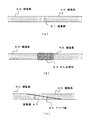
図7は、樹脂製の補強条60同士を接合した状態を示す図である。図7(a)に示す従来のように、補強条60の端部同士を突き合わせ、互いの端部を接着面61として接着するのでは、十分な強度を得ることはできない。 FIG. 7 is a diagram showing a state where the resin reinforcing strips 60 are joined together. If the ends of the reinforcing strips 60 are brought into contact with each other and bonded to each other as the bonding surface 61 as in the conventional case shown in FIG. 7A, sufficient strength cannot be obtained.
また、図7(b)に示すように、補強条60同士の端部を突き合わせ、かしめ部材63などを用いた機械接合を行うと、接合部の厚みが厚くなり管径を一定に保つことができず、また、強度ばらつきが大きいという問題ある。特に、過度の力を付与すると、補強条60自体が破損する恐れがある。 Further, as shown in FIG. 7B, when the end portions of the reinforcing strips 60 are butted together and mechanical joining using the caulking member 63 or the like is performed, the thickness of the joining portion increases and the tube diameter can be kept constant. In addition, there is a problem that the intensity variation is large. In particular, if an excessive force is applied, the reinforcing strip 60 itself may be damaged.
このような補強条60同士の接着としては、例えば図7(c)に示すように、互いの接触部にテーパ部65を形成し、より広い接着面67を設ける方法がある。接着面67を広く取ることができれば、より高い接着強度を高めることができる。しかし、このような端部加工は極めて困難であり、接着強度自体にもばらつきが生じる恐れがある。このため、補強条60同士をより簡単にかつ確実に接合可能な方法が望まれている。 For example, as shown in FIG. 7C, there is a method in which a taper portion 65 is formed at each contact portion and a wider bonding surface 67 is provided as the bonding between the reinforcing strips 60. If the adhesive surface 67 can be widened, higher adhesive strength can be increased. However, such end processing is extremely difficult, and the adhesive strength itself may vary. For this reason, the method which can join the reinforcing strips 60 more simply and reliably is desired.
本発明は、このような問題に鑑みてなされたもので、軽量であり、接合が容易な軸力補強層に用いられる補強条、およびこれを用いた流体輸送用可撓管等を提供することを目的とする。 The present invention has been made in view of such problems, and provides a reinforcing strip used for an axial force reinforcing layer that is lightweight and easy to join, a flexible tube for fluid transportation using the same, and the like. With the goal.
前述した目的を達成するため、第1の発明は、流体輸送用可撓管の軸力補強層に用いられる補強条であって、前記補強条は、繊維強化プラスチック製の帯状部材であり、前記補強条の端部近傍の内部には剥離部材が設けられ、前記補強条の端部は厚さ方向に剥離可能であることを特徴とする補強条である。 In order to achieve the above-mentioned object, the first invention is a reinforcing strip used for an axial force reinforcing layer of a flexible tube for fluid transportation, wherein the reinforcing strip is a belt-shaped member made of fiber reinforced plastic, A peeling member is provided inside the vicinity of the end of the reinforcing strip, and the end of the reinforcing strip is peelable in the thickness direction.
前記剥離部材は、前記補強条の端部から長手方向に対し、前記補強条の厚みの50倍以上の長さの範囲に設けられることが望ましい。前記補強条は、ポリオレフィン系樹脂で被覆されることが望ましい。 It is desirable that the peeling member is provided in a range of 50 times or more the thickness of the reinforcing strip in the longitudinal direction from the end of the reinforcing strip. The reinforcing strip is preferably coated with a polyolefin resin.
第1の発明によれば、補強条が繊維強化プラスチック製であるため軽量・高強度であり、かつ、端部が剥離可能であるため、剥離部を接着部に使用することができる。補強条の端部を厚さ方向に剥離すれば、広い接着面積を得ることができ、高い接着強度を得ることができる。なお、剥離部の長さが、厚さの50倍以上であれば、十分な接着強度(接着面積)を得ることができる。 According to the first invention, since the reinforcing strip is made of fiber reinforced plastic, it is lightweight and high in strength, and since the end portion can be peeled off, the peeling portion can be used as the bonding portion. If the end of the reinforcing strip is peeled in the thickness direction, a wide bonding area can be obtained, and a high bonding strength can be obtained. In addition, if the length of a peeling part is 50 times or more of thickness, sufficient adhesive strength (adhesion area) can be obtained.
また、補強条がポリオレフィン系樹脂で被覆されれば、補強条同士の摩擦や、他の層との接触による摩耗等よる破損の恐れがない。 Moreover, if the reinforcing strip is coated with a polyolefin-based resin, there is no fear of damage due to friction between the reinforcing strips or wear due to contact with other layers.
第2の発明は、第1の発明に係る補強条を用いた流体輸送用可撓管であって、可撓性を有する管体と、前記管体の外周部に設けられた遮蔽層と、前記遮蔽層の外周部に設けられた耐内圧補強層と、前記耐内圧補強層の外周部に設けられた軸力補強層と、前記軸力補強層の外周部に設けられたシース層と、を具備し、前記軸力補強層は、前記補強条が前記耐内圧補強層の周方向に複数配置され、前記耐内圧補強層の外周部に螺旋状に巻き付けられ、さらに前記補強条が長手方向に複数接合されることで形成され、前記補強条の端部の前記剥離部材の設けられる範囲が、厚さ方向に剥離され、剥離された部位が切除されることで前記補強条の端部には段差が形成されており、前記補強条の長手方向に対向するそれぞれの前記段差が重ね合わされ、前記補強条の長手方向に略垂直な方向の面同士が接着されることで、前記補強条が長手方向に複数接合されることを特徴とする流体輸送用可撓管である。 The second invention is a flexible tube for fluid transportation using the reinforcing strip according to the first invention, and has a flexible tube, a shielding layer provided on the outer periphery of the tube, An internal pressure-resistant reinforcing layer provided on the outer peripheral portion of the shielding layer; an axial force reinforcing layer provided on the outer peripheral portion of the internal pressure-resistant reinforcing layer; and a sheath layer provided on the outer peripheral portion of the axial force reinforcing layer; The axial force reinforcing layer includes a plurality of the reinforcing strips arranged in a circumferential direction of the internal pressure-proof reinforcing layer, wound spirally around an outer peripheral portion of the internal pressure-proof reinforcing layer, and the reinforcing strip is further longitudinally The range where the peeling member is provided at the end of the reinforcing strip is peeled off in the thickness direction, and the peeled portion is cut off at the end of the reinforcing strip. Is formed with a step, and each of the steps facing the longitudinal direction of the reinforcing strip is superimposed, Serial By substantially perpendicular direction of the surface between the longitudinal direction of the reinforcing strip is bonded, is a fluid transport flexible tube, characterized in that said reinforcing strip is more joined longitudinally.
第2の発明によれば、軽量な繊維強化ブラスチック製の補強条を用いて軸力補強層が形成されるため、軽量であり、かつ、補強条の端部同士が剥離部で接着されるため、ひろい接着面積を確保できるため、接着強度に優れる。したがって、確実に軸力補強層を形成でき、軽量かつ高強度であり、同一外径を有する可撓管を得ることができる。 According to the second invention, since the axial force reinforcing layer is formed by using a lightweight fiber-reinforced plastic reinforcing strip, it is lightweight and the ends of the reinforcing strip are bonded to each other at the peeling portion. Therefore, since a wide bonding area can be secured, the bonding strength is excellent. Therefore, an axial force reinforcing layer can be reliably formed, and a flexible tube having the same outer diameter that is lightweight and high in strength can be obtained.
第3の発明は、流体輸送用可撓管の軸力補強層に用いられる補強条の製造方法であって、複数の繊維部材を複数のグループに分けて集合して複数の繊維部材集合体を形成し、複数の前記繊維部材集合体の先端部および後端部において、複数の前記繊維部材集合体の間に剥離部材を挿入し、複数の前記繊維部材集合体を一体化するように樹脂を供給して帯状の繊維強化ブラスチックを形成することを特徴とする補強条の製造方法である。 A third invention is a method for manufacturing a reinforcing strip used for an axial force reinforcing layer of a flexible tube for fluid transportation, and a plurality of fiber members are assembled by dividing a plurality of fiber members into a plurality of groups. And forming a resin so that the plurality of fiber member assemblies are integrated by inserting a peeling member between the plurality of fiber member assemblies at the front end portion and the rear end portion of the plurality of fiber member assemblies. This is a method for producing a reinforcing strip, characterized in that it is supplied to form a strip-like fiber-reinforced plastic.
前記帯状の繊維強化プラスチックの外周に、さらにポリオレフィン系樹脂を被覆してもよい。 A polyolefin resin may be further coated on the outer periphery of the belt-shaped fiber reinforced plastic.
第3の発明によれば、補強条の製造方法において、複数の繊維部材集合体を形成し、繊維部材集合体の間に剥離部材を挿入した状態で、樹脂を供給するため、剥離部材が確実に埋設される。また、剥離部材が設けられていない部位には、確実に繊維部材が設けられるため、高い強度を得ることができる。したがって、簡易にかつ確実に、軽量かつ高強度であり接合性に優れる補強条を得ることができる。また、外周にポリオレフィン件樹脂を設ければ、表面の耐摩耗性に優れる補強条を得ることができる。 According to the third invention, in the method for manufacturing a reinforcing strip, a plurality of fiber member assemblies are formed, and the resin is supplied in a state where the release members are inserted between the fiber member assemblies. Buried in Moreover, since the fiber member is reliably provided in the site | part in which the peeling member is not provided, high intensity | strength can be obtained. Accordingly, it is possible to easily and reliably obtain a reinforcing strip that is lightweight and has high strength and excellent bondability. If a polyolefin resin is provided on the outer periphery, a reinforcing strip having excellent surface wear resistance can be obtained.
第4の発明は、流体輸送用可撓管の製造方法であって、先端および後端における内部に、厚さ方向に剥離可能な剥離部材が設けられた繊維強化プラスチック製の補強条を用い、可撓性を有する管体の周囲に樹脂を押し出し被覆して遮蔽層を形成する工程と、前記遮蔽層の外周に耐内圧用補強条を短ピッチで巻き付けて耐内圧補強層を形成する工程と、前記耐内圧補強層の外周に、複数の前記補強条を周方向に並列した状態から長ピッチで巻き付けて軸力補強層を形成する工程と、前記軸力補強層の外周にシースを押出し被覆してシース層を形成する工程と、を具備し、前記補強条の巻き付けの際、長手方向に接合される1対の補強条の対向するそれぞれの先端部および後端部において、前記剥離部材によって前記補強条を厚さ方向に剥離し、剥離された部位を切除することでそれぞれ段差を形成し、一対の前記補強条の前記段差同士を重ね合わせ、前記補強条の長手方向に略垂直な方向の面同士を接着して接合することを特徴とする流体輸送用可撓管の製造方法である。 4th invention is the manufacturing method of the flexible pipe | tube for fluid transportation, Comprising: The inside of the front-end | tip and a rear end uses the reinforcing strip made from the fiber reinforced plastic provided with the peeling member which can be peeled in the thickness direction, A step of forming a shielding layer by extruding and covering a resin around a flexible tube; and a step of forming an inner pressure-resistant reinforcing layer by winding an inner pressure-resistant reinforcing strip at a short pitch around the outer periphery of the shielding layer; A step of forming an axial force reinforcing layer by winding a plurality of the reinforcing strips on the outer periphery of the internal pressure-proof reinforcing layer at a long pitch from a state in which the reinforcing strips are arranged in the circumferential direction; Forming a sheath layer, and at the time of winding of the reinforcing strip, at the respective front end portion and rear end portion facing each other of the pair of reinforcing strips joined in the longitudinal direction by the peeling member The reinforcing strip is peeled off in the thickness direction, Forming a step by cutting away the separated parts, overlapping the steps of the pair of reinforcing strips, bonding and joining surfaces in a direction substantially perpendicular to the longitudinal direction of the reinforcing strips It is the manufacturing method of the flexible tube for fluid transportation characterized.
前記補強条は熱硬化性樹脂をマトリックスとする繊維強化プラスチックであり、
前記補強条を前記耐内圧補強層の外周に巻きつける際、前記補強条を加熱して軟化させ、前記補強条が巻きつけられる円弧状の面に沿って前記補強条を変形させてもよい。
The reinforcing strip is a fiber reinforced plastic having a thermosetting resin as a matrix,
When the reinforcing strip is wound around the outer periphery of the internal pressure-resistant reinforcing layer, the reinforcing strip may be heated and softened, and the reinforcing strip may be deformed along an arcuate surface around which the reinforcing strip is wound.
第4の発明によれば、補強条の端部に設けられた剥離部材によって、補強条端部を厚さ方向に剥離するとこで、容易に広い接着面を得ることができ、高い接着性を得ることができる。また、補強条の素材として熱硬化性樹脂を用い、補強条の巻き付け時に加熱することで、補強条が巻きつけ面の円弧上面に沿って変形し、確実に補強条を巻きつけることができる。 According to the fourth invention, the peeling member provided at the end portion of the reinforcing strip can peel the reinforcing strip end portion in the thickness direction, so that a wide bonding surface can be easily obtained, and high adhesiveness can be obtained. Can be obtained. Further, by using a thermosetting resin as the material of the reinforcing strip and heating at the time of winding the reinforcing strip, the reinforcing strip is deformed along the upper surface of the arc of the winding surface, and the reinforcing strip can be reliably wound.
本発明によれば、軽量であり、接合が容易な軸力補強層に用いられる補強条、およびこれを用いた流体輸送用可撓管等を提供することができる。 According to the present invention, it is possible to provide a reinforcing strip used for an axial force reinforcing layer that is lightweight and easy to join, a flexible tube for fluid transportation using the same, and the like.
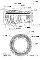
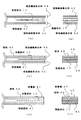
以下、本発明の実施の形態にかかる可撓管1について説明する。図1は、可撓管1を示す図で、図1(a)は可撓管1の斜視断面図、図1(b)は断面図である。可撓管1は、主に管体であるインターロック管3、遮蔽層5、耐内圧補強層7、軸力補強層9、シース層11等から構成される。
Hereinafter, the
インターロック管3は、可撓管1の最内層に位置し、外圧に対する座屈強度に優れ、耐食性も良好なステンレス製である。インターロック管3はテープを断面S字形状に成形させてS字部分で互いに噛み合わせて連結されて構成され、可撓性を有する。なお、インターロック管3に代えて、同様の可撓性を有し、座屈強度等に優れる管体であれば、他の態様の管体を使用することも可能である。
The
インターロック管3の外周部には、遮蔽層5が設けられる。遮蔽層5は、インターロック管3内を流れる流体を遮蔽する。遮蔽層5は、例えばナイロン等の樹脂製である。なお、インターロック管3と遮蔽層5との間に座床層13aを設けてもよい。座床層13aは、必要に応じて設けられ、インターロック管3の外周の凹凸形状を略平らにならすための層であり、インターロック管3の可撓性に追従して変形可能である。すなわち、座床層13aは、例えば不織布等のようにある程度の厚みを有し、インターロック管3外周の凹凸のクッションとしての役割を有する。
A shielding layer 5 is provided on the outer periphery of the
なお、インターロック管3の外周部に遮蔽層5が設けられるとは、必ずしもインターロック管3と遮蔽層5とが接触していることを要せず、例えば、座床層13aのような他層が間に挟まれて設けられたとしても、遮蔽層5は、インターロック管3の「外周部に」設けられていると称する。以下の説明においては、同様にして「外周部」(または単に「外周」)なる用語を用いる。
The provision of the shielding layer 5 on the outer periphery of the
遮蔽層5の外周部には、耐内圧補強層7が設けられる。耐内圧補強層7は、主にインターロック管3内を流れる流体の内圧等に対する補強層である。耐内圧補強層7は、例えば断面C形状または断面Z形状等の金属製のテープ等を互いに向かい合うように、かつ、互いに軸方向に重なり合うように短ピッチ(金属製のテープの幅と巻きつけピッチが略同じ)で巻きつけられて形成される。なお、耐内圧補強層7は、上述のように金属テープが所定ピッチで巻きつけられた構成であり、インターロック管3の曲げ変形等に追従可能である。
On the outer periphery of the shielding layer 5, an internal pressure-proof reinforcing layer 7 is provided. The internal pressure-resistant reinforcing layer 7 is a reinforcing layer for the internal pressure of fluid mainly flowing in the
耐内圧補強層7の外周には、軸力補強層9が設けられる。軸力補強層9は、主にインターロック管3が可撓管1の軸方向へ変形する(伸びる)ことを抑えるための補強層である。軸力補強層9は、平型断面形状の補強条15をロングピッチで(補強条の幅に対して巻きつけピッチが十分に長くなるように)2層交互巻きして形成される。補強条15は耐内圧補強層の外周において、周方向に複数配置され、ロングピッチで巻きつけられる。軸力補強層9は、インターロック管3の可撓性に追従して変形可能である。
An axial force reinforcing layer 9 is provided on the outer periphery of the internal pressure-resistant reinforcing layer 7. The axial force reinforcing layer 9 is a reinforcing layer for mainly suppressing the
なお、必要に応じて、耐内圧補強層7と軸力補強層9の間にポリエチレン製等の樹脂テープである座床層13bを設けてもよく、また、逆向きに螺旋状に巻きつけられる2層の補強条15の間に、座床層13cを設けてもよい。座床層13b、13cは、補強部材同士が可撓管1の変形に追従する際に擦れて、摩耗することを防止するためである。この場合でも、座床層の有無を問わず、耐内圧補強層7の外周部に軸力補強層9が設けられると称する。なお、補強条15は、長手方向に複数接合して巻きつけられる。補強条15の詳細は後述する。
If necessary, a floor layer 13b, which is a resin tape made of polyethylene or the like, may be provided between the internal pressure-proof reinforcing layer 7 and the axial force reinforcing layer 9, and is wound spirally in the reverse direction. A floor layer 13 c may be provided between the two reinforcing strips 15. The floor layers 13b and 13c are for preventing the reinforcing members from being worn by rubbing when the reinforcing members follow the deformation of the
軸力補強層9の外周部には、シース層11が設けられる。シース層11は、例えば海水等が補強層へ浸入することを防止するための層である。シース層11は、例えばポリエチレン製やポリアミド系合成樹脂製等が使用できる。なお、軸力補強層9の外周には、必要に応じて座床層13dが設けられる。座床層13dは、軸力補強層9の外周の凹凸形状を略平らにならすための層であり、インターロック管3の可撓性に追従して変形可能である。以上のように、可撓管1を構成する各層は、それぞれ可撓管1の曲げ変形等に追従し、可撓性を有する。
A sheath layer 11 is provided on the outer peripheral portion of the axial force reinforcing layer 9. The sheath layer 11 is a layer for preventing seawater or the like from entering the reinforcing layer, for example. The sheath layer 11 can be made of, for example, polyethylene or polyamide synthetic resin. A floor layer 13d is provided on the outer periphery of the axial force reinforcing layer 9 as necessary. The seat floor layer 13d is a layer for leveling the uneven shape on the outer periphery of the axial force reinforcing layer 9 and can be deformed following the flexibility of the
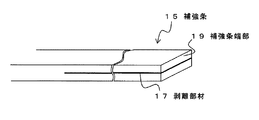
次に、補強条15について説明する。図2は補強条15の端部近傍の斜視図であり、図3は補強条15の側面図である。補強条15は、断面平板状の帯状部材であり、繊維強化プラスチック製である。補強条15としては、例えば、幅10mm程度、厚み4〜5mm程度でよい。 Next, the reinforcing strip 15 will be described. FIG. 2 is a perspective view of the vicinity of the end of the reinforcing strip 15, and FIG. 3 is a side view of the reinforcing strip 15. The reinforcing strip 15 is a belt-like member having a flat cross section and is made of fiber reinforced plastic. For example, the reinforcing strip 15 may have a width of about 10 mm and a thickness of about 4 to 5 mm.
補強条15を構成する高強度繊維としては、たとえば、太さ0.1mm〜1.0mm程度のアラミド繊維やカーボン繊維等が用いられる。また、補強条15を構成するマトリックス樹脂としては、ポリオレフィン系樹脂が用いられる。なお、図示は省略するが、表面には、ポリエチレン等の被覆層が形成される。 As the high-strength fibers constituting the reinforcing strip 15, for example, aramid fibers or carbon fibers having a thickness of about 0.1 mm to 1.0 mm are used. A polyolefin resin is used as the matrix resin constituting the reinforcing strip 15. Although illustration is omitted, a coating layer such as polyethylene is formed on the surface.
図2および図3(a)に示すように、補強条15の端部には、厚み方向の略中央に、剥離部材17が設けられる。剥離部材17は、補強条端部19から全幅方向にわたって設けられる。剥離部材17の長手方向Lは、補強条15の厚さTの50倍以上とすることが望ましい(図3(a))。たとえば、補強条端部19から200〜250mm程度の範囲に剥離部材17が設けられれば良い。なお、剥離部材17の長手方向の設置範囲については、必要な接着面積を確保するためである。また、剥離部材17は、樹脂成形時に樹脂同士が融着等せず、剥離可能であればよく、例えばアルミニウム等の金属フィルムが用いられる。 As shown in FIG. 2 and FIG. 3A, a peeling member 17 is provided at the end of the reinforcing strip 15 at the approximate center in the thickness direction. The peeling member 17 is provided from the reinforcing strip end portion 19 over the entire width direction. The longitudinal direction L of the peeling member 17 is desirably 50 times or more the thickness T of the reinforcing strip 15 (FIG. 3A). For example, the peeling member 17 should just be provided in the range of about 200-250 mm from the reinforcing strip end part 19. In addition, about the installation range of the longitudinal direction of the peeling member 17, it is for ensuring a required adhesion area. Moreover, the peeling member 17 should just be able to peel, without resin melt | fusion etc. at the time of resin molding, for example, metal films, such as aluminum, are used.
図3(b)に示すように、剥離部材17が設けられる範囲では、補強条15を構成するマトリックス樹脂が一体化されておらず、このため、剥離部材17の設置範囲では、補強条15を厚み方向に容易に剥離することができる。 As shown in FIG. 3B, in the range where the peeling member 17 is provided, the matrix resin constituting the reinforcing strip 15 is not integrated. Therefore, in the installation range of the peeling member 17, the reinforcing strip 15 is It can be easily peeled in the thickness direction.
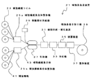
次に、補強条15の製造方法について説明する。図4は、補強条製造装置21を示す概略図である。補強条製造装置21は、主に、補強繊維コイル23、補強繊維集合体整形機25a、25b、剥離部材供給機29、引取機27、樹脂供給・硬化装置31、冷却機33、被覆装置35、整形装置37、補強条巻き取り機39等から構成される。 Next, a method for manufacturing the reinforcing strip 15 will be described. FIG. 4 is a schematic view showing the reinforcing strip manufacturing apparatus 21. The reinforcing strip manufacturing apparatus 21 mainly includes a reinforcing fiber coil 23, reinforcing fiber assembly shaping machines 25a and 25b, a peeling member supply machine 29, a take-up machine 27, a resin supply / curing apparatus 31, a cooling machine 33, a coating apparatus 35, It comprises a shaping device 37, a reinforcing strip winder 39 and the like.
補強繊維コイル23は、繊維部材である補強繊維41が巻きつけられた複数のコイルである。補強繊維コイル23から送られた補強繊維41は、補強繊維集合体整形機25a、25bに送られる。補強繊維集合体整形機25a、25bは、送られてきた複数の補強繊維を、補強条の断面形状に合わせて、例えば矩形等の断面形状に配列して整形し、補強繊維集合体43を形成する。なお、補強繊維コイル23の個数や補強繊維集合体整形機25a、25bの台数は図4の例には限られない。実際には、より多数の補強繊維コイルが用いられ、また、補強繊維集合体が3つ以上形成される場合には、これに見合った台数の補強繊維集合体整形機を用いればよい。以下の説明では、二つの補強繊維集合体43を形成する場合について説明する。 The reinforcing fiber coil 23 is a plurality of coils around which reinforcing fibers 41 that are fiber members are wound. The reinforcing fiber 41 sent from the reinforcing fiber coil 23 is sent to the reinforcing fiber assembly shaping machines 25a and 25b. The reinforcing fiber assembly shaping machines 25a and 25b form the reinforcing fiber assembly 43 by arranging and shaping the plurality of sent reinforcing fibers in accordance with the cross-sectional shape of the reinforcing strip, for example, in a cross-sectional shape such as a rectangle. To do. The number of reinforcing fiber coils 23 and the number of reinforcing fiber assembly shaping machines 25a and 25b are not limited to the example shown in FIG. Actually, a larger number of reinforcing fiber coils are used, and when three or more reinforcing fiber assemblies are formed, the number of reinforcing fiber assembly shaping machines corresponding to this may be used. In the following description, a case where two reinforcing fiber assemblies 43 are formed will be described.
二つのグループに分けられた補強繊維集合体43は、引取機27により引き取られる。この際、製造される補強条の先端部および後端部においては、剥離部材供給機29より供給される剥離部材が挟み込まれる。 The reinforcing fiber assemblies 43 divided into two groups are taken up by the take-up machine 27. Under the present circumstances, the peeling member supplied from the peeling member supply machine 29 is inserted | pinched in the front-end | tip part and rear-end part of the reinforcing strip manufactured.
図5(a)は、補強繊維集合体43および剥離部材17を示す側方図であり、図5(b)は正面図である。図に示すように、複数の補強繊維が整列して形成される二つのグループの補強繊維集合体43の間に、剥離部材17が挿入される。剥離部材17は、金属フィルムを折り返して形成された部材であり、製造される補強条の幅と略同じ幅で、所定の長さ範囲に設けられる。なお、さらに複数のグループの補強繊維集合体43を用いる場合には、それぞれの補強繊維集合体間に剥離部材17を設ければよい。 FIG. 5A is a side view showing the reinforcing fiber assembly 43 and the peeling member 17, and FIG. 5B is a front view. As shown in the figure, the peeling member 17 is inserted between two groups of reinforcing fiber assemblies 43 formed by aligning a plurality of reinforcing fibers. The peeling member 17 is a member formed by folding back a metal film, and is provided in a predetermined length range with substantially the same width as the width of the reinforcing strip to be manufactured. When a plurality of groups of reinforcing fiber assemblies 43 are used, the peeling member 17 may be provided between the reinforcing fiber assemblies.
次に、剥離部材17が補強繊維集合体43で挟まれた状態で、樹脂供給・硬化装置31により、樹脂が供給される。図5(c)は、樹脂が供給された状態の側方図であり、図5(d)は正面図である。図に示すように、補強繊維41および剥離部材17が樹脂45により包みこまれ、繊維強化ブラスチックとなる。この際、樹脂45の幅と剥離部材17の幅が略一致する。また、樹脂45は、補強繊維と一体化されるが、剥離部材17の設置範囲は、樹脂同士が融着せず、一体化されていない。 Next, the resin is supplied by the resin supply / curing device 31 in a state where the peeling member 17 is sandwiched between the reinforcing fiber aggregates 43. FIG.5 (c) is a side view of the state with which resin was supplied, FIG.5 (d) is a front view. As shown in the figure, the reinforcing fiber 41 and the peeling member 17 are encased in a resin 45 to form a fiber-reinforced plastic. At this time, the width of the resin 45 and the width of the peeling member 17 are substantially the same. The resin 45 is integrated with the reinforcing fiber, but the installation range of the peeling member 17 is not integrated because the resins are not fused together.
次に、冷却機33で冷却され、被覆装置35で外部に被覆層が形成される。図5(e)は、被覆層47が形成された状態の側方図であり、図5(f)は正面図である。被覆層47は、補強条15のエッジの保護や、耐摩耗性を高めるために形成され、ポリエチレンなどのポリオレフィン系樹脂の薄い層である。 Next, it is cooled by the cooler 33 and a coating layer is formed outside by the coating device 35. FIG. 5E is a side view of the state in which the coating layer 47 is formed, and FIG. 5F is a front view. The covering layer 47 is formed in order to protect the edge of the reinforcing strip 15 and to improve the wear resistance, and is a thin layer of polyolefin resin such as polyethylene.
形成された補強条は、整形装置37で表面の仕上げおよび補強条の断面寸法が整えられ、補強条巻き取り機39で巻き取られる。以上により、補強条15が製造される。 The formed reinforcing strip is finished with the shaping device 37 and the cross-sectional dimension of the reinforcing strip is adjusted, and is wound up by the reinforcing strip winder 39. Thus, the reinforcing strip 15 is manufactured.
次に、可撓管1の製造方法について概略を説明する。まず、あらかじめ製造されたインターロック管3の周囲に、必要に応じて座床テープが巻きつけられ、座床層13a(図1)が形成される。座床層13aが形成されたインターロック管3に対し、押出機によって、外周部に樹脂を押し出し被覆し、遮蔽層5が形成される。
Next, an outline of a method for manufacturing the
以上のようにして遮蔽層5が形成されたインターロック管3は、さらに補強テープ巻き機等により耐内圧用補強条である金属条が短ピッチで巻きつけられ、耐内圧補強層7が形成される。金属条は、互いの断面C型の凹部が向かい合うように2重に形成される。その外周には、必要に応じて座床テープ等が巻きつけられ、その外周に補強条15がロングピッチで巻きつけられる。補強条15は、巻きつけ面(耐内圧補強条7または座床層)の周方向に複数並列した状態から、螺旋状に巻きつけられる。さらに最外周部に押出機によってシース層11が形成され、所定長さに巻き取られる。以上により、可撓管1が製造される
In the
ここで、耐内圧補強層7を形成する金属条は、従来通り突き合わせ溶接により継ぎ足されて巻きつけられる。突き合わせ溶接によれば、十分な接合強度が得られる。一方、強化繊維プラスチック製の補強条15は溶接をすることができない。接合部における十分な接合強度とは、例えば母材強度の1/2以上の強度を言う。強化繊維プラスチックの接着強度を十分に高めるためには、補強条15の厚さの50倍以上の長さx全幅の接着面積が必要となる。 Here, the metal strip forming the internal pressure-proof reinforcing layer 7 is added and wound by butt welding as usual. By butt welding, sufficient joint strength can be obtained. On the other hand, the reinforcing strip 15 made of reinforced fiber plastic cannot be welded. Sufficient joint strength at the joint refers to, for example, a strength of 1/2 or more of the base material strength. In order to sufficiently increase the adhesive strength of the reinforcing fiber plastic, a length x full width adhesive area that is 50 times or more the thickness of the reinforcing strip 15 is required.
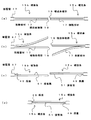
本発明では、この接着面積を容易に確保するため、以下のようにして補強条15同士を接合する。図6は、補強条15の接合工程を示す図である。まず、図6(a)に示すように、接合したい補強条15の補強条端部19同士を対向させる。この際、剥離部材17が設けられる範囲の被覆層47は事前に剥離しておく。 In this invention, in order to ensure this adhesion area easily, the reinforcing strips 15 are joined as follows. FIG. 6 is a diagram illustrating a joining process of the reinforcing strip 15. First, as shown in FIG. 6A, the reinforcing strip end portions 19 of the reinforcing strip 15 to be joined are made to face each other. At this time, the covering layer 47 in a range where the peeling member 17 is provided is peeled off in advance.
次に、図6(b)に示すように、剥離部材17設置範囲において、それぞれの補強条15を厚さ方向に剥離する。剥離部材17は、補強条15の全幅に渡って形成されており、この部分ではマトリックス樹脂が一体化されていないため、容易に剥離することができる。 Next, as shown in FIG.6 (b), in the peeling member 17 installation range, each reinforcement strip 15 is peeled in the thickness direction. The peeling member 17 is formed over the entire width of the reinforcing strip 15, and since the matrix resin is not integrated in this portion, the peeling member 17 can be easily peeled off.
次に、図6(c)に示すように、補強条15の剥離された部位(の一部)を切除する。この際、一方の側(例えば巻きつけられた補強条の後端)は、表面側の剥離部を切除し、他方の側(例えば新たに巻きつける補強条の先端)は、裏面側の剥離部を切除する。補強条を厚さ方向に剥離し、剥離部を切除することで、補強条15には、厚さ方向に段差49が形成される。すなわち、接合する補強条同士の一方の側は表面側に段差49が形成され、他方の側は裏面側に段差49が形成される。なお、この際、剥離部材17は撤去される。また、それぞれの補強条15の段差が形成される側における剥離部(補強条の長手方向に垂直な方向の面)が接着面51となる。 Next, as shown in FIG.6 (c), the site | part (part of) from which the reinforcing strip 15 was peeled is excised. At this time, one side (for example, the rear end of the wound reinforcing strip) cuts off the peeling portion on the front surface side, and the other side (for example, the front end of the newly wound reinforcing strip) has the peeling portion on the back side. Excise. A step 49 is formed in the reinforcing strip 15 in the thickness direction by peeling the reinforcing strip in the thickness direction and cutting off the peeled portion. That is, a step 49 is formed on the front side of one side of the reinforcing strips to be joined, and a step 49 is formed on the back side of the other side. At this time, the peeling member 17 is removed. Further, the peeled portion (the surface in the direction perpendicular to the longitudinal direction of the reinforcing strip) on the side where the step of each reinforcing strip 15 is formed becomes the adhesive surface 51.
次に、図6(d)に示すように、それぞれの接着面51に接着剤(例えばエポキシ系接着剤)を塗布し、接着面同士を対向させて接着する。すなわち、それぞれの段差49同士が重ね合わされて接着面51で接着される。接着面51は、補強条15の厚さの略中央に設けられるため、接着部における補強条の厚さは、接着部以外の部位の補強条15と略同等である。 Next, as shown in FIG. 6 (d), an adhesive (for example, an epoxy-based adhesive) is applied to each of the adhesive surfaces 51, and the adhesive surfaces are bonded to face each other. That is, the respective steps 49 are overlapped and bonded by the bonding surface 51. Since the bonding surface 51 is provided at substantially the center of the thickness of the reinforcing strip 15, the thickness of the reinforcing strip in the bonded portion is substantially the same as that of the reinforcing strip 15 other than the bonded portion.
以上により、補強条15が長手方向に接合されて巻きつけられ、可撓管1が製造される。なお、前述の通り、複数の補強条15が同一外周面に巻きつけられるが、補強条同士の接合部が、可撓管の長手方向で同一場所とならないようにすることが望ましい。すなわち、補強条同士の接合部は、可撓管1の長手方向に分散されることが望ましい。
As described above, the reinforcing strip 15 is joined and wound in the longitudinal direction, and the
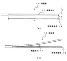
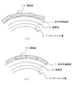
また、補強条15を巻きつける際、補強条15の端部が内周面に密着せずに浮き上がる恐れがある。図7(a)は、補強条15を耐内圧補強層7の外周に巻き付けた際の断面模式図である。補強条15は繊維強化ブラスチック製であり、剛性が高いため、巻きつける内周面(耐内圧補強層の外周面)の円弧状の面に沿って巻きつけることが困難である。 Further, when the reinforcing strip 15 is wound, the end portion of the reinforcing strip 15 may be lifted without being in close contact with the inner peripheral surface. FIG. 7A is a schematic cross-sectional view when the reinforcing strip 15 is wound around the outer periphery of the internal pressure-proof reinforcing layer 7. Since the reinforcing strip 15 is made of fiber reinforced plastic and has high rigidity, it is difficult to wind along the arcuate surface of the inner peripheral surface to be wound (the outer peripheral surface of the internal pressure-proof reinforcing layer).
補強条15を構成する繊維強化プラスチックのマトリックス樹脂として熱可塑性樹脂を用い、巻きつけ時に補強条を熱風等で加熱し、軟化した状態で巻き付けることで、図7(b)に示すように、巻きつけ面の円弧状に沿って補強条15を変形させて巻きつけることができる。なお、補強条15はその後の冷却時により硬化して所定強度を発現することができる。また、前述した補強条同士の接合時においても、剥離作業等において加熱すれば、接合作業がより容易となる。 As shown in FIG. 7 (b), a thermoplastic resin is used as the matrix resin of the fiber reinforced plastic constituting the reinforcing strip 15, and the reinforcing strip is heated with hot air or the like at the time of winding and wound in a softened state. The reinforcing strip 15 can be deformed and wound along the arcuate shape of the attaching surface. The reinforcing strip 15 can be hardened by the subsequent cooling and exhibit a predetermined strength. Further, even when the reinforcing strips are joined to each other, if the heating is performed in a peeling operation or the like, the joining operation becomes easier.
以上、本実施の形態によれば、軸力補強層9を構成する補強条15として、繊維強化プラスチック製の補強条を用いるため、軽量であり耐食性に優れる。また、補強条15同士の接合部においては、剥離部材17が設けられるため、必要な接合強度を確保できるだけの接着面積を容易に形成することができ、補強条15の断面形状が変化することもない。 As mentioned above, according to this Embodiment, since the reinforcing strip made from a fiber reinforced plastic is used as the reinforcing strip 15 which comprises the axial force reinforcement layer 9, it is lightweight and is excellent in corrosion resistance. In addition, since the peeling member 17 is provided at the joint between the reinforcing strips 15, a bonding area sufficient to ensure the necessary joint strength can be easily formed, and the cross-sectional shape of the reinforcing strip 15 may change. Absent.
また、補強条15の製造は、複数の補強繊維集合体43に分けてその間に剥離部材17を挿入すればよいため、製造が容易である。また、補強条15の周囲に被覆層47が設けられるため、補強条15の摩耗や破損等を防止することができる。 Further, the manufacture of the reinforcing strips 15 is easy because the reinforcing strips 15 can be divided into a plurality of reinforcing fiber assemblies 43 and the peeling member 17 inserted between them. Moreover, since the coating layer 47 is provided around the reinforcing strip 15, it is possible to prevent the reinforcing strip 15 from being worn or damaged.
また、剥離部材17が厚さの50倍以上の範囲に設けられることで、接着面積として幅x厚さの50倍以上を確保することができ、十分な接合強度を得ることができる。 Moreover, by providing the peeling member 17 in the range of 50 times or more of the thickness, it is possible to ensure 50 times or more of the width x thickness as the bonding area, and to obtain sufficient bonding strength.
また、補強条15のマトリックス樹脂が熱可塑性樹脂であるため、補強条15を巻きつける際に、補強条15を巻きつけ面の円弧状に変形させ、巻きつけ面に密着させることができる。 Further, since the matrix resin of the reinforcing strip 15 is a thermoplastic resin, when the reinforcing strip 15 is wound, the reinforcing strip 15 can be deformed into an arc shape of the winding surface and can be brought into close contact with the winding surface.
以上、添付図を参照しながら、本発明の実施の形態を説明したが、本発明の技術的範囲は、前述した実施の形態に左右されない。当業者であれば、特許請求の範囲に記載された技術的思想の範疇内において各種の変更例または修正例に想到し得ることは明らかであり、それらについても当然に本発明の技術的範囲に属するものと了解される。 As mentioned above, although embodiment of this invention was described referring an accompanying drawing, the technical scope of this invention is not influenced by embodiment mentioned above. It is obvious for those skilled in the art that various modifications or modifications can be conceived within the scope of the technical idea described in the claims, and these are naturally within the technical scope of the present invention. It is understood that it belongs.
1………可撓管
3………インターロック管
5………遮蔽層
7………耐内圧補強層
9………軸力補強層
11………シース層
13a、13b、13c、13d………座床層
15、60………補強条
17………剥離部材
19………補強条端部
21………補強条製造装置
23………補強繊維コイル
25a、25b………補強繊維集合体整形機
27………引取機
29………剥離部材供給機
31e………樹脂供給・硬化装置
33………冷却機
35………被覆装置
37………整形装置
39………補強条巻き取り機
41………補強繊維
43………補強繊維集合体
45………樹脂
47………被覆層
49………段差
51、61、67………接着面
63………かしめ部材
65………テーパ部
DESCRIPTION OF
Claims (8)
前記補強条は、繊維強化プラスチック製の帯状部材であり、
前記補強条の端部近傍の内部には剥離部材が設けられ、前記補強条の端部は厚さ方向に剥離可能であることを特徴とする補強条。 A reinforcing strip used for an axial force reinforcing layer of a flexible pipe for fluid transportation,
The reinforcing strip is a belt-shaped member made of fiber reinforced plastic,
A reinforcing strip is provided inside the vicinity of the end of the reinforcing strip, and the end of the reinforcing strip is peelable in the thickness direction.
可撓性を有する管体と、
前記管体の外周部に設けられた遮蔽層と、
前記遮蔽層の外周部に設けられた耐内圧補強層と、
前記耐内圧補強層の外周部に設けられた軸力補強層と、
前記軸力補強層の外周部に設けられたシース層と、
を具備し、
前記軸力補強層は、前記補強条が前記耐内圧補強層の周方向に複数配置され、前記耐内圧補強層の外周部に螺旋状に巻き付けられ、さらに前記補強条が長手方向に複数接合されることで形成され、
前記補強条の端部の前記剥離部材の設けられる範囲が、厚さ方向に剥離され、剥離された部位が切除されることで前記補強条の端部には段差が形成されており、
前記補強条の長手方向に対向するそれぞれの前記段差が重ね合わされ、前記補強条の長手方向に略垂直な方向の面同士が接着されることで、前記補強条が長手方向に複数接合されることを特徴とする流体輸送用可撓管。 A flexible pipe for transporting fluid using the reinforcing strip according to any one of claims 1 to 3,
A flexible tube;
A shielding layer provided on the outer periphery of the tubular body;
An internal pressure-proof reinforcing layer provided on the outer periphery of the shielding layer;
An axial force reinforcing layer provided on an outer peripheral portion of the internal pressure resistant reinforcing layer;
A sheath layer provided on the outer periphery of the axial force reinforcing layer;
Comprising
In the axial force reinforcing layer, a plurality of the reinforcing strips are arranged in the circumferential direction of the internal pressure-resistant reinforcing layer, are wound spirally around the outer peripheral portion of the internal pressure-resistant reinforcing layer, and a plurality of the reinforcing strips are joined in the longitudinal direction. Formed by
The range where the peeling member is provided at the end of the reinforcing strip is peeled off in the thickness direction, and a step is formed at the end of the reinforcing strip by excising the peeled site.
The steps opposite to each other in the longitudinal direction of the reinforcing strips are overlapped, and surfaces in a direction substantially perpendicular to the longitudinal direction of the reinforcing strips are bonded to each other, whereby a plurality of the reinforcing strips are joined in the longitudinal direction. A flexible tube for transporting fluid.
複数の繊維部材を複数のグループに分けて集合して複数の繊維部材集合体を形成し、複数の前記繊維部材集合体の先端部および後端部において、複数の前記繊維部材集合体の間に剥離部材を挿入し、複数の前記繊維部材集合体を一体化するように樹脂を供給して帯状の繊維強化ブラスチックを形成することを特徴とする補強条の製造方法。 A method of manufacturing a reinforcing strip used for an axial force reinforcing layer of a flexible tube for fluid transportation,
A plurality of fiber members are grouped into a plurality of groups to form a plurality of fiber member aggregates, and between the plurality of fiber member aggregates at the front end portion and the rear end portion of the plurality of fiber member aggregates. A method for producing a reinforcing strip, wherein a strip-like fiber-reinforced plastic is formed by inserting a release member and supplying a resin so as to integrate the plurality of fiber member assemblies.
先端および後端における内部に、厚さ方向に剥離可能な剥離部材が設けられた繊維強化プラスチック製の補強条を用い、
可撓性を有する管体の周囲に樹脂を押し出し被覆して遮蔽層を形成する工程と、
前記遮蔽層の外周に耐内圧用補強条を短ピッチで巻き付けて耐内圧補強層を形成する工程と、
前記耐内圧補強層の外周に、複数の前記補強条を周方向に並列した状態から長ピッチで巻き付けて軸力補強層を形成する工程と、
前記軸力補強層の外周にシースを押出し被覆してシース層を形成する工程と、
を具備し、
前記補強条の巻き付けの際、長手方向に接合される1対の補強条の対向するそれぞれの先端部および後端部において、前記剥離部材によって前記補強条を厚さ方向に剥離し、剥離された部位を切除することでそれぞれ段差を形成し、
一対の前記補強条の前記段差同士を重ね合わせ、前記補強条の長手方向に略垂直な方向の面同士を接着して接合することを特徴とする流体輸送用可撓管の製造方法。 A method for producing a flexible tube for fluid transportation, comprising:
Using a reinforcing strip made of fiber reinforced plastic provided with a peeling member capable of peeling in the thickness direction inside the front and rear ends,
Forming a shielding layer by extruding and coating a resin around a flexible tube; and
A step of forming an internal pressure-resistant reinforcing layer by winding an internal pressure-resistant reinforcing strip at a short pitch around the outer periphery of the shielding layer;
A process of forming an axial force reinforcing layer by winding a plurality of the reinforcing strips at a long pitch from a state in which the plurality of reinforcing strips are juxtaposed in the circumferential direction on the outer periphery of the internal pressure resistant reinforcing layer;
Forming a sheath layer by extruding and covering the outer periphery of the axial force reinforcing layer; and
Comprising
At the time of winding of the reinforcing strip, the reinforcing strip was peeled off in the thickness direction by the peeling member at each of the opposing front end portion and rear end portion of the pair of reinforcing strips joined in the longitudinal direction. By excising the part, each step is formed,
A method for producing a flexible tube for transporting fluid, characterized in that the steps of a pair of reinforcing strips are overlapped, and surfaces in a direction substantially perpendicular to the longitudinal direction of the reinforcing strips are bonded and joined together.
前記補強条を前記耐内圧補強層の外周に巻きつける際、前記補強条を加熱して軟化させ、前記補強条が巻きつけられる円弧状の面に沿って前記補強条を変形させることを特徴とする請求項7記載の流体輸送用可撓管の製造方法。 The reinforcing strip is a fiber reinforced plastic having a thermosetting resin as a matrix,
When the reinforcing strip is wound around the outer periphery of the internal pressure-proof reinforcing layer, the reinforcing strip is heated and softened, and the reinforcing strip is deformed along an arcuate surface around which the reinforcing strip is wound. A method for manufacturing a flexible tube for fluid transportation according to claim 7.
Priority Applications (1)
| Application Number | Priority Date | Filing Date | Title |
|---|---|---|---|
| JP2009245189A JP5367532B2 (en) | 2009-10-26 | 2009-10-26 | Reinforcing strip, flexible tube for transporting fluid, method for manufacturing reinforcing strip, and manufacturing method of flexible tube for transporting fluid |
Applications Claiming Priority (1)
| Application Number | Priority Date | Filing Date | Title |
|---|---|---|---|
| JP2009245189A JP5367532B2 (en) | 2009-10-26 | 2009-10-26 | Reinforcing strip, flexible tube for transporting fluid, method for manufacturing reinforcing strip, and manufacturing method of flexible tube for transporting fluid |
Publications (2)
| Publication Number | Publication Date |
|---|---|
| JP2011089616A JP2011089616A (en) | 2011-05-06 |
| JP5367532B2 true JP5367532B2 (en) | 2013-12-11 |
Family
ID=44108043
Family Applications (1)
| Application Number | Title | Priority Date | Filing Date |
|---|---|---|---|
| JP2009245189A Expired - Fee Related JP5367532B2 (en) | 2009-10-26 | 2009-10-26 | Reinforcing strip, flexible tube for transporting fluid, method for manufacturing reinforcing strip, and manufacturing method of flexible tube for transporting fluid |
Country Status (1)
| Country | Link |
|---|---|
| JP (1) | JP5367532B2 (en) |
Families Citing this family (1)
| Publication number | Priority date | Publication date | Assignee | Title |
|---|---|---|---|---|
| JP5777971B2 (en) * | 2011-08-10 | 2015-09-16 | 古河電気工業株式会社 | Flexible tube for fluid transportation and method for manufacturing flexible tube for fluid transportation |
Family Cites Families (4)
| Publication number | Priority date | Publication date | Assignee | Title |
|---|---|---|---|---|
| JPH02134483A (en) * | 1988-11-14 | 1990-05-23 | Shiro Kanao | Spiral waveform pipe of hard pvc |
| JPH05296371A (en) * | 1992-04-22 | 1993-11-09 | Toyoda Gosei Co Ltd | Reinforcing hose |
| JP4297359B2 (en) * | 2004-09-10 | 2009-07-15 | 古河電気工業株式会社 | Pooling terminal for laying flexible fluid transport pipe |
| JP2006175602A (en) * | 2004-12-20 | 2006-07-06 | Toyo Tire & Rubber Co Ltd | Manufacturing method of fiber-reinforced rubber molded body |
-
2009
- 2009-10-26 JP JP2009245189A patent/JP5367532B2/en not_active Expired - Fee Related
Also Published As
| Publication number | Publication date |
|---|---|
| JP2011089616A (en) | 2011-05-06 |
Similar Documents
| Publication | Publication Date | Title |
|---|---|---|
| EP3721125B1 (en) | High-pressure pipe with pultruded elements and method for producing the same | |
| JP6087420B2 (en) | Multi-layer pipeline including polymer material, apparatus for manufacturing multi-layer pipeline, and method for manufacturing multi-layer pipeline | |
| JP4465136B2 (en) | Tubular liner comprising a tubular film coated with nonwoven fabric | |
| JP4163385B2 (en) | Composite high-pressure pipe and joining method thereof | |
| CN108286627B (en) | Thermoplastic composite tube with multi-layer middle sheet layer | |
| JPWO2000022334A1 (en) | Composite high-pressure pipe and its joining method | |
| WO2011060695A1 (en) | Steel strip reinforced composite belt for helically corrugated plastic-steel winding pipe | |
| JP2018111310A (en) | Thermoplastic composite pipe with multilayer intermediate lamina | |
| JP5367532B2 (en) | Reinforcing strip, flexible tube for transporting fluid, method for manufacturing reinforcing strip, and manufacturing method of flexible tube for transporting fluid | |
| JP5255477B2 (en) | Method for manufacturing flexible tube for fluid transportation | |
| CN106068179A (en) | Composite material pipe and production method therefor | |
| JPH11235758A (en) | Manufacturing method of pipe lining material and pipe lining method | |
| JP6954798B2 (en) | Laminated body for pipe rehabilitation and member for pipe rehabilitation | |
| JPH11264488A (en) | Fluid impermeable composite hose | |
| JP5503624B2 (en) | Reinforcing structure, reinforcing method, and reinforcing member for connecting portion of resin reinforcing pipe | |
| CN220647062U (en) | Electric melting pipe fitting with continuous steel fiber band reinforced multilayer composite structure and production system | |
| JP2005016580A (en) | Synthetic resin pipe | |
| JP3994432B2 (en) | Low permeation hose and manufacturing method thereof | |
| US20250170793A1 (en) | Method for producing a flexible composite pipe, and thermoplastic composite pipe | |
| JP4850036B2 (en) | Method for manufacturing elastic hose | |
| BR112020010052B1 (en) | FLEXIBLE HIGH PRESSURE PIPE AND METHOD FOR PRODUCING A FLEXIBLE HIGH PRESSURE PIPE | |
| JP2005016579A (en) | Synthetic resin pipe | |
| JP2008267430A (en) | Flexible laminated hose | |
| WO2025032260A1 (en) | Lined pipelines | |
| CN114893626A (en) | Fiber-overlapped reinforced plastic composite winding pipe wall, pipe and manufacturing method |
Legal Events
| Date | Code | Title | Description |
|---|---|---|---|
| A621 | Written request for application examination |
Free format text: JAPANESE INTERMEDIATE CODE: A621 Effective date: 20120601 |
|
| TRDD | Decision of grant or rejection written | ||
| A01 | Written decision to grant a patent or to grant a registration (utility model) |
Free format text: JAPANESE INTERMEDIATE CODE: A01 Effective date: 20130820 |
|
| A61 | First payment of annual fees (during grant procedure) |
Free format text: JAPANESE INTERMEDIATE CODE: A61 Effective date: 20130911 |
|
| R151 | Written notification of patent or utility model registration |
Ref document number: 5367532 Country of ref document: JP Free format text: JAPANESE INTERMEDIATE CODE: R151 |
|
| LAPS | Cancellation because of no payment of annual fees |