JP5366145B2 - Battery including fluid management mechanism mounted outside the cell - Google Patents
Battery including fluid management mechanism mounted outside the cell Download PDFInfo
- Publication number
- JP5366145B2 JP5366145B2 JP2009505592A JP2009505592A JP5366145B2 JP 5366145 B2 JP5366145 B2 JP 5366145B2 JP 2009505592 A JP2009505592 A JP 2009505592A JP 2009505592 A JP2009505592 A JP 2009505592A JP 5366145 B2 JP5366145 B2 JP 5366145B2
- Authority
- JP
- Japan
- Prior art keywords
- fluid
- cell
- plate
- chassis
- valve
- Prior art date
- Legal status (The legal status is an assumption and is not a legal conclusion. Google has not performed a legal analysis and makes no representation as to the accuracy of the status listed.)
- Expired - Fee Related
Links
Images


Classifications
-
- H—ELECTRICITY
- H01—ELECTRIC ELEMENTS
- H01M—PROCESSES OR MEANS, e.g. BATTERIES, FOR THE DIRECT CONVERSION OF CHEMICAL ENERGY INTO ELECTRICAL ENERGY
- H01M12/00—Hybrid cells; Manufacture thereof
- H01M12/04—Hybrid cells; Manufacture thereof composed of a half-cell of the fuel-cell type and of a half-cell of the primary-cell type
- H01M12/06—Hybrid cells; Manufacture thereof composed of a half-cell of the fuel-cell type and of a half-cell of the primary-cell type with one metallic and one gaseous electrode
-
- H—ELECTRICITY
- H01—ELECTRIC ELEMENTS
- H01M—PROCESSES OR MEANS, e.g. BATTERIES, FOR THE DIRECT CONVERSION OF CHEMICAL ENERGY INTO ELECTRICAL ENERGY
- H01M50/00—Constructional details or processes of manufacture of the non-active parts of electrochemical cells other than fuel cells, e.g. hybrid cells
- H01M50/10—Primary casings, jackets or wrappings of a single cell or a single battery
- H01M50/102—Primary casings, jackets or wrappings of a single cell or a single battery characterised by their shape or physical structure
- H01M50/103—Primary casings, jackets or wrappings of a single cell or a single battery characterised by their shape or physical structure prismatic or rectangular
-
- H—ELECTRICITY
- H01—ELECTRIC ELEMENTS
- H01M—PROCESSES OR MEANS, e.g. BATTERIES, FOR THE DIRECT CONVERSION OF CHEMICAL ENERGY INTO ELECTRICAL ENERGY
- H01M50/00—Constructional details or processes of manufacture of the non-active parts of electrochemical cells other than fuel cells, e.g. hybrid cells
- H01M50/10—Primary casings, jackets or wrappings of a single cell or a single battery
- H01M50/138—Primary casings, jackets or wrappings of a single cell or a single battery adapted for specific cells, e.g. electrochemical cells operating at high temperature
- H01M50/1385—Hybrid cells
-
- H—ELECTRICITY
- H01—ELECTRIC ELEMENTS
- H01M—PROCESSES OR MEANS, e.g. BATTERIES, FOR THE DIRECT CONVERSION OF CHEMICAL ENERGY INTO ELECTRICAL ENERGY
- H01M50/00—Constructional details or processes of manufacture of the non-active parts of electrochemical cells other than fuel cells, e.g. hybrid cells
- H01M50/30—Arrangements for facilitating escape of gases
- H01M50/317—Re-sealable arrangements
- H01M50/325—Re-sealable arrangements comprising deformable valve members, e.g. elastic or flexible valve members
-
- H—ELECTRICITY
- H01—ELECTRIC ELEMENTS
- H01M—PROCESSES OR MEANS, e.g. BATTERIES, FOR THE DIRECT CONVERSION OF CHEMICAL ENERGY INTO ELECTRICAL ENERGY
- H01M50/00—Constructional details or processes of manufacture of the non-active parts of electrochemical cells other than fuel cells, e.g. hybrid cells
- H01M50/30—Arrangements for facilitating escape of gases
- H01M50/394—Gas-pervious parts or elements
-
- H—ELECTRICITY
- H01—ELECTRIC ELEMENTS
- H01M—PROCESSES OR MEANS, e.g. BATTERIES, FOR THE DIRECT CONVERSION OF CHEMICAL ENERGY INTO ELECTRICAL ENERGY
- H01M8/00—Fuel cells; Manufacture thereof
- H01M8/04—Auxiliary arrangements, e.g. for control of pressure or for circulation of fluids
- H01M8/04082—Arrangements for control of reactant parameters, e.g. pressure or concentration
- H01M8/04089—Arrangements for control of reactant parameters, e.g. pressure or concentration of gaseous reactants
-
- H—ELECTRICITY
- H01—ELECTRIC ELEMENTS
- H01M—PROCESSES OR MEANS, e.g. BATTERIES, FOR THE DIRECT CONVERSION OF CHEMICAL ENERGY INTO ELECTRICAL ENERGY
- H01M8/00—Fuel cells; Manufacture thereof
- H01M8/04—Auxiliary arrangements, e.g. for control of pressure or for circulation of fluids
- H01M8/04298—Processes for controlling fuel cells or fuel cell systems
- H01M8/04694—Processes for controlling fuel cells or fuel cell systems characterised by variables to be controlled
- H01M8/04746—Pressure; Flow
- H01M8/04753—Pressure; Flow of fuel cell reactants
-
- Y—GENERAL TAGGING OF NEW TECHNOLOGICAL DEVELOPMENTS; GENERAL TAGGING OF CROSS-SECTIONAL TECHNOLOGIES SPANNING OVER SEVERAL SECTIONS OF THE IPC; TECHNICAL SUBJECTS COVERED BY FORMER USPC CROSS-REFERENCE ART COLLECTIONS [XRACs] AND DIGESTS
- Y02—TECHNOLOGIES OR APPLICATIONS FOR MITIGATION OR ADAPTATION AGAINST CLIMATE CHANGE
- Y02E—REDUCTION OF GREENHOUSE GAS [GHG] EMISSIONS, RELATED TO ENERGY GENERATION, TRANSMISSION OR DISTRIBUTION
- Y02E60/00—Enabling technologies; Technologies with a potential or indirect contribution to GHG emissions mitigation
- Y02E60/10—Energy storage using batteries
-
- Y—GENERAL TAGGING OF NEW TECHNOLOGICAL DEVELOPMENTS; GENERAL TAGGING OF CROSS-SECTIONAL TECHNOLOGIES SPANNING OVER SEVERAL SECTIONS OF THE IPC; TECHNICAL SUBJECTS COVERED BY FORMER USPC CROSS-REFERENCE ART COLLECTIONS [XRACs] AND DIGESTS
- Y02—TECHNOLOGIES OR APPLICATIONS FOR MITIGATION OR ADAPTATION AGAINST CLIMATE CHANGE
- Y02E—REDUCTION OF GREENHOUSE GAS [GHG] EMISSIONS, RELATED TO ENERGY GENERATION, TRANSMISSION OR DISTRIBUTION
- Y02E60/00—Enabling technologies; Technologies with a potential or indirect contribution to GHG emissions mitigation
- Y02E60/30—Hydrogen technology
- Y02E60/50—Fuel cells
-
- Y—GENERAL TAGGING OF NEW TECHNOLOGICAL DEVELOPMENTS; GENERAL TAGGING OF CROSS-SECTIONAL TECHNOLOGIES SPANNING OVER SEVERAL SECTIONS OF THE IPC; TECHNICAL SUBJECTS COVERED BY FORMER USPC CROSS-REFERENCE ART COLLECTIONS [XRACs] AND DIGESTS
- Y10—TECHNICAL SUBJECTS COVERED BY FORMER USPC
- Y10T—TECHNICAL SUBJECTS COVERED BY FORMER US CLASSIFICATION
- Y10T29/00—Metal working
- Y10T29/49—Method of mechanical manufacture
- Y10T29/49002—Electrical device making
- Y10T29/49108—Electric battery cell making
Abstract
Description
〔関連出願の説明〕
本出願は、2006年4月11日に出願された米国仮特許出願第60/790,876号、2006年6月28日に出願された米国仮特許出願第60/817,199号、及び2006年11月20日に出願された米国仮特許出願第60/860,175号の利益を主張し、上記出願の各々の開示全体は引用により本明細書に組み込まれる。
[Description of related applications]
This application includes US Provisional Patent Application No. 60 / 790,876 filed on April 11, 2006, US Provisional Patent Application No. 60 / 817,199 filed on June 28, 2006, and 2006. Claiming the benefit of US Provisional Patent Application No. 60 / 860,175, filed Nov. 20, 2011, the entire disclosure of each of the above applications is incorporated herein by reference.
本発明は、流体消費電極を備えた電気化学電池及びセルに出入りするガスなどの流体の流入速度を制御するための流体調整システムに関し、更に、このような流体調整システムが使用される電池及びセル、具体的には、空気減極型、空気補助型、並びに燃料セル及び電池に関する。 The present invention relates to an electrochemical battery equipped with a fluid consuming electrode and a fluid regulating system for controlling the inflow speed of a fluid such as a gas entering and leaving the cell, and further to the battery and the cell in which such a fluid regulating system is used. Specifically, the present invention relates to an air depolarization type, an air auxiliary type, and a fuel cell and a battery.
空気減極型、空気補助型、並びに燃料電池の電池セルのような、電気エネルギを発生させるための活物質としてセルの外部から酸素及び他のガスのような流体を使用する電気化学電池セルを用いて、様々な携帯用電子機器に電力を供給することができる。例えば、空気は、空気減極型又は空気補助型セルに入り、そこで正電極活物質として用いるか、又はこれを再充電することができる。酸素還元電極は、酸素とセル電解質との反応を促進し、最終的には負電極活物質の酸素による酸化を促進する。酸素と電解質との反応を促進する酸素還元電極内の材料は、触媒と呼ばれることが多い。しかしながら、酸素還元電極に使用される一部の材料は、特に比較的高率の放電期間中に少なくとも部分的に還元可能であるので、真の触媒ではない。 Electrochemical battery cells that use fluids such as oxygen and other gases from the outside of the cell as active materials for generating electrical energy, such as air depolarized, air-assisted, and fuel cell batteries It can be used to supply power to various portable electronic devices. For example, air can enter an air depolarized or air assisted cell where it can be used as a positive electrode active material or it can be recharged. The oxygen reduction electrode promotes the reaction between oxygen and the cell electrolyte, and finally promotes the oxidation of the negative electrode active material by oxygen. The material in the oxygen reduction electrode that promotes the reaction between oxygen and the electrolyte is often referred to as a catalyst. However, some materials used for oxygen reduction electrodes are not true catalysts because they can be at least partially reduced, especially during relatively high rate discharge periods.
空気減極型セルの種類の1つは、亜鉛/エアセルである。この種類のセルは、負電極活物質として亜鉛を使用し、水性アルカリ(例えば、KOH)電解質を有する。亜鉛/エアセルの空気内で使用することができる酸化マンガンは、特に、酸素の空気電極内への拡散速度が十分でないときは、負電極活物質の酸化に呼応して電気化学的に還元することができる。次に、これらの酸化マンガンは、より低率の放電又は休止期間中に酸素によって再酸化することができる。 One type of air depolarized cell is a zinc / air cell. This type of cell uses zinc as the negative electrode active material and has an aqueous alkaline (eg, KOH) electrolyte. Manganese oxide that can be used in the air of zinc / air cells should be reduced electrochemically in response to oxidation of the negative electrode active material, especially when the diffusion rate of oxygen into the air electrode is not sufficient. Can do. These manganese oxides can then be reoxidized with oxygen during a lower rate of discharge or rest periods.
空気補助型セルは、消費可能な正電極及び負電極活物質並びに酸素還元電極を含むハイブリッドセルである。正電極は、相当な期間にわたって高い放電率を維持することができるが、酸素は、酸素還元電極を通して低放電率又は無放電期間中は正電極を部分的に再充電することができ、よって、酸素は総セル放電容量の実質的な部分に使用することができる。これは、セル内に入れる正電極活物質の量を低減でき、負電極活物質の量を増大させて総セル容量を増大させることができることを意味する。空気補助型セルの実施例が、同一出願人による米国特許第6,383,674号及び第5,079,106号に開示されている。 An air-assisted cell is a hybrid cell that includes consumable positive and negative electrode active materials and an oxygen reduction electrode. The positive electrode can maintain a high discharge rate for a considerable period, but oxygen can partially recharge the positive electrode through the oxygen reduction electrode during a low discharge rate or no discharge period, thus Oxygen can be used for a substantial portion of the total cell discharge capacity. This means that the amount of positive electrode active material placed in the cell can be reduced, and the amount of negative electrode active material can be increased to increase the total cell capacity. Examples of air assisted cells are disclosed in commonly assigned US Pat. Nos. 6,383,674 and 5,079,106.
空気減極型、空気補助型及び燃料セルの利点は、電極の少なくとも1つの活物質の少なくとも一部分が、セルの外部からもたらされるか、又はセルの外部からの流体(例えば、ガス)によって再生されることに起因して、これらのエネルギ密度が高いことである。 The advantages of air depolarized, air assisted and fuel cells are that at least a portion of at least one active material of the electrode is brought from outside the cell or regenerated by a fluid (eg, gas) from outside the cell. This is because these energy densities are high.
これらのセルの欠点は、酸素が酸素還元電極に流入することができる速度によって、これらのセルが達成可能な最大放電率が制限される可能性がある点である。過去には、酸素還元電極に入る酸素流入速度を増大させ、及び/又は無駄な反応を引き起こす可能性のある二酸化炭素などの望ましくないガスの流入速度、並びに増大した容積の放電反応生成物を収容するか又はセルを完全に乾燥させることをそれぞれ意図したセル内の空隙を充填することができる水の流入速度又は損失率(セルの内外の相対的な水蒸気分圧に依存する)を制御する努力が注がれてきた。これらの手法の実施例には、米国特許第6,558,828号、米国特許第6,492,046号、米国特許第5,795,667号、米国特許第5,733,676号、米国特許出願公開第2002/0150814号、及び国際特許公開WO02/35641号に見出すことができる。しかしながら、これらのガスの1つの拡散率を変えると、一般に、他のものにも影響する。酸素の高い拡散率とCO2及び水の低い拡散率に対する必要性のバランスをとる努力がなされてきた場合でさえも、限定的な成功しか得られなかった。 The disadvantage of these cells is that the rate at which oxygen can flow into the oxygen reduction electrode can limit the maximum discharge rate that these cells can achieve. In the past, it accommodated an increased flow rate of undesired gases, such as carbon dioxide, which could increase the rate of oxygen flow into the oxygen reduction electrode and / or cause a useless reaction, and an increased volume of discharge reaction products. To control the rate of water inflow or loss (depending on the relative water vapor pressure inside and outside the cell) that can fill the voids in the cell, each intended to dry or completely dry the cell Has been poured. Examples of these techniques include US Pat. No. 6,558,828, US Pat. No. 6,492,046, US Pat. No. 5,795,667, US Pat. No. 5,733,676, US It can be found in Patent Application Publication No. 2002/0150814 and International Patent Publication No. WO 02/35641. However, changing the diffusivity of one of these gases generally affects the others. Even when efforts have been made to balance the need for high oxygen diffusivities and low CO 2 and water diffusivities, limited success has been achieved.
より高い放電率では、酸素還元電極内に十分な酸素を取り込むことがより重要であるが、低い放電率の期間及びセルが使用されていない期間中は、CO2及び水の拡散を最小にすることがより重要になる。高い放電率の期間の間だけセル内への空気流を増大させるために、ファンを用いてセル内に空気を強制的に送ってきた(例えば、米国特許第6,500,575号)が、ファン及びこの制御装置により製造コスト及び複雑さが増す可能性があり、ファンは、マイクロファンであっても、個々のセル、複数のセル電池パック、及び装置内の貴重な容積を占有する可能性がある。 At higher discharge rates, it is more important to incorporate enough oxygen into the oxygen reduction electrode, but minimize CO 2 and water diffusion during periods of low discharge rate and when the cell is not in use. It becomes more important. In order to increase air flow into the cell only during periods of high discharge rates, fans have been used to force air into the cell (eg, US Pat. No. 6,500,575) The fan and this controller can add manufacturing cost and complexity, and even if the fan is a microfan, it can occupy individual cells, multiple cell battery packs, and valuable volume within the device There is.
提案されている別の手法は、バルブを使用してセルに流入する空気の量を制御する(例えば、米国特許第6,641,947号及び米国特許公開第2003/0186099号)ことであるが、バルブを作動させるために、ファン及び/又は比較的複雑な電子機器などの外部手段が必要である可能性がある。 Another proposed approach is to use valves to control the amount of air entering the cell (eg, US Pat. No. 6,641,947 and US Patent Publication No. 2003/0186099). In order to operate the valve, external means such as a fan and / or relatively complex electronics may be required.
更に別の手法は、例えば、電池が放電しているときの酸素の消費に起因する空気圧の差の結果として開閉することができるフラップを有する水不透過性膜を酸素還元電極と外部環境との間に用いることである(例えば、米国特許公開第2003/0049508号)。しかしながら、圧力差は小さい場合があり、電池外部の大気条件により影響を受ける可能性がある。 Yet another approach is to use a water-impermeable membrane with a flap that can be opened and closed as a result of, for example, a difference in air pressure due to the consumption of oxygen when the battery is discharging between the oxygen reduction electrode and the external environment. (For example, US Patent Publication No. 2003/0049508). However, the pressure difference may be small and may be affected by atmospheric conditions outside the battery.
同一出願人による米国特許公開第2005/0136321号は、バルブを開閉するために両端に印加された電位の変化に応答するアクチュエータによって動作するバルブを開示している。 US Patent Publication No. 2005/0136321 by the same applicant discloses a valve that is operated by an actuator that responds to changes in the potential applied across it to open and close the valve.
本発明の1つの態様によれば、内部に流体を通すための少なくとも1つの流体流入ポートを有するセルハウジングと、セルハウジング内に配置された第1の流体消費電極と、セルハウジング内に配置された第2の電極と、第1の流体消費電極に達するように少なくとも1つの流体流入ポートに流体を選択的に流入させることができるよう配置された流体調整システムとを備えた電池が提供される。流体調整システムは、セルハウジングの外側表面に隣接して配置され、少なくとも1つの流体流入ポートと整列して及び整列せずに移動するような少なくとも1つのプレートアパーチャを有する可動プレートと、加熱されたときに可動プレートを移動させるための形状記憶合金構成部品を有するアクチュエータとを含む。 According to one aspect of the present invention, a cell housing having at least one fluid inflow port for passing fluid therein, a first fluid consuming electrode disposed within the cell housing, and disposed within the cell housing. There is provided a battery with a second electrode and a fluid conditioning system arranged to allow fluid to selectively flow into the at least one fluid inlet port to reach the first fluid consuming electrode. . The fluid conditioning system is heated adjacent to the outer surface of the cell housing and has a movable plate having at least one plate aperture that moves in and out of alignment with the at least one fluid inlet port. And sometimes an actuator having a shape memory alloy component for moving the movable plate.
本発明の別の態様によれば、内部に流体を通すため側部を貫通させた少なくとも1つの流体流入ポートを有するセルハウジングと、セルハウジング内に配置された第1の流体消費電極と、セルハウジング内に配置された第2の電極と、第1の流体消費電極に達するように少なくとも1つの流体流入ポートに流体を選択的に流入させることができるよう配置された流体調整システムとを備えた電池が提供される。流体調整システムは、セルハウジングの外側表面に隣接して配置され、少なくとも1つの流体流入ポートと整列して及び整列せずに移動するような少なくとも1つのプレートアパーチャを有する可動プレートと、可動プレートを移動させるためのアクチュエータと、可動プレートを覆い、可動プレートへの流体通路を提供するリッドとを含む。 According to another aspect of the present invention, a cell housing having at least one fluid inflow port penetrating a side portion for allowing fluid to pass therethrough, a first fluid consumption electrode disposed in the cell housing, and a cell A second electrode disposed within the housing, and a fluid conditioning system disposed to selectively allow fluid to flow into the at least one fluid inlet port to reach the first fluid consuming electrode. A battery is provided. The fluid conditioning system is disposed adjacent to the outer surface of the cell housing and has a movable plate having at least one plate aperture that moves in alignment with and out of alignment with the at least one fluid inlet port; An actuator for movement and a lid that covers the movable plate and provides a fluid path to the movable plate.
本発明のこれら及び他の特徴、利点並びに目的は、以下の明細書、請求項の範囲及び添付図面を参照することにより当業者であれば更に理解し評価されるであろう。 These and other features, advantages and objects of the present invention will be further understood and appreciated by those skilled in the art by reference to the following specification, claims and appended drawings.
本発明の実施形態は、電極の1つに対する活物質としてセルの外側からの流体(酸素又は別のガスなど)を利用する電気化学セルを有する電池を含む。このセルは、酸素還元電極のような流体消費電極を有する。セルは、空気減極型セル、空気補助型セル又は燃料セルとすることができる。電池はまた、流体消費電極(例えば、空気減極型セル及び空気補助型セルの空気電極)への流体の通過速度を調節して、セルが高率又は高電力で放電するのにセルの外側から十分な流体量を提供し、同時に流体消費電極内への流体の流入と、低率放電又は無放電期間中のセルとの間の水分の増大又は減少とを最小にするための流体調節システムを有する。 Embodiments of the present invention include a battery having an electrochemical cell that utilizes a fluid (such as oxygen or another gas) from the outside of the cell as an active material for one of the electrodes. The cell has a fluid consuming electrode such as an oxygen reduction electrode. The cell can be an air depolarized cell, an air assisted cell or a fuel cell. The battery also adjusts the flow rate of fluid to fluid consuming electrodes (eg, air electrodes in air depolarized cells and air assisted cells) so that the cell can be discharged at a high rate or high power outside the cell. Fluid regulation system for providing a sufficient amount of fluid from the fluid and at the same time minimizing the inflow of fluid into the fluid consuming electrode and the increase or decrease of moisture between the cells during a low rate discharge or no discharge period Have
好ましくは、流体調整システムは、セル電位の変化に対する迅速な応答、長いサイクル寿命、放電時にセル電圧範囲に良好に適合する低作動電圧及び高効率を有することになる。これに加えて、この調整システムは、好ましくは、閉鎖位置において管理される流体に対する低透過性を有し、セル内の活性流体に対する必要性に応じて開閉し、極めて少量の全セル放電容量しか必要とせず、容積が小さく、製造及びセル内又はセル上への組み込みが容易で安価である。 Preferably, the fluid conditioning system will have a quick response to changes in cell potential, a long cycle life, a low operating voltage and a high efficiency that fits well into the cell voltage range during discharge. In addition, the conditioning system preferably has low permeability to the fluid managed in the closed position, opens and closes as needed for the active fluid in the cell, and has a very small total cell discharge capacity. It is not required, has a small volume, is easy and inexpensive to manufacture and incorporate in or on the cell.
別段の指示がなければ、本明細書で使用される用語「流体」とは、セルによる電気エネルギの生成の際に流体消費セルの流体消費電極によって消費することができる流体を意味する。本発明は、酸素還元電極を備えた空気減極型セルに関して以下で例証するが、本発明は、より一般的には、燃料電池のような他の種類の流体消費電極を有する流体消費セルで用いることができる。燃料セルは、セル電極の一方又は両方の活物質としてセルハウジングの外側からの様々なガスを使用することができる。 Unless otherwise indicated, the term “fluid” as used herein means a fluid that can be consumed by a fluid consuming electrode of a fluid consuming cell during the generation of electrical energy by the cell. Although the present invention is illustrated below with respect to an air depolarized cell with an oxygen reduction electrode, the present invention is more generally a fluid consuming cell having other types of fluid consuming electrodes, such as fuel cells. Can be used. The fuel cell can use various gases from the outside of the cell housing as the active material for one or both of the cell electrodes.
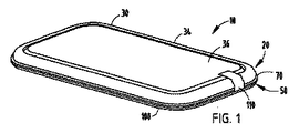
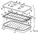
図1〜図3について以下で更に説明するように、本発明に従って構成された電池10は、流体消費セル20及び流体調整システム50を含む。流体調整システム50は、流体消費セル20の流体消費電極への流体の流れを調整する。空気減極型セルでは、流体調整システムは、流体消費セル20のセルハウジング30の内側又は外側で、且つ酸素還元電極の空気側に(すなわち、セルハウジングの外側からの空気に接触しやすい酸素還元電極の表面又は該表面の一部に)配置されている。
As further described below with respect to FIGS. 1-3, a
本発明に従って構成された電池10の第1の実施形態を図1〜図3に示している。図示のように、流体消費セル20(この場合には空気減極型セル)は、セルハウジング30を含み、該セルハウジングは、缶34及びカバー36をそれぞれ含むことができ、或いは、缶又はカバーとみなされるはずのものとは異なる形状又はサイズを有することができる、第1のハウジング構成部品及び第2のハウジング構成部品を含む。例示の目的で、第1のハウジング構成部品を以下では缶34と呼び、第2のハウジング構成部品を以下ではカバー36と呼ぶ。缶34及びカバー36は、両方とも導電性材料から作られるが、ガスケット38(図13)により互いに電気的に絶縁されている。缶34は、一般に、流体消費セル20の正の外部接触端子として機能を果たし、カバー36は、負の外部接触端子として機能を果たす。以下に更に説明するように、セル20は更に、流体消費電極又は空気電極とすることができる第1の電極40と、負電極(すなわち、アノード)とすることができる第2の電極42と、該第1及び第2の電極間に配置されたセパレータ44とを含む(図13参照)。第1の電極40は、好ましくは、缶34に電気的に結合され、第2の電極42は、好ましくは、カバー36に電気的に結合される。
A first embodiment of a
缶34は、流体がセルハウジング30の内部に移動して流体消費電極40に到達することができるように複数の流体流入ポート32が設けられた底面35を含む(図13参照)。
The
図1〜図3に示す実施形態において、流体調整システム50は、缶34の底面35の外側に固定される。流体調整システム50をセル20の外側に取り付けることができる特定の方法を以下で更に説明する。これに加えて、流体調整システム50を流体消費セル20の内側に組み込む別の実施形態を以下で説明する。
In the embodiment shown in FIGS. 1 to 3, the
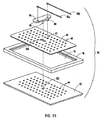
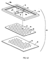
この特定の実施形態による流体調整システム50は、複数のアパーチャ64(流体流入ポート32に対応することができる)を有する第1のプレート62(缶34の底面35に対応することができる)と、第1のプレート62内に形成されたアパーチャ64にサイズ、形状、数及び位置で対応する複数のアパーチャ68を含む移動可能な第2のプレート66とを含むバルブ60を含むことができる。アパーチャ64及び68のサイズ、形状、数及び位置は、好ましくは、流体消費電極に適用される流体の所望の容積及び分布を提供するように最適化される。アパーチャ64のサイズ、形状、数及び相対位置は、アパーチャ68のサイズ、形状、数及び相対位置と同じである必要はない。例えば、アパーチャ64がアパーチャ68とわずかにサイズが異なる場合、プレート62及び66を通る最大合計開口面積を達成するために、アパーチャ64及び68の正確な位置合わせは重要ではない。
The
流体調整システム50は更に、第2のプレート66がその中に配置される開口74を備えた環状本体部分72を有するシャーシ70を含むことができる。開口74は、好ましくは、プレート66の細長い側端に接触すると同時に、プレート66が軸に沿ってその最長寸法と平行の軸線に沿って直線的に摺動できるようにプレート66の短い側部で過剰な空間を設けた形状及びサイズにされる。従って、図5A及び図5Bに示すように、第2のプレート66のアパーチャ68が、第1のプレート62のアパーチャ64と整列するように、及び整列しないように移動して、バルブ60を開放及び閉鎖することができる。シャーシは、好ましくは以下で説明するように、第1のプレート62に隣接して第2のプレート66を誘導するよう構成される。図5A及び図5Bに示すように、オイル又はTEFLON(登録商標)で作られた潤滑層69をプレート62及び66間に配置し、第2のプレート66がプレート62の表面に沿ってより容易に摺動できるようにすることができる。従って、潤滑層69により、アクチュエータによる力をほとんど必要とせずに、バルブを開閉することが可能になる。これに加えて、良好なシール性を得るためにはプレート62及び66の表面を十分に滑らかにすることが困難である可能性があるので、プレートの表面を更に滑らかにするための複雑で高価なプレート機構を必要とせずに、潤滑層69を利用してバルブのシール特性を高めることができる。第2のプレート66は、一般に冷蔵庫に設けられるガスケットに使用されているような、磁気材料で作ることができる。磁気プレート66を利用することによって、シャーシ70は、プレート66をプレート62に堅固に保持するための何からの機構を含めるように構成される必要はない。磁気プレート66は、好ましくは、隣接するプレート62の形状に共形にすることができる可撓性マグネットである。磁気プレート66は、強磁性体(例えば、バリウム/ストロンチウムフェライト)及びエラストマ材料の配合物のような、好適な磁気材料で作ることができる。磁気プレート66は、十分な磁力を維持するためにセル20からのエネルギを消費しない永久磁石とすることができる。図3及び図12に示す実施形態において、移動可能な第2のプレート66は、リッド100(以下に更に説明するような)及び缶34の底面35により上部及び底部に拘束することができる。別の実施形態において、電池10’は、図29及び図30で示した流体調整システム50’を有する。シャーシ70’は、図3及び図12におけるシャーシ70よりも高さが大きい。これにより、リッド100と可動プレート66との間の流体の移動が可能になり、従って、プレート66及び62が開放位置で整列したときに、プレート66の表面にわたる流体の分布がより均一になり、アパーチャ68及び64を通る流体の流れをより均一にすることができる。
The
シャーシ70’は、内側に延びる棚部71を含み、プレート66がその中を摺動することができるレース又は溝部73を形成することができる。プレート66及び62が閉鎖位置で整列したときに良好なシールを形成するが、プレート66の所望の摺動運動を妨げる程緊密ではない程度にプレート66を表面35に十分堅固に接して保持するような所望の寸法のレース73を生成するよう、棚部71の垂直位置を選択することができる。棚部71は、シャーシ70’の一体部分とすることができ、又は、別個の構成部品であってもよい。例えば、棚部71は、シャーシ本体72’内にモールドされた平ワッシャ又はストリップインサート体の形態で存在することができ、又は、シャーシ本体72’に付加された別個の構成部品であってもよい。棚部71は、シャーシ本体72’と同じ材料か、又は異なる材料で作ることができる。シャーシ本体72’及び棚部71の材料は、レース73内のプレート66の所望の強度と滑らかな摺動の両方を提供するように選択することができる。シャーシ本体72’又は棚部71のいずれかが導電性材料で作られる場合、アクチュエータ80及び制御回路90の電気構成部品からの絶縁を必要とする可能性がある。連続した棚部に対する代替として、一連の突起を用いてもよい。
The chassis 70 'can include a
棚部71及び/又はシャーシ本体72’はまた、プレート66上の開口74’にわたって延びるリブのような1つ又はそれ以上の付加的な構造を組み込み、プレート66の中央部分を平坦に保持するように修正することができる。或いは、リッド100からの下方突起を用いて、プレート66の中央部分を平坦に保持することができる。
図31に示すように、シャーシ70’は、リッド100が保持される第2のレース77を含むことができる。この第2のレースは、1つ又はそれ以上の付加的な棚部79a及び79bにより形成することができる。この構成により、製造工程の別のステップにおいて、リッドと流体調整システムの構成部品との予組立を流体消費セルに付加することを可能にすることができる。固定プレート62が缶34の表面35ではない別の実施形態においては、シャーシ70’は、棚部71の下に別の棚部(図示せず)を含み、固定プレート62並びに可動プレート66を保持する大きなレースを形成することができる。
As shown in FIG. 31, the
シャーシ70’の棚部71は、開口74’の全周付近に延びる連続した棚部とすることができ、又は、図29に示すように、周囲の一部にだけ沿って延びた不連続な棚部とすることができる。不連続な棚部が好適に配置され且つ可動プレート66が十分に可撓性である場合、セル内の圧力が過剰になると、可動プレート66の端部は、不連続な棚部71の端部間で外方に撓んで、プレート66とプレート62及びシャーシフレーム72’の両方との間の通路を形成することができ、バルブが部分的に開放又は閉鎖されると、これを通ってガスが外部環境に逃げることが可能になる。このような実施形態においては、プレート66は、好ましくはバネ様の性質を有し、内部セル圧が十分に低下したときにプレート66が缶34の表面35形状に再度共形になるようにする。
The
リッドが固定バルブプレートとして機能し、且つ可動プレートが該リッドに隣接して配置された別の実施形態においては、シャーシは、可動プレートと缶底部の表面との間の空間を維持しながら可動プレートをリッドに対して保持し、缶内のアパーチャへの均一な空気分布を可能にする棚部を含むことができる。上述のように、この実施形態はまた、リッドが保持されるシャーシ内に第2のレースを含むことができる。 In another embodiment in which the lid functions as a fixed valve plate and the movable plate is positioned adjacent to the lid, the chassis moves the movable plate while maintaining a space between the movable plate and the surface of the can bottom. Can be held against the lid and can include a shelf that allows for uniform air distribution to the apertures in the can. As described above, this embodiment can also include a second race in the chassis in which the lid is held.
以下に説明するように、この流体調整システムは、流体減極型セルの電圧に応答して作動することができ、又は、ユーザが作動させることができ、或いは、複数の方法の組み合わせを用いることもできる。例えば、装置によって出力が供給される該装置のユーザが、装置のスイッチをオン位置に入れると、最初に機械的作用によってバルブを開放することができ、ユーザが装置のスイッチをオフ位置に入れると、最初に機械的作用によってバルブを閉鎖することができる。装置のスイッチがオン位置に留まっている間、制御回路は、バルブの動作を制御することができる。別の実施例においては、装置がオンになると、セルからの出力が流体調整システムに印加され、最初にバルブを開放することができ、該装置がオフになると、バルブを作動させて閉鎖することができる。 As described below, the fluid conditioning system can be activated in response to the voltage of the fluid depolarized cell, or can be activated by the user, or can use a combination of methods. You can also. For example, when a user of the device to which power is supplied by the device switches the device to the on position, the valve can be initially opened by mechanical action and when the user switches the device to the off position. First, the valve can be closed by mechanical action. While the device switch remains in the on position, the control circuit can control the operation of the valve. In another embodiment, when the device is turned on, the output from the cell is applied to the fluid regulation system and the valve can be opened first, and when the device is turned off, the valve is activated and closed. Can do.
アクチュエータは、好ましくは、バルブ60を作動させるための流体調整システム50の一部分として設けられる。このアクチュエータは、流体消費セル20の電圧を感知し、検出されたセル電圧に応じた制御信号を発生する制御回路90を含むことができる。回路90は、好ましくは、シャーシ70の表面上に実装される特定用途向け集積回路(ASIC)とすることができる。シャーシ70の本体72は、好ましくは非導電性材料で作られ、以下に更に説明するように、トレース96及び98をシャーシの表面上にプリントすることができるようにする。従って、シャーシ70は、プリント回路基板とすることができる。このシャーシはモールド又は成形することができ、組立の高度化を最小限にするために電気的接続部のほとんど又は全てを圧力接触にすることができる。しかしながら、シャーシは、ある程度の機械加工及びある程度の電気的接続部を必要とし、ある程度のはんだ付け又は溶接を必要とする可能性がある。シャーシ材料の選択は、バルブを収容するフレーム、電子機器用のプリント回路基板、及びセルに付加される能力/互換性に関しての多機能用途との互換性に基づくことができる。制御回路90を実装するシャーシの層構造内及び/又は層構造上に戦略的な窪みを設けることができる。これにより、あらゆる実装部品をシャーシの表面と同一平面に維持し、セルとの組立を容易にすることが可能になる。また、金属リッド100又は缶34に押圧された場合に短絡を防ぐため、トレース96及び98のようなプリント回路トレースを非導電性材料でコーティングするのが望ましいとすることができる。或いは、モールド成形又は機械加工などによって、1つ又はそれ以上の凹部をシャーシ内に設け、制御回路及びアクチュエータの1つ又はそれ以上の構成部品の全て又はその一部を収容することができる。これらの凹部は、以下に説明するように、シャーシ上の異なる位置での構成部品の位置決めと、シャーシフレームを越えて延びる構成部品の係止とを可能にするのに有用とすることができる。
The actuator is preferably provided as part of the
電子機器用のプラットホームとして、シャーシ70の基材が既存のPCB材料であることが望ましい。最も一般的な基材は、エポキシ樹脂及びガラス繊維強化材を含む。シャーシ70は、電子回路部品を統合及び保護するため、及び缶34の底面35と平行な同一面の表面を維持するような層構造であることが望ましいとすることができる。上述のように、シャーシの内径には、摺動バルブプレート66を収容する耐久性のため金属レースを利用することができる。このレースは、プレート66を適切な位置に「ロック」し(プレートが落ちないように)、使用中にバルブが分離するのを防ぐのに十分な軸方向の力をもたらすが、プレート66が摺動するのを阻止する程には十分でない力をもたらすことができる。従って、シャーシは、材料選択に応じて形成、モールド、又は機械加工し、バルブレース形状を得ること、金属であるか否かに関わらずチップを同一平面に実装すること、及びバイア(貫通穴)を生成することができる。導電性回路は、セルの外部に実装される場合にはシャーシの一方側で且つ縁部上に、或いは、セルの内部に実装される場合にはシャーシ70の両側でバイア内に存在することができる。
As a platform for electronic equipment, it is desirable that the base material of the
回路90の導電路をシャーシ70の両側でバイア内に設けることができる。これは、めっき工程又は特にバイアを充填するため導電性ペーストをスクリーン印刷することによって得ることができる。形成中の基板及びエッチング除去される不要な部分に導体箔を施工することができる。使用される最も一般的な材料は銅である。利用される基材に応じて基板への接着を確実にするには、複数の層及び複数の材料を必要とする可能性がある。
Conductive paths for
制御回路90として機能するASICを取り付ける1つの方法は、容積の制約に起因して、パッケージ化されたチップとは対照的に直接的な方法を用いることである。直接的なチップ取り付けの一般的な方法には、ワイヤボンディング及びフリップチップが含まれる。ワイヤボンディングは、4つから6つのチップパッド及び回路基板に接合される直径約0.02mm(0.0008インチ)のワイヤを使用する。チップ及びワイヤの接合は、保護のために非導電性エポキシ内に封入することができる。フリップチップ取り付けでは、パッドは、Pb/Snはんだで前加工され、次に基板にはんだ付けすることができる。取り付けられると、チップは保護するために非導電性エポキシで封入することができる。
One way to attach an ASIC that functions as the
図3及び図4に示す実施形態において、アクチュエータは更に、複数の形状記憶合金(SMA)構成部品を含み、具体的には第1のSMAワイヤ82a及び第2のSMAワイヤ82bを含む。SMAワイヤは、シャーシ70のいずれかの端部で固定され、制御回路90からシャーシ70の反対側まで延びるトレース96及び98に電気的に結合される。SMAワイヤ82a及び82bに電流を流す制御信号を供給することによって、制御回路90は、SMAワイヤを加熱し、SMAワイヤを特定の長さまで膨張又は収縮させることができる。これにより、次に、SMAワイヤ82a及び82bが第2のプレート66を1方向又は反対方向に引き、従って、プレート66を開放又は閉鎖位置の内外に摺動させ、流体(すなわち、空気)が選択的にセルハウジング30内部に移動できるようにする。
In the embodiment shown in FIGS. 3 and 4, the actuator further includes a plurality of shape memory alloy (SMA) components, specifically a
図4に示すように、セル20の正端子及び負端子への接続のために2つの接触端子92及び94がシャーシ70上に設けられる。接触端子92及び94は、シャーシ70のいずれかの表面上に設けることができ、以下に説明するように、接触端子の1つ(特に端子94)をシャーシ70の外側に面した縁部表面上に設けて、後でセル20のカバー36に接続するために電池組立体の外側に露出することができるようにするのが好ましい。他方、接触端子92は、リッド100の導電部分と電気的接触するように押圧される内側表面上、又は缶34の底面35と電気的に接触する反対側の表面上に設けることができる。セル20の缶34及びカバー36に接触端子92及び94を電気的に接続する手法を以下に更に説明する。
As shown in FIG. 4, two
図3に示すように、流体調整システム50は更に、該流体調整システムを保護しシールドするためにシャーシ70を覆って延び、更に任意選択的にシャーシ70の周りに延びるリッドすなわちカバー100を含むことができる。リッド100は、好ましくは、流体が外部からバルブ60に通ってセル20内への選択的な通過を可能にするための1つ又はそれ以上の穴102を含む。
As shown in FIG. 3, the
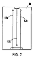
好ましくは、バルブ60は、電流が加えられるときにはセル20が使用中であることを示す開放状態にあり、電流が加えられていないときには閉鎖され、セル20が使用中でないことを示す。図3、図4、図6、図7、図8、図12、図32、図33A〜図33D、図34、図36〜図44、図53及び図54に関して説明される実施形態において、SMAワイヤ82a〜82eは、第2のバルブプレート66を引くが、押すことはない。従って、図3及び図4において、第1のSMAワイヤ82aは、バルブを引いて開放し、第2のSMAワイヤ82bは、バルブを引いて閉鎖する。図6に示す実施形態においては、2つのワイヤ82a及び82bは、バルブプレート66を1方向に引くのに利用され、2つの追加のワイヤ82c及び82dは、該プレートを反対方向に引くのに利用される。図7では、2つのワイヤ82a及び82bは、プレート66を1方向に引くのに使用され、単一のワイヤ82cは、該プレート66を反対方向に引くのに使用される。図8では、3つのワイヤ82a、82b及び82cは、このプレートを1方向に引くのに使用され、2つのワイヤ82d及び82eは、該プレートを反対方向に引くのに使用される。SMAワイヤ82は、平行に配置され、更にバルブプレート66の中心点の周りに対称的に設けられ、プレート66がシャーシ70内で拘束されるのを防ぐために均一な力が供給されるようにすることができる。一般に、SMAワイヤに加えられる電流がセルから供給される場合、アクチュエータの運動を開始させるためだけに電流が加えられ、セル容量の不必要な使用を防ぐためにアクチュエータが静止状態にある間は加えられないのが有利とすることができる。図示のように、SMAワイヤは、実質的に互いに平行に延びるように取り付けることができる。SMAワイヤはまた、プレート66が移動する方向(例えば、図3を参照)に平行に、又はプレート66が移動する方向(例えば、図9、図9A及び図9Bを参照)に垂直に延びるように取り付けることができる。
Preferably,
SMAワイヤは、従来のどのような形状記憶合金で作ってもよい。形状記憶合金は、ある温度では変形することができるが、加熱又は冷却されると以前の形状に戻る合金である。この性質は、マルテンサイト相とオーステナイト相との間の固相変態に起因する。好ましい形状記憶合金は、2方向形状記憶を有し、すなわち、変態が加熱時及び冷却時の両方において可逆的である。形状記憶合金の実施例には、ニッケル−チタン合金、ニッケル−チタン−銅合金、銅−亜鉛−アルミニウム合金、及び銅−アルミニウム−ニッケル合金が含まれ、ニッケル−チタン及びニッケル−チタン−銅が好ましい。ニッケル−チタン−銅(例えば、約5〜10重量パーセントの銅を有する)の使用は、耐疲労性の理由から何度も動作する可能性があるアクチュエータには有利とすることができる。ニッケル−チタン及び他の形状記憶合金の製造者には、Specialty Metals,Shaped Memory Alloy Division(米国ニューヨーク州New Hartford)、Memry Corporation(米国コネチカット州Bethel)及びDynalloy,Inc(米国カリフォルニア州Mesa)が含まれる。 The SMA wire may be made of any conventional shape memory alloy. Shape memory alloys are alloys that can deform at a certain temperature but return to their previous shape when heated or cooled. This property is due to the solid phase transformation between the martensite phase and the austenite phase. Preferred shape memory alloys have a two-way shape memory, ie the transformation is reversible both on heating and on cooling. Examples of shape memory alloys include nickel-titanium alloys, nickel-titanium-copper alloys, copper-zinc-aluminum alloys, and copper-aluminum-nickel alloys, with nickel-titanium and nickel-titanium-copper being preferred. . The use of nickel-titanium-copper (e.g., having about 5-10 weight percent copper) can be advantageous for actuators that may operate many times for fatigue resistance reasons. Manufacturers of nickel-titanium and other shape memory alloys include Specialty Metals, Shaped Memory Alloy Division (New Hartford, New York, USA), Memory Corporation (Bethel, Connecticut, USA), and Dynalloy, Inc. (USA) It is.
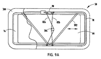
図9は、プレート66を移動させるためにSMAワイヤ82a及び82bに取り付ける別の手法を示している。この変形形態によれば、SMAワイヤ82a及び82bは、プレート66の最大寸法に沿って延びるように設けられておらず、代わりに、プレート66の運動方向に実質的に垂直である。第1のワイヤ82aは、加熱して収縮させることができ、第2のワイヤ82bは、加熱せずに屈曲可能になる。従って、プレート66は、第1の方向(実線で示すように図9で右側)に移動することができる。このプレートを反対方向(すなわち、左側)に移動させるためには、ワイヤ82aから電流を取り除き、従ってワイヤ82aが冷却して屈曲できるようにし、ワイヤ82bに電流を加えて、ワイヤ82bを加熱し収縮させるようにすることができる。これによって、プレート及びワイヤが図9の点線で示した位置まで移動するようになる。
FIG. 9 shows another approach for attaching the
シャーシ70は、制御回路90及びシャーシ本体72の上面に形成された回路トレースを有するものとして示されている。加えて、SMAワイヤ82a及び82bは、回路トレースと電気的に接触した状態でシャーシ70の上面に取り付けられる。シャーシ70は更に、図9では、該シャーシ70上に設けられた部品を封入して保護するために制御回路90及び回路トレースを覆って形成された外側被覆体300を有するものとして示している。従って、外側被覆体300は、シャーシ70の一部としての役割を果たす。外側被覆体300は、非導電性エポキシ又は他の外側被覆材料を含むことができる。加えて、外側被覆体300は更に、可動プレート66上で開口74を横断して延びる一体形成リブ302を含むものとして示されている。リブ302は、ほぼV字形に形成されて示され、下にある固定プレート62上で可動プレート66の中央部分を平坦に保持する役割を果たす。1つの実施形態においては、固定プレート62は、シャーシ70の底面側又はその外側被覆体300に接続され、電池セルは、シャーシ70の外側被覆体300の上面側に接続されている。
図9に示す実施形態においては、第1及び第2のSMAワイヤ82a及び82bは、可動プレート66に接続された別個のアクチュエータピン304a及び304bにそれぞれ係合する。図9Aに示す実施形態においては、単一のアクチュエータピン304は、流体調整システム50で利用することができる。単一のアクチュエータピン304を用いると、第1のSMAワイヤ82aは、ピン304の一方側に係合し、第2のSMAワイヤ82bは、ピン304の反対側に係合し、SMAワイヤ82a及び82bは、ピン304を反対方向に作動させ、プレート66を左右に移動させてバルブを開閉するようにする。この実施形態においては、アクチュエータピン304は、対応するSMAワイヤ82a及び82bに異なる高さで係合し、SMAワイヤ82a及び82bが互いに接触又は干渉しないようにするために、異なる高度に戻り止め又はスロットのようなワイヤ受け部を含むことができる。
In the embodiment shown in FIG. 9, the first and
図9Bを参照すると、別の実施形態による、流体調整システム50で使用される別のアクチュエータピン304が示されている。ピン304は第1及び第2の部分306a及び306bを含めて示されており、SMAワイヤ82aが部分306aを係合し、SMAワイヤ82bが部分306bに係合するようにほぼ矩形のピン304の残りの部分よりも高くなっている。部分306a及び306bは、図示のように直立部材を含むことができる。或いは、部分306a及び306bは、ピン又は他の構造体304内に形成されたスロットを含むことができる。従って、単一又は複数のアクチュエータ係合構造を利用して、SMAワイヤ82a及び82bがバルブを開閉するいずれかの方向に可動プレート66を作動させることが可能になるようにすることができる。
Referring to FIG. 9B, another
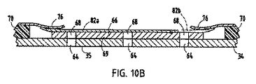
図10A及び図10Bは、缶34の外側表面に隣接して使用されるバルブ60の2つの図を示している。図10Aは、アパーチャ64及び68が整列しないようにケースバルブ60が閉鎖される休止中のセルを示している。図10Bは、セルが使用中であるときに生じるはずの開放位置に移動されたときのバルブの第2のプレート66位置を示している。これによって、アパーチャ64及び68が整列し、従って、流体がセル内部に流入するようになる。図示のように、SMAワイヤ82a及び82bは、該SMAワイヤを圧着、クランプ、はんだ付け、又は溶接することができる1対のバネコンタクト76によってシャーシ70に取り付けることができる。
10A and 10B show two views of the
図11は、本発明の様々な実施形態において利用することができるバルブ60の別の実施形態を示している。バルブ60は、複数のアパーチャ64を含む第1のプレート62を含む。プレート62は、シャーシ70に対して静止して保持された別個のプレートとすることができ、又は、セルハウジング30の缶又はカバーの一部分とすることができる。プレート62は、磁性物質又は非磁性物質とすることができる金属で作ることができる。バルブ60は更に、数、サイズ、形状及び位置がアパーチャ64及び第1のプレート62に対応する複数のアパーチャ68を含む第2のプレート66を含む。プレート66は、磁性物質又は非磁性物質とすることができる金属とすることができる。上述の実施形態と同様に、好ましくは非導電性材料で作られたシャーシ70は、プレート66を受けるための中央開口74を有する環状体72を含む。開口74は、プレート66がプレート62に対して直線的に摺動できるように1方向においてプレート66よりもわずかに大きくなるように構成され、アパーチャ64及び68が整列するよう及び整列しないように移動して、バルブ60を開放及び閉鎖することができるようにする。図11に示す実施は、レバーアーム84がアクチュエータ80の一部分として利用される限りにおいて、上記の実施例とは異なる。レバーアーム84は、該レバーアームがシャーシ70に旋回可能に固定できるようにシャーシ70内に形成されたアパーチャ又はスロット又は凹部78で受けられるピボットピン86を含む。例えば、これは、ピボットピン86の周りに適合し、且つピボットピン86とレバーアーム84の本体との間のネック部位内に部分的に延びてピボットピン86が凹部78内で捕捉されるが依然としてレバーアーム84が凹部78内で旋回できるように、凹部78を拡大し再形成することによって実施することができる。凹部78の底部にある棚部の穴で受けられるピボットピン86からの下向きの突起など、ピボットピン86をシャーシに固定する別の手段を利用してもよい。アクチュエータピン88は、好ましくは、レバーアーム84の本体から下方に延びて、当該ピンを第2のプレート66内に形成された穴67で受けることができるようにする。これにより、レバーアーム84がプレート66に係合し、従って第2のプレート66を第1のプレート62に対して摺動することが可能になる。この特定の構成において、1対のSMAワイヤ82a及び82bは、取り付け点89を介してレバーアーム84の上面に取り付けられる。ワイヤ82a及び82bの他の端部は、シャーシ70に取り付けることができる。ワイヤ82a及び82bは、例えば、凹部78と同様にシャーシ内の凹部に固定することができる。これらのワイヤは、接着剤又はピンで、或いは限定的なアパーチャを備えた凹部内に拡大ヘッドを嵌合させることによるなど、いずれかの好適な方法で固定することができる。SMAワイヤは、感知されたセル電圧に応答してSMAワイヤ82a及び82bに電流を選択的に加える制御回路(図11には示さず)に電気的に結合される。このようにして、SMAワイヤ82a及び82bは、レバーアームを2つの反対方向のいずれかに引くことができ、従って、レバーアーム84が第1のプレート62に対して第2のプレート66を摺動させるようにする。この場合、シャーシ70は、レバーアーム84及びSMAワイヤ82の端部の旋回点の取り付け場所としての役割を果たしながら、更にプレート62に対してプレート66を案内するガイドを提供する。
FIG. 11 illustrates another embodiment of a
SMAワイヤ及びレバーの別の構成を用いて、流体調整システムにおけるバルブを動作させることができる。例えば、SMAワイヤ82a及び82bは、単一の取り付け点89ではなく2つの別個の取り付け点を介してレバーアーム84に取り付けることができる。別の実施形態においては、SMAワイヤ82a及び82bは各々、図34に示すように、レバーアーム84の凹陥溝部85内にワイヤ82a及び82bを嵌合させることによって、各ワイヤの中心がレバー84に接続された状態で両端部においてシャーシ70に固定されている。
Other configurations of SMA wires and levers can be used to operate valves in the fluid regulation system. For example, the
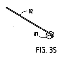
SMAワイヤは、いずれかの好適な方法で流体調整システムの構成部品に接続することができる。1つの実施形態において、SMAワイヤ82の一方の端部又は両端部は、図35に示すように好適なサイズにされたコネクタ87内に捕捉される。好ましくは、SMAワイヤ82はコネクタ87内に圧着される。任意選択的に、このワイヤは、圧着の前又は後で、コネクタに接着、溶接又ははんだ付けすることができる。次に、コネクタを構成部品(例えば、シャーシ70又はレバーアーム84)内の対応するアパーチャに挿入し、SMAワイヤ82をその構成部品に接続することができる。好ましくは、コネクタ85は、導電性であり、SMAワイヤ82とアパーチャを形成する構成部品の表面上に配置された制御回路の一部分との間で電気的に接触することができる。コネクタ87は、例えば、締まり嵌め、導電性接着、はんだ付け又は溶接によってアパーチャ内の所定場所に保持することができる。
The SMA wire can be connected to the components of the fluid conditioning system in any suitable manner. In one embodiment, one end or both ends of the
制御回路を用いて、開放又は閉鎖位置にバルブを移動させるのに必要な時間だけにSMAワイヤを通る電流の流れを制限する実施形態において、SMAワイヤは、電流が停止した後に元の長さに戻る(例えば、伸長する)ことができる。これが起こると、SMAワイヤは、プレートを所望の位置に保持することができなくなり、例えば、プレートが部分的な開放位置又は部分的な閉鎖位置まで摺動することが可能になる。これは、特に、摺動プレートを他方の位置に移動させるための相対するSMAワイヤが存在する場合に当てはまり、非作動の相対するSMAからの弾性張力は、作動したSMAが電流の停止に続いて伸長するときに摺動バルブを引くことができる。このような状況において、摺動プレートが意図的に所望の位置から移動されるまでは、当該プレートをその位置で保持することができる。摺動プレートを所望の位置で保持する手段の実施例はラッチ機構である。あらゆる好適な機構を使用することができる。1つの実施形態においては、バネ付勢された戻り止めを、摺動プレートの表面からの突起又は該表面内の凹部と協働させることができる。バネ力は、プレートが意図せずに摺動するのを防ぐのには十分であるが、プレートを他方の所望の位置に摺動させるための相対するSMAワイヤの動作によって容易に克服されるほど十分に弱くなるように選択することができる。 In embodiments in which the control circuit is used to limit the flow of current through the SMA wire only for the time required to move the valve to the open or closed position, the SMA wire is returned to its original length after the current has stopped. Can go back (eg, stretch). When this occurs, the SMA wire will not be able to hold the plate in the desired position, for example, allowing the plate to slide to a partially open or partially closed position. This is especially true when there is a counter SMA wire to move the sliding plate to the other position, where the elastic tension from the non-actuated counter SMA follows that the actuated SMA has stopped current. The sliding valve can be pulled when extended. In such a situation, the plate can be held at that position until the sliding plate is intentionally moved from the desired position. An example of means for holding the sliding plate in the desired position is a latch mechanism. Any suitable mechanism can be used. In one embodiment, a spring biased detent can cooperate with a protrusion from the surface of the sliding plate or a recess in the surface. The spring force is sufficient to prevent the plate from sliding unintentionally, but is easily overcome by the movement of the opposing SMA wire to slide the plate to the other desired position. You can choose to be weak enough.
別の実施形態においては、摺動プレートと別のセル又は流体調整システム構成部品との間の摩擦によって、摺動プレートが意図せずに摺動するのを防ぐ。プレートと他の構成部品との間の摩擦は、意図しない摺動を防ぐのには十分であるが、相対するSMAの動作により他方の位置への効率的な移動を妨げる程大きくはない。この摩擦は、摺動プレート及び他の構成部品用の材料の選択、一方又は両方の部品に施工されるコーティング、或いは隣接する表面の一方又は両方のテクスチャリングによって制御することができる。 In another embodiment, friction between the sliding plate and another cell or fluid conditioning system component prevents the sliding plate from sliding unintentionally. The friction between the plate and other components is sufficient to prevent unintentional sliding, but not so great as to prevent efficient movement to the other position by the movement of the opposing SMA. This friction can be controlled by the choice of material for the sliding plate and other components, the coating applied to one or both parts, or the texturing of one or both of the adjacent surfaces.
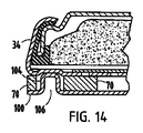
流体調整システム50は、以下に説明する様々な技術を使用してセル20の外部に固定することができる。図12に示すように、リッド100は、リッド100の内側表面から下方に延びて、シャーシ70上の対応する位置にある穴75を通る複数のスタンドオフ104を有するように構成することができ、スタンドオフ104を缶34の底部35に取り付けることができるようにする。図13及び図14は、図12で示した構成の2つの異なる構造を示している。
The
図13において、リッド100がプラスチックで形成されている構成が示されている。この場合、スタンドオフ104は、缶34の底部表面に超音波溶接することができる。この場合、リッド100と缶34との間に電気的接続は存在しないことになる。
FIG. 13 shows a configuration in which the
図14において、スタンドオフ104は、スタンピング又は同様のものなどによって形成することができる金属リッド100内の窪み/突起106として設けられる。この場合、金属リッド100は、缶34の底部表面35に抵抗溶接又はレーザ溶接することができる。
In FIG. 14, the
図15は、シャーシ70及びリッド100をセル20の外部に接続する別の方法を示している。この場合、バイア105は、リッド100を缶34に溶接するのに役立つシャーシ70の穴75を貫通して形成される。この溶接はまた、リッド100とセル20との間の電気的接続を行う。
FIG. 15 shows another method of connecting the
図16は、シャーシ70の穴75内に設けられた導電性エポキシ107を使用して金属リッド100が缶34に固定される更に別の技術を示している。更に別の代替形態として、流体調整システム50は、接着剤又は接着剤とラベル(図示せず)の組み合わせの使用により、缶34の底部表面に作られた1つ又はそれ以上の溝部内へのシャーシの圧入により、接着剤の利用に加えシャーシの圧入により、第2の最外部の缶がリッド100に置き換わることができる第2の缶内への缶34の圧着により、層構造のシャーシのはんだ付け又は溶接により、或いはエポキシ内への流体調整システム50の封入により、缶34の底部表面に固定することができる。
FIG. 16 illustrates yet another technique in which the
アクチュエータ80の好ましい構成部品としてのSMAワイヤの使用を上記で説明してきたが、人工筋肉に関連する直線状の電気活性高分子及びの曲線状の電気活性高分子などの他の構成部品又は材料を利用することもできる。このような材料は、より簡単な設計、電子機器が無いか又は簡単であること、及び電圧に対して比例的な応答であることを含む、潜在的利点を提供する。 Although the use of SMA wire as a preferred component of actuator 80 has been described above, other components or materials such as linear electroactive polymers and curved electroactive polymers associated with artificial muscles can be used. It can also be used. Such materials offer potential advantages, including a simpler design, no or simple electronics, and a proportional response to voltage.
別の考慮すべき点は、電池の初期起動に関する。電池は、開放位置のバルブと、従来のボタンエアセルに類似したタブにより保護される穴102とを備えて構築することができる。タブを取り外した後に空気が上昇することにより、セルが起動し、バルブの電子制御が開始され、更に電池の保管寿命が最大となる。或いは、電池は、機能する流体調整システムで構築することもできる。これにより、消費者は電池を直ちに使用できるようになるが、湿潤環境における湿気の進入及び乾燥環境における湿気の放出を防ぐために、好適なパッケージング及び倉庫、小売店の棚、その他における好適な保存条件が要求される場合がある。
Another consideration is related to the initial startup of the battery. The battery can be constructed with a valve in an open position and a
上述の構造において、缶34は、バルブ60の静止プレート62としての役割を果たすことが企図される。しかしながら、缶底部がその穴パターンを維持するように缶34を利用するのではなく、別個の固定プレート62を設けることが望ましいとすることができ、バルブ組立体の一体部分ではなくむしろ空気吹き出し機構に近い役割を果たすことができる。加えて、静止プレート62は、缶底部から離間して配置することができ、缶34が膨張、曲げ、又はしわが生じた場合に、バルブ60の動作を妨げないようにする。缶34は、より強い材料、より大きな厚み、又は異なる形状(例えば、底部の隆起部)で作ることができる点に留意されたい。別個の静止プレート62を利用することの更なる利点は、バルブ60は完全に予組み立てすることができ、従って、潤滑流体層69のより優れた安定性が提供されることである。しかしながら、これは、より厚い電池という代償で実現することができる。
In the structure described above, the
図面中の図には示していないが、セルハウジング30の外側表面にラベルを提供することができる。こうしたラベルは、導電体タブ110(以下で説明する)並びに流体調整システム50とセル20との間の接触面を更に覆い、また、缶34とカバー36との間の接触面を覆うように、セルの外周周りに延びることができる。電池の外側の電気接触端子を提供するために、カバー36及び缶34及び/又は導電性リッド100の十分な部分を露出したままにすることができる。
Although not shown in the drawings, a label can be provided on the outer surface of the
図1〜図3に示す特定のセル構造は、新規の角型セル設計である。この構造は、このセルの相対的なサイズ及び矩形性質の点で、従来のボタン型エアセルとは異なっている。この場合、従来のエアセル内で現在使用されている同様の空気電極、アノード、セパレータ及び缶/カバー材料は、セル20でも利用することができる。しかしながら、セル20は、図示のセルのような特定のサイズ、寸法又は相対寸法を有する必要はない点を当業者であれば理解されたい。
The particular cell structure shown in FIGS. 1-3 is a novel square cell design. This structure differs from conventional button type air cells in the relative size and rectangular nature of the cells. In this case, similar air electrodes, anodes, separators and can / cover materials currently used in conventional air cells can also be utilized in the
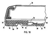
図17は、流体調整システム50がセルハウジング30の内部に配置されている本発明の別の実施形態を示している。図18は、この実施形態の一部の断面図を示している。これらの図に示すように、セルハウジングは、空気電極40と缶34の内側表面との間に流体調整システム50を収容するためにセルがわずかに厚くなっている場合がある点を除いては、上述の方法と同様にして構成されている。この実施形態において、シャーシ70はまた、セルの外部に適用される場合に上述したようなバルブ、アクチュエータ及び制御回路90と共に利用することができる。同様に、缶34の底部は、バルブ60の第1のプレート62としての役割を果たし、アパーチャ64としての役割を果たす複数の流体流入ポート32を含むことができる。この実施形態は、第2のプレート66が缶34の外部表面ではなく内側表面に沿って摺動する点で異なっている。以下に説明するこの実施形態及び他の実施形態では、シャーシ70及び従ってバルブ60は、ガスケット38によって適切な位置に保持することができる。
FIG. 17 illustrates another embodiment of the present invention in which the
内部流体調整システム50を利用する場合のセル20の構造における他の1つの相違点は、セルがその正及び負の接触端子の両方をアクチュエータの制御回路90に電気的に接続できるよう再構成する必要がある点である。この電気的接続を行う1つの方法が図17〜図19に示されている。図17に示すように、コンタクト開口39は、缶34の底部表面35内に形成されている。図18に示すように、負の接触端子94は、開口39を通って露出されるように、シャーシ内のバイアを通してシャーシ70の底部に設けられる。このようにして、導電体110は、接触端子94と電気的接触を形成しながら、セルハウジング30のカバー36に電気的に接続され、セル20の外側の周りに開口39まで延びることができる。これは、セルの負端子への接続を形成する。図18にも示したように、シャーシ70上に設けられた正の接触端子92は、セルの正端子への接続を形成するために缶34の内側表面に接触するように位置付けることができる。上述のように、接触端子92及び94は、制御回路90に電気的に接続し、検出されたセル電圧又は電流引き込みに応答してバルブを開閉するようにアクチュエータを制御することができる。
One other difference in the structure of the
図19に示すように、導電体110は、缶34とカバー36との間でのセルの短絡を防ぐ2つの絶縁層の間に配置される金属箔ストリップ112を含むタブとすることができる。第1の絶縁層114は、セルハウジング30と導電性金属箔112の間に配置することができる。この絶縁層114は、両面テープで作ることができる。第2の外側絶縁層116は、金属箔の上に配置され、片面テープのストリップを含むことができる。この特定の外部電気的接続は、内部流体調整システム50に関して図示されているが、カバー36と図1〜図3に示す外部流体調整システムの同様の接触端子94との間に電気経路を設けるため、同じ導電体110を適用することができる。この場合、コンタクト開口39に類似したアパーチャをリッド100内に形成することができ、或いは、導電体110は、単に、シャーシ70及び缶34間の接触面とシャーシ70及びリッド100間の接触面との間に延びることができる。
As shown in FIG. 19, the
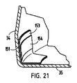
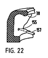
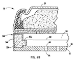
図20〜図23は、カバー36とシャーシ70上の端子94との間で電気的接続を行うことができる更に別の方法を示している。この実施形態において、缶34の内側表面の一部分は、図21に最もよく示されるように3層の材料でコーティングされている。第1の層は、電気絶縁層151であり、第2の層は、缶34との間に電気的接続がないように絶縁層151の上に施工される導電層153であり、第3の層は、空気電極40の縁部を導電層153から絶縁するために導電層153の一部の上に施工される電気絶縁層154である。図21に示すように、層151及び153は、缶34の内側底コーナーの周りに延び、シャーシ70の相対する表面上に形成された端子94に物理的に接触するように缶34の底部を十分に覆って延びる。上述のように、シャーシ70は、ガスケット38によって缶34の内側底部表面を押圧し、導電層153とコンタクト94との間の接触がこのような圧力によるものであるようにする。層151及び153は、缶34の接触面とガスケット38との間で缶34の側壁を上って延びる。図20、図22及び図23で最もよく示されるように、ガスケット38は、リベット又はピン157が貫通して延びることができるアパーチャ155を含むことができる。リベット又はピン157は、ガスケット38を通してカバー36と導電層153との間の電気的接続を形成し、これにより、カバー36とシャーシ70上のコンタクト94との間に導電路を完成する。リベット/ピン157は、ガスケット38内の適切な位置にモールド成形することができる。更に、1つよりも多いこのようなリベット/ピン157を使用してもよい。リベット/ピン157は、ガスケットの加圧を可能にするのに十分な長さを有することができる。層151、153及び154は、空気電極40の縁部が缶34の内側表面との電気的接触を形成できるようにするために、図21に示すようなストリップの形態である。
20-23 illustrate yet another way in which an electrical connection can be made between the
図24は、導電性ピン157が、ガスケット38のフランジ部分160内のアパーチャ155を通って垂直方向下向きに通る本発明の更に別の実施形態を示している。ピン157は、カバー36から、本実施形態においてはシャーシ70の上面上にある接触端子94(図24には示さず)への導電路を提供する。本実施形態は、ガスケット38のシール部分162を通るアパーチャを必要としない利点を提供する。更に、非導電性又は絶縁性の層が、缶34の内側表面に施工される必要もない。
FIG. 24 illustrates yet another embodiment of the present invention in which the
図25〜図28は、本発明の別の実施形態を示す。この実施形態によれば、異なる種類のバルブ170が、内部に取り付けられた流体調整システム内で使用される。バルブ170は、複数のアパーチャ174を有するバルブプレート172を含む。しかしながら、これらのアパーチャは、必ずしも缶34の底部の流体流入ポート32に対応するようなサイズ、形状、及び位置にする必要はない。これは、バルブプレート172が、缶34の底部表面35との相対的に平行な関係(バルブ閉鎖位置)と、図25に示すような曲げ/屈曲位置(バルブ開放位置)との間で移動することに起因する。この構造においては、プレート172のアパーチャ174は、プレート172が缶34の底部35に平行であるときに流体がセル内に流入することができないように、流体流入ポート32のいずれかと整列せず又は重なり合うことがない。プレート172が、閉鎖位置においてセルをシールするのに缶34の内側表面に十分に押圧されるようにするために、ガスケット38が缶34に対しプレート172の周囲縁部を押圧する。
Figures 25-28 illustrate another embodiment of the present invention. According to this embodiment, different types of
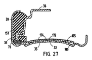
図26及び図27に示すように、別の構造では、ガスケット38の下の一方端のみで固定され、且つ缶底部34内に形成されたラッチ180を有するバルブプレート172を利用する。図26は、開放位置にあるバルブを示しており、図27は、閉鎖位置にあるバルブを示している。図28は、プレート172を開放位置に上昇及び/又は屈曲させるようプレート172に固定されたSMAアクチュエータ175を備えた、プレート172の斜視図を示している。開放位置におけるプレート172の移動は、空気電極(図示せず)によって制限することができる。
As shown in FIGS. 26 and 27, another construction utilizes a
上述のように、流体調整システムは、電子制御装置を使用して、セル(又は電池)電圧に一部基づいてバルブを動作させることができる。しかしながら、スイッチを使用して、バルブを開放又は閉鎖位置に移動させるために長さが変化するアクチュエータを介して電気回路を閉成することができ、次いで、バルブが完全な開放又は閉鎖位置に達したときに、回路を切断し、アクチュエータを介して電流の流れを止める。これにより、より複雑な制御回路の必要性が排除されると同時に、バルブの開放又は閉鎖を必要とするときにのみセルからエネルギを引き出すことが可能になる。スイッチは、電池自体に又は電池内に存在することができ、或いは、電池を使用する装置の一部分とすることができる。1つの実施形態において、装置オン/オフスイッチはまた、バルブを開閉するために相対するアクチュエータを介して回路を交互に閉成する。このような流体調整システムの操作が図33A〜図33Dに示されている。 As described above, the fluid regulation system can use an electronic controller to operate a valve based in part on the cell (or battery) voltage. However, a switch can be used to close the electrical circuit via an actuator that varies in length to move the valve to an open or closed position, and then the valve reaches a fully open or closed position. When this happens, the circuit is disconnected and the current flow is stopped via the actuator. This eliminates the need for more complex control circuitry while allowing energy to be extracted from the cell only when the valve needs to be opened or closed. The switch can be present in or within the battery, or can be part of a device that uses the battery. In one embodiment, the device on / off switch also alternately closes the circuit via opposing actuators to open and close the valve. The operation of such a fluid conditioning system is illustrated in FIGS. 33A-33D.
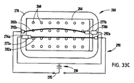
図33Aは、図3に示すバルブ60に類似したバルブ260の平面図を含む。バルブ260は、シャーシ270内に摺動可能に配置された可動プレート266を含む。可動プレート266は、図33Aでは閉鎖位置(すなわち、アパーチャ268が固定プレート内のアパーチャと整列していない状態)で示されている。SMAアクチュエータ282a及び282bは、可動プレート266とシャーシ270の相対する端部とに係止され、これらを用いてプレート266を引いてそれぞれ開放又は閉鎖させる。アクチュエータ282a及び282bは、平面電気コンタクト277a及び277bを介してプレート266にそれぞれ係止され、更に電気コンタクト292a及び292bをそれぞれ介してシャーシ270に係止されている。平面コンタクト277a及び277bがプレート266の上面の両端部の近くに配置され、よってこれらのコンタクトは、プレート266がそれぞれ開放位置又は閉鎖位置にあるときに、バネコンタクト276a及び276bと電気的に接触するようになる。バネコンタクト276a及び276bはまた、図式的に表された制御回路290の残りの部分に対する接続を形成するための接触端子としての役割を果たす。この制御回路は、オン/オフスイッチ295と、装置に電気エネルギを供給する流体減極型電池210とを含む。電池210が電気エネルギを必要としないときには、図33Aに示すように、スイッチ295はオフ位置にあり、バルブ260は閉鎖位置にある。アクチュエータ282a及び282bを含むどの回路も閉成されていないので、このアクチュエータを通って電流が流れず、従って、アクチュエータ282a及び282bは、周囲温度で且つ伸長状態にある。
FIG. 33A includes a plan view of a
スイッチ295が、オン位置に移動すると、電流がアクチュエータ282bに流れて、該アクチュエータが加熱し、短縮され、プレート266を左側の開放位置に引く。プレート266が、図33Bに示すように開放位置に到達すると、コンタクト276b及び277b間の電気的接続が切断される。回路が切断されると、アクチュエータ282bを通る電流が流れなくなる。これにより2つのことが達成される。第1に、電池210から更なるエネルギは引き込まれないが、装置はオンのままであり、第2に、アクチュエータ282bは、図33Cに示すように冷却されて伸長状態に戻り、従って、プレート266は左側に移動して戻ることができ、その時装置がオフになる。スイッチ295がオフ位置に移動すると、アクチュエータ282aを含む回路が閉成し、これを通る電流の流れがアクチュエータを短縮し、プレート266を右側の閉鎖位置に引く。プレート266が閉鎖位置に達すると、図33Dに示すように、コンタクト276a及び277a間の電気的接続が切断され、アクチュエータ282aを通る電流が流れなくなり、図33Aに示すようにアクチュエータを冷却して伸長させることができるようになる。
As
コンタクト276a、276b、277a及び277bへの電気的接続は、あらゆる好適な方法で実施することができる。例えば、シャーシ270を通して、或いはシャーシ270を覆うリッドとバルブ260のような、シャーシ270の上面と隣接する構成部品の対応する表面との間の接触面を通って、流体調整システムの縁部に対する接続を形成することができる。別の実施例において、電気的接続は、バルブ260を覆うリッドを貫通して延びる好適に配置されたコンタクトを通して形成することができる。セルの一部分であるスイッチは、リッドの外部表面上のようなセル及び/又は流体調整システムの好適な表面に取り付けることができる。或いは、スイッチは、複数のセル電池の外側表面上に、或いは電池が取り付けられる装置内に配置することができ、流体調整システムへの電気的接続は、対応するコンタクト間の溶接、はんだ付け又は圧力などによる好適な方法で形成される。別の実施形態においては、例えば、図6、図7及び図8に示す実施形態と類似の方法で、2つよりも多いアクチュエータを使用することができる。
Electrical connections to
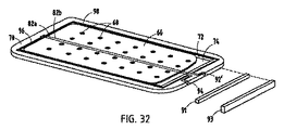
制御回路電子機器は、流体調整システム内に組み込むのではなく、外部に配置してもよい。これは、例えば電子機器を内部に好都合に収めることができない場合に望ましいとすることができる。1つの実施形態において、電子機器は、図32に示すように流体調整システム及び/又はセルの側壁上に取り付けられたキャップ内のような、流体調整システムの外側面上に取り付けることができる。図32は、図4のものに類似した、シャーシ70、可動プレート66、SMAワイヤ82a及び82b、並びに接触端子92’及び94を示している。但し図4とは異なり、図32のSMAワイヤ82a及び82bは、中間の制御回路90なしで接触端子92’及び94に直接接続されている。図32の制御回路は、回路基板91を保護するキャップ93と共にシャーシ70の側面に固定される回路基板91内に含まれている。シャーシ70上の接触端子92’及び94は、回路基板91の表面上の対応する端子と電気的に接触する。電気的接触は、圧力接触によるような、何らかの好適な方法で行うことができる。回路基板91は、単一の基板層を有することができ、2つ又はそれ以上の層を有する層状基板とすることができる。電子機器構成部品及び電気的接続は、プリント又は非プリント構成部品、或いはその組み合わせを含むことができる。より大きな構成部品を回路基板91の表面の凹部に配置し、シャーシ70及びキャップ93を同一平面に取り付けるようにすることができる。回路基板91とセルとの間の電気的接続は図示していないが、これらの接続はまたシャーシ70を通して形成することができる。
The control circuit electronics may be located externally rather than being incorporated within the fluid regulation system. This may be desirable, for example, when an electronic device cannot be conveniently housed inside. In one embodiment, the electronics can be mounted on the outer surface of the fluid conditioning system, such as in a cap mounted on the fluid conditioning system and / or cell sidewall as shown in FIG. FIG. 32 shows a
図36〜図43には更に、種々の付加的な実施形態による、SMAワイヤ82a及び82bを有するアクチュエータと可動プレート66を作動させるレバー84とを利用する流体調整システム50が示されている。図36及び図37に示すレバー84は、レバー84の一方端の近傍の枢動ピン86においてシャーシ70に旋回可能に接続されて図示され、レバー84は、SMAワイヤ82a及び82bに応答して枢動ピン86の周りを回転し、プレート66の移動にてこの作用を利用するようにする。レバー84の相対する端部の近くのアクチュエータピン88は、プレート66に係合する。
36-43 further illustrate a
レバー84の上面上に接続されるのは、一方端に設けられた摺動バネコンタクト312を有する導電体310である。SMAワイヤ82a及び82bは、取付け点89において導電体310に接続されている。摺動バネコンタクト312は、シャーシ70の上面上に設けられた電気回路トレース314と電気的に接触している。摺動バネコンタクト312は、下方に付勢されたバネであり、回路トレース314の上面に圧接し、枢動ピン86の周りをレバー84が回転するときに回路トレースとの間の十分な電気的接続を維持する。1つの実施形態において、回路トレース314は、電気接地に接続され、SMAワイヤ82a及び82bの一方に印加される電流は、導電体310から回路トレース314及び接地に導通される。
Connected on the upper surface of the
図38では、レバー84は、摺動バネコンタクトの代わりに導電体310と回路トレース314との間に接続された電気ワイヤ316を利用して示されている。ワイヤ316の一方端は、枢動ピン86において導電体310に接続され、他方端は、コネクタ318において回路トレース314に接続されて、接地への回路経路が完成する。本明細書では、電気接地に接続された回路トレース314を説明しているが、電流は回路トレース314に供給することができ、接地経路接続をSMAワイヤ82a及び82bの一方を介して形成して、電流を反対方向に導通させることができる点を理解されたい。
In FIG. 38,
図39〜図41を参照すると、本発明の別の実施形態による回転レバー84を利用する流体調整システム50が示されている。この実施形態において、レバー84は、可動プレート66内の細長いスロット320を貫通し下方に延びて静止プレート62内の開口322と係合する第1の中央伸長枢動ピン86’を利用している。開口322は、中央枢動ピン86’の回転を可能にし、ピン86’の横方向の移動を阻止する。レバー84は、可動プレート66内の開口67に係合する中央枢動ピン86’からある距離だけ変位した第2のピン88を有する。SMAワイヤ82a及び82bは、中央枢動ピン86’から変位した位置でレバー84に接続されて示されている。作動時には、SMAワイヤ82a及び82bは、中央枢動ピン86’を中心として時計回り又は反時計回りにレバー84を回転させるようなトルクを加える。
39-41, a
図40で分かるように、SMAワイヤ82aが通電された状態では、SMAワイヤ82aは加熱され、収縮してレバー84を引っ張り、レバー84を反時計方向に回転させて中央枢動ピン86’の周りに回転するようにし、可動プレート66を図示のように左側に摺動させる。図41で分かるように、SMAワイヤ82bを通電することによって、該SMAワイヤ82bが加熱され、収縮してレバー84を引き、中央枢動ピン86’の周りに時計方向に回転させ、可動プレート66が右側に摺動するようになる。レバー84が時計回り又は反時計回りに回転すると、可動プレート66は、アクチュエータピン88によって右側又は左側に摺動し、中央枢動ピン86’は、細長いスロット320が存在することで、プレート66の動きを妨げることがない。
As can be seen in FIG. 40, when the
図42〜図44には更に、弾性ヒンジ86”を有するシャーシ70の一部分として一体的に形成されたレバー84を利用する流体調整システム50が示されている。この実施形態においては、レバー84は、外側被覆体300を形成する前にシャーシ70の一部分として一体的に形成された同じ材料(例えば、エポキシ)で形成することができ、或いは、外側被覆体300の一部分として形成することができる。レバー84は、下方に延びて可動プレート66内の開口67と係合するアクチュエータピン88を有して形成される。SMAワイヤ82a及び82bはレバー84に接続される。レバー84は、可撓性ヒンジとして機能する狭幅部分86”を有し、レバー84がSMAワイヤ82a及び82bに応答して弾性ヒンジ86”の周りに屈曲し、アクチュエータピン88及びプレート66を図43に示すように左に、図44に示すように右に移動させてバルブを開放及び閉鎖するようにする。弾性ヒンジ86”は十分に薄く、SMAワイヤ82a及び82bが通電したときにレバー84の十分な移動を可能にする材料で作られる点を理解されたい。
42-44 further illustrate a
図45を参照すると、バルブの開閉を制御することによって電池への流体(例えば、空気)を調整する流体調整システム50が図示されており、該流体調整システムは、本発明の更なる実施形態による受動温度閉鎖部を更に含む。SMAワイヤ82aは、通電され、加熱されて収縮し、これによりアクチュエータピン304aを介して可動プレート66を開放バルブ位置(図45に示す)に移動させることができる。SMAワイヤ82bは、通電され、加熱されて収縮し、これによりアクチュエータピン304bを介して可動プレート66を閉鎖バルブ位置に移動させることができる。従って、バルブは、SMAワイヤ82a又は82bのいずれかに加えられた電流に応答して能動的に開閉することができる。加えて、SMAワイヤ82a及び82bは、本発明の1つの実施形態によるバルブの受動温度閉鎖部をもたらすように、異なる作動温度が選択される。SMAワイヤ82a及び82bは、不均衡な作動温度を有し、バルブの望ましい受動閉鎖が得られるようにする。このようにして、可動プレート66は、所定の温度限界を受けたときに閉鎖バルブ位置に移動される。
Referring to FIG. 45, there is illustrated a
図45に図示し説明する実施形態において、SMAワイヤ82aは、約90℃の第1の作動温度に設定され、SMAワイヤ82bは、より低温の約60℃の第2の温度に設定される。通電時には、SMAワイヤ82aは、加熱し収縮して力を加え、より高い第1の温度に達すると可動プレート66を開放位置に移動させる。同様に、SMAワイヤ82bは、通電されて加熱し収縮してバルブを作動させ、より低い第2の温度で可動プレート66を閉鎖位置に移動させることができる。第1の温度は、第2の温度よりも高く、SMAワイヤ82bの温度がより低い第2の温度に達したときにSMAワイヤ82bがバルブを閉鎖するようにする。従って、SMAワイヤ82a及び82bに加えられた電流に基づいてバルブを能動的に開閉することに加えて、周囲温度が最初により低い第2の温度に達したときに、SMAワイヤ82bが可動プレート66を閉鎖バルブ位置に押し出す点を理解されたい。環境温度がより高い第1の温度まで上昇し続けた場合、SMAワイヤ82aは、その閉鎖位置からバルブの位置を変化させる程十分な力を加えることはない。
In the embodiment illustrated and described in FIG. 45, the
SMAワイヤ82a及び82bは、市販のSMA構成部品を含むことができる。60℃作動SMAワイヤの1つの実施例は、Flexinolから市販されている0.102mm(0.004インチ)直径の60℃ワイヤである。90℃作動SMAワイヤの1つの実施例は、Flexinolから市販されている0.076mm(0.003インチ)直径の90℃ワイヤである。所与の実施例において、60℃SMAワイヤは、温度が低下して約40℃に戻るまで収縮したままであり、従って、温度ヒステリシスを生じる。
The
不均衡な温度SMAワイヤを利用する流体調整システム50は、有利には、所定温度を上回ると電池セルへの流体の流入を阻止するためにバルブを閉鎖する受動的方法を提供する。60℃のような所定温度で流体調整システム50を閉鎖することによって、電池の劣化を最小に又は回避することができる。加えて、60℃のような温度限界に達したときにバルブを移動させて閉鎖することにより、高温でのバルブの開放が阻止される。バルブを閉鎖する所定温度は45℃よりも高くすることができ、より具体的には、約60℃に設定することができる点を理解されたい。
The
1つの実施形態によれば、SMAワイヤ82a及び82bは、SMAワイヤ82bがSMAワイヤ82aによって生成される作動力よりも大きい作動力を生成するように、異なる作動力を生成するための異なる寸法を有して構成することができる。例示的な実施形態において、SMAワイヤ82bは、SMAワイヤ82aよりも大きな断面積(より大きい直径のような)を有する。より大きな断面積を有することで、SMAワイヤ82bは、周囲温度がより高い第1の温度に達した場合に、バルブの可動プレートにより大きな閉鎖力を加える。SMAワイヤ82a及び82bは、円形の断面とすることができ、第2のSMAワイヤは、より大きい直径を有する点を理解されたい。別の実施形態によれば、SMAワイヤ82a及び82bは、楕円形、正方形又は矩形などの別の断面形状を有することができ、第2のSMAワイヤ82bは、より大きい断面積をもたらすより大きな寸法を有し、結果として第1のSMAワイヤ82aよりも大きな作動力が得られることになる。別の実施形態においては、SMAワイヤ82a及び82bは、異なる断面積及び異なる相転移温度の両方を有することができ、周囲温度が上昇すると、一般的に最初にSMAワイヤ82bが作動し、周囲温度がSMAワイヤ82aのより高い相転移温度を上回って上昇したときでもバルブが閉鎖したままになる。
According to one embodiment, the
図46〜図50を参照すると、2つの実施形態による、電池セル20と、セル20及び外部環境間の圧力平衡化を可能にするシャーシ本体300を貫通した流体通路を有する流体調整システム50とを備えた流体消費電池10が示されている。図示の実施形態において、シャーシは、中央開口332及び内側に延びる棚部354を有する外側被覆体300によって全体的に示されている。エアセルのような流体消費電池セル20は、シャーシ300の上面に接続されている。流体流入ポート64を備えた固定プレート62は、シャーシ300の底部表面に接続され、ポート68を備えた可動プレート66は、内側に延びる棚部354の低い壁と固定プレート62との間に配置されてプレート62に対して移動できるようにされる。
46-50, a
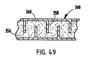
図46〜図49に示す実施形態において、外側被覆シャーシ本体300は、入口350とも呼ばれる第1のポートを有して全体的に示され、該ポートは、ほぼセル20と可動プレート66との間に配置され、開口332及びセル20と流体連通している。シャーシ本体300はまた、出口352とも呼ばれる第2のポートを有し、該ポートは外部環境につながる外側被覆材料の外側に設けられる。外側被覆シャーシ300は、非多孔性の外部層360と、流体通路356をもたらす多孔性の内部容積部とを有するように製造される。非多孔性の外部層360は、流体、特に空気に対してほぼ非透過性であり、1つの実施例によれば、エポキシを含むことができる。多孔性の内部容積部は、入口350から出口352まで延びる圧力平衡流体流通路356を提供する。多孔性の内部容積部は、細孔性のポリテトラフルオロエチレン材料又は多孔性不織布材料など、通路356を通って低拡散率で制限された空気流を可能にする空気透過性材料を含むことができる。代替的に又はこれに加えて、流体通路356は、低拡散率の空気流を可能にする十分に制限された通路を提供する空の空隙容積部を含むことができる。流体通路356は、有利には、空気を入口350から出口352に緩慢に通過させることができるが、該流体通路356は、入口350と出口352との間でいずれかの方向に流体が通過できるようにし、セル20と外部周囲環境との間の圧力平衡をもたらすこともできる。
46-49, the outer
流体通路356の入口350は、電池セル20とバルブプレート66及び62との間の開放容積部と流体連通している。電池セル20内のガスと外部環境との間に存在する圧力差により、ガスが流体通路を通って移動可能にすることができる。電池セル20がガスを発生すると、このガスは、制限された流体通路356を通って外部環境に移動し、バルブプレート66及び62間のシールが損なわれるのを防ぐことができる。これとは反対に、ガスが出口352から入口350に流れるのを許容することができるが、一般的には空気が電池セル20に供給できないように制限され、バルブが閉鎖されたときにセル20が高率で放電されないようにする。
The inlet 350 of the
1つの実施形態によれば、流体通路356は、湿気の増大又は減少に起因する室温での1年間当たりにセル容量の10%を超えない損失しかもたらさない空気拡散率を有する。流体通路356の多孔性の容積部は、蛇行した又は制限された空気流通路を提供するためにガスに対して全体的に多孔性の薄膜を含むことができるが、該薄膜は、流体のセル20への制限の無い自由な流れを許容するものではない点を理解されたい。1つの実施形態によれば、多孔性の容積部356は、図49に示すバッフル358によって提供されるような、蛇行性の流体通路356を含むことができる。バッフル358は、基本的に、外側被覆シャーシ300を通して空気流通路356の有効長を増大し、従って、正味有効流体流経路長が増大する。別の実施形態によれば、蛇行性の流体流経路は、全体的に多孔性のハニカムパターンを利用し、セル20に入る空気の量を最小にしながら、過剰なガスがセル20から外部環境に漏出可能にすることができる。
According to one embodiment, the
図50に示す実施形態において、外側被覆シャーシ本体300の上面には、全体的に曲がりくねった形状でスロット334が形成され、該スロットは、内側開口332の周りに矩形形状で該開口から約360°延びて、シャーシ300の外側表面につながっている。スロット334内には、該スロット334に収まるようなサイズに適合された全体構成を有する中空チューブ336が配置される。チューブ336は、シャーシ300の内側開口332及びセル20と流体連通して一方端に入口338とも呼ばれる第1のポートを有し、外部環境と流体連通して他端に出口340とも呼ばれる第2のポートを有する。シャーシ300の底部表面上に接続された固定プレート62が示されている。可動プレート66は、棚部354の下に配置され、固定プレート62にシール関係で隣接しており、プレート66がバルブを開閉するためにプレート62に対して移動可能であるようにする。
In the embodiment shown in FIG. 50, a
シャーシ300内に設けられたチューブ336は、入口338と出口340との間に延びる流体通路を提供し、電池セル20から放出された流体が、チューブ336の流体通路を通って外部環境に移動できるようになる。1つの実施形態によれば、流体入口338は、電池セル20と固定及び可動プレート62及び66との間の開口332の容積内の適切な位置に配置される。従って、チューブ336の延長された長さ及び小さな直径は、流体が十分に低い拡散率でセル20から漏出すると同時に、低い拡散率によりセル20への空気流入を十分に制限することが可能な蛇行性の流体通路を提供する。1つの実施形態において、チューブ336は、0.5mmよりも小さい十分に制限された内径と、少なくとも200mmの有効長とを有する。別の実施形態によれば、スロット334を覆って、チューブ336を使用する代わりの流体通路として利用することもできる。
A
図46〜図50の開示された実施形態において、電池セル20内のガスとセル20が曝される周囲外部環境との間に存在する圧力差により、その結果として流体障壁の故障につながる可能性がある破断が生じる可能性がある。従って、バルブプレート62及び66間の目的とする一次シール障壁が損なわれる可能性があり、場合によっては、水、酸素、水素及び二酸化炭素などの流体の制御されていない流入及び流出を許容することになり、結果として電池保管寿命の許容できない減少をもたらす可能性がある。シャーシ300内に設けられた圧力平衡流体通路336又は356は、ガスなどの流体が、流出及び流入用の流体通路を通って移動できるようにする。好適な長さの穴を適切なサイズで設けることによって、流体通路は、金属―エアセル内で発生した水素のようなガスの流出を可能にすると共に、セル20への酸素及び二酸化炭素の過剰な流入を阻止する。
In the disclosed embodiment of FIGS. 46-50, the pressure differential that exists between the gas in the
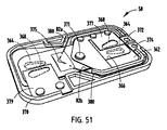
図51〜図54を参照すると、2つの実施形態による、静止プレート362に対して回転する可動プレート366を利用した流体調整システム50が全体的に図示されている。図49及び図50に示す実施形態において、流体調整システム50は、シャーシ370に組み付けられ且つ静止プレート362の上部上に整列される回転可能プレート366を利用する。静止プレート362は、1対の開口364を有し、可動プレート366は、互いに流体連通して整列し、電池セル(図示せず)への流体流入を制御する1対の開口368を有する。静止プレート362は、シャーシ370に固定されたままである。回転可能プレート366は、枢動ピン371の周りで、図51に示す閉鎖バルブ位置と図52に示す開放バルブ位置との間で回転する。閉鎖バルブ位置では、開口364及び368は、流体が電池セル内に流入するのを防ぐために整列しない。開放バルブ位置では、開口364及び368は、流体(例えば空気)が電池セルに入るのを可能にするために整列される。
Referring to FIGS. 51-54, a
図51及び図52の実施形態において示した流体調整システム50は、圧着部372及び374にてシャーシ370に接続されたSMAワイヤ82a及び82bを利用する。SMAワイヤ82a及び82bは更に、圧着部375にて回転可能プレート366に取り付けられる。SMAワイヤ82a及び82bは、1対の圧着部372、374と圧着部375との間でチャネル又はスロット380内に延びており、更にSMAワイヤ82a及び82bは、枢動ピン371からある距離で回転可能プレート366に接続されて、該プレート366が開放バルブ位置と閉鎖バルブ位置との間で回転できるようにする。実際には、SMAワイヤ82a及び82bに接続された回転可能プレート366は、枢動ピン371からある距離にてSMAワイヤ82a及び82bにより加えられる力をてこの作用で利用して回転可能プレート366を回転させる一体形成レバーを有する。加えて、バネ377及び379が回転可能プレート366の上部に設けられ、穴364及び368の近傍で回転可能プレート366を静止プレート362とシール関係で保持するための保持力を提供する。当業者には明らかなように、回転可能プレート366及び静止プレート362内に多少の流体流入穴を設けてもよい点は理解されたい。
The
図53及び図54を参照すると、更なる実施形態による回転可能プレートバルブ組立体を有する流体調整システム50が全体的に図示されている。この実施形態において、全体的にテーパ付きのスロット開口468を有する回転可能プレート466に接続されたレバー484が図示されている。回転可能プレート466の下には静止プレート462があり、開放バルブ位置において開口468と整列して電池セル(図示せず)への流体流入を可能にすることができる類似形状のテーパ付きスロット開口466を同様に含む。プレート462が固定された状態では、回転可能プレート466は、時計回り及び反時計回りに回転してバルブを閉鎖及び開放する。
Referring to FIGS. 53 and 54, a
レバー484は、シャーシ470のようなフレームプレート内に通常は配置される枢動ヒップ部486を有して示されている。枢動ヒップ部486は、形状がほぼ円形で、弾性アーム490によりフレームプレート470内に係合される。アーム490は、円形ヒップ部486を好適な位置に保持するのを助け、アクチュエータピン488の位置変動を低い程度にすることにより、開口464及び468の整列の変動を少なくすることができる。ヒップ部486により、レバー484は、SMAワイヤ82a及び82bによって提供される作動に応答して、図53に見られる一方のショルダ部492がプレート470に接触した状態の反時計回り位置から、図54に見られる他方のショルダ部494がプレート470に接触した状態の位置に回転できるようになる。ショルダ部492及び494は、移動ストップ部の端部として働き、他の実施形態では省略してもよい。SMAワイヤ82a及び82bは、1対の圧着部496及び498によりフレームプレート470に接続されて図示されており、これらのワイヤは更に、別の圧着部499を介してレバー484内に共に接続されている。圧着部499は電気接地経路を含むことができ、又は別の導電経路を通して接地経路を提供することができる。
作動時には、本実施形態の流体調整システム50は、SMAワイヤ82a及び82bの一方を通電し、レバー484を回転させてプレート466を開放バルブ位置と閉鎖バルブ位置との間で移動させることによって作動する。テーパ付きスロット464及び468により、ヒップ部486からの半径が増大したときのストロークの増大を経て、SMAワイヤ82a及び82bからの作動の連動がもたらされる点を理解されたい。
In operation, the
図51〜図54に示す回転バルブは、静止プレートに対する可動プレートの回転を可能にする。代替として、他の実施形態によれば、プレートの直線作動を行うことができ、或いは、静止プレートに対する可動プレートの直線運動と回転運動の組み合わせを行うことができる点を理解されたい。更には、バルブは、可動プレート及び静止プレートに接続されて説明してきたが、バルブが1つ又は2つの可動プレートを含み、一方のプレートが他のプレートに対して移動してバルブを開閉するようにできる点を理解されたい。 The rotary valve shown in FIGS. 51-54 allows rotation of the movable plate relative to the stationary plate. Alternatively, it should be understood that according to other embodiments, linear movement of the plate can be performed, or a combination of linear and rotational movement of the movable plate relative to the stationary plate can be achieved. Furthermore, although the valve has been described as connected to a movable plate and a stationary plate, the valve includes one or two movable plates so that one plate moves relative to the other plate to open and close the valve. I want you to understand what can be done.
以上、本発明を単一のセルを有する単一電池に関して説明してきたが、本発明の態様は、複数のセルを有する電池、及び複数の電池を有する電池パックにも適用することができる。例えば、流体調整システムは、電池パックのハウジング内に全体的に又は部分的に配置し、空気又は別の流体が電池パックハウジング内に移動可能にするバルブを選択的に開閉するようにすることができる。この場合、別個の流体調整システムは、各電池に対して必要とされることはない。更に、流体調整システムには、電池パック内の電池のいずれか1つ又はグループ、もしくは全てから、或いは電池パックの外部の別の電池から給電することができる。 As mentioned above, although this invention has been demonstrated regarding the single battery which has a single cell, the aspect of this invention is applicable also to the battery pack which has a some battery, and a battery which has a some cell. For example, the fluid conditioning system may be located in whole or in part in the battery pack housing to selectively open and close a valve that allows air or another fluid to move into the battery pack housing. it can. In this case, a separate fluid conditioning system is not required for each battery. Furthermore, the fluid conditioning system can be powered from any one or group, or all of the batteries in the battery pack, or from another battery external to the battery pack.
流体調整システムはまた、電池、複数の電池、又は電池パックによって給電され、或いは別に、電池、複数の電池又は電池パックとは別個に設けられた装置内に全体的に又は部分的に配置することができる。例えば、バルブは、様々な多セルパックサイズを提供する予めパッケージングされたモジュールとすることができる。従って、流体消費セルから別個にバルブ、バルブ電源及び制御部をパッケージングすることが有利な場合がある。 The fluid conditioning system may also be placed in whole or in part in a device powered by the battery, the plurality of batteries, or the battery pack, or separately from the battery, the plurality of batteries, or the battery pack. Can do. For example, the valve can be a prepackaged module that provides various multi-cell pack sizes. Thus, it may be advantageous to package the valve, valve power supply and controller separately from the fluid consuming cell.
流体消費電池と流体調整システムとの組み合わせは、1つ又はそれ以上の交換可能な流体消費電池が挿入される流体調整システムの全て又は一部を含むモジュールを含むことができる。これにより、流体調整システムの少なくとも一部分の再利用が可能になり、よって、ユーザに対する電池当たりのコストが削減される。このモジュールは、1つ又はそれ以上の流体入口を含むことができ、更に、内部通路、プレナム、或いは流体が電池に到達するための通路を提供する他の内部空間を含むことができる。このモジュール及び電池は、電池の一部分である対応する電気コンタクトと協働してモジュールと電池の意図しない分離を防ぐ目的のモジュールの一部分である電気コンタクトの使用を含む、いずれかの好適な方法で共に保持することができる。例えば、モジュール上の電気コンタクトは、電池電気コンタクトを含む電池ケース内のスロットにスナップ嵌合する突出ブレードの形態とすることができる。このブレードは、締まり嵌め、1つ又はそれ以上のバネ、機械的ロック機構及びその様々な組み合わせによるなどの、いずれかの好適な手段によってスロット内に保持することができる。モジュールと電池の寸法、形状及び電気コンタクトは、適切な電気的接触を保証し、電池の反転を防ぐために適切な方向にだけモジュールと電池が嵌合できるように構成することができる。モジュール、電池又はその両方は、組み合わされた電池とモジュールが取り付けられる装置と適切に電気的に接触するための外部接触端子を有することができる。幾つかの実施形態において、電池は、装置からモジュールを取り外すことなく交換することができる。 The combination of a fluid consuming battery and a fluid conditioning system can include a module that includes all or part of the fluid conditioning system into which one or more replaceable fluid consuming batteries are inserted. This allows reuse of at least a portion of the fluid conditioning system, thus reducing the cost per battery for the user. The module may include one or more fluid inlets, and may further include an internal passage, plenum, or other internal space that provides a passage for fluid to reach the battery. The module and battery are in any suitable manner, including the use of electrical contacts that are part of the module for the purpose of preventing unintentional separation of the module and battery in cooperation with corresponding electrical contacts that are part of the battery. Can be held together. For example, the electrical contacts on the module can be in the form of protruding blades that snap fit into slots in the battery case containing the battery electrical contacts. The blade can be retained in the slot by any suitable means, such as by an interference fit, one or more springs, a mechanical locking mechanism, and various combinations thereof. The module, battery dimensions, shape, and electrical contacts can be configured so that the module and battery can only mate in the proper orientation to ensure proper electrical contact and prevent battery reversal. The module, battery, or both can have external contact terminals for proper electrical contact with the combined battery and the device to which the module is attached. In some embodiments, the battery can be replaced without removing the module from the device.
本発明をその幾つかの好ましい実施形態に従って本明細書で詳細に説明してきたが、本発明の技術的思想から逸脱することなく、当業者が多くの修正及び変更を行うことができる。従って、本明細書で示した実施形態を説明する詳細事項及び手段によってではなく、添付の請求項の技術的範囲のみによって限定されるものとする。 Although the present invention has been described in detail herein according to certain preferred embodiments thereof, many modifications and changes can be made by those skilled in the art without departing from the spirit of the invention. Accordingly, it is not intended to be limited by the details and instrumentalities describing the embodiments shown herein, but only by the technical scope of the appended claims.
10 流体消費電池
20 流体消費セル
50 流体調整システム
62 固定プレート
64 流体流入ポート
66 可動プレート
68 流体流入ポート
82a 形状記憶合金アクチュエータ
82b 形状記憶合金アクチュエータ
DESCRIPTION OF
Claims (17)
前記セルハウジング内に配置された第2の電極と、
前記第1の流体消費電極に達するように前記少なくとも1つの流体流入ポートに流体を選択的に流入させることができるよう配置された流体調整システムと、
を備え、
前記流体調整システムが、
前記セルハウジングの外側表面に隣接して配置され、前記少なくとも1つの流体流入ポートと整列するように及び整列しないように移動するような少なくとも1つのプレートアパーチャを有する可動プレートと、
加熱されたときに前記可動プレートを移動させるための形状記憶合金構成部品を有するアクチュエータと、
前記可動プレートを覆い、前記可動プレートへの流体通路を提供する導電性リッドと、
を含み、
前記導電性リッドがセルの接触端子を提供する、
ことを特徴とする電池。 A cell housing having at least one fluid inflow port for passing a fluid therein; a first fluid consumption electrode disposed in the cell housing;
A second electrode disposed within the cell housing;
A fluid conditioning system arranged to selectively allow fluid to flow into the at least one fluid inlet port to reach the first fluid consuming electrode;
With
The fluid conditioning system comprises:
A movable plate disposed adjacent to an outer surface of the cell housing and having at least one plate aperture that moves in alignment with and out of alignment with the at least one fluid inlet port;
An actuator having a shape memory alloy component for moving the movable plate when heated;
A conductive lid that covers the movable plate and provides a fluid path to the movable plate;
Only including,
The conductive lid provides a contact terminal for the cell;
A battery characterized by that.
請求項1に記載の電池。 The movable plate slides linearly relative to the cell housing;
The battery according to claim 1.
請求項1に記載の電池。 The lid further covers the actuator;
The battery according to claim 1.
請求項1に記載の電池。 When a current flows through the shape memory alloy component, the shape memory alloy component is heated;
The battery according to claim 1.
請求項1に記載の電池。 The movable plate is substantially flat;
The battery according to claim 1.
請求項1に記載の電池。 The fluid conditioning system is at least partially provided in a module such that the first and second electrodes form a cell so that the module can replace the cell with another cell. Is removable from the cell housing;
The battery according to claim 1.
請求項6に記載の電池。 The module includes a fluid inlet and a passage between the module and the cell housing to allow fluid to reach the cell when the cell and the module are assembled together;
The battery according to claim 6.
請求項6に記載の電池。 After assembling together, the module and the cell cooperate to prevent unintentional separation of the module and the cell;
The battery according to claim 6.
請求項6に記載の電池。 The module includes an electrical contact terminal capable of supplying electrical energy from the cell to the electronic device.
The battery according to claim 6.
前記セルハウジング内に配置された第1の流体消費電極と、
前記セルハウジング内に配置された第2の電極と、
前記第1の流体消費電極に達するように前記少なくとも1つの流体流入ポートに流体を選択的に流入させることができるよう配置された流体調整システムと、
を備え、
前記流体調整システムが、
前記セルハウジングの外側表面に隣接して配置され、前記少なくとも1つの流体流入ポートと整列するように及び整列しないように移動するような少なくとも1つのプレートアパーチャを有する可動プレートと、
前記可動プレートを移動させるためのアクチュエータと、
前記可動プレートを覆い、前記可動プレートへの流体通路を提供する導電性リッドと、
を含み、
前記導電性リッドがセルの接触端子を提供する、
ことを特徴とする電池。 A cell housing having at least one fluid inflow port penetrating the side to allow fluid to pass through;
A first fluid consuming electrode disposed within the cell housing;
A second electrode disposed within the cell housing;
A fluid conditioning system arranged to selectively allow fluid to flow into the at least one fluid inlet port to reach the first fluid consuming electrode;
With
The fluid conditioning system comprises:
A movable plate disposed adjacent to an outer surface of the cell housing and having at least one plate aperture that moves in alignment with and out of alignment with the at least one fluid inlet port;
An actuator for moving the movable plate;
A conductive lid that covers the movable plate and provides a fluid path to the movable plate;
Only including,
The conductive lid provides a contact terminal for the cell;
A battery characterized by that.
請求項10に記載の電池。 The lid further covers the actuator;
The battery according to claim 10.
請求項10に記載の電池。 A chassis having an aperture for slidably receiving the movable plate;
The battery according to claim 10.
請求項12に記載の電池。 The actuator is disposed within the chassis;
The battery according to claim 12.
請求項12に記載の電池。 The chassis includes at least one hole, and the lid includes at least one standoff extending through the hole and attaching to the cell housing;
The battery according to claim 12.
請求項12に記載の電池。 The chassis includes at least one hole filled with a material that attaches to the lid and the cell housing;
The battery according to claim 12.
請求項12に記載の電池。 The chassis includes a printed circuit board;
The battery according to claim 12.
請求項10に記載の電池。 The lid is electrically coupled to the cell housing;
The battery according to claim 10.
Applications Claiming Priority (7)
| Application Number | Priority Date | Filing Date | Title |
|---|---|---|---|
| US79087606P | 2006-04-11 | 2006-04-11 | |
| US60/790,876 | 2006-04-11 | ||
| US81719906P | 2006-06-28 | 2006-06-28 | |
| US60/817,199 | 2006-06-28 | ||
| US86017506P | 2006-11-20 | 2006-11-20 | |
| US60/860,175 | 2006-11-20 | ||
| PCT/US2007/066415 WO2007121232A2 (en) | 2006-04-11 | 2007-04-11 | Battery including a fluid manager mounted external to cell |
Publications (2)
| Publication Number | Publication Date |
|---|---|
| JP2009533824A JP2009533824A (en) | 2009-09-17 |
| JP5366145B2 true JP5366145B2 (en) | 2013-12-11 |
Family
ID=38421495
Family Applications (6)
| Application Number | Title | Priority Date | Filing Date |
|---|---|---|---|
| JP2009505597A Active JP5219995B2 (en) | 2006-04-11 | 2007-04-11 | Battery including fluid management mechanism mounted inside cell |
| JP2009505605A Pending JP2009533828A (en) | 2006-04-11 | 2007-04-11 | Fluid management mechanism using two shape memory alloys and battery including the same |
| JP2009505601A Pending JP2009533827A (en) | 2006-04-11 | 2007-04-11 | Fluid management mechanism including lever and battery including the same |
| JP2009505594A Expired - Fee Related JP5290149B2 (en) | 2006-04-11 | 2007-04-11 | Fluid management mechanism having actuator mounted on chassis and battery including the same |
| JP2009505592A Expired - Fee Related JP5366145B2 (en) | 2006-04-11 | 2007-04-11 | Battery including fluid management mechanism mounted outside the cell |
| JP2009505589A Active JP5226662B2 (en) | 2006-04-11 | 2007-04-11 | Batteries including fluid management mechanisms |
Family Applications Before (4)
| Application Number | Title | Priority Date | Filing Date |
|---|---|---|---|
| JP2009505597A Active JP5219995B2 (en) | 2006-04-11 | 2007-04-11 | Battery including fluid management mechanism mounted inside cell |
| JP2009505605A Pending JP2009533828A (en) | 2006-04-11 | 2007-04-11 | Fluid management mechanism using two shape memory alloys and battery including the same |
| JP2009505601A Pending JP2009533827A (en) | 2006-04-11 | 2007-04-11 | Fluid management mechanism including lever and battery including the same |
| JP2009505594A Expired - Fee Related JP5290149B2 (en) | 2006-04-11 | 2007-04-11 | Fluid management mechanism having actuator mounted on chassis and battery including the same |
Family Applications After (1)
| Application Number | Title | Priority Date | Filing Date |
|---|---|---|---|
| JP2009505589A Active JP5226662B2 (en) | 2006-04-11 | 2007-04-11 | Batteries including fluid management mechanisms |
Country Status (6)
| Country | Link |
|---|---|
| US (7) | US7972718B2 (en) |
| EP (8) | EP2008338A2 (en) |
| JP (6) | JP5219995B2 (en) |
| KR (5) | KR101317076B1 (en) |
| IL (6) | IL194349A (en) |
| WO (7) | WO2007121254A1 (en) |
Families Citing this family (35)
| Publication number | Priority date | Publication date | Assignee | Title |
|---|---|---|---|---|
| KR101317076B1 (en) * | 2006-04-11 | 2013-10-11 | 더 테크놀로지 파트너십 피 엘 씨 | Fluid manager having a chassis-mounted actuator and a battery including the same |
| US7732089B2 (en) * | 2007-04-11 | 2010-06-08 | Eveready Battery Company, Inc. | Battery having fluid regulator with rotating valve |
| US7632585B2 (en) * | 2007-04-11 | 2009-12-15 | Eveready Battery Co., Inc. | Battery having fluid regulator with pressure equalization |
| US7833649B2 (en) * | 2007-04-11 | 2010-11-16 | Eveready Battery Company, Inc. | Battery fluid manager using shape memory alloy components with different actuation temperatures |
| US20080254341A1 (en) * | 2007-04-12 | 2008-10-16 | Bailey John C | Battery including a fluid manager |
| KR100824529B1 (en) * | 2007-05-03 | 2008-04-22 | 삼성에스디아이 주식회사 | Cathode end plate and air breathing fuel cell stack using the same |
| US8329357B2 (en) * | 2007-09-24 | 2012-12-11 | Eveready Battery Company, Inc. | Battery having fluid manager and sliding valve with friction reduction members |
| US7816027B2 (en) * | 2008-05-20 | 2010-10-19 | Eveready Battery Company, Inc. | System and method of controlling fluid to a fluid consuming battery |
| US8652665B2 (en) * | 2008-05-20 | 2014-02-18 | Eveready Battery Co. Inc. | System and method of controlling fluid to a fluid consuming battery |
| JP5130549B2 (en) * | 2008-05-30 | 2013-01-30 | Necディスプレイソリューションズ株式会社 | Filter, cooling injection member, and cooling air injection method |
| WO2010027422A2 (en) * | 2008-08-25 | 2010-03-11 | Eveready Battery Company, Inc. | Battery power supply having a fluid consuming battery with an improved fluid manager |
| US9353734B2 (en) * | 2008-10-13 | 2016-05-31 | GM Global Technology Operations LLC | Active material elements having reinforced structural connectors |
| US20100124688A1 (en) * | 2008-11-18 | 2010-05-20 | Eveready Battery Company, Inc. | Regulator Valve for a Fluid Consuming Battery |
| US20100124687A1 (en) * | 2008-11-18 | 2010-05-20 | Eveready Battery Company, Inc. | Fluid Manager Having Fluid Injection Primer for a Fluid Consuming Battery |
| TWI420726B (en) * | 2008-11-28 | 2013-12-21 | Fih Hong Kong Ltd | Battery cover assembly |
| TWI420727B (en) * | 2008-11-28 | 2013-12-21 | Fih Hong Kong Ltd | Battery cover latching structure |
| EP2361447B1 (en) * | 2008-12-22 | 2013-06-12 | Eveready Battery Company, Inc. | Device having fluid consuming battery and fluid manager |
| JP5353430B2 (en) * | 2009-05-14 | 2013-11-27 | トヨタ自動車株式会社 | Air battery system |
| JP5402277B2 (en) * | 2009-06-16 | 2014-01-29 | コニカミノルタ株式会社 | Actuator, drive device, and imaging device |
| CN102598399B (en) * | 2009-07-01 | 2014-10-15 | 永备电池有限公司 | Battery having an air manager with a moving plate valve |
| US8400292B2 (en) * | 2010-03-01 | 2013-03-19 | Andrew Llc | System and method for location of mobile devices in confined environments |
| US9374677B2 (en) | 2010-03-01 | 2016-06-21 | Commscope Technologies Llc | System and method for location of mobile devices in confined environments |
| WO2013055370A1 (en) * | 2011-10-14 | 2013-04-18 | Empire Technology Development Llc | Air exchanging thermally responsive wall panels and methods |
| KR20130097031A (en) * | 2012-02-23 | 2013-09-02 | 삼성에스디아이 주식회사 | Battery pack |
| DK3014394T3 (en) | 2013-07-05 | 2022-07-11 | Jacob A Rubin | WHOLE BODY HUMAN COMPUTER INTERFACE |
| KR102046879B1 (en) * | 2016-01-18 | 2019-11-20 | 주식회사 엘지화학 | Secondary battery |
| GB201603619D0 (en) * | 2016-03-02 | 2016-04-13 | Cambridge Mechatronics Ltd | SMA wire handling with air suction |
| KR101810085B1 (en) | 2017-02-07 | 2017-12-18 | 서울대학교산학협력단 | Controllable Pitch Propeller by Shape Memory Alloy |
| EP3732551A4 (en) | 2017-12-29 | 2021-12-08 | HAPTX Inc. | Haptic feedback glove |
| WO2019218072A1 (en) * | 2018-05-16 | 2019-11-21 | Smarter Alloys Inc. | Shape memory alloy valve and method for fabrication thereof |
| USD907445S1 (en) | 2018-12-11 | 2021-01-12 | Yeti Coolers, Llc | Container accessories |
| DE102020101291A1 (en) | 2020-01-21 | 2021-07-22 | Audi Aktiengesellschaft | Fuel cell plate |
| EP4232886A1 (en) | 2020-10-22 | 2023-08-30 | Haptx, Inc. | Actuator and retraction mechanism for force feedback exoskeleton |
| KR102352970B1 (en) * | 2021-06-07 | 2022-01-20 | 디스커버믹스테크매뉴팩처링 주식회사 | Electrolyte mixing parts of battery |
| US11592010B1 (en) | 2022-05-18 | 2023-02-28 | Toyota Motor Engineering & Manufacturing North America, Inc. | Shape-memory material actuators |
Family Cites Families (64)
| Publication number | Priority date | Publication date | Assignee | Title |
|---|---|---|---|---|
| JPS484826Y1 (en) * | 1969-01-23 | 1973-02-07 | ||
| US4296186A (en) * | 1975-08-22 | 1981-10-20 | Wolf Franz J | Two part pressure relief valve |
| US4177327A (en) | 1978-11-20 | 1979-12-04 | P. R. Mallory & Co. Inc. | Metal-air battery having electrically operated air access vent cover |
| US4262062A (en) * | 1980-03-24 | 1981-04-14 | Timex Corporation | Metal-air battery with environment control for intermittent high current demand |
| JPS61124778U (en) * | 1985-01-24 | 1986-08-06 | ||
| JPS6299531A (en) * | 1985-10-25 | 1987-05-09 | 松下電工株式会社 | Apparatus for removing cooling water and hot water |
| JPH0312074U (en) * | 1989-06-16 | 1991-02-07 | ||
| US5079106A (en) | 1990-02-09 | 1992-01-07 | Eveready Battery Company, Inc. | Air assisted alkaline cells |
| US5449569A (en) | 1992-05-20 | 1995-09-12 | Schumm, Jr.; Brooke | Fluid depolarized battery with improved automatic valve |
| US5837394A (en) * | 1992-05-20 | 1998-11-17 | Brooke Schumm, Jr. | Electric appliance and fluid depolarized cell with low parasitic usage microactuated valve |
| US5304431A (en) * | 1992-05-20 | 1994-04-19 | Schumm Jr Brooke | Fluid depolarized electrochemical battery with automatic valve |
| JP2591870Y2 (en) * | 1992-12-25 | 1999-03-10 | 東陶機器株式会社 | Thermostatic mixing valve |
| US5641588A (en) | 1994-09-01 | 1997-06-24 | Aer Energy Resources, Inc. | Portable battery with a retrofitting projection and wrist rest for use externally of an electronic device |
| US5554452A (en) * | 1994-09-22 | 1996-09-10 | Matsi, Inc. | Metal-air batteries having improved air access valves |
| US5733676A (en) | 1995-05-05 | 1998-03-31 | Rayovac Corporation | Metal-air cathode can and electrochemical cell made therewith |
| US5795667A (en) | 1995-05-05 | 1998-08-18 | Rayovac Corporation | Metal-air cathode can, and electrochemical cell made therewith |
| US6106962A (en) * | 1997-09-24 | 2000-08-22 | Aer Energy Resources Inc. | Air manager control using cell voltage as auto-reference |
| US6660418B1 (en) | 1998-06-15 | 2003-12-09 | Aer Energy Resources, Inc. | Electrical device with removable enclosure for electrochemical cell |
| ES2233072T3 (en) | 1998-08-27 | 2005-06-01 | Eidgenossische Technische Hochschule Zurich | PREPARATION OF GELS AND MULTIPLE LAYER SURFACE STRUCTURES WITH POLYMERS THAT INCLUDE BORIC ACID. |
| US6265094B1 (en) * | 1998-11-12 | 2001-07-24 | Aer Energy Resources, Inc. | Anode can for a metal-air cell |
| US6350537B1 (en) * | 1998-12-18 | 2002-02-26 | Aer Energy Resources, Inc. | Load responsive air door for an electrochemical cell |
| CA2355724A1 (en) * | 1998-12-18 | 2000-06-22 | Aer Energy Resources, Inc. | Diffusion controlled air vent with an interior fan |
| US6436564B1 (en) * | 1998-12-18 | 2002-08-20 | Aer Energy Resources, Inc. | Air mover for a battery utilizing a variable volume enclosure |
| US6383674B1 (en) | 1999-03-11 | 2002-05-07 | Eveready Battery Company, Inc. | Air-assisted electrochemical cell construction |
| US6962170B1 (en) * | 1999-07-30 | 2005-11-08 | The Procter & Gamble Company | Microvalve for controlling fluid flow |
| WO2001009520A1 (en) | 1999-07-30 | 2001-02-08 | The Board Of Trustees Of The University Of Illinois | Microvalve for controlling fluid flow |
| US6887615B1 (en) * | 1999-07-30 | 2005-05-03 | The Procter & Gamble Company | Microvalve for controlling fluid flow |
| US6492046B1 (en) * | 1999-08-13 | 2002-12-10 | The Gillette Company | Metal-air battery |
| US6641947B1 (en) | 1999-09-21 | 2003-11-04 | The Gillette Company | Air manager system for metal air battery |
| TW434927B (en) | 1999-11-03 | 2001-05-16 | Ind Tech Res Inst | Method for fabricating metal-air battery and its structure |
| US6558828B1 (en) | 2000-05-26 | 2003-05-06 | Eveready Battery Company, Inc. | Zn/air cell performance in extreme humidity by controlling hydrophobic layer porosity |
| WO2002031906A1 (en) * | 2000-10-12 | 2002-04-18 | Rayovac Corporation | Improved air manager for metal-air cells |
| US6384574B1 (en) * | 2000-10-20 | 2002-05-07 | The Gillette Company | Battery system |
| EP1334534A1 (en) | 2000-10-20 | 2003-08-13 | The Gillette Company | Battery |
| US7097928B1 (en) * | 2000-10-20 | 2006-08-29 | The Gillette Company | Battery and method of making a battery |
| US20020150814A1 (en) | 2001-02-01 | 2002-10-17 | Causton Brian Edward | Battery |
| US7056617B2 (en) * | 2001-02-01 | 2006-06-06 | The Gillette Company | Batteries and battery systems |
| CA2355535A1 (en) | 2001-08-22 | 2003-02-22 | Aluminum-Power, Inc. | Metal gas batteries |
| US6890674B2 (en) | 2002-02-19 | 2005-05-10 | Mti Microfuel Cells, Inc. | Methods and apparatuses for managing fluids in a fuel cell system |
| US6773842B2 (en) | 2002-03-26 | 2004-08-10 | Nanotek Instruments, Inc. | Metal-air battery with an extended service life |
| US20040048146A1 (en) | 2002-09-06 | 2004-03-11 | David Adamson | Electrochemical cells and systems |
| US7332238B2 (en) * | 2002-09-06 | 2008-02-19 | The Gillette Company | Electrochemical cells and systems |
| US20040175612A1 (en) * | 2003-03-07 | 2004-09-09 | Allen Conti | Electrochemical cell |
| CN2631052Y (en) * | 2003-06-13 | 2004-08-04 | 比亚迪股份有限公司 | Lithium ion cell |
| US20040265657A1 (en) | 2003-06-27 | 2004-12-30 | Gerhard Beckmann | Cathode fluid controlling assembly for use in a direct oxidation fuel cell system |
| US6955187B1 (en) * | 2003-07-16 | 2005-10-18 | Tini Alloy Company | Zinc-air battery control valve |
| US7740965B2 (en) * | 2003-08-01 | 2010-06-22 | The Gillette Company | Battery |
| US6844591B1 (en) * | 2003-09-17 | 2005-01-18 | Micron Technology, Inc. | Method of forming DRAM access transistors |
| US8088506B2 (en) * | 2003-11-26 | 2012-01-03 | Eveready Battery Company, Inc. | Fluid consuming battery with fluid regulating system |
| US20050136321A1 (en) * | 2003-11-26 | 2005-06-23 | Bailey John C. | Fluid consuming battery with fluid regulating system |
| WO2005069408A1 (en) | 2004-01-20 | 2005-07-28 | Matsushita Electric Industrial Co., Ltd. | Battery pack |
| CN100530768C (en) | 2004-10-29 | 2009-08-19 | 永备电池有限公司 | Fluid regulating microvalve assembly for fluid consuming cells |
| US20060134510A1 (en) * | 2004-12-21 | 2006-06-22 | Cleopatra Cabuz | Air cell air flow control system and method |
| US7618738B2 (en) | 2005-01-25 | 2009-11-17 | The Gillette Company | Air management system for zinc-air battery |
| US7625667B2 (en) * | 2005-03-14 | 2009-12-01 | Masco Corporation Of Indiana | Battery box assembly |
| US7611790B2 (en) | 2005-05-24 | 2009-11-03 | Robert Bosch Gmbh | Zinc/air battery with improved lifetime |
| JP2007032737A (en) * | 2005-07-28 | 2007-02-08 | Matsushita Electric Ind Co Ltd | Latch valve |
| KR101317076B1 (en) | 2006-04-11 | 2013-10-11 | 더 테크놀로지 파트너십 피 엘 씨 | Fluid manager having a chassis-mounted actuator and a battery including the same |
| US7618739B2 (en) | 2007-04-11 | 2009-11-17 | Eveready Battery Co., Inc. | Battery and fluid regulating system having chassis with molded electronics |
| US7632585B2 (en) | 2007-04-11 | 2009-12-15 | Eveready Battery Co., Inc. | Battery having fluid regulator with pressure equalization |
| US7833649B2 (en) | 2007-04-11 | 2010-11-16 | Eveready Battery Company, Inc. | Battery fluid manager using shape memory alloy components with different actuation temperatures |
| US7732089B2 (en) | 2007-04-11 | 2010-06-08 | Eveready Battery Company, Inc. | Battery having fluid regulator with rotating valve |
| US20080254341A1 (en) * | 2007-04-12 | 2008-10-16 | Bailey John C | Battery including a fluid manager |
| US8329357B2 (en) | 2007-09-24 | 2012-12-11 | Eveready Battery Company, Inc. | Battery having fluid manager and sliding valve with friction reduction members |
-
2007
- 2007-04-11 KR KR1020087026686A patent/KR101317076B1/en not_active IP Right Cessation
- 2007-04-11 EP EP07760468A patent/EP2008338A2/en not_active Withdrawn
- 2007-04-11 WO PCT/US2007/066449 patent/WO2007121254A1/en active Application Filing
- 2007-04-11 KR KR1020087026688A patent/KR101333413B1/en not_active IP Right Cessation
- 2007-04-11 EP EP07760460A patent/EP2008337A2/en not_active Withdrawn
- 2007-04-11 WO PCT/US2007/066437 patent/WO2007121244A2/en active Application Filing
- 2007-04-11 WO PCT/US2007/066415 patent/WO2007121232A2/en active Application Filing
- 2007-04-11 KR KR1020087026689A patent/KR101317116B1/en not_active IP Right Cessation
- 2007-04-11 US US11/734,014 patent/US7972718B2/en active Active
- 2007-04-11 US US11/734,031 patent/US7855006B2/en active Active
- 2007-04-11 EP EP07760507A patent/EP2005515A2/en not_active Withdrawn
- 2007-04-11 JP JP2009505597A patent/JP5219995B2/en active Active
- 2007-04-11 WO PCT/US2007/066459 patent/WO2007121261A2/en active Application Filing
- 2007-04-11 EP EP07760498A patent/EP2005514A1/en not_active Withdrawn
- 2007-04-11 EP EP07760488A patent/EP2005513A2/en not_active Withdrawn
- 2007-04-11 EP EP11188555A patent/EP2434574A1/en not_active Withdrawn
- 2007-04-11 JP JP2009505605A patent/JP2009533828A/en active Pending
- 2007-04-11 WO PCT/US2007/066404 patent/WO2007121226A2/en active Application Filing
- 2007-04-11 US US11/734,007 patent/US7732088B2/en active Active
- 2007-04-11 WO PCT/US2007/066464 patent/WO2007121266A2/en active Application Filing
- 2007-04-11 JP JP2009505601A patent/JP2009533827A/en active Pending
- 2007-04-11 US US11/733,990 patent/US7740976B2/en active Active
- 2007-04-11 JP JP2009505594A patent/JP5290149B2/en not_active Expired - Fee Related
- 2007-04-11 JP JP2009505592A patent/JP5366145B2/en not_active Expired - Fee Related
- 2007-04-11 KR KR1020087026690A patent/KR101317105B1/en not_active IP Right Cessation
- 2007-04-11 US US11/733,997 patent/US7833650B2/en active Active
- 2007-04-11 EP EP07760474A patent/EP2005512A2/en not_active Withdrawn
- 2007-04-11 EP EP07760512A patent/EP2033260A2/en not_active Withdrawn
- 2007-04-11 US US11/733,980 patent/US7858226B2/en active Active
- 2007-04-11 WO PCT/US2007/066423 patent/WO2007121235A2/en active Search and Examination
- 2007-04-11 US US11/734,043 patent/US7837744B2/en active Active
- 2007-04-11 JP JP2009505589A patent/JP5226662B2/en active Active
-
2008
- 2008-09-25 IL IL194349A patent/IL194349A/en not_active IP Right Cessation
- 2008-09-25 IL IL194348A patent/IL194348A/en not_active IP Right Cessation
- 2008-09-25 IL IL194347A patent/IL194347A/en not_active IP Right Cessation
- 2008-09-25 IL IL194350A patent/IL194350A/en not_active IP Right Cessation
- 2008-09-25 IL IL194336A patent/IL194336A/en not_active IP Right Cessation
- 2008-09-25 IL IL194335A patent/IL194335A0/en unknown
- 2008-10-30 KR KR1020087026685A patent/KR101268648B1/en not_active IP Right Cessation
Also Published As
Similar Documents
| Publication | Publication Date | Title |
|---|---|---|
| JP5366145B2 (en) | Battery including fluid management mechanism mounted outside the cell | |
| JP5529006B2 (en) | Battery fluid manager using shape memory alloy components at different operating temperatures | |
| JP5300836B2 (en) | Fluid regulation system having a chassis with a battery and molded electronics | |
| JP5521251B2 (en) | Battery with fluid regulator using pressure equalization | |
| EP2156509B1 (en) | A battery having fluid regulator with rotating valve | |
| JP5290150B2 (en) | Fluid management mechanism including electrical contacts and battery including the same |
Legal Events
| Date | Code | Title | Description |
|---|---|---|---|
| A621 | Written request for application examination |
Free format text: JAPANESE INTERMEDIATE CODE: A621 Effective date: 20100401 |
|
| A131 | Notification of reasons for refusal |
Free format text: JAPANESE INTERMEDIATE CODE: A131 Effective date: 20121022 |
|
| A601 | Written request for extension of time |
Free format text: JAPANESE INTERMEDIATE CODE: A601 Effective date: 20130121 |
|
| A602 | Written permission of extension of time |
Free format text: JAPANESE INTERMEDIATE CODE: A602 Effective date: 20130128 |
|
| A521 | Request for written amendment filed |
Free format text: JAPANESE INTERMEDIATE CODE: A523 Effective date: 20130222 |
|
| A131 | Notification of reasons for refusal |
Free format text: JAPANESE INTERMEDIATE CODE: A131 Effective date: 20130507 |
|
| A521 | Request for written amendment filed |
Free format text: JAPANESE INTERMEDIATE CODE: A523 Effective date: 20130726 |
|
| TRDD | Decision of grant or rejection written | ||
| A01 | Written decision to grant a patent or to grant a registration (utility model) |
Free format text: JAPANESE INTERMEDIATE CODE: A01 Effective date: 20130819 |
|
| A61 | First payment of annual fees (during grant procedure) |
Free format text: JAPANESE INTERMEDIATE CODE: A61 Effective date: 20130904 |
|
| R150 | Certificate of patent or registration of utility model |
Free format text: JAPANESE INTERMEDIATE CODE: R150 |
|
| S111 | Request for change of ownership or part of ownership |
Free format text: JAPANESE INTERMEDIATE CODE: R313115 |
|
| R250 | Receipt of annual fees |
Free format text: JAPANESE INTERMEDIATE CODE: R250 |
|
| R350 | Written notification of registration of transfer |
Free format text: JAPANESE INTERMEDIATE CODE: R350 |
|
| R250 | Receipt of annual fees |
Free format text: JAPANESE INTERMEDIATE CODE: R250 |
|
| LAPS | Cancellation because of no payment of annual fees |