JP5363648B2 - System and method for generating high frequency components of an audio signal - Google Patents
System and method for generating high frequency components of an audio signal Download PDFInfo
- Publication number
- JP5363648B2 JP5363648B2 JP2012512344A JP2012512344A JP5363648B2 JP 5363648 B2 JP5363648 B2 JP 5363648B2 JP 2012512344 A JP2012512344 A JP 2012512344A JP 2012512344 A JP2012512344 A JP 2012512344A JP 5363648 B2 JP5363648 B2 JP 5363648B2
- Authority
- JP
- Japan
- Prior art keywords
- signal
- subband
- analysis
- subband signals
- group
- Prior art date
- Legal status (The legal status is an assumption and is not a legal conclusion. Google has not performed a legal analysis and makes no representation as to the accuracy of the status listed.)
- Active
Links
Images


Classifications
-
- G—PHYSICS
- G10—MUSICAL INSTRUMENTS; ACOUSTICS
- G10L—SPEECH ANALYSIS OR SYNTHESIS; SPEECH RECOGNITION; SPEECH OR VOICE PROCESSING; SPEECH OR AUDIO CODING OR DECODING
- G10L19/00—Speech or audio signals analysis-synthesis techniques for redundancy reduction, e.g. in vocoders; Coding or decoding of speech or audio signals, using source filter models or psychoacoustic analysis
- G10L19/02—Speech or audio signals analysis-synthesis techniques for redundancy reduction, e.g. in vocoders; Coding or decoding of speech or audio signals, using source filter models or psychoacoustic analysis using spectral analysis, e.g. transform vocoders or subband vocoders
-
- G—PHYSICS
- G10—MUSICAL INSTRUMENTS; ACOUSTICS
- G10H—ELECTROPHONIC MUSICAL INSTRUMENTS; INSTRUMENTS IN WHICH THE TONES ARE GENERATED BY ELECTROMECHANICAL MEANS OR ELECTRONIC GENERATORS, OR IN WHICH THE TONES ARE SYNTHESISED FROM A DATA STORE
- G10H1/00—Details of electrophonic musical instruments
- G10H1/0091—Means for obtaining special acoustic effects
-
- G—PHYSICS
- G10—MUSICAL INSTRUMENTS; ACOUSTICS
- G10H—ELECTROPHONIC MUSICAL INSTRUMENTS; INSTRUMENTS IN WHICH THE TONES ARE GENERATED BY ELECTROMECHANICAL MEANS OR ELECTRONIC GENERATORS, OR IN WHICH THE TONES ARE SYNTHESISED FROM A DATA STORE
- G10H1/00—Details of electrophonic musical instruments
- G10H1/02—Means for controlling the tone frequencies, e.g. attack or decay; Means for producing special musical effects, e.g. vibratos or glissandos
- G10H1/06—Circuits for establishing the harmonic content of tones, or other arrangements for changing the tone colour
- G10H1/12—Circuits for establishing the harmonic content of tones, or other arrangements for changing the tone colour by filtering complex waveforms
- G10H1/125—Circuits for establishing the harmonic content of tones, or other arrangements for changing the tone colour by filtering complex waveforms using a digital filter
-
- G—PHYSICS
- G10—MUSICAL INSTRUMENTS; ACOUSTICS
- G10L—SPEECH ANALYSIS OR SYNTHESIS; SPEECH RECOGNITION; SPEECH OR VOICE PROCESSING; SPEECH OR AUDIO CODING OR DECODING
- G10L19/00—Speech or audio signals analysis-synthesis techniques for redundancy reduction, e.g. in vocoders; Coding or decoding of speech or audio signals, using source filter models or psychoacoustic analysis
- G10L19/04—Speech or audio signals analysis-synthesis techniques for redundancy reduction, e.g. in vocoders; Coding or decoding of speech or audio signals, using source filter models or psychoacoustic analysis using predictive techniques
- G10L19/26—Pre-filtering or post-filtering
- G10L19/265—Pre-filtering, e.g. high frequency emphasis prior to encoding
-
- G—PHYSICS
- G10—MUSICAL INSTRUMENTS; ACOUSTICS
- G10L—SPEECH ANALYSIS OR SYNTHESIS; SPEECH RECOGNITION; SPEECH OR VOICE PROCESSING; SPEECH OR AUDIO CODING OR DECODING
- G10L21/00—Processing of the speech or voice signal to produce another audible or non-audible signal, e.g. visual or tactile, in order to modify its quality or its intelligibility
- G10L21/02—Speech enhancement, e.g. noise reduction or echo cancellation
- G10L21/038—Speech enhancement, e.g. noise reduction or echo cancellation using band spreading techniques
-
- H—ELECTRICITY
- H03—ELECTRONIC CIRCUITRY
- H03M—CODING; DECODING; CODE CONVERSION IN GENERAL
- H03M7/00—Conversion of a code where information is represented by a given sequence or number of digits to a code where the same, similar or subset of information is represented by a different sequence or number of digits
- H03M7/30—Compression; Expansion; Suppression of unnecessary data, e.g. redundancy reduction
-
- G—PHYSICS
- G10—MUSICAL INSTRUMENTS; ACOUSTICS
- G10H—ELECTROPHONIC MUSICAL INSTRUMENTS; INSTRUMENTS IN WHICH THE TONES ARE GENERATED BY ELECTROMECHANICAL MEANS OR ELECTRONIC GENERATORS, OR IN WHICH THE TONES ARE SYNTHESISED FROM A DATA STORE
- G10H2210/00—Aspects or methods of musical processing having intrinsic musical character, i.e. involving musical theory or musical parameters or relying on musical knowledge, as applied in electrophonic musical tools or instruments
- G10H2210/155—Musical effects
- G10H2210/311—Distortion, i.e. desired non-linear audio processing to change the tone color, e.g. by adding harmonics or deliberately distorting the amplitude of an audio waveform
-
- G—PHYSICS
- G10—MUSICAL INSTRUMENTS; ACOUSTICS
- G10L—SPEECH ANALYSIS OR SYNTHESIS; SPEECH RECOGNITION; SPEECH OR VOICE PROCESSING; SPEECH OR AUDIO CODING OR DECODING
- G10L21/00—Processing of the speech or voice signal to produce another audible or non-audible signal, e.g. visual or tactile, in order to modify its quality or its intelligibility
- G10L21/02—Speech enhancement, e.g. noise reduction or echo cancellation
- G10L21/038—Speech enhancement, e.g. noise reduction or echo cancellation using band spreading techniques
- G10L21/0388—Details of processing therefor
Description
本発明は、高周波再構築(HFR)のためのハーモニックトランスポジションを利用するオーディオコーディングシステムや、高調波歪の生成が処理信号にブライトネス(brightness)を加える所謂エキサイタのようなディジタルエフェクトプロセッサに関連する。特に、本願は高周波再構築のための簡易な方法に関連する。 The present invention relates to an audio coding system that uses harmonic transposition for high frequency reconstruction (HFR), and a digital effects processor such as a so-called exciter where the generation of harmonic distortion adds brightness to the processed signal. . In particular, the present application relates to a simple method for high frequency reconstruction.
特許文献1(WO98/57436)において、オーディオ信号の低い周波数バンドから高い周波数バンドを作り直す方法として、トランスポジション(transposition)の概念が確立されている。オーディオコーディングにおいてこの概念を使用することで、ビットレートのかなりの削減効果が得られる。HFRを用いたオーディオコーディングシステムの場合、信号の低周波数成分として言及される低帯域幅信号がコア波形コーダに与えられ、デコーダ側における高周波成分の目標のスペクトル形状を記述する非常にビットレートが低い付加サイド情報及び信号トランスポジションを利用して、信号の高周波成分として言及される高周波が再生成される。低いビットレートの場合、コアの符号化信号の帯域幅(すなわち、低バンド信号又は低周波数成分)は狭いので、知覚的に心地よい特性の高バンド信号(すなわち、高周波成分)を再生成することはますます重要になる。特許文献1(WO98/57436)で規定されているハーモニックトランスポジションは、低いクロスオーバ周波数の状況において、すなわち低バンド信号の上限周波数が低い状況において、複雑な音楽内容について良好に機能する。ハーモニックトランスポジションの原理は、周波数ωの正弦波を周波数Tωの正弦波にマッピング又は対応付けることであり、ここでT>1はトランスポジションの次数(すなわち、トランスポジション次数)を指定する整数である。これに対して、単一の再度バンド変調(SSB)を用いたHFRは、周波数ωの正弦波を周波数ω+Δωの正弦波にマッピングし、ここでΔωは一定の周波数シフト量である。低い帯域幅のコア信号(すなわち、上限周波数が低い低バンド信号)の場合、SSBトランスポジションは、通常、耳障りな共鳴アーチファクト(dissonant ringing artifact)を招くので、この点はハーモニックトランスポジションと比較した場合の欠点である。 In Patent Document 1 (WO98 / 57436), the concept of transposition is established as a method of recreating a high frequency band from a low frequency band of an audio signal. By using this concept in audio coding, a significant reduction in bit rate can be achieved. For audio coding systems using HFR, a low bandwidth signal, referred to as the low frequency component of the signal, is provided to the core waveform coder, which describes the target spectral shape of the high frequency component at the decoder side and has a very low bit rate Using the additional side information and signal transposition, the high frequency referred to as the high frequency component of the signal is regenerated. At low bit rates, the bandwidth of the core encoded signal (i.e. low band signal or low frequency component) is narrow, so regenerating a high band signal (i.e. high frequency component) with a perceptually pleasing characteristic Becoming increasingly important. The harmonic transposition defined in Patent Document 1 (WO98 / 57436) functions well for complex music contents in a low crossover frequency situation, that is, in a situation where the upper limit frequency of a low-band signal is low. The principle of harmonic transposition is to map or associate a sine wave of frequency ω with a sine wave of frequency Tω, where T> 1 is an integer that specifies the order of the transposition (ie, the transposition order). On the other hand, an HFR using a single band modulation (SSB) again maps a sine wave of frequency ω to a sine wave of frequency ω + Δω, where Δω is a constant frequency shift amount. For low-bandwidth core signals (i.e., low-band signals with low upper frequency limits), SSB transposition usually leads to annoying resonance artifacts, so this is compared to harmonic transposition. Is a drawback.
改善されたオーディオ品質を達成し、かつ高バンド信号に必要な帯域幅を合成するために、ハーモニックHFR法は典型的にはいくつもの次数のトランスポジションを使用する。
様々なトランスポジション次数の複数のトランスポジションを実行するため、従来法は、分析ステージ、合成ステージ又はそれら双方において複数のフィルタバンクを必要とする。典型的には、異なるトランスポジション次数の各々について異なるフィルタバンクが必要である。コア波形コーダが最終的な出力信号のサンプリングレートよりも低いサンプリングレートで動作する場合、典型的には、コア信号を出力信号のサンプリングレートに変換する追加的な要請があり、そのようなコア信号のアップサンプリングは、通常、更に別のフィルタバンクを追加することで行われる。従って、異なるトランスポジション次数の種類の増加と共に、演算処理負担が著しく重くなってしまう。
In order to achieve improved audio quality and synthesize the bandwidth required for high-band signals, the harmonic HFR method typically uses a number of orders of transposition.
In order to perform multiple transpositions of various transposition orders, conventional methods require multiple filter banks in the analysis stage, the synthesis stage, or both. Typically, a different filter bank is required for each different transposition order. When a core waveform coder operates at a lower sampling rate than the final output signal sampling rate, there is typically an additional requirement to convert the core signal to the output signal sampling rate, such core signal. The upsampling is usually performed by adding another filter bank. Therefore, as the types of different transposition orders increase, the calculation processing burden becomes extremely heavy.
異なるトランスポジション次数の種類の増加と共に、演算処理負担が著しく重くなってしまう従来の問題を少なくとも軽減すること。 To at least alleviate the conventional problem of increasing the processing load with increasing number of different transposition orders.
一実施形態によるシステムは、
信号の低周波成分から該信号の高周波成分を生成するシステムであって、
前記信号の前記低周波成分から少なくとも2つの分析サブバンド信号を含む一群の分析サブバンド信号を提供する、Δfの周波数分解能を有する分析フィルタバンクと、
あるトランスポジション次数Pを用いて前記一群の分析サブバンド信号から一群の合成サブバンド信号を決定する非線形処理部であって、前記一群の合成サブバンド信号は、前記トランスポジション次数Pから導出された量だけ位相がシフトされた前記一群の分析サブバンド信号の一部分に基づいて決定する非線形処理部と、
前記一群の合成サブバンド信号からの信号の高周波成分を生成する、FΔfの周波数分解能を有する合成フィルタバンクであって、前記FはF≧1であって分解能因子であり、前記トランスポジション次数Pは前記分解能因子Fとは異なる、合成フィルタバンクと
を有するシステムである。
The system according to one embodiment comprises:
A system for generating a high frequency component of a signal from a low frequency component of the signal,
An analysis filter bank having a frequency resolution of Δf that provides a group of analysis subband signals including at least two analysis subband signals from the low frequency component of the signal;
A non-linear processing unit that determines a group of synthesized subband signals from the group of analysis subband signals using a certain transposition order P, wherein the group of synthesized subband signals is derived from the transposition order P A non-linear processing unit that determines based on a portion of the group of analysis subband signals that are phase shifted by an amount;
A synthesis filter bank having a frequency resolution of FΔf that generates high-frequency components of signals from the group of synthesis subband signals, wherein F is a resolution factor and F ≧ 1, and the transposition order P is And a synthesis filter bank different from the resolution factor F.
本発明は、分析フィルタバンク群及び合成フィルタバンク群のペアをいくつものハーモニックトランポーザで共用可能にすることにより、又は1つ以上のハーモニックトランスポーザ及びアップサンプラにより、ハーモニックHFR方法の複雑さを低減する方法を提供する。提案する周波数ドメインのトランスポジションは、分析フィルタバンクからの非線形に修正されたサブバンド信号を、合成フィルタバンクの選択されたサブバンドにマッピングすることを含む。サブバンド信号に関する非線形処理は何倍にも増やす位相乗算を含む。更に本発明はHFRシステムの複雑さを低減するいくつもの形態を提供する。 The present invention reduces the complexity of the harmonic HFR method by allowing a pair of analysis filter banks and synthesis filter banks to be shared by any number of harmonic transposers or by one or more harmonic transposers and upsamplers Provide a way to do it. The proposed frequency domain transposition involves mapping a non-linearly modified subband signal from the analysis filterbank to a selected subband of the synthesis filterbank. Non-linear processing on subband signals includes phase multiplication that increases many times. In addition, the present invention provides several forms that reduce the complexity of the HFR system.
一実施形態として、信号の低周波成分から該信号の高周波成分を生成するシステムが説明される。本システムは、信号の前記低周波成分から、少なくとも2つの分析サブバンド信号を典型的には含む一群の分析サブバンド信号を提供する分析フィルタバンクを有する。合成フィルタバンクはΔfの周波数分解能とLA個の分析フィルタバンクとを有し、LA>1であり、分析サブバンドのインデックスkは、k=0,...,LA-1である。特に、分析フィルタバンクは、大きさのサンプル及び位相のサンプルを有する一群の複素分析サブバンド信号を提供する。 In one embodiment, a system for generating a high frequency component of a signal from a low frequency component of the signal is described. The system includes an analysis filter bank that provides a group of analysis subband signals, typically including at least two analysis subband signals, from the low frequency component of the signal. The synthesis filter bank has a frequency resolution of Δf and L A analysis filter banks, L A > 1, and the analysis subband index k is k = 0, ..., L A-1 . In particular, the analysis filter bank provides a group of complex analysis subband signals having magnitude samples and phase samples.
本システムは、あるトランスポジション次数Pを用いて一群の分析サブバンド信号から一群の合成サブバンド信号を決定する非線形処理部を更に有し、一群の合成サブバンド信号は、トランスポジション次数Pから導出された量だけ位相がシフトされた一群の分析サブバンド信号の一部分を典型的には有する。言い換えれば、一群の合成サブバンド信号は、トランスポジション次数Pから導出された量だけ位相がシフトされた一群の分析サブバンド信号の一部分に基づいて決定される。分析サブバンド信号の位相シフトは、分析サブバンド信号の位相サンプルに、トランスポジション因子Pから導出された量を乗算することで行われてもよい。その場合、一群の合成サブバンド信号は一群の分析サブバンド信号の一部又は部分集合に対応し、サブバンドサンプルの位相にはトランスポジション次数から導出された量が乗算されている。特に、トランスポジション次数から導出された量は、トランスポジション次数の分数(fraction)であってもよい。 The system further includes a non-linear processing unit that determines a group of synthesized subband signals from a group of analysis subband signals using a certain transposition order P, and the group of synthesized subband signals is derived from the transposition order P. Typically have a portion of a group of analytic subband signals that are phase shifted by a given amount. In other words, the group of synthesized subband signals is determined based on a portion of the group of analyzed subband signals that are phase shifted by an amount derived from the transposition order P. The phase shift of the analysis subband signal may be performed by multiplying the phase sample of the analysis subband signal by an amount derived from the transposition factor P. In that case, the group of synthesized subband signals corresponds to a part or subset of the group of analysis subband signals, and the phase of the subband samples is multiplied by an amount derived from the transposition order. In particular, the amount derived from the transposition order may be a fraction of the transposition order.
本システムは、一群の合成サブバンド信号から信号の高周波成分を生成する、FΔfの周波数分解能を有する合成フィルタバンクを有する。FはF≧1であって分解能因子であり、合成フィルタバンクがLS個の合成サブバンドを有し、LS>1であり、合成サブバンドのインデックスnは、n=0,...,LS-1である。トランスポジション次数Pは分解能因子Fとは異なる。分析フィルタバンクは分析時間幅(分析時間ストライド)ΔtAを使用し、合成フィルタバンクは合成時間幅(合成時間ストライド)ΔtSを使用し、分析時間幅ΔtA及び合成時間幅ΔtSは等しくてもよい。 The system includes a synthesis filter bank having a frequency resolution of FΔf that generates a high frequency component of a signal from a group of synthesis subband signals. F is F ≧ 1 and is a resolution factor, the synthesis filter bank has L S synthesis subbands, L S > 1, and the synthesis subband index n is n = 0, ... , L S-1 . The transposition order P is different from the resolution factor F. The analysis filter bank uses the analysis time width (analysis time stride) Δt A , the synthesis filter bank uses the synthesis time width (synthesis time stride) Δt S , and the analysis time width Δt A and the synthesis time width Δt S are equal. Also good.
トランスポジション次数Pにより位相がシフトされた一群の分析サブバンド信号に属する分析サブバンド信号、又は一群の合成サブバンド信号中の一対の分析サブバンド信号に基づいて、非線形処理部は一群のサブバンド信号の合成サブバンド信号を決定し、一対のサブバンド信号の第1のメンバは因子P’によりシフトされた位相を有し、一対のサブバンド信号の第2のメンバは因子P”によりシフトされた位相を有し、P’+P”=Pである。上記の処理は合成及び分析サブバンド信号のサンプルについて実行されてもよい。言い換えれば、分析サブバンド信号のサンプルは、トランスポジション次数Pにより位相がシフトされた分析サブバンド信号のサンプルに基づいて、又は分析サブバンド信号の対応するペアからのサンプルペアに基づいて決定されてもよい。サンプルペアの内の第1のサンプルは因子P’だけ位相がシフトされており、サンプルペアの内の第2のサンプルは因子P”だけ位相がシフトされている。 Based on the analysis subband signal belonging to the group of analysis subband signals whose phase is shifted by the transposition order P, or the pair of analysis subband signals in the group of synthesis subband signals, the nonlinear processing unit performs the group of subbands. Determine the combined subband signal of the signal, the first member of the pair of subband signals has a phase shifted by a factor P ′, and the second member of the pair of subband signals is shifted by a factor P ″ P ′ + P ″ = P. The above processing may be performed on samples of synthesized and analyzed subband signals. In other words, the samples of the analysis subband signal are determined based on samples of the analysis subband signal that are phase shifted by the transposition order P, or based on sample pairs from the corresponding pair of analysis subband signals. Also good. The first sample in the sample pair is phase shifted by a factor P 'and the second sample in the sample pair is phase shifted by a factor P ".
非線形処理部は、一群の分析サブバンド信号の内のk番目の分析サブバンド信号及び隣接する(k+1)番目の分析サブバンド信号の組み合わせから、一群の合成サブバンド信号の内のn番目の合成サブバンド信号を決定する。特に、非線形処理部は、k番目の分析サブバンド信号の位相シフト及び(k+1)番目の分析サブバンド信号の位相シフトの総和としてn番目の合成サブバンド信号の位相を決定する。代替的又は付加的に、非線形処理部は、k番目の分析サブバンド信号の指数表示における大きさ及び(k+1)番目の分析サブバンド信号の指数表示における大きさの積としてn番目の合成サブバンド信号の大きさを決定する。 The non-linear processing unit is configured to calculate the nth of the group of synthesized subband signals from the combination of the kth analysis subband signal of the group of analysis subband signals and the adjacent (k + 1) th analysis subband signal. Determine the combined subband signal. In particular, the non-linear processing unit determines the phase of the nth synthesized subband signal as the sum of the phase shift of the kth analysis subband signal and the phase shift of the (k + 1) th analysis subband signal. Alternatively or additionally, the non-linear processing unit may combine the nth product as the product of the magnitude in the exponential representation of the kth analysis subband signal and the magnitude in the exponential representation of the (k + 1) th analysis subband signal. Determine the magnitude of the subband signal.
合成サブバンドインデックスnと共に合成サブバンドに寄与する分析サブバンド信号の分析サブバンドインデックスkは、(F/P)nを打ち切ることで取得された整数により与えられてもよい。打ち切った処理における剰余rは、(F/P)n-kにより与えられる。この場合において、非線形処理部は、P(1-r)だけシフトされたk番目の分析サブバンド信号の位相及びP(r)だけシフトされた(k+1)番目の分析サブバンド信号の位相の総和としてn番目の合成サブバンド信号の位相を決定してもよい。特に、非線形処理部は、P(1-r)が乗算されたk番目の分析サブバンド信号の位相及びP(r)が乗算された(k+1)番目の隣接する分析サブバンド信号の位相の総和としてn番目の合成サブバンド信号の位相を決定してもよい。代替的又は付加的に、非線形処理部は、k番目の分析サブバンド信号の指数表示における大きさの(1-r)乗と(k+1)番目の分析サブバンド信号の指数表示における大きさのr乗との積としてn番目の合成サブバンド信号の大きさを決定してもよい。 The analysis subband index k of the analysis subband signal that contributes to the synthesis subband along with the synthesis subband index n may be given by an integer obtained by truncating (F / P) n. The remainder r in the aborted process is given by (F / P) n-k. In this case, the nonlinear processing unit performs the phase of the kth analysis subband signal shifted by P (1-r) and the phase of the (k + 1) th analysis subband signal shifted by P (r). The phase of the nth synthesized subband signal may be determined as the sum of. In particular, the non-linear processing unit includes the phase of the kth analysis subband signal multiplied by P (1-r) and the phase of the (k + 1) th adjacent analysis subband signal multiplied by P (r). The phase of the nth synthesized subband signal may be determined as the sum of. Alternatively or additionally, the non-linear processing unit may measure the (1-r) th power in the exponential representation of the kth analysis subband signal and the magnitude in the exponential representation of the (k + 1) th analysis subband signal. The magnitude of the n-th synthesized subband signal may be determined as a product of r to the power of r.
一実施形態において、分析フィルタバンク及び合成フィルタバンクは整数倍の位置に設定され、分析サブバンドの中心周波数はkΔfで与えられ、合成サブバンドの中心周波数はnFΔfで与えられてもよい。別の実施形態において、分析フィルタバンク及び合成フィルタバンクは半整数倍の位置に設定され、分析サブバンドの中心周波数は(k+(1/2))Δfで与えられ、合成サブバンドの中心周波数は(n+(1/2))FΔfで与えられ、トランスポジション次数P及び分解能因子Fの間の差分が偶数であってもよい。 In one embodiment, the analysis filter bank and the synthesis filter bank may be set to integer multiple positions, the center frequency of the analysis subband may be given by kΔf, and the center frequency of the synthesis subband may be given by nFΔf. In another embodiment, the analysis filter bank and the synthesis filter bank are set at half-integer multiple positions, the center frequency of the analysis subband is given by (k + (1/2)) Δf, and the center frequency of the synthesis subband is The difference between the transposition order P and the resolution factor F may be an even number given by (n + (1/2)) FΔf.
別の実施形態として、信号の低周波数成分から該信号の高周波成分を生成するシステムが説明される。本システムは、信号の前記低周波成分から少なくとも2つの分析サブバンド信号を含む一群の分析サブバンド信号を提供する分析フィルタバンクを有する。 In another embodiment, a system for generating a high frequency component of a signal from a low frequency component of the signal is described. The system includes an analysis filter bank that provides a group of analysis subband signals including at least two analysis subband signals from the low frequency component of the signal.
本システムは、第1のトランスポジション次数P1を用いて一群の分析サブバンド信号から第1の一群の合成サブバンド信号を決定する第1の非線形処理部を有し、第1の一群の合成サブバンド信号は、第1のトランスポジション次数P1から導出された量だけ位相がシフトされた一群の分析サブバンド信号の一部分に基づいて決定される。本システムは、第2のトランスポジション次数P2を用いて一群の分析サブバンド信号から第2の一群の合成サブバンド信号を決定する第2の非線形処理部を有する。第2の一群の合成サブバンド信号は、第2のトランスポジション次数P2から導出された量だけ位相がシフトされた一群の分析サブバンド信号の一部分に基づいて決定され、第1のトランスポジション次数P1及び第2のトランスポジション次数P2は異なる。第1及び第2の非線形処理部は本願で説明される任意の特徴及び形態に従って構築されてよい。 The system includes a first non-linear processing unit for determining a first set of synthetic subband signals from a group of the analysis sub-band signals using a first transposition orders P 1, a first set of synthetic subband signal is determined based on the portion of the first group of the phase by an amount derived from the transposition order P 1 is shifted analysis subband signals. The system comprises a second nonlinear processing unit for determining a second set of synthetic subband signals from a group of the analysis sub-band signals using the second transposition order P 2. The second group of synthetic subband signals, a second amount derived from the transposition order P 2 phase is determined based on a portion of the shifted group of analysis subband signals, the first transposition order P 1 and the second transposition order P 2 are different. The first and second nonlinear processing units may be constructed according to any feature and configuration described in this application.
本システムは、第1及び第2の一群の合成サブバンド信号を合成し、合成された一群の合成サブバンド信号を生成する。そのような合成は、例えば、同一の周波数範囲に対応する第1及び第2の群中の合成サブバンド信号を組み合わせる(例えば、加算及び/又は平均化する)ことで実行されてもよい。言い換えれば、合成部は、重複する周波数範囲に対応する第1及び第2の一群の合成サブバンド信号中の合成サブバンド信号を重ね合わせるように構築される。更に、本システムは、合成された一群の合成サブバンド信号から信号の高周波成分を生成する合成フィルタバンクを備えていてもよい。 The system combines a first and second group of synthesized subband signals and generates a group of synthesized subband signals. Such synthesis may be performed, for example, by combining (eg, adding and / or averaging) the synthesized subband signals in the first and second groups that correspond to the same frequency range. In other words, the synthesis unit is configured to superimpose synthesized subband signals in the first and second group of synthesized subband signals corresponding to overlapping frequency ranges. Further, the system may include a synthesis filter bank that generates a high-frequency component of a signal from a group of synthesized subband signals.
別の実施形態として、信号の低周波成分から信号の高周波成分を生成するシステムが説明される。本システムはΔfの周波数分解能を有する分析フィルタバンクを有する。分析フィルタバンクは、信号の低周波成分から一群の分析サブバンド信号を提供する。本システムは、あるトランスポジション次数Pを用いて一群の分析サブバンド信号から、PΔfの周波数分解能を有する中間的な一群の合成サブバンド信号を決定する非線形処理部を有する。中間的な一群の合成サブバンド信号は、トランスポジション次数Pにより位相がシフトされた一群の分析サブバンド信号の部分を含む。特に、非線形処理部は、複素分析サブバンド信号の位相にトランスポジション次数を乗算する。トランスポジション次数Pは上述したように例えばトランスポジション次数P又はP1又はP2であってもよいことに留意を要する。 In another embodiment, a system for generating a high frequency component of a signal from a low frequency component of the signal is described. The system has an analysis filter bank with a frequency resolution of Δf. The analysis filter bank provides a group of analysis subband signals from the low frequency components of the signal. The system includes a non-linear processing unit that determines an intermediate group of synthesized subband signals having a frequency resolution of PΔf from a group of analysis subband signals using a certain transposition order P. The intermediate group of synthesized subband signals includes a portion of the group of analyzed subband signals whose phases are shifted by the transposition order P. In particular, the nonlinear processing unit multiplies the phase of the complex analysis subband signal by the transposition order. Note that the transposition order P may be, for example, the transposition order P or P 1 or P 2 as described above.
非線形処理部は、1つ以上の中間的な合成サブバンド信号を補間し、FΔfの周波数分解能を有する一群の合成サブバンド信号の合成サブバンド信号を決定する。Fは分解能因子であり、F≧1である。一実施形態において、2以上の中間的な合成サブバンド信号が補間される。トランスポジション次数Pは周波数分解能Fと異なっていてもよい。 The nonlinear processing unit interpolates one or more intermediate synthesized subband signals to determine a synthesized subband signal of a group of synthesized subband signals having a frequency resolution of FΔf. F is a resolution factor, and F ≧ 1. In one embodiment, two or more intermediate composite subband signals are interpolated. The transposition order P may be different from the frequency resolution F.
本システムは周波数分解能がFΔfである合成フィルタバンクを有する。合成フィルタバンクは、一群の合成サブバンド信号から信号の高周波成分を生成する。 The system has a synthesis filter bank with a frequency resolution of FΔf. The synthesis filter bank generates a high frequency component of a signal from a group of synthesis subband signals.
本願において説明されるシステムは、エンコードされたビットストリームを信号の低周波成分に変換するコアデコーダを更に有し、コアデコーダは、ドルビーE(DollbyE)、ドルビーディジタル(Dollby Digital)、AAA及びHE-AACの内の何れかの符号化方式に基づいていてもよい。本システムは、マルチチャネル分析直交ミラーフィルタ(QMF)バンクを有し、QMFバンクは、高周波成分及び/又は低周波成分を複数のQMFサブバンド信号に変換し、及び/又は本システムはQMFサブバンド信号を修正する高周波再構築処理モジュールを有し、及び/又は本システムは修正されたQMFサブバンド信号から修正された高周波成分を生成する合成QMFバンクとを有する。本システムは、分析フィルタバンクの上流側において信号の低周波成分のサンプリングレートを減少させ、減少したサンプリングレートで低周波成分を出力するダウンサンプリング部を有する。 The system described herein further includes a core decoder that converts the encoded bitstream into a low frequency component of the signal, the core decoder comprising: Dolby E, Dollby Digital, AAA and HE- It may be based on any one of AAC encoding methods. The system has a multi-channel analysis quadrature mirror filter (QMF) bank, the QMF bank converts high frequency components and / or low frequency components into multiple QMF subband signals, and / or the system has QMF subbands A high frequency reconstruction processing module that modifies the signal and / or the system includes a synthetic QMF bank that generates a modified high frequency component from the modified QMF subband signal. The system has a downsampling unit that reduces the sampling rate of the low frequency component of the signal upstream of the analysis filter bank and outputs the low frequency component at the reduced sampling rate.
別の実施形態として、第1のサンプリング周波数による信号の低周波成分から、第2のサンプリング周波数による該信号の高周波成分を生成するシステムが説明される。特に、低周波成分及び高周波成分を含む信号は、第2のサンプリング周波数におけるものでもよい。第2のサンプリング周波数は第1のサンプリング周波数のR倍であり、R≧1である。本システムは、低周波成分から、変調された高周波成分を生成するT次のハーモニックトランスポーザを有し、該変調された高周波成分は、T倍高い周波数範囲にトランスポジションされた低周波成分のスペクトル部分に基づいて決定される。該変調された高周波成分は第1のサンプリング周波数に因子Sを乗算したものであり、T>1及びS≦Rである。言い換えれば、変調された高周波成分は、第2のサンプリング周波数より低いサンプリング周波数におけるものでもよい。特に、変調された高周波成分はクリティカルに(又はクリティカルに近い形式で)サンプリングされてもよい。 As another embodiment, a system is described that generates a high frequency component of a signal at a second sampling frequency from a low frequency component of the signal at a first sampling frequency. In particular, the signal including the low frequency component and the high frequency component may be at the second sampling frequency. The second sampling frequency is R times the first sampling frequency, and R ≧ 1. This system has a T-order harmonic transposer that generates a modulated high-frequency component from a low-frequency component, and the modulated high-frequency component is a spectrum of a low-frequency component that is transpositioned to a frequency range that is T times higher. Determined based on part. The modulated high frequency component is obtained by multiplying the first sampling frequency by a factor S, and T> 1 and S ≦ R. In other words, the modulated high frequency component may be at a sampling frequency lower than the second sampling frequency. In particular, the modulated high frequency component may be sampled critically (or in a form that is close to critical).
本システムは、変調された高周波成分を、Sの倍数であるX個のQMFサブバンドの内の少なくとも1つに対応付け(マッピングし)、少なくとも1つのQMFサブバンド信号を提供するQMFバンク;及び/又は前記少なくとも1つのQMFサブバンド信号(例えば、スケール1つ以上のQMFサブバンド信号)を修正する高周波再構築モジュール;及び/又は修正された少なくとも1つのQMFサブバンド信号から高周波成分を生成する合成QMFバンク;を有する。 The system maps (maps) the modulated high frequency component to at least one of X QMF subbands that are multiples of S and provides at least one QMF subband signal; and A high frequency reconstruction module that modifies the at least one QMF subband signal (eg, one or more scale QMF subband signals); and / or generates a high frequency component from the modified at least one QMF subband signal A synthetic QMF bank;
ハーモニックトランスポーザは、上記特徴の内の何れかを備え、本願で説明される何れかの方法を実行するように構築される。特に、ハーモニックトランスポーザは、信号の低周波成分から、一群の分析サブバンド信号を提供する分析フィルタバンクを有する。ハーモニックトランスポーザは、一群の分析サブバンド信号の位相を変更することで、一群の分析サブバンド信号から一群の合成サブバンド信号を決定する、トランスポジション次数がTである非線形処理部を有する。上述したように、位相の変更は、分析サブバンド信号の複素サンプルの位相に乗算を行うことを含む。ハーモニックトランスポーザは、一群の合成サブバンド信号から、その信号の変調された高周波成分を生成する合成フィルタバンクを有する。 The harmonic transposer comprises any of the above features and is constructed to perform any of the methods described herein. In particular, the harmonic transposer has an analysis filter bank that provides a group of analysis subband signals from the low frequency components of the signal. The harmonic transposer includes a nonlinear processing unit having a transposition order of T, which determines a group of synthesized subband signals from a group of analysis subband signals by changing the phase of the group of analysis subband signals. As described above, changing the phase includes multiplying the phase of the complex samples of the analysis subband signal. The harmonic transposer has a synthesis filter bank that generates a modulated high-frequency component of a group of synthesized subband signals.
低周波成分はBである帯域幅を有する。ハーモニックトランスポーザは、(T-1)*BないしT*Bの周波数範囲内にある一群の合成サブバンド信号を生成する。その場合において、ハーモニックトランスポーザは、一群の合成サブバンド信号を、ゼロ周波数付近に中心を有するベースバンドに変調し、変調された高周波成分を生成する。そのような変調は、一群の合成サブバンド信号を含む一群のサブバンド信号から生成された時間領域信号をハイパスフィルタリングし、フィルタリングされた時間領域信号を変調及び/又は時間サンプリングすることにより行われてもよい。代替的又は追加的に、そのような変調は、一群の合成サブバンド信号から、変調された時間領域信号を直接的に生成することで実行されてもよい。これは、通常のサイズより小さな合成フィルタバンクを用いて実行されてもよい。合成フィルタバンクがLという通常のサイズを有し、(T-1)*BないしT*Bの周波数範囲がk0ないしk1の合成サブバンドインデックスに対応していたとすると、合成サブバンド信号は、k1-k0(<L)のサイズの合成フィルタバンクにおける0ないしk1-k0のサブバンドインデックスにマッピングされてもよい、すなわち合成フィルタバンクはLより狭いk1-k0のサイズを有する。 The low frequency component has a bandwidth that is B. The harmonic transposer generates a group of synthesized subband signals in the frequency range of (T-1) * B to T * B. In that case, the harmonic transposer modulates a group of synthesized subband signals into a baseband centered around zero frequency to generate a modulated high frequency component. Such modulation is performed by high-pass filtering a time domain signal generated from a group of subband signals including a group of synthesized subband signals, and modulating and / or time sampling the filtered time domain signal. Also good. Alternatively or additionally, such modulation may be performed by directly generating a modulated time domain signal from a group of synthesized subband signals. This may be performed using a synthesis filter bank that is smaller than the normal size. Synthesis filter bank has a normal size of L, and the corresponded to (T-1) * B to T * synthesis subband index of from frequency range k 0 no k 1 of B, synthesis subband signals , K 1 -k 0 (<L) size in a synthesis filter bank 0 to k 1 -k 0 subband index may be mapped, ie, the synthesis filter bank is narrower than L size k 1 -k 0 Have
本システムは、ハーモニックトランスポーザの上流においてダウンサンプリング手段を更に有し、該ダウンリンクサンプリング手段は、信号の低周波成分から、ダウンサンプリング因子Qで除算した第1のサンプリング周波数によりクリティカルに(又はクリティカルに近い方法で)ダウンサンプリングされた低周波成分を提供する。この場合において、システムの中で様々なサンプリング周波数がダウンサンプリング因子Qにより分割されてもよい。特に、変調された高周波成分は、因子Sが乗算されかつダウンサンプリング因子Qにより除算された第1のサンプリング周波数でもよい。分析QMFバンクのサイズであるXはS/Qでもよい。 The system further comprises downsampling means upstream of the harmonic transposer, the downlink sampling means being critical (or critical) by the first sampling frequency divided by the downsampling factor Q from the low frequency component of the signal. Provides a downsampled low frequency component (in a manner close to In this case, various sampling frequencies in the system may be divided by the downsampling factor Q. In particular, the modulated high frequency component may be a first sampling frequency multiplied by a factor S and divided by a downsampling factor Q. X, which is the size of the analysis QMF bank, may be S / Q.
別の実施形態として、信号の低周波成分から該信号の高周波成分を生成する方法も説明されている。本方法は、Δfの周波数分解能を有する分析フィルタバンクを用いて、信号の低周波成分から少なくとも2つの分析サブバンド信号を含む一群の分析サブバンド信号を提供するステップを有する。本方法は、あるトランスポジション次数Pを用いて一群の分析サブバンド信号から一群の合成サブバンド信号を決定するステップを更に有する。一群の合成サブバンド信号は、トランスポジション次数Pから導出された量だけ位相がシフトされた前記一群の分析サブバンド信号の一部分に基づいて決定される。更に、本方法は、FΔfの周波数分解能を有する合成フィルタバンクを用いて、一群の合成サブバンド信号から前記信号の高周波成分を生成するステップを有する。この場合において、F≧1であり、Fは分解能因子であり、トランスポジション次数Pは前記分解能因子Fとは異なる。 As another embodiment, a method for generating a high frequency component of a signal from a low frequency component of the signal is also described. The method comprises providing a group of analysis subband signals including at least two analysis subband signals from a low frequency component of the signal using an analysis filter bank having a frequency resolution of Δf. The method further comprises determining a group of synthesized subband signals from the group of analytic subband signals using a certain transposition order P. The group of synthesized subband signals is determined based on a portion of the group of analyzed subband signals that are phase shifted by an amount derived from the transposition order P. Further, the method includes generating a high frequency component of the signal from a group of synthesized subband signals using a synthesized filter bank having a frequency resolution of FΔf. In this case, F ≧ 1, F is a resolution factor, and the transposition order P is different from the resolution factor F.
別の実施形態として、信号の低周波数成分から該信号の高周波成分を生成する方法も説明されている。本方法は、信号の低周波成分から少なくとも2つの分析サブバンド信号を含む一群の分析サブバンド信号を提供するステップを有する。本方法は、第1のトランスポジション次数P1を用いて一群の分析サブバンド信号から第1の一群の合成サブバンド信号を決定するステップを有する。第1の一群の合成サブバンド信号は、第1のトランスポジション次数P1から導出された量だけ位相がシフトされた一群の分析サブバンド信号の一部分に基づいて決定される。更に、本方法は、第2のトランスポジション次数P2を用いて一群の分析サブバンド信号から第2の一群の合成サブバンド信号を決定するステップを有する。第2の一群の合成サブバンド信号は、第2のトランスポジション次数P2から導出された量だけ位相がシフトされた一群の分析サブバンド信号の一部分に基づいて決定される。第1のトランスポジション次数P1及び第2のトランスポジション次数P2は異なる。第1及び第2の一群の合成サブバンド信号は合成され、合成された一群の合成サブバンド信号を生成し、合成された一群の合成サブバンド信号から信号の高周波成分が生成される。 As another embodiment, a method for generating a high frequency component of a signal from a low frequency component of the signal is also described. The method includes providing a group of analysis subband signals including at least two analysis subband signals from the low frequency component of the signal. The method includes determining a first group of synthesized subband signals from the group of analysis subband signals using a first transposition order P1. The first group of synthetic subband signal is determined based on the portion of the first group of the phase by an amount derived from the transposition order P 1 is shifted analysis subband signals. In addition, the method includes determining a second group of synthesized subband signals from the group of analysis subband signals using the second transposition order P2. The second group of synthetic subband signal is determined based on the portion of the second group of phase by an amount derived from the transposition order P 2 is shifted in the analysis sub-band signals. First transposition order P 1 and the second transposition order P 2 is different. The first and second group of combined subband signals are combined to generate a combined group of combined subband signals, and a high frequency component of the signal is generated from the combined group of combined subband signals.
別の実施形態として、信号の低周波成分から該信号の高周波成分を生成する方法も説明されている。本方法は、信号の低周波成分から、Δfの周波数分解能を有する分析サブバンド信号を提供するステップを含む。本方法は、あるトランスポジション次数Pを用いて一群の分析サブバンド信号からPΔfの周波数分解能を有する中間的な一群の合成サブバンド信号を決定するステップを更に有する。中間的な一群の合成サブバンド信号は、トランスポジション次数Pにより位相シフトされた一群の分析サブバンド信号の一部分を含む。1つ以上の中間的な合成サブバンド信号は補間され、FΔfの周波数分解能を有する一群の合成サブバンド信号の合成サブバンド信号が決定される。Fは分解能因子であり、F≧1である。トランスポジション次数Pは周波数分解能Fと異なっていてもよい。信号の高周波成分は一群の合成サブバンド信号から生成される。 As another embodiment, a method for generating a high frequency component of a signal from a low frequency component of the signal is also described. The method includes providing an analysis subband signal having a frequency resolution of Δf from a low frequency component of the signal. The method further comprises determining an intermediate group of synthesized subband signals having a frequency resolution of PΔf from the group of analyzed subband signals using a certain transposition order P. The intermediate group of synthesized subband signals includes a portion of the group of analytic subband signals phase shifted by the transposition order P. One or more intermediate synthesized subband signals are interpolated to determine a synthesized subband signal of a group of synthesized subband signals having a frequency resolution of FΔf. F is a resolution factor, and F ≧ 1. The transposition order P may be different from the frequency resolution F. The high frequency component of the signal is generated from a group of synthesized subband signals.
更に別の実施形態として、第1のサンプリング周波数による信号の低周波成分から、第2のサンプリング周波数による該信号の高周波成分を生成する方法も説明される。第2のサンプリング周波数は第1のサンプリング周波数のR倍であり、R≧1である。本方法は、次数Tのハーモニックトランスポジションを行うことで、低周波成分から変調された高周波成分を生成するステップを有する。変調された高周波成分は、T倍高い周波数範囲にトランスポジションされた低周波成分の一部分に基づいて決定され、変調された高周波成分は第1のサンプリング周波数に因子Sを乗算したものであり、T>1及びS<Rである。 As yet another embodiment, a method for generating a high frequency component of a signal with a second sampling frequency from a low frequency component of the signal with a first sampling frequency is also described. The second sampling frequency is R times the first sampling frequency, and R ≧ 1. The method includes a step of generating a high frequency component modulated from a low frequency component by performing harmonic transposition of order T. The modulated high frequency component is determined based on a portion of the low frequency component transposed to a frequency range that is T times higher, and the modulated high frequency component is the first sampling frequency multiplied by the factor S, T > 1 and S <R.
別の実施形態として、少なくとも信号を含む受信信号をデコードするセットトップボックスも説明される。セットトップボックスは、信号の低周波数成分から信号の高周波成分を生成するシステムを有する。そのシステムは本願で説明される何れかの形態及び/又は特徴を含む。 As another embodiment, a set-top box that decodes a received signal including at least a signal is also described. The set top box has a system that generates a high frequency component of the signal from a low frequency component of the signal. The system includes any form and / or feature described herein.
別の形態として、ソフトウェアプログラムも説明される。ソフトウェアプログラムは、コンピュータ装置で実行される場合に、本願で説明される何れかの形態及び方法をプロセッサに実行させる。 As another form, a software program is also described. When executed on a computer device, the software program causes the processor to execute any form and method described herein.
更に別の形態として、記憶媒体も説明されている。記憶媒体はソフトウェアプログラムを記憶し、ソフトウェアプログラムは、コンピュータ装置で実行される場合に、本願で説明される何れかの形態及び方法の特徴をプロセッサに実行させる。 As another form, a storage medium is also described. The storage medium stores a software program that, when executed on a computer device, causes a processor to perform any form and method features described herein.
別の形態として、コンピュータプログラムプロダクトも説明されている。コンピュータプログラムプロダクトは、コンピュータ装置で実行される場合に、本願で説明される何れかの形態及び方法をコンピュータに実行させる命令を有する。 As another form, a computer program product is also described. A computer program product has instructions that, when executed on a computer device, cause the computer to perform any of the forms and methods described herein.
本願において説明されている複数の実施例及び実施形態は任意に組み合わせられてもよいことに留意を要する。特に、システムに関連して説明されている例及び形態は、対応する方法に適用されてもよいし、その逆も成立することに留意を要する。更に、本願の開示内容は、従属請求項として明示的に示されている請求項の組み合わせ以外の請求項の組み合わせをも包含している点に留意を要する(すなわち、請求項及びその技術的な特徴は任意の順序及び任意の形態で組み合わせられてよい)。 It should be noted that the examples and embodiments described in this application may be combined arbitrarily. In particular, it should be noted that the examples and configurations described in connection with the system may be applied to corresponding methods and vice versa. Furthermore, it should be noted that the disclosure of the present application encompasses claims combinations other than those explicitly indicated as dependent claims (ie, claims and their technical The features may be combined in any order and in any form).
以下、添付図面を参照しながら、本発明の範囲を限定するものではない実施例を説明する。 Hereinafter, embodiments that do not limit the scope of the present invention will be described with reference to the accompanying drawings.
以下に説明する実施例は、効率的に合成されたハーモニックトランスポジションを行う本発明の原理を単に例示しているに過ぎない。説明されている形態及び具体的詳細例についての変形及び修正は、当業者にとって明らかであることが、理解されるであろう。従って、本発明は添付の特許請求の範囲によってのみ規定され、以下の説明及び記述により提示されている具体的な詳細によっては規定されないことに留意を要する。 The embodiments described below are merely illustrative of the principles of the present invention that provide efficient synthesized harmonic transposition. It will be understood that variations and modifications to the described forms and specific details will be apparent to those skilled in the art. Accordingly, it is noted that the present invention is defined only by the appended claims and not by the specific details presented by the following description and description.
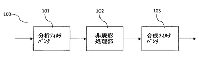
図1は、1次の周波数領域(FD)ハーモニックトランスポーザ100の処理例を示す。基本形態において、T次のハーモニックトランスポーザは、理論的には、入力信号の全ての信号成分をT倍高い周波数に移す(シフトする)装置である。このような処理を周波数領域で実行するために、分析フィルタバンク(又は変換部)101は、入力信号を時間領域から周波数領域へ変換し、分析サブバンド又は分析サブバンド信号と言及される複素サブバンド又はサブバンド信号を出力する。分析サブバンド信号は非線形処理部102に与えられ、非線形処理部102は選択されたトランスポジション次数Tに従って位相及び/又は振幅を修正又は調整する。典型的には、非線形処理部はある数のサブバンド信号を出力し、それは入力サブバンド信号の数、すなわち分析サブバンド信号の数に等しい。しかしながら、高級な(advanced)非線形処理部の場合、入力サブバンド信号数とは異なる数のサブバンド信号を出力することが望ましい。特に、1つの出力サブバンド信号を生成するために、2つのサブバンド信号が非線形処理部で処理されてもよい。この点については以下において詳述する。合成サブバンド(analysis subband)又は合成サブバンド(synthesis subbad)信号と言及される修正されたサブバンド又はサブバンド信号は合成フィルタバンク103(変換部)に与えられ、合成フィルタバンクは、サブバンド信号を周波数領域から時間領域へ変換し、トランスポジションの処理がなされた時間領域信号を出力する。
FIG. 1 shows a processing example of a primary frequency domain (FD)
典型的には、フィルタバンクの各々は、ヘルツで表現される物理周波数分解能と秒で表現される時間ストライドパラメータ(time stride parameter)とを有する。これら2つのパラメータ(すなわち、周波数分解能及びタイムストライド)は、選択されたサンプリングレートにおけるフィルタバンクの離散時間パラメータを規定する。分析及び合成フィルタバンクの物理的時間ストライドパラメータ(すなわち、例えば秒である時間単位で測定される時間ストライドパラメータ)が一致するように選択することで、トランスポーザ100の出力信号は、入力信号と同じサンプリングレートを有するようになる。更に、非線形処理部102を省略することで、出力における入力信号の完全な再構築が達成される。これは、分析及び合成フィルタバンクについて注意深い設計を要する。一方、出力サンプリングレートが入力サンプリングレートと異なるように選択される場合、サンプリングレートの変換が行われる。この動作モードは、例えば、所望の出力帯域幅が入力サンプリングレートの半分より大きい信号トランスポジションを適用する場合、すなわち所望の出力帯域幅が入力信号のナイキスト周波数を超える場合に必要になる。
Each filter bank typically has a physical frequency resolution expressed in hertz and a time stride parameter expressed in seconds. These two parameters (ie, frequency resolution and time stride) define the filter bank's discrete time parameters at the selected sampling rate. By choosing to match the physical time stride parameters of the analysis and synthesis filter bank (i.e., time stride parameters measured in units of time, for example seconds), the output signal of the
図2は、異なる次数の複数のハーモニックトランスポーザ201-1,...,201-Pを含むマルチプル(multiple)トランスポーザシステム200の例を示す。トランスポジションの処理が施される入力信号は、P個の個々のトランスポーザ201-1,201-2,...,201-Pのバンクに与えられる。個々のトランスポーザ201-1,201-2,...,201-Pは図1に関連して説明したような入力信号のハーモニックトランスポジションを実行する。典型的には、個々のトランスポーザ201-1,201-2,...,201-Pの各々は異なるトランスポジション次数Tのハーモニックトランスポジションを実行する。一例として、トランスポーザ201-1は次数T=1のトランスポジションを実行し、トランスポーザ201-2は次数T=2のトランスポジションを実行し、そしてトランスポーザ201-Pは次数T=Pのトランスポジションを実行してもよい。その成果、すなわち個々のトランスポーザ201-1,201-2,...,201-Pからの出力信号は合成部、加算部又はコンバイナ202において加算され、加算されたトランスポーザ出力を生成する。
FIG. 2 shows an example of a
トランスポーザ201-1,201-2,...,201-Pの各々は図1に示されているような分析及び合成フィルタバンクを要することに留意すべきである。更に、個々のトランスポーザ201-1,201-2,...,201-Pは、典型的には、処理される入力信号のサンプリングレートを異なる量だけ変更する。一例として、トランスポーザ201-1の出力信号のサンプリングレートは、トランスポーザ201-Pに対する入力信号のサンプリングレートよりもP倍高い。これは、トランスポーザ201-Pの中で使用されている帯域幅拡張因子(bandwidth expansion factor)Pに起因し、すなわち分析フィルタバックよりもP倍多いサブチャネルを有する合成フィルタバンクを使用することに起因する。これを実行するため、サンプリングレート及びナイキスト周波数は因子Pにより増加させられている。その結果、個々の時間領域信号は、合成部202において様々な出力信号の合成を可能にするために、サンプリングし直される(リサンプリングされる)必要がある。時間領域信号のリサンプリングは、個々のトランスポーザ201-1,201-2,...,201-P各々に対する入力信号又は出力信号において実行可能である。
It should be noted that each of the transposers 201-1, 201-2,..., 201-P requires an analysis and synthesis filter bank as shown in FIG. Further, the individual transposers 201-1, 201-2,..., 201-P typically change the sampling rate of the input signal being processed by a different amount. As an example, the sampling rate of the output signal of the transposer 201-1 is P times higher than the sampling rate of the input signal to the transposer 201-P. This is the use of transposer bandwidth extension factor that is used in the 201-P (bandwidth expansion factor) due to P, i.e. a synthesis filter bank having P times more subchannels than the analysis filter back caused by. To do this, the sampling rate and Nyquist frequency are increased by a factor P. As a result, the individual time domain signals need to be resampled (resampled) in order to allow the combining
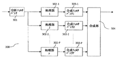
図3は、共通する分析フィルタバンクを使用して、いくつもの次数のトランスポジションを実行するマルチプルハーモニックトランスポーザ又はマルチプルトランスポーザシステム300の構成例を示す。マルチプルトランスポーザ300の設計の最初の段階では、全てのトランスポーザ201-1,201-2,...,201-Pの分析フィルタバンク(図1における参照符号101)が、同一でありかつ単独の分析フィルタバンク301で代替できるように、図2の個々のトランスポーザ201-1,201-2,...,201-Pを設計する。その結果、時間領域入力信号は、単一の一群の周波数領域サブバンド信号(すなわち、単一の一群の分析サブバンド信号)に変換される。これらのサブバンド信号は、様々な次数のトランスポジションに備えて様々な非線形処理部302-1,302-2,...,302-Pに与えられる。図1に関して説明したように、非線形処理部はサブバンド信号の位相及び/又は振幅の修正部を有し、この修正は異なる次数のトランスポジションについては異なっている。従って、別様に修正されたサブバンド信号又はサブバンドは、異なる非線形処理部302-1,302-2,...,302-Pに対応する異なる合成フィルタバンク303-1,303-2,...,303-Pにそれぞれ与えられる。その成果として、異なるトランスポジションが施された時間領域出力信号が得られ、それらは合成部304において加算され、加算されたトランスポーザ出力が得られる。
FIG. 3 shows an example configuration of a multiple harmonic transposer or
様々なトランスポジション次数に対応する合成フィルタバンク303-1,303-2,...,303-Pが、例えば様々な帯域幅拡張度を利用することで、様々なサンプリングレートで動作する場合、様々な合成フィルタバンク303-1,303-2,...,303-Pの時間領域出力信号は、合成部304で加算される前に、P個の出力信号を同じ時間単位又は時間グリッドに整合させるために様々にリサンプリングされる必要があることに、留意を要する。
Synthesis filter banks 303-1, 303-2,... Corresponding to various transposition orders. . . , 303-P may operate at various sampling rates, for example, using various bandwidth extensions, for example, various synthesis filter banks 303-1, 303-2,. . . , 303-P time domain output signals need to be variously resampled to match the P output signals to the same time unit or time grid before being summed by the
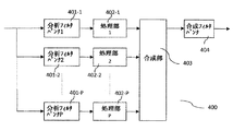
図4は、共通する合成フィルタバンク404を使用して、複数の次数のトランスポジションを利用したマルチハーモニックトランスポーザシステム400の構成例を示す。マルチプルトランスポーザ400の設計の最初の段階では、全てのトランスポーザの合成フィルタバンクが、同一でありかつ単独の合成フィルタバンク404で代替できるように、図2の個々のトランスポーザ201-1,201-2,...,201-Pを設計する。図3に示す例と同様に、非線形処理部402-1,402-2,...,402-Pはトランスポジション次数各々について異なることに留意を要する。更に、分析フィルタバンク401-1,401-2,...,401-Pは異なるトランスポジション次数に対して異なっている。従って、P個の分析フィルタバンク401-1,401-2,...,401-Pの一群は、P個の群の分析サブバンド信号を決定する。これらのP個の群の分析サブバンド信号は対応する非線形処理部402-1,402-2,...,402-Pに与えられ、P個の群の修正されたサブバンド信号を出力する。これらP個の群のサブバンド信号は合成部403において周波数領域で合成され、合成された一群のサブバンド信号を、単一の合成フィルタバンク404の入力として出力する。合成部403における信号の合成は、別様に処理されたサブバンド信号を異なるサブバンドレンジに与えること、及び/又はサブバンド信号の寄与を重複する(オーバーラップする)サブバンドレンジに重ね合わせることを含む。言い換えれば、異なるトランスポジション次数で処理された様々な分析サブバンド信号は、重複する周波数範囲をカバーする。その場合、重ね合わせの個々の寄与が合成部403により合成される(すなわち、加算される及び/又は平均化される)。マルチプルトランスポーザ400の時間領域出力信号が共通の合成フィルタバンク404から得られる。上述したのと同様に、分析フィルタバンク401-1,401-2,...,401-Pが異なるサンプリングレートで動作する場合、様々な分析フィルタバンク401-1,401-2,...,401-Pに対する時間領域信号入力は、様々な非線形処理部402-1,402-2,...,402-Pの出力信号を同じ時間単位に整合させるようにリサンプリングされる必要がある。
FIG. 4 shows a configuration example of a
図5は、1つの共通する分析フィルタバンク501及び1つの共通する合成フィルタバンク504を有し、複数の次数のトランスポジションを利用行うマルチハーモニックトランスポーザシステム500の例を示す。この場合、図2の個々のトランスポーザ201-1,201-2,...,201-Pは、P個のハーモニックトランスポーザの分析フィルタバンク及び合成フィルタバンクの双方が同じであるように設計される。異なるP個のハーモニックトランスポーザに関する同じ分析及び合成フィルタバンクの条件が合致していた場合、同じフィルタバンクは、1つの分析フィルタバンク501及び1つの合成フィルタバンク504により置換できる。アドバンスト非線形処理部502-1,502-2,...,502-Pは、合成部503において合成される様々な寄与成分を出力し、合成部は、合成フィルタバンク504の個々のサブバンドに対する合成された入力を生成する。図4に示すマルチハーモニックトランスポーザ400と同様に、合成部503における信号の合成は、非線形処理部502-1,502-2,...,502-Pの別様に処理された信号を様々なサブバンドレンジに供給すること、及び寄与する複数の出力を重複する複数のサブバンドレンジに重ね合わせることを含む。
FIG. 5 shows an example of a
上述したように、非線形処理部102は、典型的には、入力におけるサブバンド数に対応する数のサブバンドを出力において提供する。非線形処理部102は、典型的には、使用されるトランスポジション次数Tに従ってサブバンド又はサブバンド信号の位相及び/又は振幅を修正する。一例として、入力におけるサブバンドは出力においてT倍高い周波数のサブバンドンに変換され、すなわち、非線形処理部102に対する入力において[(k-(1/2))Δf,(k+(1/2))Δf]の範囲内のサブバンド(分析サブバンド)は、非線形処理部102の出力において[(k-(1/2))TΔf,(k+(1/2))TΔf]の範囲内のサブバンド(合成サブバンド)に変換される。ここで、kはサブバンドインデックス数であり、Δfは分析フィルタバンクの周波数分解能である。共通の分析フィルタバンク501及び共通の合成フィルタバンク504を使用できるようにするため、アドバンスト処理部502-1,502-2,...,502-Pの1つ以上は、入力サブバンド数とは異なる数の出力サブバンドを与えるように構成される。一実施形態において、アドバンスト処理部502-1,502-2,...,502-Pに対する入力サブバンド数は、出力サブバンド数のおよそF/T倍である。ここで、Tはアドバンスト処理部のトランスポジション次数であり、Fは以下の説明で導入されるフィルタバンク分解能因子(filter bank resolution factor)である。
As described above,
以下、非線形処理部502-1,502-2,...,502-Pに関するアドバンスト処理部502-1,502-2,...,502-Pの原理を説明する。この目的のため、以下のことを仮定する。 The principle of the advanced processing units 502-1, 502-2,..., 502-P related to the nonlinear processing units 502-1, 502-2,. For this purpose, assume the following:
●分析フィルタバンク及び合成フィルタバンクは同じ物理時間ストライドパラメータΔtを共有している。 The analysis filter bank and the synthesis filter bank share the same physical time stride parameter Δt.
●分析フィルタバンクは物理周波数分解能Δfを有する。 The analysis filter bank has a physical frequency resolution Δf.
●合成フィルタバンクは物理周波数分解能FΔfを有し、分解能因子Fは1以上の整数である(F≧1)。 The synthesis filter bank has a physical frequency resolution FΔf, and the resolution factor F is an integer greater than or equal to 1 (F ≧ 1).
更に、複数のフィルタバンクは均等に又は整数倍の位置に(evenly)用意されており、すなわちインデックス0のサブバンドはゼロ周波数付近に中心を有し、分析フィルタバンクの中心周波数はkΔfで与えられることが仮定され、分析サブバンドインデックスkはk=0,1,...,LA-1であり、LAは分析フィルタバンクのサブバンド数である。合成フィルタバンクの中心周波数はnFΔfにより与えられ、合成サブバンドインデックスnは、n=0,1,...,Ls-1であり、Lsは合成フィルタバンクのサブバンド数である。 Furthermore, a plurality of filter banks are provided evenly or evenly in an integer multiple, that is, the subband with index 0 is centered around zero frequency, and the center frequency of the analysis filter bank is given by kΔf. And the analysis subband index k is k = 0, 1,..., L A −1, and L A is the number of subbands in the analysis filter bank. The center frequency of the synthesis filter bank is given by nFΔf, the synthesis subband index n is n = 0, 1,..., L s −1, and L s is the number of subbands in the synthesis filter bank.
図1に示されるような次数T≧1の従来のトランスポジションを実行する場合、分解能因子FはF=Tであるように選択され、非線形処理部の分析サブバンドkは同じインデックスn=kの分析サブバンドにマッピングされる。非線形処理部102は典型的にはサブバンド又はサブバンド信号の位相に因子Tを乗算し、すなわちフィルタバンクのサブバンドの各サンプルに対して、次のように書くことができる:
θs(k)=TθA(k) (1)
θA(k)は分析サブバンドkのサンプルの位相であり、θs(k)は合成サブバンドkのサンプルの位相である。サブバンドのサンプルの大きさ又は振幅は、修正されないように維持されてもよいし、或いは一定のゲインファクタの分だけ増加又は減少させられてもよい。Tは整数であるので、(1)の数式の処理は位相角の定義に依存しない。
When performing a conventional transposition of order T ≧ 1 as shown in FIG. 1, the resolution factor F is selected to be F = T, and the analysis subband k of the nonlinear processor is the same index n = k Maps to analysis subband. The
θ s (k) = Tθ A (k) (1)
θ A (k) is the phase of the sample in analysis subband k, and θ s (k) is the phase of the sample in synthesis subband k. The subband sample size or amplitude may be kept uncorrected, or may be increased or decreased by a fixed gain factor. Since T is an integer, the processing of equation (1) does not depend on the definition of the phase angle.
分解能因子Fがトランスポジション次数Tに等しい場合(すなわち、F=Tである場合)、合成フィルタバンクの周波数分解能(すなわち、FΔf)はトランジション次数Tに依存する。従って、分析又は合成の処理段において、異なるフィルタバンクについて異なるトランスポジション次数Tを使用する必要がある。これは、トランスポジション次数Tが、物理周波数分解能の程度、すなわち分析フィルタバンクの周波数分解能Δfの程度及び合成フィルタバンクの周波数分解能FΔfを規定していることに起因する。 When the resolution factor F is equal to the transposition order T (ie, F = T), the frequency resolution (ie, FΔf) of the synthesis filter bank depends on the transition order T. It is therefore necessary to use different transposition orders T for different filter banks in the analysis or synthesis processing stage. This is because the transposition order T defines the degree of physical frequency resolution, that is, the degree of frequency resolution Δf of the analysis filter bank and the frequency resolution FΔf of the synthesis filter bank.
複数の異なるトランスポジション次数T について共通の分析フィルタバンク501及び共通の合成フィルタバンク504を使用できるようにするため、本願では、合成フィルタバンクの周波数分解能をFΔfに設定することが提案される、すなわち合成フィルタバンク504の周波数分解能をトランスポジション次数Tに依存しないようにすることが提案される。従って、分析及び合成フィルタバンクの物理周波数分解能の程度を示す分解能因子Fが、F=Tという関係式に従う必要がない場合に、次数Tのトランスポジションを如何にして実行するかが問題になる。
In order to be able to use a common
上記において説明したように、ハーモニックトランスポーザの原理によれば、中心周波数がnFΔfである合成フィルタバンクのサブバンドnに対する入力は、1/T倍低い中心周波数(nFΔf/T)における分析サブバンドにより決定される。分析サブバンドの中心周波数は、分析サブバンドインデックスkを利用すれば、kΔfのように特定される。分析サブバンドインデックスの中心周波数の双方の表現(すなわち、nFΔf/T及びkΔf)は等しい(対応させてよい)。nが整数であることを考慮すると、nF/Tという表現の有理数は、整数の分析サブバンドインデックスkとそれ以外の部分r(r∈{0,1/T,2/T,...,(T-1)/T})との和として、次のように表現することができる:
nF/T=k+r (2)
従って、合成サブバンドインデックスnの合成サブバンドに対する入力は、次数Tのトランスポジションを用いて、数式(2)により与えられるインデックスの分析サブバンド又はサブバンドkから導出されることが、保証される。nF/Tは有理数であるので、余り又は剰余rは0に等しい値ではなく、値k+rは分析サブバンドインデックスkより大きくかつ分析サブバンドインデックスk+1より小さい。従って、合成サブバンドインデックスnの合成サブバンドに対する入力は、次数Tのトランスポジションを用いて、分析サブバンドインデックスk及びk+1の分析サブバンドから導出され、kは数式(2)により与えられる。
As explained above, according to the principle of the harmonic transposer, the input to the subband n of the synthesis filter bank whose center frequency is nFΔf is based on the analysis subband at the center frequency (nFΔf / T) which is 1 / T times lower. It is determined. The center frequency of the analysis subband is specified as kΔf using the analysis subband index k. Both representations (ie, nFΔf / T and kΔf) of the center frequency of the analysis subband index are equal (may correspond). Considering that n is an integer, the rational number nF / T is represented by an integer analysis subband index k and the other part r (r∈ {0,1 / T, 2 / T, ..., (T-1) / T}) and can be expressed as:
nF / T = k + r (2)
Therefore, it is guaranteed that the input to the composite subband of the composite subband index n is derived from the analysis subband or subband k of the index given by equation (2) using the order T transposition. . Since nF / T is a rational number, the remainder or remainder r is not a value equal to 0, and the value k + r is greater than the analysis subband index k and less than the analysis subband index k + 1. Thus, the input for the composite subband with composite subband index n is derived from the analysis subbands with analysis subband indices k and k + 1 using the transposition of order T, where k is given by equation (2) .
上記の分析の結果として、非線形処理部502-1,502-2,...,502-Pにおいて実行される高度な非線形処理(アドバンスト非線形処理)は、概して、出力を合成サブバンドnに与えるインデックスk及びk+1の2つの隣接する分析サブバンドを考慮することを含む。トランスポジション次数Tの場合、非線形処理部502-1,502-2,...,502-Pにより実行される位相調整は、従って、次の線形補間法により決定されてもよい:
θs(n)=T(1-r)θA(k)+TrθA(k+1) (3)
ここでθA(k)は分析サブバンドkのサンプルの位相であり、θA(k+1)は分析サブバンドk+1のサンプルの位相であり、θs(k)は合成サブバンドnのサンプルの位相である。すなわち、剰余rが0に近い場合、k+rの値はkに近くなり、その場合、合成サブバンドのサンプルの位相に主に寄与するものは、サブバンドkの分析サブバンドのサンプルの位相から得られる。一方、剰余rが1に近い場合、k+rの値はk+1に近くなり、その場合、合成サブバンドのサンプルの位相に主に寄与するものは、サブバンドk+1の分析サブバンドのサンプルの位相から得られる。数式(3)の位相調整が明確に規定されかつ位相角の定義に依存しないように、位相乗算因子T(1-r)及びTrは何れも整数であることに留意を要する。
As a result of the above analysis, the advanced nonlinear processing (advanced nonlinear processing) executed in the nonlinear processing units 502-1, 502-2,..., 502-P generally has an index k that gives an output to the synthesized subband n. And considering two adjacent analysis subbands of k + 1. For the transposition order T, the phase adjustment performed by the nonlinear processing units 502-1, 502-2,..., 502-P may therefore be determined by the following linear interpolation method:
θ s (n) = T (1-r) θ A (k) + Trθ A (k + 1) (3)
Where θ A (k) is the phase of the sample in analysis subband k, θ A (k + 1) is the phase of the sample in analysis subband k + 1, and θ s (k) is the combined subband n Is the phase of the sample. That is, when the residue r is close to 0, the value of k + r is close to k, and in this case, what mainly contributes to the phase of the synthesized subband sample is the phase of the subband k analysis subband sample Obtained from. On the other hand, when the remainder r is close to 1, the value of k + r is close to k + 1, and in this case, the main contribution to the phase of the synthesized subband samples is the analysis subband of subband k + 1 Obtained from the phases of the samples. It should be noted that the phase multiplication factors T (1-r) and Tr are both integers so that the phase adjustment of Equation (3) is clearly specified and does not depend on the definition of the phase angle.
サブバンドサンプルの大きさを考慮して、合成サブバンドサンプルの大きさを判定するために、以下の幾何平均値が選択される:
aS(n)=aA(k)(1-r)aA(k+1)r (4)
aS(n)は合成サブバンドnのサンプルの大きさを示し、aA(k)は分析サブバンドのサンプルの大きさを示し、aA(k+1)は分析サブバンドk+1のサンプルの大きさを示す。
Considering the size of the subband samples, the following geometric mean values are selected to determine the size of the synthesized subband samples:
a S (n) = a A (k) (1-r) a A (k + 1) r (4)
a S (n) indicates the sample size of the synthetic subband n, a A (k) indicates the sample size of the analysis subband, and a A (k + 1) indicates the analysis
フィルタバンクが半整数倍の位置に(oddly)用意されていた場合、分析フィルタバンクの中心周波数は(k+(1/2))Δfにより与えられ、k=0,1,...,LA-1であり、合成フィルタバンクの中心周波数は(n+(1/2))FΔfにより与えられ、n=0,1,...,LA-1であり、上記の数式(2)に対応する数式は、トランスポジション後の合成フィルタバンクの中心周波数(n+(1/2))FΔf/Tと分析フィルタバンクの中心周波数(k+(1/2))Δfとを等しく置くことで導出される。整数インデックスk及び剰余r∈[0,1]を考慮すると、半整数倍の位置にあるフィルタバンクについて以下の数式が導出される:
(n+(1/2))F/T=k+1/2+r (5)
T-F、すなわちトランスポジション次数及び分解能因子の差分が偶数(even)である場合、T(1-r)及びTrは双方とも整数であり、数式(3)及び(4)の補間の数式を使用できることが分かる。
If the filter bank is provided (oddly) at a half-integer multiple, the center frequency of the analysis filter bank is given by (k + (1/2)) Δf, and k = 0,1, ..., L A -1, and the center frequency of the synthesis filter bank is given by (n + (1/2)) FΔf, where n = 0,1, ..., L A -1 and corresponds to equation (2) above The mathematical expression to be derived is derived by placing the center frequency (n + (1/2)) FΔf / T of the synthesized filter bank after transposition equal to the center frequency (k + (1/2)) Δf of the analysis filter bank. . Considering the integer index k and the remainder r∈ [0,1], the following formula is derived for a filter bank located at a half-integer multiple:
(n + (1/2)) F / T = k + 1/2 + r (5)
If TF, i.e. the difference between the transposition order and resolution factor is even, T (1-r) and Tr are both integers, and the interpolation formulas in equations (3) and (4) can be used. I understand.
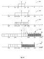
図5bは、分析サブバンドを合成サブバンドに対応付ける様子を示す。図5bはT=1ないしT=4の4つの異なるトランスポジション次数に関する4つのマッピング例を示す。各々の図は、ソースビン510(すなわち、分析サブバンド)がターゲットビン530(すなわち、合成サブバンド)にどのようにマッピングされるかを示す。図示の簡明化のため、分解能因子Fは1であるとする。言い換えれば、図5bは、数式(2)及び(3)を用いて分析サブバンド信号を合成サブバンド信号にマッピングする様子を示す。図示の例の場合、F=1及び最大トランスポジション次数P=4と共に、分析/合成フィルタバンクは整数倍毎に(evenly)設定されている。 FIG. 5b shows how analysis subbands are associated with synthetic subbands. FIG. 5b shows four mapping examples for four different transposition orders from T = 1 to T = 4. Each figure shows how source bins 510 (ie, analysis subbands) are mapped to target bins 530 (ie, synthesis subbands). For the sake of simplicity, it is assumed that the resolution factor F is 1. In other words, FIG. 5b shows how the analysis subband signal is mapped to the synthesized subband signal using equations (2) and (3). In the case of the illustrated example, the analysis / synthesis filter bank is set evenly every integer multiple, with F = 1 and the maximum transposition order P = 4.
図示の例の場合、数式(2)は、n/T=k+r のように書ける。従って、トランスポジション次数T=1の場合、インデックスkの分析サブバンドは対応する合成サブバンドnにマッピングされ、剰余rはゼロである。これは図5bに示されており、ソースビン511はターゲットビンに531に1対1に対応付けられている。
In the case of the illustrated example, Equation (2) can be written as n / T = k + r. Therefore, when the transposition order T = 1, the analysis subband of index k is mapped to the corresponding synthesis subband n, and the remainder r is zero. This is shown in FIG. 5b, where the
トランスポジション次数T=2の場合、剰余rは0及び1/2の値をとり、ソースビンは複数のターゲットビンに対応付けられる。逆の観点から見れば、ターゲットビン532、535の各々は高々2つのソースビンから寄与を受けている、と言える。このことは図5bにおいて、ターゲットビン535がソースビン512及び515から寄与を受けているようなことで示されている。しかしながら、ターゲットビン532はソースビン512からの寄与しか受けていない。ターゲットビン535が偶数インデックスn(例えば、n=10)を有するとすると、数式(2)は、ターゲットビン532がインデックスk=n/2(すなわち、k=5)と共にソースビン512から寄与を受けることを示す。この場合、剰余rはゼロであり、すなわちインデックスk+1(すなわち、k+1=6)のソースビン515からの寄与はない。奇数インデックスn(例えば、n=11)のターゲットビン535の場合、状況は変わる。この場合、数式(2)は、ターゲットビン535がソースビン512(インデックスk=5)及びソースビン515(インデックスk+1=6)から寄与を受けることを示す。このことは、高次のトランスポジション次数T(例えば、図5bに示されているようなT=3及びT=4)についても同様である。
When the transposition order T = 2, the remainder r takes values of 0 and 1/2, and the source bin is associated with a plurality of target bins. From the opposite viewpoint, it can be said that each of the
F=2の場合、数式(2)は2n/T=k+rのように書くことができ、この場合については図5cに示されている。トランスポジション次数T=2の場合、インデックスkの分析サブバンドは対応する合成サブバンドnにマッピングされ、剰余rは常にゼロである。これは、ソースビン521がターゲットビン514に1対1にマッピングされていることから分かる。
For F = 2, equation (2) can be written as 2n / T = k + r, which is shown in FIG. 5c. For transposition order T = 2, the analysis subband of index k is mapped to the corresponding synthesis subband n, and the remainder r is always zero. This can be seen from the fact that the
トランスポジション次数T=3の場合、剰余rは0、1/3、2/3の値をとり、ソースビンは複数のターゲットビンに対応付けられる。逆の観点から見れば、ターゲットビン542、545の各々は高々2つのソースビンから寄与を受けている、と言える。このことは図5cにおいて、ターゲットビン545がソースビン522及び525から寄与を受けているようなことで示されている。ターゲットビン545が例えばインデックスn=8を有するとすると、数式(2)は、k=5及びr=1/3であることを示し、ターゲットビン545がソースビン522(インデックスk=5)及びソースビン525(インデックスk+1=6)から寄与を受けることを示す。しかしながら、インデックスn=9のターゲットビン546の場合、剰余rはゼロになり、ターゲットビン546はソースビン525からの寄与しか受けない。このことは、高次のトランスポジション次数T(例えば、図5cに示されているようなT=4)についても同様である。
When the transposition order T = 3, the remainder r takes values of 0, 1/3, and 2/3, and the source bin is associated with a plurality of target bins. From the opposite viewpoint, it can be said that each of the
上記のアドバンスト非線形処理の更なる説明は次のようになる。アドバンスト非線形処理は、所与の次数Tのトランスポジションを行うことと、トランスポジション後のサブバンド信号を共通合成フィルタバンクにより規定される周波数グリッド(すなわち、周波数グリッドFΔf)にマッピングすることとの組み合わせとして理解できる。この解釈を説明するため、再び図5b又は5cを参照する。ただし、ソースビン510又は520は、トランスポジション次数Tを用いて分析サブバンドから導出された合成サブバンドであるとする。これらの合成サブバンドはTΔfにより与えられる周波数グリッドを有する。ターゲットビン530又は540により与えられる所定の周波数グリッドFΔfにおける合成サブバンドを生成するために、ソースビン510又は520(すなわち、周波数グリッドTΔfを有する合成サブバンド)は、所定の周波数グリッドFΔfにマッピングされる必要がある。これは、1つ以上のソースビン510又は520(すなわち、周波数グリッドTΔfにおける合成サブバンド信号)を補間し、ターゲットビン530又は540(すなわち、周波数グリッドFΔfにおける合成サブバンド信号)を決定することで行われる。好適実施形態の場合、線形補間が使用され、補間のウェイト(重み係数)は、ターゲットビン530又は540の中心周波数と対応するソースビン510又は520との間の差分の逆数に比例する。一例として、差分がゼロであった場合のウェイトは1であり、差分がTΔfであった場合のウェイトは0である。
A further description of the above advanced nonlinear processing is as follows. Advanced nonlinear processing is a combination of performing transposition of a given order T and mapping the subband signal after transposition to a frequency grid (ie, frequency grid FΔf) defined by a common synthesis filter bank. Can be understood as To illustrate this interpretation, reference is again made to FIG. 5b or 5c. However,
要するに、いくつかの分析サブバンドのトランスポジションによる合成サブバンドへの寄与を決定できるようにする非線形処理法が説明されている。その非線形処理法は、様々なトランスポジション次数に対する単一の共通の分析及び合成サブバンドフィルタバンクを使用できるようにし、これにより複数のハーモニックトランスポーザの複雑な演算を大幅に減少させることができる。 In summary, non-linear processing methods have been described that allow the determination of the contribution to the composite subband by the transposition of several analytical subbands. The non-linear processing method allows the use of a single common analysis and synthesis subband filter bank for various transposition orders, which can greatly reduce the complex operations of multiple harmonic transposers.
以下、マルチハーモニックトランスポーザ又はハーモニックトランスポーザシステムのいくつかの実施形態を説明する。本願のリファレンスに含めている特許文献1(WO98/57436)等に示されているSBR(スペクトルバンドレプリケーション)のような高周波再構築(high frequency reconstruction: HFR)を使用するオーディオソース符号化/復号化システムの場合における典型的な処理では、コアデコーダ(すなわち、オーディオ信号の低周波成分のデコーダ)が、時間領域信号をHFRモジュール又はHFRシステム(すなわち、オーディオ信号の高周波成分の再構築を実行するモジュール又はシステム)に出力する。低周波数成分は、低周波数成分及び高周波数成分を含む元のオーディオ信号の帯域幅の半分より狭い帯域幅を有する。従って、低バンド信号(低帯域信号)と言及される低周波成分を含む時間ドメイン信号(時間領域信号)は、オーディオ符号化/復号化システムの最終的な出力信号のサンプリングレートの半分でサンプリングされてよい。その場合、HFRモジュールは、コア信号を出力信号に加えることを支援するように、コア信号(すなわち、低バンド信号)を、サンプリング周波数の2倍に効率的にサンプリングし直す(リサンプリングする)必要がある。したがって、HFRモジュールにより適用されるいわゆる帯域幅拡張因子(bandwidth extension factor)は2に等しい。 In the following, several embodiments of a multi-harmonic transposer or a harmonic transposer system will be described. Audio source encoding / decoding using high frequency reconstruction (HFR) such as SBR (spectral band replication) shown in Patent Document 1 (WO98 / 57436) included in the reference of the present application In a typical process in the case of a system, the core decoder (i.e., the decoder of the low frequency component of the audio signal) is the HFR module or module that performs the reconstruction of the high frequency component of the audio signal (i.e. Or output to the system). The low frequency component has a bandwidth that is narrower than half the bandwidth of the original audio signal including the low frequency component and the high frequency component. Therefore, time domain signals (time domain signals) containing low frequency components, referred to as low band signals (low band signals), are sampled at half the sampling rate of the final output signal of the audio encoding / decoding system. It's okay. In that case, the HFR module needs to efficiently resample (resample) the core signal (i.e., the low-band signal) to twice the sampling frequency to help add the core signal to the output signal. There is. Therefore, the so-called bandwidth extension factor applied by the HFR module is equal to 2.
HFR生成信号と言及される高周波成分の生成後、HFR生成信号は、元の信号の高周波成分(すなわち、エンコードされた本来の信号の高周波成分)にできるだけ合致させるように動的に調整される。この調整は、典型的には、送信側の情報を利用するいわゆるHFRプロセッサにより実行される。送信側情報は元の信号の高周波成分のスペクトルエンベロープに関する情報を含み、HFR生成信号の調整はHFR生成信号のスペクトルエンベロープの調整を含む。 After generating the high-frequency component is referred to as HFR generation signal, HFR generation signal is dynamically adjusted so that as much as possible to meet the high-frequency components of the original signal (i.e., the high frequency component of the encoded original signal) . This adjustment is typically performed by a so-called HFR processor that utilizes information on the transmitting side. The transmission side information includes information related to the spectrum envelope of the high frequency component of the original signal, and the adjustment of the HFR generation signal includes adjustment of the spectrum envelope of the HFR generation signal.
送信側情報に従ってHFR生成信号の調整を実行するために、HFR生成信号はマルチチャネル直交ミラーフィルタ(Quadrature Mirror Filter: QMF)バンクにより分析され、このマルチチャネルQMFバンクはHFR生成信号のスペクトルQMFサブバンド信号を提供する。そして、HFRプロセッサは、分析QMFバンクから取得したスペクトルQMFサブバンド信号におけるHFR生成信号の調整を実行する。最終的に、調整されたQMFサブバンド信号は分析QMFバンクにおいて合成される。サンプリング周波数の変更を実行するために、例えば、低バンド信号のサンプリング周波数からオーディオ符号化/復号化システムの出力信号のサンプリング周波数へサンプリング周波数を2倍にするために、分析QMFバンド数は合成QMFバンド数と異なっていてもよい。一実施形態において、分析QMFバンクは32個のサブバンド信号を生成し、合成QMFバンクバンクプロセッサが64個のQMFサブバンドを処理し、これにより2倍のサンプリング周波数を提供してもよい。典型的には、トランスポーザの分析及び/又は合成フィルタバンクは何百もの分析及び/又は合成サブバンドを生成し、QMFバンクよりも非常に高い周波数分解能を提供してよいことに、留意を要する。 To perform the adjustment of the HFR generated signal according to the transmitter information, the HFR generated signal is analyzed by a multi-channel quadrature mirror filter (QMF) bank, which is the spectral QMF subband of the HFR generated signal. Provide a signal. The HFR processor then adjusts the HFR generation signal in the spectral QMF subband signal obtained from the analysis QMF bank. Finally, the adjusted QMF subband signal is synthesized in the analysis QMF bank. To perform the sampling frequency change, for example, to double the sampling frequency from the sampling frequency of the low-band signal to the sampling frequency of the output signal of the audio encoding / decoding system, the analysis QMF band number is the combined QMF It may be different from the number of bands. In one embodiment, the analysis QMF bank may generate 32 subband signals, and a combined QMF bank bank processor may process 64 QMF subbands, thereby providing twice the sampling frequency. Note that typically a transposer analysis and / or synthesis filter bank may generate hundreds of analysis and / or synthesis subbands and provide much higher frequency resolution than a QMF bank. .
図6のHFRシステム600には、信号の高周波成分を生成する処理例が示されている。送信されたビットストリームはコアデコーダ601で受信され、サンプリング周波数fsにおいてコアデコーダはデコードされた出力信号の周波数成分を提供する。サンプリング周波数fsの低周波成分は個々の様々なトランスポーザ602-1,...,602-Pに入力され、単独のトランスポーザ各々は図1に示されているようなトランスポジション次数T=2,...,Pの単独のトランスポーザに対応する。T=1,2,...,Pに関するトランスポジション後の個々の信号は個々の分析QMFバンク603-1,...,603-Pの特定のインスタンスに別々に与えられる。低周波成分は次数T=1のトランスポジション信号と考えられていることに留意を要する。コア信号のリサンプリング(すなわち、サンプリング周波数fsにおける低周波成分のリサンプリング)は、ダウンサンプリングされたQMFバンク603-1(典型的には、64チャネルではなく32チャネルを有する)を用いて低周波成分をフィルタリングすることで行われる。その成果として32個のサブバンド信号が生成され、各QMFサブバンド信号はサンプリング周波数fs/32を有する。
The
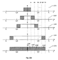
サンプリング周波数fsにおいて次数T=2のトランスポジションによる信号への影響は図12aに示すような周波数ダイアグラムにより表現される。周波数ダイアグラム1210は帯域幅がBHzのトランスポーザ602-2に対する入力信号を示す。入力信号は分析フィルタバンクにより複数の分析サブバンド信号に分割(区分又はセグメント化)される。これは周波数バンド1211へのセグメント化により表現される。分析サブバンド信号は、T=2倍高い周波数範囲へ移され(トランスポジションされ)、サンプリグング周波数は2倍にされる。その結果の周波数領域信号は周波数ダイアグラム1220に示されており、周波数ダイアグラム1220は周波数ダイアグラム1210と同じ周波数スケールを有する(1目盛り又は1単位は同じである)。サブバンド1211はサブバンド1221にトランスポジションされていることが分かる。トランスポジションの処理は破線矢印で示されている。更に、トランスポジション後のサブバンド信号の周期的スペクトル1222が周波数ダイアグラム1220に示されている。代替的に、トランスポジションの処理は周波数ダイアグラム1230のように示されてもよく、この場合、周波数軸がスケール調整され、すなわちトランスポジション因子T=2が乗算されている。言い換えれば、周波数ダイアグラム1230はT=2倍大きなスケールによる周波数ダイアグラム1220に対応する。サブバンド信号1231の各々はセグメント1211の2倍の帯域幅を有する。これは、入力信号よりもT=2倍高いサンプリングレート(すなわち、2fsのサンプリングレート)を有するトランスポーザ602-2の出力信号となるが、信号の時間的な持続期間は不変のままである。
The influence on the signal by the transposition of the order T = 2 at the sampling frequency fs is expressed by a frequency diagram as shown in FIG. 12a. Frequency diagram 1210 shows the input signal to transposer 602-2 with a bandwidth of BHz. The input signal is divided (segmented or segmented) into a plurality of analysis subband signals by an analysis filter bank. This is represented by segmentation into
図6に示されているように及び上記において説明したように、トランスポジション次数T=2の個々のトランスポーザ602-2の出力信号は、2fsのサンプリング周波数を有する。サンプリング周波数がfs/32のQMFサブバンド信号を生成するために、64個のチャネルを有する分析QMFバンク603-2が使用されるべきである。同様に、トランスポジション次数T=Pの個々のトランスポーザ602-Pの出力信号は、Pfsのサンプリング周波数を有する。サンプリング周波数fs/32でQMFサブバンド信号を生成するために、32Pチャネルを有する分析QMFバンク603-2が使用されるべきである。サイズ(すなわち、分析QMFバンク603-1,...,603-P各々のチャネル数)が対応するトランスポーザ602-2,...,602-Pから生じる信号に適合していた場合、分析QMFバンク603-1,...,603-Pの全てのインスタンスからのサブバンド信号は等しいサンプリング周波数を有する。サンプリング周波数fs/32における一群のQMFサブバンド信号はHFR処理モジュール604に与えられ、高周波成分のスペクトル調整は送信側情報に従って実行される。最終的に、調整されたサブバンド信号は64個のチャネルインバース又は合成QMFバンク605により時間領域信号に合成され、これにより、fs/32でサンプリングされたQMFサブバンド信号からサンプリング周波数2fsでデコードされた信号を効率的に生成できる。
As shown in FIG. 6 and as described above, the output signal of each transposer 602-2 with transposition order T = 2 has a sampling frequency of 2fs. In order to generate a QMF subband signal with a sampling frequency of fs / 32, an analysis QMF bank 603-2 with 64 channels should be used. Similarly , the output signal of each transposer 602 -P of transposition order T = P has a sampling frequency of Pfs. In order to generate a QMF subband signal at a sampling frequency fs / 32, an analysis QMF bank 603-2 with 32P channels should be used. Analyze if the size (i.e. the number of channels in each analysis QMF bank 603-1, ..., 603-P) fits the signal originating from the corresponding transposer 602-2, ..., 602-P Subband signals from all instances of QMF banks 603-1,..., 603-P have equal sampling frequencies. A group of QMF subband signals at the sampling frequency fs / 32 is provided to the
上記において説明したように、トランスポーザモジュール602-2,...,602-Pは、それぞれサンプリングレート2fs,...,Pfsのような様々なサンプリングレートの時間領域信号を生成する。トランスポーザモジュール602-2,...,602-Pの出力信号のリサンプリングは、後続の対応するQMF分析バンク603-1,...,603-Pにおいてサブバンドチャネルを「挿入(insert)」又は破棄することで行われる。言い換えれば、トランスポーザモジュール602-2,...,602-Pの出力信号のリサンプリングは、後続の個々の分析QMFバンク603-1,...,603-P及び合成QMFバンク605において異なる数のQMFサブバンドを用いることで行われてよい。従って、QMFバンド602-2,...,602-Pからの出力QMFサブバンド信号は、最終的に合成QMFバンク605に送信される64個のチャネルに適合している必要がある。この適合化又はマッピングは、32個のチャネル分析QMFバンク603-1からの32個のQMFサブバンド信号を、合成又はインバースQMFバンク605の最初の32チャネル(すなわち、32個の低い周波数のチャネル)にマッピング又は加えることで行われる。実際、これは分析QMFバンド603-1を因子2でアップサンプリングすることでフィルタリングされた信号になる。64個のチャネル分析QMFバンク603-2から生じる全てのサブバンド信号は、インバースQMFバンク605の64個のチャネルに直接的にマッピング又は加算されてもよい。分析QMFバンク603-2は合成QMFバンク605と厳密に同じサイズサイズであるという事実の観点からは、トランスポジション後の個々の信号はリサンプルされない。QMFバンク603-3,...,603-Pは、64サブバンド信号を上回る多数の出力QMFサブバンド信号を有する。その場合、低周波側の64個のチャネルが合成QMFバンク605の64チャネルにマッピング又は加算されてよい。高周波側の残りのチャネルは破棄されてもよい。32P個のチャネル分析QMFバンク603-Pの成果として、QMFバンク603-Pによりフィルタリングされた信号は因子P/2でダウンサンプリングされる。従って、トランスポジション次数Pに依存するこのリサンプリングは、同じサンプリング周波数を有する全てのトランスポジション信号になる。
As described above, the transposer modules 602-2,..., 602-P generate time domain signals with various sampling rates such as sampling rates 2fs,. Resampling of the output signal of the transposer modules 602-2, ..., 602-P "inserts" the subband channel in the subsequent corresponding QMF analysis bank 603-1, ..., 603-P. Or by discarding. In other words, the resampling of the output signal of the transposer modules 602-2, ..., 602-P is different in the subsequent individual analysis QMF banks 603-1, ..., 603-P and the
言い換えれば、トランスポーザモジュール602-2,...,602-Pが異なるサンプリングレートの時間領域信号を生成する場合であったとしても、サブバンド信号はHFR処理モジュール604に与えられる場合同じサンプリングレートを有することが望ましい。これは異なるサイズの分析QMFバンク603-3,...,603-Pを使用することで達成され、そのサイズは典型的には32Tであり、Tはトランスポジション因子又はトランスポジション次数である。HFR処理モジュール604及び合成QMFバンク605は典型的には64個のサブバンド信号(すなわち、分析QMFバンク603-1の2倍のサイズ)について処理を行うので、その数を超えるサブバンドインデックスの分析QMFバンク603-3,...,603-Pから生じるすべてのサブバンド信号は破棄されてもよい。トランスポーザ602-2,...,602-Pの出力信号は出力信号のナイキスト周波数を上回る周波数範囲を事実上カバーしているので、これが行われる。残りのサブバンド信号(すなわち、合成QMFバンク605のサブバンドにマッピングさえるサブバンド信号)は、周波数的に重複した(オーバーラップした)トランスポジション信号を生成するように加算されてもよいし(後述する図12b参照)、あるいは別方法により例えば図12c(後述)に示されているように重複していないトランスポジション信号を得るように合成されてもよい。重複しないトランスポジション信号の場合、次数Tのトランスポーザ602-T(T=2,...,P)は典型的には特定の周波数範囲に割り当てられ、トランスポーザ602-Tはその特定の周波数範囲のために周波数成分を排他的に生成する。一実施形態において、トラスポーザ602-Tの専用(個別)の周波数範囲は[(T-1)B,TB]であり、Bはトランスポーザ602-Tに対する入力信号の帯域幅である。その場合、個部の周波数範囲以外のトランスポーザ602-Tの合成サブバンド信号は無視又は破棄される。一方、トランスポーザ602-Tは他のトランスポーザ602-2,...,602-Pの周波数成分と重複する周波数成分を生成してもよい。その場合、それらの重複した周波数成分はQMFサブバンドのドメインで重ね合わせられる。
In other words, even if the transposer modules 602-2, ..., 602-P generate time domain signals with different sampling rates, the subband signals are the same sampling rate when provided to the
上述したように、典型的な実施形態において、マルチプルトランスポーザ602-2,...,602-PはHFRモジュール600の出力信号の高周波成分を生成するのに使用される。トランスポーザ602-2,...,602-Pに対する入力信号(すなわち、出力信号の低周波成分)は帯域幅BHz及びサンプリングレートfsを有し、HFRモジュール600の出力信号はサンプリングレート2fsを有することが、仮定される。従って、高周波成分は周波数範囲[B,fs]をカバーしてもよい。トランスポーザ602-2,...,602-Pの各々は、高周波成分に対する寄与を提供し、それらの寄与は重複していてもよいし及び/又は重複していなくてもよい。図12bでは、様々なトランスポーザ602-2,...,602-Pからの重複した寄与により、高周波成分が生成されている。周波数ダイアグラム1241は低周波成分(すなわち、トランスポーザ602-2,...,602-Pへの入力信号)を示す。周波数ダイアグラム1242は、周波数範囲[B,2B]におけるサブバンドを含む2次のトランスポーザ602-2の出力信号を示し、図中、ハッチングされた周波数範囲により示されている。トランスポーザにより生成される周波数範囲[0,B]は典型的には無視又は破棄される。なぜならその範囲は低周波入力信号によりカバーされているからである。これは、図中、白い周波数範囲により示されている。周波数ダイアグラム1243は、周波数範囲[B,3B]をカバーする3次のトランスポーザ602-3の出力信号を示し、図中、ハッチングされた周波数範囲により示されている。同様に、トランスポーザ602-Pは周波数ダイアグラム1244に示されている周波数範囲[B,PB]をカバーする出力信号を生成する。最終的に、様々なトランスポーザ602-2,...,602-Pの出力信号及び低周波成分は、分析QMFバンク603-1,...,603-Pを用いてQMFサブバンドにマッピングされ、これにより一群のQMFサブバンドをP個生成する。周波数ダイアグラム1245から分かるように、参照符号1246により示されている周波数範囲[0,B]をカバーするQMFサブバンドは、低周波数成分(すなわち、一次トランスポジションから得られる信号)からしか寄与がない。参照番号1247に示される周波数範囲[B,2B]をカバーするQMFサブバンドは、トランスポジション次数T=2,...,Pの出力信号からの寄与を受けている。参照番号1248に示される周波数範囲[2B,3B]をカバーするQMFサブバンドは、トランスポジション次数T=3,...,Pの出力信号からの寄与を受け、以下同様である。参照番号1249に示される周波数範囲[(P-1)B,PB]をカバーするQMFサブバンドは、トランスポジション次数T=Pの出力信号からの寄与を受けている。
As described above, in the exemplary embodiment, multiple transposers 602-2,..., 602-P are used to generate high frequency components of the output signal of
これに対して図12cでは、トランスポーザ602-2,...,602-Pは、各自の出力信号の周波数範囲が重複しないように構成されている。周波数ダイアグラム1251は低周波数成分を示す。周波数ダイアグラム1252は周波数範囲[B,2B]をカバーする2次のトランスポーザの出力信号を示す。周波数ダイアグラム1253は周波数範囲[2B,3B]をカバーする3次のトランスポーザ602-3の出力信号を示し、周波数ダイアグラム1254は周波数範囲[(P-1)B,PB]をカバーするP次のトランスポーザ602-Pの出力信号を示す。低周波成分の信号及びトランスポーザ602-2,...,602-Pの出力信号は一群のQMFサブバンドをP個提供する分析QMFバンク603-1,...,603-Pにそれぞれ与えられる。典型的には、これらQMFサブバンドは重複する周波数範囲の寄与を有しない。これは周波数ダイアグラム1255に示されている。参照符号1256により示される周波数範囲[0,B]をカバーするQMFサブバンドは、低周波成分(一次トランスポジションからの信号)からの寄与しか受けていない。参照符号1257により示される周波数範囲[B,2B]をカバーするQMFサブバンドは、トランスポジション次数T=2トランスポーザの出力信号からの寄与を受けている。参照符号1258により示される周波数範囲[2B,3B]をカバーするQMFサブバンドは、トランスポジション次数T=3のトランスポーザの出力信号からの寄与を受けている。参照符号1259により示される周波数範囲[(P-1)B,PB]をカバーするQMFサブバンドは、トランスポジション次数T=Pのトランスポーザの出力信号からの寄与を受けている。
On the other hand, in FIG. 12c, the transposers 602-2,..., 602-P are configured so that the frequency ranges of their output signals do not overlap. The frequency diagram 1251 shows the low frequency component. The frequency diagram 1252 shows the output signal of the second order transposer covering the frequency range [B, 2B]. The frequency diagram 1253 shows the output signal of the third-order transposer 602-3 covering the frequency range [2B, 3B], and the frequency diagram 1254 is the P-th order covering the frequency range [(P-1) B, PB]. The output signal of the transposer 602-P is shown. The low frequency component signal and the output signal of the transposer 602-2, ..., 602-P are applied to the analysis QMF banks 603-1, ..., 603-P, which provide P groups of QMF subbands, respectively. It is done. Typically, these QMF subbands do not have overlapping frequency range contributions. This is shown in frequency diagram 1255. The QMF subband covering the frequency range [0, B] indicated by
図12b及び12cは、トランスポーザ602-2,...,602-Pの出力信号が完全に重複している場合の例とトランスポーザ602-2,...,602-Pの出力信号が完全に重複していない場合の例とを示す。部分に重複している出力信号を有するそれらが混合している例も可能であることに留意を要する。図12b及び12cの2つの例は、各出力信号の周波数範囲が重複する又は重複しないようにトランスポーザ602-2,...,602-Pが構成された場合のシステムを示すことに留意を要する。これは、トランスポーザのスペクトル領域におけるウィンドウ化を適用することで、例えば選択されたサブバンド信号をゼロに設定することで行われてもよい。代替例は、トランスポーザ602-2,...,602-Pを図12b及び12cの双方において、分析QMFバンク603-1,...,603-Pから得られたサブバンド信号を適切な方法で合成することで、広帯域幅信号(ワイドバンド信号)を生成し、QMFサブバンド領域でトランスポジション信号のフィルタリングを実行する。例えば、非重複の場合、分析QMFバンク603-1,...,603-Pの唯1つのみが、トランスポーザ出力周波数範囲各々におけるHFRプロセッサ604に与えられたサブバンド信号に寄与する。重複の場合、複数のサブバンド信号がHFRプロセッサ604に入力される前に加算される。
Figures 12b and 12c show an example where the output signals of the transposers 602-2, ..., 602-P are completely duplicated and the output signals of the transposers 602-2, ..., 602-P An example of a case where there is no complete overlap is shown. It should be noted that examples where they have mixed output signals with overlapping parts are possible. Note that the two examples in FIGS. 12b and 12c show the system when the transposers 602-2, ..., 602-P are configured such that the frequency ranges of each output signal overlap or do not overlap. Cost. This may be done by applying windowing in the spectral region of the transposer, for example by setting the selected subband signal to zero. An alternative is to use transposers 602-2, ..., 602-P with appropriate subband signals obtained from analysis QMF banks 603-1, ..., 603-P in both FIGS. 12b and 12c. A wideband signal (wideband signal) is generated by synthesizing with the method, and transposition signal filtering is executed in the QMF subband region. For example, in the case of non-overlap, only one of the analysis QMF banks 603-1,..., 603-P contributes to the subband signal provided to the
HFRシステム600の信号の全部又は一部がクリティカルに(critically)(近接して)サンプリングされる場合、HFRシステム700に関する図7及び図13-16に示されているように、図6のシステムよりも効率的な実施形態が得られる。これは、コアデコーダ701の出力信号及び好ましくはHFRシステム700の他の中間信号(例えば、トランスポーザ702-2,...,702-Pの出力信号)はクリティカルにサンプリングされることを意味する。例えば、コアデコーダ701の出力におけるコアデコード信号は有利因数(rational factor)Q=M1/M2によりダウンサンプリングされ、M1及びM2は適切に選択された整数である。ダウンサンプリングファクタQは、帯域幅Bの入力信号がクリティカルにサンプリングされるように強制的に近づける最大の因子である。と同時に、QはQMFバンク703-1のサイズ(32/Q)が整数のままであるように選択される。有利因子Qによるダウンサンプリングは、ダウンサンプラ706において実行され、サンプリング周波数fs/Qで出力信号を生成する。クリティカルにサンプリングされたトランスポジション信号を提供するために、トランスポーザ702-2,...,702-Pは、関連するトランスポジション信号の一部分(すなわち、HFRプロセッサ704により実際に使用される周波数範囲)のみを出力することが好ましい。トランスポジション次数Tのトランスポーザ702-Tに関連する周波数範囲は、非重複の場合における帯域幅BHzを有する入力信号の範囲[(T-1)B,TB]でもよい。
If all or part of the signal of the
これは、ダウンサンプラ706からの出力及びトランスポーザ702-2,...,702-Pからの出力がクリティカルにサンプリングされることを意味する。2次のトランスポーザ702-2の出力信号は、ダウンサンプラ706の出力信号に等しいサンプリング周波数fs/Qを有する。しかしながら、トランスポーザ702-2は近似的にBないし2BHzのトランスポジション周波数範囲のみを合成するように設計されているので、2次のトランスポーザ702-2からの信号は、事実上、fs/(2Q)の帯域幅のハイパス信号であることに留意を要する。
This means that the output from the
例えばトランスポーザ702-Pのようなより高次のトランスポーザに関し、少なくとも2つの状況が考えられる。第1の状況は、トランスポジション信号が重複している場合であり、すなわちP次のトランスポジション信号の低周波数側の部分は、P-1次のトランスポジション信号の周波数範囲と重複している(図12b参照)。この場合、クリティカルにサンプリングされたトランスポーザ702-Pからの出力は、Sfs/Qというサンプリング周波数を有し、S=min(P-1,2Q-1)である。S=P-1の場合、P次のトランスポジション信号の最高の周波数はHFRシステム700の出力信号のナイキスト周波数より依然として低く、S=2Q-1の場合、P次のトランスポジション信号の帯域幅は、HFRシステム700の出力信号のナイキスト周波数fsにより制限される。すなわち、トランスポーザ702-Pの出力信号のサンプリング周波数は(2-(1/Q))fsより決して大きくはなく、これはfs/(2Q)(低周波数側の信号の最高周波数)からナイキスト周波数fsに至るまでの周波数範囲をカバーする信号に対応している。別の状況は、トランスポジション信号が重複していない場合である。この場合、S=1であり、インバースQMFバンク705の出力信号において(すなわち、HFRシステム700の出力信号において)様々な重複しない周波数範囲をカバーしているが、トランスポジション信号の全てが同一のサンプリング周波数を有する(図12c参照)。
For example, there are at least two situations for higher order transposers, such as transposer 702-P. The first situation is when the transposition signal overlaps, i.e., the lower frequency part of the P-order transposition signal overlaps the frequency range of the P-1 order transposition signal ( (See Figure 12b). In this case, the critically sampled output from the transposer 702-P has a sampling frequency of Sfs / Q and S = min (P-1,2Q-1). When S = P-1, the highest frequency of the P-order transposition signal is still lower than the Nyquist frequency of the output signal of the
帯域幅BHzのコアデコーダ701の出力信号において上記のサブサンプリング又はダウンサンプリングを行った場合の影響は、図13-16に示されている。図13は、コアデコーダ701の出力からトランジション次数T=2のトランスポーザ702-2の出力への信号遷移の様子を概略的に示している。周波数ダイアグラム1310は帯域幅BHzのコアデコーダの出力信号を示す。この信号はダウンサンプラ706でクリティカルにダウンサンプリングされる。ダウンサンプリング因子Qは、分析QMFバンド703-1がサブバンドに関する整数値32/Qを有することを保証する有利数値である。更に、ダウンサンプラ706はクリティカルにサンプリングされた出力信号(すなわち、サンプリング周波数fs/Qを有する出力信号)(コアデコード信号の帯域幅の2倍)にできるだけ近い)を提供する(Q<fs/(2B))。そのようなクリティカルにサンプリングされた信号は周波数ダイアグラム1320に示されている。サンプリング周波数fs/Qのクリティカルにサンプリングされた信号はトランスポーザ702-2に与えられ、複数の分析サブバンドにセグメント化される。そのようにセグメント化された信号は周波数ダイアグラム1330に示されている。次に、分析サブバンド信号について非線形処理が実行され、分析サブバンド信号をT=2倍高い周波数範囲への伸張(stretching)及びサンプリング周波数2fs/Qとなる。これについては周波数ダイアグラム1340に示されている(あるいは、スケーリング(尺度調整)された周波数軸の周波数ダイアグラム1330として示されてもよい)。HFR処理モジュール704では典型的にはトランスポジションされるサブバンドの一部分のみが考慮されることに留意すべきである。これらの関連するトランスポジションされるサブバンドは、周波数ダイアグラム1340において、周波数範囲[B,2B]をカバーするハッチングされたサブバンドとして示されている。ハッチングされたサブバンドのみがトランスポーザ合成フィルタバンクにおいて考慮される必要があり、従って関連する範囲はベースバンドまで低く変調され、信号は因子2によりサンプリング周波数fs/Qにダウンサンプリングされる。これは周波数ダイアグラム1360に示されており、周波数範囲[B,2B]をカバーする信号はベースバンド範囲[0,B]に変調されていることが分かる。変調された信号がより高い周波数範囲[B,2B]を実際にはカバーするという事実は、参照符号「B」及び「2B」により示されている。
The influence of the sub-sampling or down-sampling performed on the output signal of the
トランスポジション(周波数ダイアグラム1340)及び以後のベースバンドへの変調(周波数ダイアグラム1360)の図示のステップは、説明の目的で示しているに過ぎないことに留意すべきである。これら双方の処理は、ハッチングされたサブバンド(周波数ダイアグラム1340)を、分析フィルタバックの半分の数のサブバンドを有する合成フィルタバンクの合成サブバンドに割り当てることで実行されてもよい。そのようなマッピング処理の結果として、(ゼロ周波数付近に中心を有する)ベースバンドに変調された周波数ダイアグラム1360により示されている出力信号が得られる。重複しない例の場合、合成フィルタバンクのサイズは分析フィルタバンクよりも削減され、ある比率により与えられる達成可能なダウンサンプリング因子を利用することができ、その比率はP次のトランポーザ702-Pの出力信号によりカバーされる全周波数範囲[0,PB]とP次のトランスポーザ702-Pの出力信号によりカバーされる実際の周波数範囲[(P-1)B,PB]との比率、すなわち因子Pである。 It should be noted that the illustrated steps of transposition (frequency diagram 1340) and subsequent modulation to baseband (frequency diagram 1360) are shown for illustrative purposes only. Both of these processes may be performed by assigning the hatched subband (frequency diagram 1340) to the synthesis subband of the synthesis filter bank having half the number of subbands of the analysis filter back. As a result of such a mapping process, the output signal shown by the frequency diagram 1360 modulated to baseband (having a center near zero frequency) is obtained. In the case of non-overlapping examples, the size of the synthesis filter bank is reduced compared to the analysis filter bank and can use the achievable downsampling factor given by a ratio, which is the output of the Pth order transposer 702- P The ratio of the total frequency range [0, PB] covered by the signal to the actual frequency range [(P-1) B, PB] covered by the output signal of the P-th order transposer 702- P, ie the factor P It is.
図14は、重複する周波数範囲の場合におけるコアデコーダ702-1の出力からトランジション次数T=3のトランスポーザ702-3の出力への信号遷移を概略的に示す。周波数ダイアグラム1410に示されている帯域幅Bの信号はダウンサンプラ706で因子Qによりダウンサンプリングされ、周波数ダイアグラム1420に示される信号を生成する。周波数ダイアグラム1430に示されている分析サブバンドはT=3倍高い周波数のサブバンドにトランスポジションされる。トランスポジションサブバンドは周波数ダイアグラム1440に示されており、サンプリングレートはfs/Qから3fs/Qへ増加している。図13に関して説明したように、これは周波数軸を3倍したスケールで表現されてもよい。3次のトランスポーザ702-3の周波数範囲(すなわち、ハッチングされた周波数範囲[B,3B])は2次のトランスポーザ702-2の周波数範囲と重複することが分かる。図13の場合と同様に、ハッチングされたサブバンドは削減されたサイズの合成フィルタバックに与えられ、これによりハッチングされた周波数からの周波数のみを有する信号を生成する。そして因子3/2のダウンサンプリングを用いてハイパス信号がベースバンドまで低く変調される。サンプリング周波数2fs/Qを有するトランスポーザ702-2のクリティカルにサンプリングされた出力信号が、周波数ダイアグラム1460に示されている。
FIG. 14 schematically shows signal transition from the output of the core decoder 702-1 to the output of the transposer 702-3 having a transition order T = 3 in the case of overlapping frequency ranges. The bandwidth B signal shown in frequency diagram 1410 is downsampled by factor Q in
図13の場合と同様に、周波数ダイアグラム1440に示されているトランスポジション処理及び周波数ダイアグラム1460に示されているベースバンドへの変調処理は、周波数ダイアグラム1440においてハッチングされているサブバンドを、削減されたサイズの合成フィルタバックの合成サブバンドにマッピングすることで実行されることに、留意を要する。重複する例の場合、合成フィルタバンクのサイズは分析フィルタバンクよりも削減され、ある比率により与えられる達成可能なダウンサンプリング因子を利用することができ、その比率はP次のトランポーザ702-Pの出力信号によりカバーされる全周波数範囲[0,PB]とP次のトランスポーザ702-Pの出力信号によりカバーされる実際の周波数範囲[B,PB]との比率、すなわち因子P/(P-1)である。 As in FIG. 13, the transposition process shown in frequency diagram 1440 and the modulation to baseband shown in frequency diagram 1460 reduce the subbands hatched in frequency diagram 1440. Note that this is done by mapping to synthesis sub-bands of different sizes of synthesis filter backs. In the case of overlapping examples, the size of the synthesis filter bank is reduced over the analysis filter bank and can take advantage of the achievable downsampling factor given by a ratio, which is the output of the Pth order transposer 702- P The ratio of the total frequency range [0, PB] covered by the signal to the actual frequency range [B, PB] covered by the output signal of the Pth order transposer 702- P, ie the factor P / (P-1 ).
図15は、トランスポジション周波数範囲が低次のトランスポーザ(T=P-1)の関連する周波数範囲(すなわち、[(P-2)B,(P-1)B])と重複しない場合におけるダウンサンプラ706の出力からトランスポジション次数T=Pのトランスポーザ702-Pの出力への信号遷移の様子を概略的に示す。図13に関して説明したように、周波数ダイアグラム1530に示されているダウンサンプリングされた信号はトランスポーザ702-Pによりトランスポジションされる。関連する周波数範囲[(P-1)B,PB]をカバーするトランスポジションサブバンドは、周波数ダイアグラム1540においてハッチングされた周波数範囲として示されている。ハッチングされた周波数範囲に対応するサブバンドは削減されたサイズの合成フィルタに与えられ、これにより[(P-1)B,PB]という周波数範囲のみを含む信号を生成する。従ってこのハイパス信号はベースバンドに変調され、因子Pを用いてダウンサンプリングされる。その結果、周波数ダイアグラム1560に示されているトランスポーザ702-Pのクリティカルにサンプルされた出力信号が得られる。トランスポーザ702-Pの出力信号は[(P-1)B,PB]という周波数範囲の周波数成分を有する。これは、トランスポーザ出力をHFR処理に関するQMFサブバンドにマッピングする場合に考察される必要がある。
Figure 15 shows the case where the transposition frequency range does not overlap with the associated frequency range of the lower-order transposer (T = P-1) (ie, [(P-2) B, (P-1) B]) The state of signal transition from the output of the
図16は、トランスポジション周波数範囲が低次のトランスポーザ(T=2,...,P-1)の関連する周波数範囲(すなわち、[B,(P-1)B])と重複する場合におけるダウンサンプラ706の出力からトランスポジション次数T=Pのトランスポーザ702-Pの出力への信号遷移の様子を概略的に示す。図14に関して説明したのと同様に、周波数ダイアグラム1630に示されているダウンサンプリングされた信号がトランスポーザ702-Pでトランスポジションされる。周波数範囲[B,PB]をカバーするトランスポジションサブバンドは、周波数ダイアグラム1640においてハッチングされた周波数範囲として示されている。図14の場合と同様に、ハッチングされたサブバンドは(P-1)Bより低い周波数をカバーしていることが分かる。従って、ハッチングされたサブバンドは低い次数のトランスポーザ702-2,...,702-P-1の周波数範囲と重複している。更に、ハッチングされたサブバンドは[(P-1)B,PB]より高い範囲をカバーしていることに起因して、削減されたダウンサンプリング因子のみを使用することができる。上述したように、P次のトランスポーザ702-Pの出力信号によりカバーされる周波数範囲が[B,(P-1)B]であった場合、このダウンサンプリング因子はP/(P-1)となる。その結果、(P-1)fs/Qというサンプリング周波数を有するトランスポーザのダウンサンプリングされた出力信号が得られる。
Figure 16 shows the case where the transposition frequency range overlaps with the associated frequency range (ie, [B, (P-1) B]) of the lower-order transposer (T = 2, ..., P-1) 5 schematically shows a signal transition from the output of the
上述したように、トランスポーザ702-P内の中間信号(すなわち、特に、周波数ダイアグラム1340、1440、1540、1640に示されている信号)は図7に示されているHFRシステムに物理的に現れる信号ではないことに留意を要する。これらの信号は説明の目的で示しているに過ぎず、トランスポーザ702-Pにおける「仮想的な」信号として示され、黙示的なダウンサンプリングを行う際のトランスポジション及びフィルタリングの影響を示す。 As mentioned above, the intermediate signal in transposer 70 2 -P (i.e., in particular, the signals shown in frequency diagrams 1340, 1440, 1540, 1640) is physically connected to the HFR system shown in FIG. Note that it is not a signal that appears. These signals are shown for illustrative purposes only and are shown as “virtual” signals in the transposer 70 2 -P to show the effects of transposition and filtering when performing implicit downsampling.
上述したように、コアデコーダ701からの出力信号は、HFRモジュール700に入力する際にサンプリングレートfs/Qでクリティカルに予めサンプリングされていてもよいことに留意を要する。これは、例えばコアデコーダ701における通常のサイズよりも小さな合成変換サイズを用いて行うことができる。この場合、コアデコーダ701に使用される小さな合成変換及び旧式の(obsolete)ダウンサンプラに起因して、演算負担は減少する。
As described above, it should be noted that the output signal from the
HFRシステムの効率を改善するための別の測定値が、図3、4又は5に関して説明した何れかの方法に従って図6の個々のトランスポーザ602-2,...,602-Pに組み合わせられる。一例として、様々なトランスポジション次数T=2,...,Pに関する個々のトランスポーザ602-2,...,602-Pの代わりに、マルチプルトランスポーザシステム300、400又は500が使用されてもよい。可能な状況は図8に示されており、2以下のトランスポジション因子Tのトランスポーザがマルチプルトランスポーザ802に対して一緒にグループ化され、図3-5に関して説明した何れかの形態に従って実現されてよい。マルチプルトランスポーザ802からの出力はサンプリング周波数2fs(すなわち、マルチプルトランスポーザ802に対する入力信号のサンプリング周波数より2倍高いサンプリング周波数)を有する。マルチプルトランスポーザ802の出力信号は64個のチャネルを有する単独の分析QMFバンク803-2によりフィルタリングされる。
Another measurement to improve the efficiency of the HFR system is combined with the individual transposers 602-2, ..., 602-P of FIG. 6 according to any of the methods described with respect to FIG. . As an example,
図6に関して説明したように、コア信号のリサンプリング(すなわち、コアデコーダ801の出力信号のリサンプリング)は、32個のチャネルしか有していないダウンサンプルQMFバンク803-1を用いて信号をフィルタリングすることで実行されてもよい。その結果、一群のQMFサブバンド信号はサンプリング周波数fs/32のQMFサブバンド信号を有する。一群のQMFサブバンド信号の2つがHFR処理モジュール804に与えられ、最終的に、調整されたQMFサブバンド信号は64個の合成QMFバンク805により時間領域信号に合成される。説明した例において、マルチプルトランスポーザ802はサンプリングレートfsの2倍のトランスポジション時間ドメイン信号を生成することに留意すべきである。図3、4、5に関して説明したように、このトランスポジション時間ドメイン信号は異なるトランスポジション因子Tのいくつものトランスポジション信号の総和であり、Tは1より大きい。マルチプルトランスポーザ802がサンプリング周波数2fsの出力信号を提供することの理由は、マルチプルトランスポーザ802の出力信号がHFRモジュール800の出力信号の高い周波数範囲(すなわち、高々[B,fs]の範囲)をカバーしているからであり、Bは低い周波数成分の帯域幅であり、fsはHFRモジュール800の出力信号のナイキスト周波数である。
As described with respect to FIG. 6, the resampling of the core signal (ie, the resampling of the output signal of the core decoder 801) filters the signal using a downsampled QMF bank 803-1 that has only 32 channels. May be executed. As a result, the group of QMF subband signals has a QMF subband signal with a sampling frequency fs / 32. Two of the group of QMF subband signals are provided to the
図7に関して説明したように、HFRシステム800の効率は時間領域信号のサブサンプリングのレベル(度合い)を増やすことで増加させることができ、すなわち好ましくはコアデコーダの出力及びトランスポーザの出力においてクリティカルにダウンサンプリングした信号を提供することで、HFRシステム800の効率を増加させることができる。これは図9に示されており、コアデコーダ901の出力信号はダウンサンプリング部906でダウンサンプリングされ、サンプリング周波数fs/Qでダウンサンプリング信号をもたらす。この信号はマルチプルトランスポーザ902及び分析QMFバンク903-1に与えられる。マルチプルトランスポーザ902の出力はT=2からPまでのトランスポジション次数の信号の組み合わせであるので、マルチプルトランスポーザ902の出力はサンプリング周波数Sfs/Qを有する(ただし、S=min(P-1,2Q-1)である)。トランスポジション信号はサイズが32S/Qである分析QMFバンク903―2に与えられる。上記の場合と同様に、2つの群のQMFサブバンド信号がHFRプロセッサ904において処理され、最終的には合成QMFバンク905を用いて時間領域信号に変換される。
As described with respect to FIG. 7, the efficiency of the
一実施形態において、マルチプルトランスポーザがコア信号の不変のコピー(すなわち、コアデコーダの出力信号の不変のコピー)を通知するように構築されている場合、コア信号を分析するQMFバンク(すなわち、図8の分析QMFバンク803-1)は省略されてもよい。トランスポーザの用語の場合、これはトランスポジション因子T=1(すなわち、1次トランスポジション)を用いたトランスポジションと等価である。1次トランスポジションが図8のマルチプルトランスポーザシステム802に付加される場合、そのように修正されたHFRモジュール1000のブロック図は図10に示されている。図10に示されているように、コアデコーダ1001によりデコードされた信号は単にマルチプルトランスポーザ1002に対する入力として使用され、すなわちコアデコーダ1001によりデコードされた信号はHFRモジュール1000の如何なる付加的な素子にも与えられない。マルチプルトランスポーザ1002はその単独の出力信号がサンプリング周波数2fsを有するように構築される。言い換えれば、マルチプルトランスポーザ1002はサンプリングレートの2倍の時間領域信号を生成し、時間領域信号は異なるトランスポジション因子Tのいくつものトランスポジション信号の総和であり、Tは1ないしPの内の何れかの値をとる。マルチプルトランスポーザ1002からのこの単独の出力信号は64個のチャネルQMFバンク1003により分析され、QMFサブバンド信号はその後にHFR処理モジュール1004に与えられ、HFR処理モジュールは送信側の情報を用いてQMFサブバンド信号を調整する。調整されたQMFサブバンド信号は最終的に64チャネル合成QMFバンク1005により合成される。
In one embodiment, if the multiple transposer is configured to signal an invariant copy of the core signal (i.e., an invariant copy of the core decoder output signal), a QMF bank (i.e., diagram) that analyzes the core signal. The eight analysis QMF banks 803-1) may be omitted. In the transposer terminology, this is equivalent to transposition using the transposition factor T = 1 (ie, primary transposition). When the primary transposition is added to the
図7及び9に関して説明したダウンサンプリングと同様に、HFRモジュール1000の効率は、時間領域信号のサブサンプリングを利用することで改善できる。そのようなHFRモジュール1100が図11に示されている。受信したビットストリームはコアデコーダ1101によりデコードされ、コアデコーダはサンプリング周波数fsで時間領域信号を提供する。時間領域出力信号はダウンサンプリング部1106を用いて因子Qでダウンサンプリングされる。サンプリング周波数fs/Qでダウンサンプリングされた信号はマルチプルトランスポーザ1102に与えられる。マルチプルトランスポーザ1102からの出力はサンプリング周波数Sfs/Qを有する。しかしながら、トランスポジション信号はコアデコーダ1101からのデコード及びダウンサンプリングされた出力信号を有するので、パラメータSはS=min(P,2Q)として選択される。マルチプルトランスポーザ1102の出力信号は、32S/Qチャネルを有する分析QMFバンク1103を用いてQMFサブバンド信号にセグメント化される。QMFサブバンド信号は、送信側情報を用いて調整され、その後に合成64チャネルQMFバンク1105により吸収される。
Similar to the downsampling described with respect to FIGS. 7 and 9, the efficiency of the
上述したように、図8-11に示されているマルチプルトランスポーザ802、902、1002及び1102は図3-5に関する何れの形態に基づいていてもよい。更に、図3-5のマルチプルトランスポーザと比較して演算処理効率は劣るが、図2に示すトランスポーザの構成が使用されてもよい。第1の好適実施形態において、図10及び11に示されているHFRモジュール構成は、図5に関して説明したマルチプルトランスポーザと共に組み合わせられてもよい。トランスポーザの分析サブバンドをトランスポーザの合成サブバンドにマッピングする具体例は図5bに示されている。第2の好適実施形態において、図8及び9に示されているHFRモジュール構成は、図5に関して説明したマルチプルトランスポーザと共に組み合わせられてもよい。トランスポーザ分析サブバンドをトランスポーザ合成サブバンドにマッピングする具体例は図5cに示されている。
As described above, the
図7、9、11、13-16に関して説明した例と共に、最大限にデシメートされた、又はクリティカルにサンプリングされたトランスポーザの一般的な構成ブロックが形成されてもよい。そのような構成ブロック170が図17に示されている。サンプリング周波数fsの入力信号は、先ず、因子Qのダウンサンプラ171で処理され、トランスポーザ分析フィルタバンク172によりフィルタリングされる。分析フィルタバンクは、Naであるフィルタバンクサイズ又は変換サイズ及びδaサンプルであるホップサイズ又は入力信号ストライドを有する。サブバンド信号は、その後に、トランスポジション因子Tを用いて非線形処理部173により処理される。非線形処理部173は本願で説明した何れかの非線形処理を実行する。一実施例において、図5、5b、5cに関して説明された非線形処理は、非線形処理部173において実行されてよい。最終的に、サブバンド信号はトランスポーザ合成フィルタバンク174においてサンプリング周波数Rfsの時間領域信号に集められ(組み立てられ、まとめられ、作成され)、Rは所望のリサンプリング因子である。合成フィルタバンクは、NSであるフィルタバンクサイズ又は変換サイズ及びδSサンプルであるホップサイズ又は入力信号ストライドを有する。分析フィルタバンク172、非線形処理部173及び合成フィルタバック174に関する拡張因子Wは、次式のように、合成フィルタバックからの出力信号のサンプリング周波数と分析フィルタバンクに対する入力信号との比率である。
In conjunction with the examples described with respect to FIGS. 7, 9, 11, 13-16, general building blocks of a maximally decimated or critically sampled transposer may be formed. Such a
W=Rfs/fs/Q=RQ (6)
フィルタバック又は変換サイズNa及びNsは次式の関係を満たす。
W = Rf s / f s / Q = RQ (6)
The filter back or transform sizes N a and N s satisfy the relationship:
Ns=(W/T)Na (7)
ホップサイズ又は信号ストライドδa及びδSは次式の関係を満たす。
N s = (W / T) N a (7)
The hop size or signal strides δ a and δ S satisfy the relationship:
δS=Wδa (8)
最大限にデシメートされ又はクリティカルにサンプリングされたトランスポーザ構成ブロック170は、分析フィルタバンク172に対する入力信号、合成フィルタバンク174からの出力又はそれら双方を有し、図7のHFR処理部704のように以後の処理に関するスペクトル帯域幅を排他的にカバーする。入力信号のクリティカルサンプリング(critical sampling)は、ダウンサンプラ171における入力信号をフィルタリングすることで(おそらくは、デシメーション後に変調することで)得られる。一実施形態において、出力信号のクリティカルサンプリングは、サブバンド信号を必要最小限のサイズの合成フィルタバンク174にマッピングし、例えば数式(7)に示されるような以後の処理に関連するサブバンドチャネルを排他的にカバーすることで実現される。図13-16は、合成フィルタバンクからの出力が関連するスペクトル帯域幅を排他的にカバーし、最大限にデシメートされる場合の状況を示す。
δ S = Wδ a (8)
The maximally decimated or critically sampled
複数の構成ブロック170は、いくつものトランスポジション次数のクリティカルにサンプリングされるトランスポーザシステムが得られるように合成及び構成される。そのようなシステムにおいて、構成ブロック170の1つ以上のモジュール171-174は異なるトランスポジション次数の構成ブロックの間で共有されてもよい。典型的には、図3に関連して説明したように共通する分析フィルタバンク301を使用するシステムが、合成フィルタバンク303-1,...,303-Pから最大にデシメートされた出力信号を有する一方、共通する分析フィルタバンク301に対する入力信号は、最大の入力信号帯域幅を要するトランスポーザ構成ブロック170に関して最大にデシメートされる。図4に関して説明したような共通の合成フィルタバック404を用いるシステムは、分析フィルタバンク401-1,...,401-Pに対する最大限にデシメートされた入力信号を有し、共通の合成フィルタ404からの最大限にデシメートされた出力信号を有していてもよい。図2に関して説明したシステムは、分析フィルタバンクに対して最大限にデシメートされた入力信号と合成フィルタバンクからの最大限にデシメートされた出力信号との双方を有することが好ましい。この例の場合、システムの構成は、単に複数のトランスポーザ構成ブロック170を並列的にしたものでもよい。図5に関して説明したように、共通の分析フィルタバンク501及び共通の合成フィルタバンク504双方を利用するシステムは、典型的には、共通の合成フィルタバンク504からの最大限にデシメートされた出力信号を有する一方、共通の合成フィルタバンク501への入力信号は、トランスポジション次数が最大の入力信号帯域幅を必要とする信号に関して最大限にデシメートされていてもよい。このシステムの場合、数式(7)のトランスポジション因子Tは、図5、5b及び5cに関して説明した因子Fで置き換えられる。図2の202及び図3の304の加算部は、上記の例の場合、トランスポーザ構築ブロックの合成フィルタバンクからのクリティカルにサンプリングされたサブバンド信号を処理及び合成するように構築されることに留意を要する。一例として、加算部は、サブバンド信号を合成する手段に続くQMF分析フィルタバンク又は信号を加算する手段の後に続く時間領域リサンプリング変調手段を有する。
The plurality of
本願により、共通分析フィルタバンク及び共通合成フィルタバンクを利用可能にするマルチプルトランスポジション方式及びシステムが説明された。共通する分析及び合成フィルタバンクを利用可能にするために、アドバンスト非線形処理方式が説明され、複数の分析サブバンドから合成サブバンドへのマッピングが行われる。共通分析フィルタバンク及び共通合成フィルタバンクを利用したことで、マルチプルトランスポジション方式は、従来のトランスポジション方式と比較して演算処理負担を軽減するように改善される。言い換えれば、いくつものハーモニックトランスポーザの関する分析及び合成フィルタバンクのペアの共有化を図ることで、或いは1つ以上のハーモニックトランスポーザをアップサンプラと共に組み合わせることで、ハーモニックHFR法における演算負担を大幅に削減する。
The present application has described multiple transposition schemes and systems that enable the use of common analysis filter banks and common synthesis filter banks. In order to be able to use a common analysis and synthesis filter bank, an advanced nonlinear processing scheme is described and mapping from multiple analysis subbands to synthesis subbands is performed. Common analysis filter bank and by using common synthetic filter bank, multiple transposition method is improved so as to reduce the processing load as compared with conventional transposition methods. In other words, the computational burden of the harmonic HFR method can be greatly increased by sharing a pair of analysis and synthesis filter banks for multiple harmonic transposers, or by combining one or more harmonic transposers with an upsampler. Reduce.
更に、複数のトランジションを行うHFRモジュールの様々な形態も説明された。特に、複雑さが低減したHFRモジュールの形態が説明され、その形態ではクリティカルにダウンサンプリングされた信号が処理される。説明された方法及びシステムは、例えば、マルチメディア受信機、ビデオ/オーディオセットトップボックス、移動機、オーディオプレーヤ、ビデオプレーヤ等のような様々なデコード装置において使用されてよい。 In addition, various forms of HFR modules that perform multiple transitions have been described. In particular, a reduced complexity HFR module configuration is described in which critical downsampled signals are processed. The described methods and systems may be used in various decoding devices such as, for example, multimedia receivers, video / audio set top boxes, mobile devices, audio players, video players, and the like.
本願において説明されたトランスポジション及び/又は高周波再構築のための方法及びシステムは、ソフトウェア、ファームウェア及び/又はハードウェアとして実現されてもよい。ある構成要素は例えばディジタル信号プロセッサ又はマイクロプロセッサ上で動作するソフトウェアとして実現されてもよい。別の構成要素は例えばハードウェア及び/又は特定用途向け集積回路として実現されてもよい。説明された方法及びシステムで使用される信号は、ランダムアクセスメモリ又は光記憶媒体のような媒体に保存されてもよい。これらの情報は無線ネットワーク、衛生ネットワーク、ワイヤレスネットワーク又は有線ネットワーク等のようなネットワーク(例えば、インターネット等を含む)を通じて伝送されてもよい。本願において説明された方法及びシステムを利用する典型的な装置は、オーディオ信号を保存及び/又は使用する携帯用電子装置又はその他のコンシューマ装置である。本方法及びシステムは、例えば音楽信号等のようなオーディオ信号をダウンロード用に保存及び提供するコンピュータシステム(例えば、インターネットウェブサーバ)で使用されてもよい。 The methods and systems for transposition and / or radio frequency reconstruction described in this application may be implemented as software, firmware and / or hardware. Certain components may be implemented as software running on a digital signal processor or microprocessor, for example. Another component may be implemented, for example, as hardware and / or an application specific integrated circuit. The signals used in the described methods and systems may be stored on a medium such as a random access memory or an optical storage medium. These pieces of information may be transmitted through a network such as a wireless network, a sanitary network, a wireless network, or a wired network (for example, including the Internet). Exemplary devices that utilize the methods and systems described herein are portable electronic devices or other consumer devices that store and / or use audio signals. The method and system may be used in a computer system (eg, an Internet web server) that stores and provides audio signals, such as music signals, for download.
Claims (30)
前記オーディオ信号の前記低周波成分から少なくとも2つの分析サブバンド信号を含む一群の分析サブバンド信号を提供する、Δfの周波数分解能を有する分析フィルタバンクと、
あるトランスポジション次数Pを用いて前記一群の分析サブバンド信号から一群の合成サブバンド信号を決定する非線形処理部であって、前記一群の合成サブバンド信号は、前記トランスポジション次数Pから導出された量だけ位相がシフトされた前記一群の分析サブバンド信号の一部分に基づいて決定される非線形処理部であって、該非線形処理部の出力における合成サブバンド信号数を、該非線形処理部の入力における分析サブバンド信号数とは異なるように決定する、非線形処理部と、
前記一群の合成サブバンド信号からの信号の高周波成分を生成する、FΔfの周波数分解能を有する合成フィルタバンクであって、前記FはF≧1であって分解能因子であり、前記トランスポジション次数Pは前記分解能因子Fとは異なる、合成フィルタバンクと
を有するシステム。 A system for generating a high frequency component of an audio signal from a low frequency component of the audio signal,
An analysis filter bank having a frequency resolution of Δf that provides a group of analysis subband signals including at least two analysis subband signals from the low frequency component of the audio signal;
A non-linear processing unit that determines a group of synthesized subband signals from the group of analysis subband signals using a certain transposition order P, wherein the group of synthesized subband signals is derived from the transposition order P A non-linear processing unit that is determined based on a portion of the group of analysis subband signals whose phase is shifted by an amount, wherein the number of synthesized subband signals at the output of the non-linear processing unit is determined at the input of the non-linear processing unit. A non-linear processing unit that determines to be different from the number of analysis subband signals;
A synthesis filter bank having a frequency resolution of FΔf that generates a high-frequency component of a signal from the group of synthesis subband signals, wherein F is a resolution factor and F ≧ 1, and the transposition order P is And a synthesis filter bank different from the resolution factor F.
前記一群の分析サブバンド信号中の一対の分析サブバンド信号
に基づいて、前記非線形処理部が前記一群のサブバンド信号の合成サブバンド信号を決定し、前記一対のサブバンド信号の第1のメンバは因子P’によりシフトされた位相を有し、前記一対のサブバンド信号の第2のメンバは因子P”によりシフトされた位相を有し、P’+P”=Pである、請求項1記載のシステム。 Based on an analysis subband signal belonging to the group of analysis subband signals whose phase is shifted by the transposition order P, or a pair of analysis subband signals in the group of analysis subband signals, the nonlinear processing unit Determining a combined subband signal of the group of subband signals, wherein a first member of the pair of subband signals has a phase shifted by a factor P ′, and a second member of the pair of subband signals; The system of claim 1, wherein has a phase shifted by a factor P ″ and P ′ + P ″ = P.
前記合成フィルタバンクがLS個の合成サブバンドを有し、LS>1であり、合成サブバンドのインデックスnは、n=0,...,LS−1である、請求項1記載のシステム。 The analysis filter bank has L A analysis subbands, L A > 1, and the analysis subband index k is k = 0,. . . , LA -1 and
The synthesis filter bank has L S synthesis subbands, L S > 1, and the synthesis subband index n is n = 0,. . . , L S-1 .
前記k番目の分析サブバンド信号の位相シフト及び前記(k+1)番目の分析サブバンド信号の位相シフトの総和として前記n番目の合成サブバンド信号の位相を決定し、及び/又は
前記k番目の分析サブバンド信号の指数表示における大きさ及び前記(k+1)番目の分析サブバンド信号の指数表示における大きさの積として前記n番目の合成サブバンド信号の大きさを決定する、請求項4記載のシステム。 The nonlinear processing unit is
Determining the phase of the nth synthesized subband signal as the sum of the phase shift of the kth analysis subband signal and the phase shift of the (k + 1) th analysis subband signal, and / or the kth analysis. 5. The system of claim 4, wherein the magnitude of the nth synthesized subband signal is determined as the product of the magnitude in the exponential representation of the subband signal and the magnitude in the exponential representation of the (k + 1) th analysis subband signal. .
P(1−r)が乗算された前記k番目の分析サブバンド信号の位相及びP(r)が乗算された前記(k+1)番目の分析サブバンド信号の位相の総和として前記n番目の合成サブバンド信号の位相を決定し、及び/又は
前記k番目の分析サブバンド信号の指数表示における大きさの(1−r)乗と前記(k+1)番目の分析サブバンド信号の指数表示における大きさのr乗との積として前記n番目の合成サブバンド信号の大きさを決定する、請求項6記載のシステム。 The nonlinear processing unit is
The nth synthesis subband is the sum of the phase of the kth analysis subband signal multiplied by P (1-r) and the phase of the (k + 1) th analysis subband signal multiplied by P (r). Determining the phase of the band signal and / or the magnitude of the exponent representation of the kth analysis subband signal to the (1-r) power and the magnitude of the exponent representation of the (k + 1) th analysis subband signal. The system of claim 6, wherein the magnitude of the nth composite subband signal is determined as a product with r-th power.
前記トランスポジション次数P及び前記分解能因子Fの間の差分が偶数である、請求項1−7の何れか1項に記載のシステム。 The analysis filter bank and the synthesis filter bank are set at half-integer multiple positions, the center frequency of the analysis subband is given by (k + (1/2)) Δf, and the center frequency of the synthesis subband is (n + (1 / 2)) given by FΔf,
The system according to claim 1, wherein a difference between the transposition order P and the resolution factor F is an even number.
前記合成フィルタバンクが合成時間幅ΔtSを使用し、
前記分析時間幅ΔtA及び前記合成時間幅ΔtSは等しい、請求項1−9の何れか1項に記載のシステム。 The analysis filter bank uses the analysis time width Δt A ,
The synthesis filter bank uses a synthesis time width Δt S ;
The system according to claim 1, wherein the analysis time width Δt A and the synthesis time width Δt S are equal.
前記非線形処理部は、1つ以上の中間的な合成サブバンド信号を補間し、FΔfの周波数分解能を有する前記一群の合成サブバンド信号の合成サブバンド信号を決定する、請求項1記載のシステム。 The nonlinear processing unit determines a group of intermediate synthesis subband signals having a frequency resolution of PΔf from the group of analysis subband signals using the transposition order P, and the group of intermediate synthesis subbands. A band signal is determined based on a portion of the group of analysis subband signals phase shifted by the transposition order P;
The system of claim 1, wherein the non-linear processing unit interpolates one or more intermediate synthesized subband signals to determine a synthesized subband signal of the group of synthesized subband signals having a frequency resolution of FΔf.
前記オーディオ信号の前記低周波成分から少なくとも2つの分析サブバンド信号を含む一群の分析サブバンド信号を提供する分析フィルタバンクと、
第1のトランスポジション次数P1を用いて前記一群の分析サブバンド信号から第1の一群の合成サブバンド信号を決定する第1の非線形処理部であって、前記第1の一群の合成サブバンド信号は、前記第1のトランスポジション次数P1から導出された量だけ位相がシフトされた前記一群の分析サブバンド信号の一部分に基づいて決定される、第1の非線形処理部と、
第2のトランスポジション次数P2を用いて前記一群の分析サブバンド信号から第2の一群の合成サブバンド信号を決定する第2の非線形処理部であって、前記第2の一群の合成サブバンド信号は、前記第2のトランスポジション次数P2から導出された量だけ位相がシフトされた前記一群の分析サブバンド信号の一部分に基づいて決定され、前記第1のトランスポジション次数P1及び前記第2のトランスポジション次数P2は異なる、第2の非線形処理部と、
前記第1及び第2の一群の合成サブバンド信号を合成し、合成された一群の合成サブバンド信号を生成する合成部と、
前記合成された一群の合成サブバンド信号から前記オーディオ信号の前記高周波成分を生成する合成フィルタバンクと
を有するシステム。 A system for generating a high frequency component of an audio signal from a low frequency component of the audio signal,
An analysis filter bank providing a group of analysis subband signals including at least two analysis subband signals from the low frequency component of the audio signal;
A first nonlinear processor for determining a first set of synthetic subband signals from the set of analysis subband signals using a first transposition orders P 1, the first group of synthetic subband A first nonlinear processing unit, wherein a signal is determined based on a portion of the group of analytic subband signals that are phase shifted by an amount derived from the first transposition order P 1 ;
A second non-linear processing unit for determining a second group of synthesized subband signals from the group of analytic subband signals using a second transposition order P2, the second group of synthesized subbands; signal, said second amount derived from the transposition order P 2 phase is determined based on a portion of the shifted the set of analysis subband signals, the first transposition order P 1 and the second A second non-linear processing unit having a transposition order P 2 of 2 different;
Synthesizing the first and second group of synthesized subband signals, and generating a synthesized group of synthesized subband signals;
A synthesis filter bank that generates the high-frequency component of the audio signal from the synthesized group of synthesized subband signals.
前記高周波成分を複数の直交ミラーフィルタ(QMF)サブバンド信号に変換するQMFバンクと、
前記QMFサブバンド信号を修正する高周波再構築処理モジュールと、
前記修正されたQMFサブバンド信号から修正された高周波成分を生成する合成QMFバンクと
を更に有する請求項12又は13に記載のシステム。 A core decoder that converts the encoded bitstream into the low frequency component of the audio signal;
A QMF bank for converting the high frequency components into a plurality of orthogonal mirror filter (QMF) subband signals;
A high frequency reconstruction processing module that modifies the QMF subband signal;
14. The system according to claim 12 or 13, further comprising: a combined QMF bank that generates a modified high frequency component from the modified QMF subband signal.
前記低周波成分から変調された高周波成分を生成するT次のハーモニックトランスポーザ
を有し、該変調された高周波成分は、T倍高い周波数範囲にトランスポジションされた前記低周波成分のスペクトル部分に基づいて決定され、該変調された高周波成分は前記第1のサンプリング周波数に因子Sを乗算したものであり、R≧1、T>1及びS<Rである、システム。 A system for generating a high frequency component of the audio signal with a second sampling frequency that is R times the first sampling frequency from a low frequency component of the audio signal with a first sampling frequency,
A T-order harmonic transposer that generates a modulated high-frequency component from the low-frequency component, the modulated high-frequency component based on a spectral portion of the low-frequency component transpositioned to a frequency range that is T times higher And the modulated high-frequency component is the first sampling frequency multiplied by a factor S, where R ≧ 1, T> 1 and S <R.
前記少なくとも1つのQMFサブバンド信号を修正する高周波再構築モジュールと、
修正された前記少なくとも1つのQMFサブバンド信号から前記高周波成分を生成する合成QMFバンクと
を更に有する請求項17記載のシステム。 A QMF bank that maps the modulated high-frequency component to at least one of X analytical quadrature mirror filter (QMF) subbands that are multiples of S and provides at least one QMF subband signal;
A high frequency reconstruction module that modifies the at least one QMF subband signal;
18. The system of claim 17, further comprising: a synthesized QMF bank that generates the high frequency component from the modified at least one QMF subband signal.
前記オーディオ信号の前記低周波成分から、一群の分析サブバンド信号を提供する分析フィルタバンクと、
前記一群の分析サブバンド信号の位相を変更することで、前記一群の分析サブバンド信号から一群の合成サブバンド信号を決定する、トランスポジション次数がTである非線形処理部と、
前記一群の合成サブバンド信号から、該信号の変調された高周波成分を生成する合成フィルタバンクと
を有する請求項17又は18に記載のシステム。 The harmonic transposer is
An analysis filter bank that provides a group of analysis subband signals from the low frequency components of the audio signal;
Changing a phase of the group of analysis subband signals to determine a group of synthesized subband signals from the group of analysis subband signals;
19. A system according to claim 17 or 18, comprising a synthesis filter bank for generating a modulated high frequency component of the signal from the group of synthesis subband signals.
前記一群の合成サブバンド信号が(T−1)*BないしT*Bの周波数範囲内にあり、
前記ハーモニックトランスポーザは、前記一群の合成サブバンド信号をゼロ周波数付近に中心を有するベースバンドに変調し、前記変調された高周波成分を生成する、請求項19記載のシステム。 The low frequency component has a bandwidth of B;
The group of combined subband signals is in a frequency range of (T-1) * B to T * B;
20. The system of claim 19, wherein the harmonic transposer modulates the group of synthesized subband signals to a baseband centered around zero frequency to generate the modulated high frequency component.
前記変調された高周波成分は、因子Sが乗算されかつ前記ダウンサンプリング因子Qにより除算された前記第1のサンプリング周波数であり、
XはS/Qである、請求項18−22の何れか1項に記載のシステム。 Further comprising downsampling means upstream of the harmonic transposer, the downlink sampling means being critically downsampled by the first sampling frequency divided by the downsampling factor Q from the low frequency component of the audio signal. Provide low frequency components,
The modulated high frequency component is the first sampling frequency multiplied by a factor S and divided by the downsampling factor Q;
23. A system according to any one of claims 18-22, wherein X is S / Q.
Δfの周波数分解能を有する分析フィルタバンクを用いて、前記オーディオ信号の前記低周波成分から少なくとも2つの分析サブバンド信号を含む一群の分析サブバンド信号を提供するステップと、
あるトランスポジション次数Pを用いて前記一群の分析サブバンド信号から一群の合成サブバンド信号を決定するステップであって、前記一群の合成サブバンド信号は、前記トランスポジション次数Pから導出された量だけ位相がシフトされた前記一群の分析サブバンド信号の一部分に基づいて決定され、該一群の分析サブバンド信号から決定される合成サブバンド信号数は、前記一群の合成サブバンド信号を決定するのに使用される分析サブバンド信号数とは異なる、ステップと、
FΔfの周波数分解能を有する合成フィルタバンクを用いて、前記一群の合成サブバンド信号から前記オーディオ信号の高周波成分を生成するステップと
を有し、前記FはF≧1であって分解能因子であり、前記トランスポジション次数Pは前記分解能因子Fとは異なる、方法。 A method for generating a high frequency component of an audio signal from a low frequency component of the audio signal,
Providing a group of analysis subband signals including at least two analysis subband signals from the low frequency component of the audio signal using an analysis filterbank having a frequency resolution of Δf;
Determining a group of synthesized subband signals from the group of analyzed subband signals using a certain transposition order P, wherein the group of synthesized subband signals is an amount derived from the transposition order P; The number of synthesized subband signals determined based on a portion of the group of analyzed subband signals that are phase shifted and the number of synthesized subband signals determined from the group of analyzed subband signals is used to determine the group of synthesized subband signals. Different steps from the number of analysis subband signals used, and
Generating a high frequency component of the audio signal from the group of synthesized subband signals using a synthesis filter bank having a frequency resolution of FΔf, wherein F is F ≧ 1 and is a resolution factor; The transposition order P is different from the resolution factor F.
前記オーディオ信号の前記低周波成分から少なくとも2つの分析サブバンド信号を含む一群の分析サブバンド信号を提供するステップと、
第1のトランスポジション次数P1を用いて前記一群の分析サブバンド信号から第1の一群の合成サブバンド信号を決定するステップであって、前記第1の一群の合成サブバンド信号は、前記第1のトランスポジション次数P1から導出された量だけ位相がシフトされた前記一群の分析サブバンド信号の一部分に基づいて決定される、ステップと、
第2のトランスポジション次数P2を用いて前記一群の分析サブバンド信号から第2の一群の合成サブバンド信号を決定するステップであって、前記第2の一群の合成サブバンド信号は、前記第2のトランスポジション次数P2から導出された量だけ位相がシフトされた前記一群の分析サブバンド信号の一部分に基づいて決定され、前記第1のトランスポジション次数P1及び前記第2のトランスポジション次数P2は異なる、ステップと、
前記第1及び第2の一群の合成サブバンド信号を合成し、合成された一群の合成サブバンド信号を生成するステップと、
前記合成された一群の合成サブバンド信号から前記オーディオ信号の前記高周波成分を生成するステップと
を有する方法。 A method for generating a high frequency component of an audio signal from a low frequency component of the audio signal,
Providing a group of analysis subband signals including at least two analysis subband signals from the low frequency component of the audio signal;
Determining a first group of synthesized subband signals from the group of analytic subband signals using a first transposition order P1, wherein the first group of synthesized subband signals is Determining based on a portion of the group of analytic subband signals whose phase is shifted by an amount derived from a transposition order P 1 of 1 ;
Determining a second group of synthesized subband signals from the group of analytic subband signals using a second transposition order P2, wherein the second group of synthesized subband signals is phase by an amount derived from the second transposition order P 2 is determined based on a portion of the shifted the set of analysis subband signals, the first transposition order P 1 and the second transposition order P 2 is different, step,
Combining the first and second group of combined subband signals to generate a combined group of combined subband signals;
Generating the high frequency component of the audio signal from the group of synthesized subband signals synthesized.
次数Tのハーモニックトランスポジションを行うことで、前記低周波成分から変調された高周波成分を生成するステップ
を有し、該変調された高周波成分は、T倍高い周波数範囲にトランスポジションされた前記低周波成分の一部分に基づいて決定され、該変調された高周波成分は前記第1のサンプリング周波数に因子Sを乗算したものであり、R≧1、T>1及びS<Rである、方法。 A method for generating a high frequency component of the audio signal with a second sampling frequency that is R times the first sampling frequency from a low frequency component of the audio signal with a first sampling frequency,
Generating harmonic modulated high-frequency components from the low-frequency components by performing harmonic transposition of order T, and the modulated high-frequency components are converted to the low-frequency components transposed to a frequency range that is T times higher. The method, wherein the modulated high-frequency component is determined based on a portion of the component, the first sampling frequency multiplied by a factor S, and R ≧ 1, T> 1 and S <R.
前記オーディオ信号の低周波数成分から前記オーディオ信号の高周波成分を生成する請求項1−23の何れか1項に記載のシステム
を有するセットトップボックス。 A set top box for decoding a received signal including at least an audio signal,
The set top box having the system according to claim 1, wherein a high frequency component of the audio signal is generated from a low frequency component of the audio signal.
Applications Claiming Priority (5)
| Application Number | Priority Date | Filing Date | Title |
|---|---|---|---|
| US18136409P | 2009-05-27 | 2009-05-27 | |
| US61/181,364 | 2009-05-27 | ||
| US31210710P | 2010-03-09 | 2010-03-09 | |
| US61/312,107 | 2010-03-09 | ||
| PCT/EP2010/057176 WO2010136459A1 (en) | 2009-05-27 | 2010-05-25 | Efficient combined harmonic transposition |
Related Child Applications (1)
| Application Number | Title | Priority Date | Filing Date |
|---|---|---|---|
| JP2013183732A Division JP5787951B2 (en) | 2009-05-27 | 2013-09-05 | System and method for generating high frequency components of a signal |
Publications (2)
| Publication Number | Publication Date |
|---|---|
| JP2012528344A JP2012528344A (en) | 2012-11-12 |
| JP5363648B2 true JP5363648B2 (en) | 2013-12-11 |
Family
ID=42358052
Family Applications (9)
| Application Number | Title | Priority Date | Filing Date |
|---|---|---|---|
| JP2012512344A Active JP5363648B2 (en) | 2009-05-27 | 2010-05-25 | System and method for generating high frequency components of an audio signal |
| JP2013183732A Active JP5787951B2 (en) | 2009-05-27 | 2013-09-05 | System and method for generating high frequency components of a signal |
| JP2015148603A Active JP6058761B2 (en) | 2009-05-27 | 2015-07-28 | System and method for generating high frequency components of a signal |
| JP2016237326A Active JP6430466B2 (en) | 2009-05-27 | 2016-12-07 | System and method for generating high frequency components of a signal |
| JP2018199044A Active JP6636116B2 (en) | 2009-05-27 | 2018-10-23 | System and method for generating high frequency components of a signal |
| JP2019227191A Active JP6882439B2 (en) | 2009-05-27 | 2019-12-17 | Systems and methods for generating high frequency components of signals |
| JP2021078511A Active JP7206318B2 (en) | 2009-05-27 | 2021-05-06 | Systems and methods for generating high frequency components of a signal |
| JP2023000074A Active JP7439309B2 (en) | 2009-05-27 | 2023-01-04 | System and method for generating high frequency components of a signal |
| JP2024020376A Pending JP2024040439A (en) | 2009-05-27 | 2024-02-14 | System and method for generating high frequency components of a signal |
Family Applications After (8)
| Application Number | Title | Priority Date | Filing Date |
|---|---|---|---|
| JP2013183732A Active JP5787951B2 (en) | 2009-05-27 | 2013-09-05 | System and method for generating high frequency components of a signal |
| JP2015148603A Active JP6058761B2 (en) | 2009-05-27 | 2015-07-28 | System and method for generating high frequency components of a signal |
| JP2016237326A Active JP6430466B2 (en) | 2009-05-27 | 2016-12-07 | System and method for generating high frequency components of a signal |
| JP2018199044A Active JP6636116B2 (en) | 2009-05-27 | 2018-10-23 | System and method for generating high frequency components of a signal |
| JP2019227191A Active JP6882439B2 (en) | 2009-05-27 | 2019-12-17 | Systems and methods for generating high frequency components of signals |
| JP2021078511A Active JP7206318B2 (en) | 2009-05-27 | 2021-05-06 | Systems and methods for generating high frequency components of a signal |
| JP2023000074A Active JP7439309B2 (en) | 2009-05-27 | 2023-01-04 | System and method for generating high frequency components of a signal |
| JP2024020376A Pending JP2024040439A (en) | 2009-05-27 | 2024-02-14 | System and method for generating high frequency components of a signal |
Country Status (16)
| Country | Link |
|---|---|
| US (6) | US8983852B2 (en) |
| EP (7) | EP3989223B1 (en) |
| JP (9) | JP5363648B2 (en) |
| KR (1) | KR101303776B1 (en) |
| CN (2) | CN103971699B (en) |
| AR (1) | AR076799A1 (en) |
| AU (1) | AU2010252028B9 (en) |
| BR (4) | BR122020025925B1 (en) |
| ES (6) | ES2662013T3 (en) |
| HK (3) | HK1167924A1 (en) |
| MY (1) | MY157184A (en) |
| PL (5) | PL3324408T3 (en) |
| RU (1) | RU2490728C2 (en) |
| SG (3) | SG10201911467TA (en) |
| TW (5) | TWI591625B (en) |
| WO (1) | WO2010136459A1 (en) |
Families Citing this family (38)
| Publication number | Priority date | Publication date | Assignee | Title |
|---|---|---|---|---|
| US8971551B2 (en) | 2009-09-18 | 2015-03-03 | Dolby International Ab | Virtual bass synthesis using harmonic transposition |
| BR112012009375B1 (en) | 2009-10-21 | 2020-09-24 | Dolby International Ab. | SYSTEM CONFIGURED TO GENERATE A HIGH FREQUENCY COMPONENT FROM AN AUDIO SIGNAL, METHOD TO GENERATE A HIGH FREQUENCY COMPONENT FROM AN AUDIO SIGNAL AND METHOD TO DESIGN A HARMONIC TRANSPOSITOR |
| EP2502231B1 (en) * | 2009-11-19 | 2014-06-04 | Telefonaktiebolaget L M Ericsson (PUBL) | Bandwidth extension of a low band audio signal |
| EP4120263B1 (en) * | 2010-01-19 | 2023-08-09 | Dolby International AB | Improved subband block based harmonic transposition |
| JP5850216B2 (en) * | 2010-04-13 | 2016-02-03 | ソニー株式会社 | Signal processing apparatus and method, encoding apparatus and method, decoding apparatus and method, and program |
| EP2390644B1 (en) * | 2010-05-31 | 2015-09-16 | Siemens Industry Software NV | Method and system for determining static and/or dynamic, loads using inverse dynamic calibration |
| MX2012001696A (en) | 2010-06-09 | 2012-02-22 | Panasonic Corp | Band enhancement method, band enhancement apparatus, program, integrated circuit and audio decoder apparatus. |
| US8958510B1 (en) * | 2010-06-10 | 2015-02-17 | Fredric J. Harris | Selectable bandwidth filter |
| SG10202107800UA (en) * | 2010-07-19 | 2021-09-29 | Dolby Int Ab | Processing of audio signals during high frequency reconstruction |
| JP6075743B2 (en) | 2010-08-03 | 2017-02-08 | ソニー株式会社 | Signal processing apparatus and method, and program |
| US8762158B2 (en) * | 2010-08-06 | 2014-06-24 | Samsung Electronics Co., Ltd. | Decoding method and decoding apparatus therefor |
| BR122021003887B1 (en) | 2010-08-12 | 2021-08-24 | Fraunhofer-Gesellschaft Zur Forderung Der Angewandten Forschung E. V. | RESAMPLE OUTPUT SIGNALS OF AUDIO CODECS BASED ON QMF |
| JP5807453B2 (en) * | 2011-08-30 | 2015-11-10 | 富士通株式会社 | Encoding method, encoding apparatus, and encoding program |
| EP2682941A1 (en) * | 2012-07-02 | 2014-01-08 | Technische Universität Ilmenau | Device, method and computer program for freely selectable frequency shifts in the sub-band domain |
| US20150269952A1 (en) * | 2012-09-26 | 2015-09-24 | Nokia Corporation | Method, an apparatus and a computer program for creating an audio composition signal |
| BR112015025022B1 (en) | 2013-04-05 | 2022-03-29 | Dolby International Ab | Decoding method, decoder in an audio processing system, encoding method, and encoder in an audio processing system |
| TWI557727B (en) * | 2013-04-05 | 2016-11-11 | 杜比國際公司 | An audio processing system, a multimedia processing system, a method of processing an audio bitstream and a computer program product |
| US9881624B2 (en) | 2013-05-15 | 2018-01-30 | Samsung Electronics Co., Ltd. | Method and device for encoding and decoding audio signal |
| JP6305694B2 (en) * | 2013-05-31 | 2018-04-04 | クラリオン株式会社 | Signal processing apparatus and signal processing method |
| EP2830064A1 (en) * | 2013-07-22 | 2015-01-28 | Fraunhofer-Gesellschaft zur Förderung der angewandten Forschung e.V. | Apparatus and method for decoding and encoding an audio signal using adaptive spectral tile selection |
| KR102356012B1 (en) | 2013-12-27 | 2022-01-27 | 소니그룹주식회사 | Decoding device, method, and program |
| US9564141B2 (en) * | 2014-02-13 | 2017-02-07 | Qualcomm Incorporated | Harmonic bandwidth extension of audio signals |
| US9577798B1 (en) * | 2014-04-30 | 2017-02-21 | Keysight Technologies, Inc. | Real-time separation of signal components in spectrum analyzer |
| TWI693594B (en) | 2015-03-13 | 2020-05-11 | 瑞典商杜比國際公司 | Decoding audio bitstreams with enhanced spectral band replication metadata in at least one fill element |
| WO2016180704A1 (en) | 2015-05-08 | 2016-11-17 | Dolby International Ab | Dialog enhancement complemented with frequency transposition |
| EP3107096A1 (en) | 2015-06-16 | 2016-12-21 | Fraunhofer-Gesellschaft zur Förderung der angewandten Forschung e.V. | Downscaled decoding |
| EP3475944B1 (en) * | 2016-06-22 | 2020-07-15 | Dolby International AB | Audio decoder and method for transforming a digital audio signal from a first to a second frequency domain |
| CN109328382B (en) | 2016-06-22 | 2023-06-16 | 杜比国际公司 | Audio decoder and method for transforming a digital audio signal from a first frequency domain to a second frequency domain |
| US10411816B2 (en) * | 2016-11-30 | 2019-09-10 | Rohde & Schwarz Gmbh & Co. Kg | Method for searching a spur in a signal received and device for searching a spur in a signal received |
| TW202341126A (en) * | 2017-03-23 | 2023-10-16 | 瑞典商都比國際公司 | Backward-compatible integration of harmonic transposer for high frequency reconstruction of audio signals |
| US10825467B2 (en) * | 2017-04-21 | 2020-11-03 | Qualcomm Incorporated | Non-harmonic speech detection and bandwidth extension in a multi-source environment |
| CN109936430B (en) * | 2017-12-18 | 2024-04-12 | 华为技术有限公司 | Signal transmitting and receiving method and device |
| CA3098064A1 (en) | 2018-04-25 | 2019-10-31 | Dolby International Ab | Integration of high frequency audio reconstruction techniques |
| JP6908795B2 (en) | 2018-04-25 | 2021-07-28 | ドルビー・インターナショナル・アーベー | Integration of high frequency reconstruction technology with post-processing delay reduction |
| WO2019216235A1 (en) * | 2018-05-11 | 2019-11-14 | 株式会社三共製作所 | Angle detector |
| CN110335620B (en) * | 2019-07-08 | 2021-07-27 | 广州欢聊网络科技有限公司 | Noise suppression method and device and mobile terminal |
| JP7270836B2 (en) * | 2019-08-08 | 2023-05-10 | ブームクラウド 360 インコーポレイテッド | A nonlinear adaptive filterbank for psychoacoustic frequency range extension |
| CN113838398B (en) | 2020-06-24 | 2023-07-18 | 京东方科技集团股份有限公司 | Display panel and display device |
Family Cites Families (62)
| Publication number | Priority date | Publication date | Assignee | Title |
|---|---|---|---|---|
| US4790016A (en) | 1985-11-14 | 1988-12-06 | Gte Laboratories Incorporated | Adaptive method and apparatus for coding speech |
| WO1986003873A1 (en) | 1984-12-20 | 1986-07-03 | Gte Laboratories Incorporated | Method and apparatus for encoding speech |
| US5127054A (en) | 1988-04-29 | 1992-06-30 | Motorola, Inc. | Speech quality improvement for voice coders and synthesizers |
| US5479562A (en) | 1989-01-27 | 1995-12-26 | Dolby Laboratories Licensing Corporation | Method and apparatus for encoding and decoding audio information |
| US5109417A (en) | 1989-01-27 | 1992-04-28 | Dolby Laboratories Licensing Corporation | Low bit rate transform coder, decoder, and encoder/decoder for high-quality audio |
| US5752225A (en) | 1989-01-27 | 1998-05-12 | Dolby Laboratories Licensing Corporation | Method and apparatus for split-band encoding and split-band decoding of audio information using adaptive bit allocation to adjacent subbands |
| US5297236A (en) | 1989-01-27 | 1994-03-22 | Dolby Laboratories Licensing Corporation | Low computational-complexity digital filter bank for encoder, decoder, and encoder/decoder |
| US5222189A (en) | 1989-01-27 | 1993-06-22 | Dolby Laboratories Licensing Corporation | Low time-delay transform coder, decoder, and encoder/decoder for high-quality audio |
| US5357594A (en) | 1989-01-27 | 1994-10-18 | Dolby Laboratories Licensing Corporation | Encoding and decoding using specially designed pairs of analysis and synthesis windows |
| CN1062963C (en) | 1990-04-12 | 2001-03-07 | 多尔拜实验特许公司 | Adaptive-block-lenght, adaptive-transform, and adaptive-window transform coder, decoder, and encoder/decoder for high-quality audio |
| FR2667404B1 (en) | 1990-09-28 | 1992-10-30 | Thomson Csf | DEVICE FOR GENERATING MULTIPLE LIGHT BEAMS. |
| US5235671A (en) | 1990-10-15 | 1993-08-10 | Gte Laboratories Incorporated | Dynamic bit allocation subband excited transform coding method and apparatus |
| JPH04220461A (en) | 1990-12-21 | 1992-08-11 | Asahi Chem Ind Co Ltd | Thermoplastic resin composition |
| ATE138238T1 (en) | 1991-01-08 | 1996-06-15 | Dolby Lab Licensing Corp | ENCODER/DECODER FOR MULTI-DIMENSIONAL SOUND FIELDS |
| US5274740A (en) | 1991-01-08 | 1993-12-28 | Dolby Laboratories Licensing Corporation | Decoder for variable number of channel presentation of multidimensional sound fields |
| US5291557A (en) | 1992-10-13 | 1994-03-01 | Dolby Laboratories Licensing Corporation | Adaptive rematrixing of matrixed audio signals |
| US5623577A (en) | 1993-07-16 | 1997-04-22 | Dolby Laboratories Licensing Corporation | Computationally efficient adaptive bit allocation for encoding method and apparatus with allowance for decoder spectral distortions |
| US5632003A (en) | 1993-07-16 | 1997-05-20 | Dolby Laboratories Licensing Corporation | Computationally efficient adaptive bit allocation for coding method and apparatus |
| US5463424A (en) | 1993-08-03 | 1995-10-31 | Dolby Laboratories Licensing Corporation | Multi-channel transmitter/receiver system providing matrix-decoding compatible signals |
| US5581653A (en) | 1993-08-31 | 1996-12-03 | Dolby Laboratories Licensing Corporation | Low bit-rate high-resolution spectral envelope coding for audio encoder and decoder |
| US5727119A (en) | 1995-03-27 | 1998-03-10 | Dolby Laboratories Licensing Corporation | Method and apparatus for efficient implementation of single-sideband filter banks providing accurate measures of spectral magnitude and phase |
| JP2766466B2 (en) | 1995-08-02 | 1998-06-18 | 株式会社東芝 | Audio system, reproduction method, recording medium and recording method on recording medium |
| US5890106A (en) | 1996-03-19 | 1999-03-30 | Dolby Laboratories Licensing Corporation | Analysis-/synthesis-filtering system with efficient oddly-stacked singleband filter bank using time-domain aliasing cancellation |
| JP3765622B2 (en) | 1996-07-09 | 2006-04-12 | ユナイテッド・モジュール・コーポレーション | Audio encoding / decoding system |
| TW423143B (en) * | 1997-05-15 | 2001-02-21 | Li Tsang Sung | A low voltage CMOS transconductor for VHF continuous-time filters |
| RU2256293C2 (en) * | 1997-06-10 | 2005-07-10 | Коудинг Технолоджиз Аб | Improving initial coding using duplicating band |
| SE512719C2 (en) * | 1997-06-10 | 2000-05-02 | Lars Gustaf Liljeryd | A method and apparatus for reducing data flow based on harmonic bandwidth expansion |
| US5890125A (en) | 1997-07-16 | 1999-03-30 | Dolby Laboratories Licensing Corporation | Method and apparatus for encoding and decoding multiple audio channels at low bit rates using adaptive selection of encoding method |
| US6124895A (en) | 1997-10-17 | 2000-09-26 | Dolby Laboratories Licensing Corporation | Frame-based audio coding with video/audio data synchronization by dynamic audio frame alignment |
| US5899969A (en) | 1997-10-17 | 1999-05-04 | Dolby Laboratories Licensing Corporation | Frame-based audio coding with gain-control words |
| US5913190A (en) | 1997-10-17 | 1999-06-15 | Dolby Laboratories Licensing Corporation | Frame-based audio coding with video/audio data synchronization by audio sample rate conversion |
| US5903872A (en) | 1997-10-17 | 1999-05-11 | Dolby Laboratories Licensing Corporation | Frame-based audio coding with additional filterbank to attenuate spectral splatter at frame boundaries |
| US5913191A (en) | 1997-10-17 | 1999-06-15 | Dolby Laboratories Licensing Corporation | Frame-based audio coding with additional filterbank to suppress aliasing artifacts at frame boundaries |
| US6085163A (en) | 1998-03-13 | 2000-07-04 | Todd; Craig Campbell | Using time-aligned blocks of encoded audio in video/audio applications to facilitate audio switching |
| US6233718B1 (en) | 1998-10-19 | 2001-05-15 | Dolby Laboratories Licensing Corporation | Avoiding forbidden data patterns in coded audio data |
| SE9903553D0 (en) | 1999-01-27 | 1999-10-01 | Lars Liljeryd | Enhancing conceptual performance of SBR and related coding methods by adaptive noise addition (ANA) and noise substitution limiting (NSL) |
| US6226608B1 (en) | 1999-01-28 | 2001-05-01 | Dolby Laboratories Licensing Corporation | Data framing for adaptive-block-length coding system |
| US6363338B1 (en) | 1999-04-12 | 2002-03-26 | Dolby Laboratories Licensing Corporation | Quantization in perceptual audio coders with compensation for synthesis filter noise spreading |
| US6246345B1 (en) | 1999-04-16 | 2001-06-12 | Dolby Laboratories Licensing Corporation | Using gain-adaptive quantization and non-uniform symbol lengths for improved audio coding |
| US6978236B1 (en) | 1999-10-01 | 2005-12-20 | Coding Technologies Ab | Efficient spectral envelope coding using variable time/frequency resolution and time/frequency switching |
| SE0001926D0 (en) | 2000-05-23 | 2000-05-23 | Lars Liljeryd | Improved spectral translation / folding in the subband domain |
| SE0004163D0 (en) | 2000-11-14 | 2000-11-14 | Coding Technologies Sweden Ab | Enhancing perceptual performance or high frequency reconstruction coding methods by adaptive filtering |
| SE0004187D0 (en) | 2000-11-15 | 2000-11-15 | Coding Technologies Sweden Ab | Enhancing the performance of coding systems that use high frequency reconstruction methods |
| SE0101175D0 (en) | 2001-04-02 | 2001-04-02 | Coding Technologies Sweden Ab | Aliasing reduction using complex-exponential-modulated filter banks |
| SE0202159D0 (en) | 2001-07-10 | 2002-07-09 | Coding Technologies Sweden Ab | Efficientand scalable parametric stereo coding for low bitrate applications |
| US7469206B2 (en) | 2001-11-29 | 2008-12-23 | Coding Technologies Ab | Methods for improving high frequency reconstruction |
| US20030187663A1 (en) * | 2002-03-28 | 2003-10-02 | Truman Michael Mead | Broadband frequency translation for high frequency regeneration |
| TW573294B (en) * | 2002-09-18 | 2004-01-21 | Walsin Lihwa Corp | Method for quantifying non-linear frequency division vector |
| SE0202770D0 (en) | 2002-09-18 | 2002-09-18 | Coding Technologies Sweden Ab | Method of reduction of aliasing is introduced by spectral envelope adjustment in real-valued filterbanks |
| CA2469674C (en) * | 2002-09-19 | 2012-04-24 | Matsushita Electric Industrial Co., Ltd. | Audio decoding apparatus and method |
| SE0301273D0 (en) | 2003-04-30 | 2003-04-30 | Coding Technologies Sweden Ab | Advanced processing based on a complex exponential-modulated filter bank and adaptive time signaling methods |
| US7318035B2 (en) * | 2003-05-08 | 2008-01-08 | Dolby Laboratories Licensing Corporation | Audio coding systems and methods using spectral component coupling and spectral component regeneration |
| WO2005078707A1 (en) | 2004-02-16 | 2005-08-25 | Koninklijke Philips Electronics N.V. | A transcoder and method of transcoding therefore |
| WO2005104094A1 (en) * | 2004-04-23 | 2005-11-03 | Matsushita Electric Industrial Co., Ltd. | Coding equipment |
| BRPI0517234B1 (en) * | 2004-11-02 | 2019-07-02 | Dolby International Ab | Decoder for generating an audio signal, encoder for encoding an audio signal, methods for generating and for encoding an audio signal, receiver for receiving an audio signal, transmitter and transmission system for a transmitter audio signal , TRANSMIT, AND TRANSMIT AND RECEIVE AN AUDIO SIGNAL, COMPUTER READY STORAGE MEDIA, AUDIO PLAYER EQUIPMENT, AND AUDIO RECORDER EQUIPMENT |
| RU2387024C2 (en) * | 2004-11-05 | 2010-04-20 | Панасоник Корпорэйшн | Coder, decoder, coding method and decoding method |
| US8311840B2 (en) * | 2005-06-28 | 2012-11-13 | Qnx Software Systems Limited | Frequency extension of harmonic signals |
| JP4760278B2 (en) | 2005-10-04 | 2011-08-31 | 株式会社ケンウッド | Interpolation device, audio playback device, interpolation method, and interpolation program |
| US7345549B2 (en) * | 2006-02-28 | 2008-03-18 | Teradyne, Inc. | Phase locking on aliased frequencies |
| TWI309910B (en) * | 2006-04-13 | 2009-05-11 | Tatung Co Ltd | Design of random pulse-width modulated inverter with lower-order harmonic elimination |
| US20080158026A1 (en) * | 2006-12-29 | 2008-07-03 | O'brien David | Compensating for harmonic distortion in an instrument channel |
| TR201910073T4 (en) | 2009-01-16 | 2019-07-22 | Dolby Int Ab | Harmonic transfer with improved cross product. |
-
2010
- 2010-05-18 TW TW105128641A patent/TWI591625B/en active
- 2010-05-18 TW TW099115819A patent/TWI484481B/en active
- 2010-05-18 TW TW104103422A patent/TWI556227B/en active
- 2010-05-18 TW TW106114111A patent/TWI643187B/en active
- 2010-05-18 TW TW107118551A patent/TWI675367B/en active
- 2010-05-25 ES ES14173150.5T patent/ES2662013T3/en active Active
- 2010-05-25 EP EP21209061.7A patent/EP3989223B1/en active Active
- 2010-05-25 SG SG10201911467TA patent/SG10201911467TA/en unknown
- 2010-05-25 BR BR122020025925-6A patent/BR122020025925B1/en active IP Right Grant
- 2010-05-25 BR BR122020025890-0A patent/BR122020025890B1/en active IP Right Grant
- 2010-05-25 BR BR122020025894-2A patent/BR122020025894B1/en active IP Right Grant
- 2010-05-25 BR BRPI1011282-0A patent/BRPI1011282B1/en active IP Right Grant
- 2010-05-25 ES ES22204402T patent/ES2963211T3/en active Active
- 2010-05-25 EP EP20180778.1A patent/EP3742442B1/en active Active
- 2010-05-25 SG SG10201401896QA patent/SG10201401896QA/en unknown
- 2010-05-25 KR KR1020117028168A patent/KR101303776B1/en active IP Right Grant
- 2010-05-25 EP EP23202809.2A patent/EP4293669A3/en active Pending
- 2010-05-25 JP JP2012512344A patent/JP5363648B2/en active Active
- 2010-05-25 MY MYPI2011005739A patent/MY157184A/en unknown
- 2010-05-25 ES ES20180778T patent/ES2907243T3/en active Active
- 2010-05-25 PL PL17205122T patent/PL3324408T3/en unknown
- 2010-05-25 WO PCT/EP2010/057176 patent/WO2010136459A1/en active Application Filing
- 2010-05-25 EP EP17205122.9A patent/EP3324408B9/en active Active
- 2010-05-25 PL PL20180778T patent/PL3742442T3/en unknown
- 2010-05-25 AU AU2010252028A patent/AU2010252028B9/en active Active
- 2010-05-25 ES ES21209061T patent/ES2937443T3/en active Active
- 2010-05-25 PL PL21209061.7T patent/PL3989223T3/en unknown
- 2010-05-25 US US13/321,910 patent/US8983852B2/en active Active
- 2010-05-25 EP EP14173150.5A patent/EP2800093B1/en active Active
- 2010-05-25 CN CN201410188268.2A patent/CN103971699B/en active Active
- 2010-05-25 SG SG2011082583A patent/SG175975A1/en unknown
- 2010-05-25 RU RU2011147676/08A patent/RU2490728C2/en active
- 2010-05-25 ES ES10721796.0T patent/ES2507190T3/en active Active
- 2010-05-25 PL PL14173150T patent/PL2800093T3/en unknown
- 2010-05-25 PL PL22204402.6T patent/PL4152319T3/en unknown
- 2010-05-25 CN CN201080023086.XA patent/CN102449692B/en active Active
- 2010-05-25 ES ES17205122T patent/ES2808079T3/en active Active
- 2010-05-25 EP EP22204402.6A patent/EP4152319B1/en active Active
- 2010-05-25 EP EP10721796.0A patent/EP2436005B1/en active Active
- 2010-05-27 AR ARP100101841A patent/AR076799A1/en active IP Right Grant
-
2012
- 2012-09-04 HK HK12108609.2A patent/HK1167924A1/en unknown
-
2013
- 2013-09-05 JP JP2013183732A patent/JP5787951B2/en active Active
-
2015
- 2015-02-04 US US14/614,172 patent/US9190067B2/en active Active
- 2015-04-07 HK HK15103400.1A patent/HK1202970A1/en unknown
- 2015-07-28 JP JP2015148603A patent/JP6058761B2/en active Active
- 2015-10-14 US US14/882,559 patent/US9881597B2/en active Active
-
2016
- 2016-12-07 JP JP2016237326A patent/JP6430466B2/en active Active
-
2017
- 2017-12-21 US US15/849,915 patent/US10304431B2/en active Active
-
2018
- 2018-10-16 HK HK18113215.2A patent/HK1254144A1/en unknown
- 2018-10-23 JP JP2018199044A patent/JP6636116B2/en active Active
-
2019
- 2019-04-05 US US16/376,433 patent/US10657937B2/en active Active
- 2019-12-17 JP JP2019227191A patent/JP6882439B2/en active Active
-
2020
- 2020-05-18 US US16/876,793 patent/US11200874B2/en active Active
-
2021
- 2021-05-06 JP JP2021078511A patent/JP7206318B2/en active Active
-
2023
- 2023-01-04 JP JP2023000074A patent/JP7439309B2/en active Active
-
2024
- 2024-02-14 JP JP2024020376A patent/JP2024040439A/en active Pending
Also Published As
Similar Documents
| Publication | Publication Date | Title |
|---|---|---|
| JP6430466B2 (en) | System and method for generating high frequency components of a signal | |
| AU2022241544B2 (en) | Efficient combined harmonic transposition | |
| AU2021200726B2 (en) | Efficient combined harmonic transposition |
Legal Events
| Date | Code | Title | Description |
|---|---|---|---|
| A131 | Notification of reasons for refusal |
Free format text: JAPANESE INTERMEDIATE CODE: A131 Effective date: 20130108 |
|
| A521 | Request for written amendment filed |
Free format text: JAPANESE INTERMEDIATE CODE: A523 Effective date: 20130207 |
|
| TRDD | Decision of grant or rejection written | ||
| A01 | Written decision to grant a patent or to grant a registration (utility model) |
Free format text: JAPANESE INTERMEDIATE CODE: A01 Effective date: 20130806 |
|
| A61 | First payment of annual fees (during grant procedure) |
Free format text: JAPANESE INTERMEDIATE CODE: A61 Effective date: 20130905 |
|
| R150 | Certificate of patent or registration of utility model |
Ref document number: 5363648 Country of ref document: JP Free format text: JAPANESE INTERMEDIATE CODE: R150 Free format text: JAPANESE INTERMEDIATE CODE: R150 |
|
| R250 | Receipt of annual fees |
Free format text: JAPANESE INTERMEDIATE CODE: R250 |
|
| R250 | Receipt of annual fees |
Free format text: JAPANESE INTERMEDIATE CODE: R250 |
|
| R250 | Receipt of annual fees |
Free format text: JAPANESE INTERMEDIATE CODE: R250 |
|
| R250 | Receipt of annual fees |
Free format text: JAPANESE INTERMEDIATE CODE: R250 |
|
| R250 | Receipt of annual fees |
Free format text: JAPANESE INTERMEDIATE CODE: R250 |
|
| R250 | Receipt of annual fees |
Free format text: JAPANESE INTERMEDIATE CODE: R250 |
|
| R250 | Receipt of annual fees |
Free format text: JAPANESE INTERMEDIATE CODE: R250 |