JP5363003B2 - Core wire contrast method - Google Patents
Core wire contrast method Download PDFInfo
- Publication number
- JP5363003B2 JP5363003B2 JP2008031753A JP2008031753A JP5363003B2 JP 5363003 B2 JP5363003 B2 JP 5363003B2 JP 2008031753 A JP2008031753 A JP 2008031753A JP 2008031753 A JP2008031753 A JP 2008031753A JP 5363003 B2 JP5363003 B2 JP 5363003B2
- Authority
- JP
- Japan
- Prior art keywords
- optical fiber
- stress
- detected
- photodetector
- optical
- Prior art date
- Legal status (The legal status is an assumption and is not a legal conclusion. Google has not performed a legal analysis and makes no representation as to the accuracy of the status listed.)
- Expired - Fee Related
Links
Images


Landscapes
- Testing Of Optical Devices Or Fibers (AREA)
Abstract
Description
本発明は、光伝送システムにおける光の導通試験の試験装置である、心線対照装置および心線対照方法に関する。 The present invention relates to a cord control device and a cord control method, which are test devices for optical continuity tests in an optical transmission system.
光線路の工事、運用に際して任意の光ファイバ心線を確認するために、作業現場において任意の光ファイバ心線を見つけることができることが必要となる。そのため、心線対照器(心線対照装置)は光ファイバ中を伝搬する光の一部を取り出して、その光ファイバが所望の光ファイバであるかを確認できるため、広く用いられている。光ファイバ中の伝搬光の一部を取り出すには、一般的に光ファイバに曲げを与える方法が用いられている。 In order to confirm an arbitrary optical fiber core wire during construction and operation of an optical line, it is necessary to be able to find an arbitrary optical fiber core wire at a work site. For this reason, the core wire contrast device (core wire contrast device) is widely used because it can take out a part of the light propagating through the optical fiber and confirm whether the optical fiber is a desired optical fiber. In order to extract part of the propagation light in the optical fiber, a method of bending the optical fiber is generally used.
たとえば特許文献1では、心線対照器は光ファイバ中に曲げ部を形成し、曲げ部から漏れ出る光を受光することによって、その光ファイバに光が伝搬しているかどうかを判別する。また曲げを用いる以外で伝搬光を漏洩させる方法として、光ファイバ中に長周期グレーティングを形成することによって伝搬モードをより高次のモードへ変換させることによって光波を漏洩させる方法がある。光ファイバ上に長周期グレーティングを形成するには、一般的にレーザ等によって屈折率変化を書き込むことによって、半永久的(不可逆)なグレーティングを形成する。一時的(可逆)なグレーティングを形成する方法としては、光ファイバ上に超音波を励振する方法や周期的な応力を付加する方法がある。
For example, in
しかしながら、昨今注目を集めている、曲げ損失特性を改善した光ファイバに対しては、曲げ部を形成しても漏れ出る光がほとんどないため、従来の心線対照器では曲げ損失を改善した光ファイバには対応できないといった課題があった。またグレーティングによる光波の漏洩を適用する場合、誤って過剰な屈折率変化を与えると光ファイバを損傷させる可能性があるといった課題があった。 However, optical fibers with improved bending loss characteristics, which have been attracting attention recently, have almost no light leaking out even when a bent part is formed. There was a problem that fiber could not be handled. In addition, when applying leakage of light waves due to grating, there has been a problem that an optical fiber may be damaged if an excessive change in refractive index is mistakenly applied.
そこで、本発明は、上記課題を解決すべくなされたものであり、光ファイバの曲げ損失特性に関わらず光ファイバを損傷させずに当該光ファイバから漏洩する光を検出して、所望の光ファイバの特定を可能とする心線対照方法を提供することを目的とする。 Accordingly, the present invention has been made to solve the above-described problem, and detects light leaking from an optical fiber without damaging the optical fiber regardless of the bending loss characteristic of the optical fiber, thereby obtaining a desired optical fiber. and to provide a core wire control how to enable specific.
上述した課題を解決する第1の発明に係る心線対照方法は、
光ファイバに対し、応力付加器により当該光ファイバの長手方向に沿って所定の空間的周期で応力を付加し、該応力を時間と共に増加させつつ前記光ファイバから漏れ出た光波を光検出器で検出して所望の光ファイバを特定する心線対照方法であって、
前記応力付加器は、該応力付加器により前記光ファイバに付加された応力を検出する応力検出器を具備するものであり、
前記光検出器で光波の光パワーを検出し、当該光波の光パワーが所定の閾値以上である場合には、前記応力付加器により光ファイバへ付加する応力を一定に維持し、当該光ファイバが所望の光ファイバであると判定し、
前記光検出器で検出された光波の光パワーが所定の閾値未満であり、前記応力検出器で検出された応力が所定の閾値未満である場合には、前記光検出器で光波の光パワーの判定を再度行い、
前記光検出器で検出された光波の光パワーが所定の閾値未満であり、前記応力検出器で検出された応力が所定の閾値以上である場合に、前記応力付加器により前記光ファイバへ付加する応力を一定に維持した状態にて前記光検出器で光波の検出の有無を判定し、前記光検出器で光波を検出した場合には当該光ファイバが所望の光ファイバであると判定し、前記光検出器で光波を検出しない場合には当該光ファイバが所望の光ファイバではないと判定する
ことを特徴とする。
The cord control method according to the first invention for solving the above-described problem is as follows.
Against the optical fiber, along the longitudinal direction of the optical fiber by adding a stress in a predetermined spatial periodicity by stressing device, an optical wave leaked from the optical fiber while increasing the the stress with time at the photodetector A cord contrast method for detecting and identifying a desired optical fiber, comprising:
The stress adder comprises a stress detector that detects the stress applied to the optical fiber by the stress adder,
When the optical power of the optical wave is detected by the optical detector and the optical power of the optical wave is equal to or greater than a predetermined threshold, the stress applied to the optical fiber by the stress adder is maintained constant, and the optical fiber is Determine that it is the desired optical fiber,
When the optical power of the light wave detected by the photodetector is less than a predetermined threshold value, and the stress detected by the stress detector is less than a predetermined threshold value, the optical power of the light wave is detected by the photodetector. Make a decision again,
When the optical power of the light wave detected by the photodetector is less than a predetermined threshold and the stress detected by the stress detector is greater than or equal to a predetermined threshold, the stress is added to the optical fiber by the stress adder. In the state where the stress is kept constant, it is determined whether or not a light wave is detected by the light detector, and when the light wave is detected by the light detector, it is determined that the optical fiber is a desired optical fiber, When the light wave is not detected by the photodetector, it is determined that the optical fiber is not a desired optical fiber.
上述した課題を解決する第2の発明に係る心線対照方法は、第1の発明に係る心線対照方法であって、
前記光ファイバは曲がって延在する曲げ部を有し、
前記応力付加器が、前記光ファイバの光波の進行方向における前記曲げ部よりも上流側に配置され、
前記光検出器が、前記光ファイバの前記曲げ部に配置される
ことを特徴とする。
The cord control method according to the second invention for solving the above-mentioned problem is the cord control method according to the first invention,
The optical fiber has a bent portion extending in a bending manner;
The stress adder is disposed upstream of the bent portion in the traveling direction of the optical wave of the optical fiber;
The photodetector is disposed in the bent portion of the optical fiber.
第1の発明に係る心線対照方法によれば、光ファイバの損傷を回避できる上に、光ファイバの曲げ損失特性に関わらず光ファイバを損傷させずに当該光ファイバから漏洩する光を光検出器で検出して、所望の光ファイバの特定が可能となる。
光ファイバに付与する応力を所定の閾値以下とすることができ、光ファイバの損傷をより確実に回避できる。また、応力付加器による光ファイバへの応力の付加を確実に行うことができ、所望の光ファイバを特定する作業をより確実に行うことができる。
According to the core wire contrast method according to the first aspect of the invention, damage to the optical fiber can be avoided, and light leaking from the optical fiber can be detected without damaging the optical fiber regardless of the bending loss characteristics of the optical fiber. It is possible to identify a desired optical fiber by detecting with a detector.
The stress applied to the optical fiber can be set to a predetermined threshold value or less, and damage to the optical fiber can be avoided more reliably. Moreover, the stress can be reliably applied to the optical fiber by the stress adder, and the work for specifying the desired optical fiber can be more reliably performed.
第2の発明に係る心線対照方法によれば、第1の発明に係る心線対照方法と同様な作用効果を奏する上に、応力付加手段による光ファイバへの応力付加を円滑に行うことができると共に、光ファイバから漏洩する光波をより確実に光検出器で検出でき、作業効率が向上する。 According to the core wire control method according to the second invention, on the produce operational effects similar to cord control method according to the first invention, be performed smoothly stressing of the optical fiber by stressing means In addition, the light wave leaking from the optical fiber can be detected more reliably by the photodetector, and the working efficiency is improved.
以下に、本発明に係る心線対照装置および方法の最良の形態について、図面を参照して詳細に説明する。 DESCRIPTION OF THE PREFERRED EMBODIMENTS The best mode of a cord contrast device and method according to the present invention will be described below in detail with reference to the drawings.
[第一の実施形態]
本発明に係る心線対照装置および方法の第一の実施形態につき図1、図2を参照して説明する。本実施形態では、曲げ損失特性を改善した光ファイバに適用した場合について説明する。
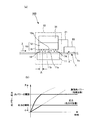
図1は、心線対照装置および方法の一実施形態を説明する概略図であり、図1(a)にその構成を示し、図1(b)にそれによる漏洩光パワーと応力の関係を示す。なお、図1中にてλは光ファイバ中を導通する光波を示し、λ’は光ファイバから漏れ出た漏洩光を示す。
[First embodiment]
A first embodiment of the cord contrast device and method according to the present invention will be described with reference to FIGS. In this embodiment, a case where the present invention is applied to an optical fiber with improved bending loss characteristics will be described.
FIG. 1 is a schematic diagram for explaining one embodiment of a cord contrast device and method. FIG. 1 (a) shows the configuration, and FIG. 1 (b) shows the relationship between leakage light power and stress. . In FIG. 1, λ indicates a light wave that is conducted through the optical fiber, and λ ′ indicates leaked light that has leaked from the optical fiber.
本実施形態に係る心線対照装置100は、図1(a)に示されるように、光ファイバ1上に周期的な応力を付加する応力付加器(応力付加手段)10および漏洩光λ’を受光する光検出器20から構成される。光検出器20は光ファイバ1から漏洩する漏洩光を検出する検出器である。
As shown in FIG. 1A, the core
応力付加器10は光ファイバ1に沿って周期的に応力を付加するための凹凸部分からなる突起部13を有し、応力を手動または電動で光ファイバ1に付加する機器である。すなわち、応力付加器10は光ファイバ1に対して所定の周期で応力を付与する機器であり、これにより長周期グレーティングを生成している。
The
応力付加器10は、光ファイバ設置台11、応力付与具15などを具備する。光ファイバ設置台11は光ファイバ1を設置する台である。光ファイバ設置台11の上部11aには光ファイバ1を設置するためのV溝11bが形成されている。応力付与具15は、光ファイバ設置台11に対して可動に設けられた可動具12と、この可動具12の下面12aに取付けられた複数の突起部13とを有するものである。応力付加器10は、さらに固定具14を具備する機器である。固定具14は、光ファイバ設置台11のV溝11b上に設置される光ファイバ1を光ファイバ設置台11に固定するものである。複数の突起部13は、周期的に配置されている。そして、応力付加器10の可動具12には、突起部13による応力を制御する応力制御装置31が取付けられている。これにより、光ファイバ1に入力された試験光(光波)λは、応力付加器10では周期および光ファイバ1の構造に対応した波長において高次モードが発生し、漏洩する。そして、この漏洩光λ'は、光ファイバ1の側面1cに接触して配置される光検出器20で検出される。これにより、光ファイバ1に光波λが導通していることを確認できる。すなわち、所望の光ファイバを特定することができる。
The
ここで導通と判定する光パワーをある閾値(所定の閾値)に予め設定する。そして、受光パワーが閾値を超えているか否かの結果を、制御信号線21を介して応力付加器10の応力制御装置31へフィードバックして応力付加器10の突起部13による応力の大きさを制御する。具体的には、図1(b)に示すように、応力制御装置31は、光検出器20で検出された光パワーが前記の閾値を超えた場合に応力付加器10を固定等することによって、応力付加器10において必要以上の応力が付加されないように制御する。このとき応力付加器10では光ファイバ1に過剰な応力が付加されないため、光ファイバ1への損傷を抑制することができ好ましい。
Here, the optical power determined to be conductive is set in advance to a certain threshold value (predetermined threshold value). Then, the result of whether or not the received light power exceeds the threshold value is fed back to the
ここで、図2に、本実施形態に係る心線対照装置および方法に関わる、応力付加器10による応力の大きさと光検出器20で検出される漏洩光λ’の光パワーの大きさとの関係を表す特性図を示す。ここで光ファイバとして空孔アシストファイバを用い、コア直径、比屈折率差、空孔位置(コアの中心から空孔の外形までの距離)、空孔直径および空孔の数量をそれぞれ9μm、0.35%、9μm、9μm、6個とした。この光ファイバの曲げ損失は半径5mmの急峻な曲げでも0.01dB/巻と非常に曲げ損失が小さいため、従来の心線対照方法を適用することができない。図2に示すように、応力付加を行うことによって、このような曲げ損失特性に優れた光ファイバにおいても、漏洩光を検出することができることを確認できる。また応力が大きくなるほど漏洩光パワーは大きくなり、たとえば−55dBmを前記の閾値とすると光ファイバに加わる応力を1500g重以下に抑えることができる。
Here, in FIG. 2, the relationship between the magnitude of the stress by the
したがって、本実施形態に係る心線対照装置100によれば、応力付加器10により光ファイバ1に応力を付加して光ファイバ1から光波λ'が漏洩して、この光波λ'を光検出器20で検出できる。また、応力制御装置31が光検出器20で検出される光パワーを持って応力付加器10を制御することで、光ファイバ1の損傷を回避できる。よって、光ファイバ1の曲げ損失特性に関わらず光ファイバ1を損傷させずに当該光ファイバ1から漏洩する光を検出して、所望の光ファイバの特定が可能となる。
Therefore, according to the core
心線対照装置100が固定具14を具備することにより、この固定具14により光ファイバ1を光ファイバ設置台11に固定でき、応力付加器10による光ファイバ1への応力付加を円滑に行うことができ、作業効率が向上する。
Since the optical
[第二の実施形態]
本発明に係る心線対照装置および方法の第二の実施形態につき図3を参照して説明する。
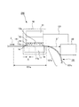
図3は本発明の心線対照装置および方法の構成例を示す概略図である。
本実施形態に係る心線対照装置は、図1(a)の構成の心線対照装置100を曲がって延在する光ファイバ101に適用した場合を示した装置である。なお、図3中にてλは光ファイバ中を導通する光波を示し、λ’は光ファイバから漏れ出た漏洩光を示す。
[Second Embodiment]
A second embodiment of the cord contrast device and method according to the present invention will be described with reference to FIG.
FIG. 3 is a schematic diagram showing an example of the configuration of the core wire contrast device and method of the present invention.
The core wire contrast device according to the present embodiment is a device that shows a case where the fiber
本実施形態に係る心線対照装置200は、上述した第一の実施形態に係る心線対照装置100と同一構成の機器(光ファイバ設置台11、応力付与具15(可動具12、突起部13)および固定具14からなる応力付加器10、応力制御装置31、光検出器20)を有する装置である。本実施形態では、上述した第一の実施形態に係る心線対照装置と同一の機器には同一符号を付記しその説明を省略する。すなわち、光ファイバ101は、直線状に延在する直線部101aと、この直線部101aに接続し、曲がって延在する曲げ部101bとを有する。この光ファイバの直線部101aに応力付加器10が配置される。そして、光ファイバ101の曲げ部101bに光検出器120が配置される。具体的には、光ファイバ101の直線部101aの延長線上に光検出器120が配置される。
The core
上述した形状の光ファイバ101であることにより、応力付加器10で発生する高次モードは伝搬モードに比べて曲げ損失が大きくなるため、曲げ部101bを形成し曲げ部101b近傍に光検出器120を設置することによって、より効率的に漏洩光λ’を検出することができる。また従来の単一モードファイバは比較的曲げ損失が大きいため、前記曲げ部101bにおいて伝搬モードに対する曲げ損失を発生する。試験光波長を固定してグレーティングを用いて漏洩光を発生させる場合、対象の光ファイバ構造に対してグレーティング周期を適切に設計する必要があるが、従来の単一モードファイバに対してはこの曲げ損失を検出することによって心線対照を行うことができる。すなわち従来の単一モードファイバに適した応力付加器の周期設計が不要であり、たとえば曲げ損失特性に優れた光ファイバように設計した本発明の心線対照装置および方法を用いて従来の単一モードファイバの対照を行え、好ましい。
Because of the
ここで、図3では光ファイバ101の曲げ部101bとして90度の曲げを仮定しているが、曲げ部は任意の角度の曲げであっても良く、また曲げの形は1回曲げの他に波型の曲げなど任意の形であってもかまわない。
Here, in FIG. 3, it is assumed that the bending
したがって、本実施形態に係る心線対照装置200によれば、上述した第一の実施形態に係る心線対照装置100と同様な作用効果を奏する上に、応力付加器10が光ファイバ101の光波λの進行方向における曲げ部101bよりも上流側に配置されることにより、応力付加器10による光ファイバ1への応力付加を円滑に行うことができる。光検出器20が光ファイバ101の曲げ部101bに配置されることにより、光ファイバ101から漏洩する光波λ'をより確実に光検出器20で検出できる。よって、作業効率が向上する。
Therefore, according to the core
本発明に係る心線対照装置および方法の第1の実施例につき、図4および図5を参照して説明する。
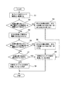
図4は本発明に係る心線対照装置および方法の第1の実施例の手順を示すフローチャートであり、図5は本発明に係る心線対照装置および方法の第1の実施例の構成を模式的に示す構成図である。なお、図5中にてλは光ファイバ中を導通する光波を示し、λ’は光ファイバから漏れ出た漏洩光を示す。
A first embodiment of the core wire contrast device and method according to the present invention will be described with reference to FIGS. 4 and 5. FIG.
FIG. 4 is a flowchart showing the procedure of the first embodiment of the cord contrast device and method according to the present invention, and FIG. 5 schematically shows the configuration of the first embodiment of the cord contrast device and method according to the present invention. FIG. In FIG. 5, λ indicates a light wave that is conducted through the optical fiber, and λ ′ indicates leaked light that has leaked from the optical fiber.
本実施例に係る心線対照装置300は、図5に示すように、応力付加器10、応力検出器20等を具備する。応力付加器10は、光ファイバ設置台11、応力付与具15(可動具12、突起部13)、および応力制御装置31を具備する。応力制御装置31は、信号線22を介して閾値判定器32と接続する。この閾値判定器32は、制御信号線21を介して光検出器20と接続する。この光検出器20は、光ファイバ1の側面1cに接触して配置される。閾値判定器32は、信号線23を介して閾値判定結果表示・発音器42と接続する。光検出器20は、信号線24を介して受光パワー表示器41と接続する。
As shown in FIG. 5, the core
光検出器20は、上述した通り光ファイバ1から漏洩する漏洩光を検出する検出器であり、光ファイバ1に対して曲げを与えることでより効率的な受光ができる。閾値判定器32は光検出器20において検出された光パワーが、予め設定した閾値を超えているか否かを判定する判定器である。突起部13は図1と同様に光ファイバ1に沿って周期的に応力を付加する。応力制御器31は応力付与具15への応力の大きさを制御する部分であり、閾値判定器32の結果をもって制御される。たとえば光検出器20での受光パワーが閾値判定器32において閾値を超えたと判定された場合、応力制御器31は応力付与具15を固定等することによって、光ファイバ1に対して判定時点より大きな応力がかからないように制御する。受光パワー表示器41は光検出器20において検出された光パワーを表示する。閾値判定結果表示・発音器42は閾値判定器32における判定結果を画面上の表示または音声によって結果を知らせる。
The
本実施例に係る心線対照方法は、図4に示すように、最初に光ファイバ設置台11に光ファイバ1を設置する(ステップS1)。このとき心線対照装置300に図3に示した光ファイバ101の曲げ部101bがあった場合に、光検出器20が検出する曲げ損失による漏洩光パワーが予め設定した閾値を超えているか否かを判定し(ステップS2)、超えていた場合に応力付加具13の固定等によって応力の付加を遮断し(ステップS3)、当該光ファイバ1で光波λが導通していると判定する(ステップS8)。曲げ部がない場合または曲げ部を有しているが閾値を超えていない場合に、手動または電動で応力付加器10により光フィアバ1に応力を付与する(ステップS4)。光検出器20において検出される光パワーが前記の閾値を超えた場合に、応力付与具15の固定等によって応力の制御を行い(ステップS6)、当該光ファイバ1に光波λが導通していると判定する(ステップS8)。また前記の閾値を越えていなくても光検出器20で光波λ’が検出されれば(ステップS7)、当該光ファイバ1に光波λが導通していると判定できる(ステップS8)。光検出器20において光波λ’が検出されない場合に、当該光ファイバには光波λが導通していないと判定する(ステップS9)。
In the core wire contrast method according to the present embodiment, the
したがって、本実施例に係る心線対照装置300によれば、応力付加器10により光ファイバ1に応力を付加して光ファイバ1から光波λ'が漏洩し、この光波λ'を光検出器20で検出できる。また、応力制御装置31が光検出器20で検出される光パワーを持って応力付加器10を制御することで、光ファイバ1の損傷を回避できる。よって、光ファイバ1の曲げ損失特性に関わらず光ファイバ1を損傷させずに当該光ファイバ1から漏洩する光を検出して、所望の光ファイバの特定が可能となる。
Therefore, according to the core
本発明に係る心線対照装置および方法の第2の実施例につき、図6および図7を参照して説明する。
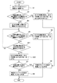
図6は本発明に係る心線対照装置および方法の第2の実施例の手順を示すフローチャートであり、図7は本発明に係る心線対照装置および方法の第2の実施例の構成を模式的に示す構成図である。なお、図7中にてλは光ファイバ中を導通する光波を示し、λ’は光ファイバから漏れ出た漏洩光を示す。
A second embodiment of the cord contrast device and method according to the present invention will be described with reference to FIGS.
FIG. 6 is a flowchart showing the procedure of the second embodiment of the cord contrast device and method according to the present invention, and FIG. 7 schematically shows the configuration of the second embodiment of the cord contrast device and method according to the present invention. FIG. In FIG. 7, λ represents a light wave that is conducted through the optical fiber, and λ ′ represents leaked light that has leaked from the optical fiber.
本実施例に係る心線対照装置は、上述した第1の実施例に係る心線対照装置と同一の機器構成(光ファイバ設置台11、応力付与具15(可動具12、突起部13)および固定具14からなる応力付加器10、光検出器20、制御信号線21、信号線22,23,24、応力制御装置31、応力判定器32、受光パワー表示器41、閾値判定結果表示・判定器42)に加え、応力検出器を具備する装置である。本実施例では、上述した第1の実施例に係る心線対照装置と同一の機器には同一符号を付記しその説明を省略する。
The core wire contrast device according to the present embodiment has the same equipment configuration as the above-described core wire contrast device according to the first embodiment (optical
本実施例に係る心線対照装置400は、図7に示すように、応力検出器401を具備する。この応力検出器401は可動具12と突起部13との間に配置される。そして、応力検出器401に信号線25が接続されている。この応力検出器401にて検出した突起部13による光ファイバ1への応力の大きさは信号線25を介して応力制御装置31へ出力されている。なお、ここでは、応力検出器401として可動具12と突起部13との間に配置される検出器を用いて説明したが、光ファイバ設置台11上に設けられた応力検出器とすることも可能である。
The core
そして、本実施例に係る心線対照方法は、図6に示すように、ステップS5による光検出器20で検出される光パワーが所定の閾値以上であるかの判定の後にステップS21およびステップ22の手順を追加したものである。
As shown in FIG. 6, in the method for contrasting cores according to the present embodiment, steps S21 and 22 are performed after determining whether the optical power detected by the
すなわち、ステップS5にて、光検出器20の光パワー、または高次モードによる漏洩光は閾値より小さいと判定されると、ステップS21に進む。このステップS21にて、応力付加器10による応力、または付与された応力が所定の閾値以上であるか判定される。所定の閾値を下回った場合にはステップS5に戻り、所定の閾値以上である場合にはステップS22に進む。ステップS22にて、応力付加器10を固定し、応力付加器10による応力を一定とする。そして、ステップS7に進み、上述した第1の実施例に係る心線対照方法と同様に、光検出器20で光波λ’の検出の有無が判定される。このステップS7にて光検出器20で光波λ’を検出した場合にはステップS8に進み、このステップS8で当該光ファイバ1に光波λが導通していると判定し、終了となる。他方、ステップS7にて光検出器20で光波λ’を検出していない場合にはステップS9に進み、このステップS9で当該光ファイバ1に光波λが導通していないと判定し、終了となる。
That is, if it is determined in step S5 that the optical power of the
したがって、本実施例に係る心線対照装置400によれば、光ファイバ1に応力付加器10により所定の周期で応力を付加し、光ファイバ1から漏れ出た光波λ’を光検出器20で検出して所望の光ファイバを特定する心線対照方法であって、光検出器20で光波λ’の光パワーを検出し、この光波λ’の光パワーが所定の閾値以上である場合には、応力付加器10により光ファイバ1へ付加する応力を一定に維持し、この光ファイバ1が所望の光ファイバであると判定することにより、光ファイバ1の損傷を回避できる上に、光ファイバ1の曲げ損失特性に関わらず光ファイバを損傷させずに当該光ファイバから漏洩する光λ’を光検出器20で検出して、所望の光ファイバの特定が可能となる。
Therefore, according to the core
光検出器20で検出された光波λ’の光パワーが所定の閾値未満であり、応力付加器10により光ファイバ1へ付加される応力を応力検出器401で検出し、この応力検出器401で検出された応力が所定の閾値未満である場合には、光検出器20で光波λ’の光パワーの判定を再度行うことにより、光ファイバ1に付与する応力を所定の閾値以下とすることができ、光ファイバ1の損傷をより確実に回避できる。また、応力付加器10による光ファイバ1への応力の付加を確実に行うことができ、所望の光ファイバを特定する作業をより確実に行うことができる。
The optical power of the light wave λ ′ detected by the
光検出器20で検出された光波λ’の光パワーが所定の閾値未満であり、応力検出器401で検出される応力が所定の閾値以上である場合に応力付加器10により光ファイバ1へ付加する応力を一定に維持した状態にて光検出器20で光波λ’の検出の有無を判定し、光検出器20で光波λ’を検出した場合には当該光ファイバ1が所望の光ファイバであると判定し、光検出器20で光波λ’を検出しない場合には当該光ファイバが所望の光ファイバではない判定することにより、所望の光ファイバを特定する作業をより一層確実に行うことができ、作業効率が向上する。
When the optical power of the light wave λ ′ detected by the
なお、上述の実施例では突起部13を長手方向に一定の周期を有する構造として説明したが、突起部での周期は長手方向に変動していてもよい。特に突起部の周期が長手方向に変化している場合は、所定の波長に対応できる光ファイバの構造の範囲が広がり、1つの構造での適用範囲が広がるため好ましい。同様に一定の周期の構造に対して光ファイバを曲げた状態で設置しても同様の結果が得られる。
In the above-described embodiment, the
本発明は、光線路の工事、保守、運用の際の、光ファイバの特定に利用することができる。 The present invention can be used for specifying an optical fiber during construction, maintenance, and operation of an optical line.
1,101 光ファイバ
10 応力付加器
20 光検出器
31 応力制御部装置
32 閾値判定器
41 受光パワー表示器
42 閾値判定結果表示・発音器
100,200,300,400 心線対照装置
201 応力検出器
λ 光波
DESCRIPTION OF SYMBOLS 1,101
Claims (2)
前記応力付加器は、該応力付加器により前記光ファイバに付加された応力を検出する応力検出器を具備するものであり、
前記光検出器で光波の光パワーを検出し、当該光波の光パワーが所定の閾値以上である場合には、前記応力付加器により光ファイバへ付加する応力を一定に維持し、当該光ファイバが所望の光ファイバであると判定し、
前記光検出器で検出された光波の光パワーが所定の閾値未満であり、前記応力検出器で検出された応力が所定の閾値未満である場合には、前記光検出器で光波の光パワーの判定を再度行い、
前記光検出器で検出された光波の光パワーが所定の閾値未満であり、前記応力検出器で検出された応力が所定の閾値以上である場合に、前記応力付加器により前記光ファイバへ付加する応力を一定に維持した状態にて前記光検出器で光波の検出の有無を判定し、前記光検出器で光波を検出した場合には当該光ファイバが所望の光ファイバであると判定し、前記光検出器で光波を検出しない場合には当該光ファイバが所望の光ファイバではないと判定する
ことを特徴とする心線対照方法。 Against the optical fiber, along the longitudinal direction of the optical fiber by adding a stress in a predetermined spatial periodicity by stressing device, an optical wave leaked from the optical fiber while increasing the the stress with time at the photodetector A cord contrast method for detecting and identifying a desired optical fiber, comprising:
The stress adder comprises a stress detector that detects the stress applied to the optical fiber by the stress adder,
When the optical power of the optical wave is detected by the optical detector and the optical power of the optical wave is equal to or greater than a predetermined threshold, the stress applied to the optical fiber by the stress adder is maintained constant, and the optical fiber is Determine that it is the desired optical fiber,
When the optical power of the light wave detected by the photodetector is less than a predetermined threshold value, and the stress detected by the stress detector is less than a predetermined threshold value, the optical power of the light wave is detected by the photodetector. Make a decision again,
When the optical power of the light wave detected by the photodetector is less than a predetermined threshold and the stress detected by the stress detector is greater than or equal to a predetermined threshold, the stress is added to the optical fiber by the stress adder. In the state where the stress is kept constant, it is determined whether or not a light wave is detected by the light detector, and when the light wave is detected by the light detector, it is determined that the optical fiber is a desired optical fiber, A method of contrasting cores, wherein when a light wave is not detected by a photodetector, it is determined that the optical fiber is not a desired optical fiber.
前記光ファイバは曲がって延在する曲げ部を有し、
前記応力付加器は、前記光ファイバの光波の進行方向における前記曲げ部よりも上流側に配置され、
前記光検出器は、前記光ファイバの前記曲げ部に配置される
ことを特徴とする心線対照方法。 The method of controlling a core wire according to claim 1,
The optical fiber has a bent portion extending in a bending manner;
The stress adder is disposed upstream of the bent portion in the traveling direction of the light wave of the optical fiber,
2. The method according to claim 1, wherein the photodetector is disposed in the bent portion of the optical fiber.
Priority Applications (1)
| Application Number | Priority Date | Filing Date | Title |
|---|---|---|---|
| JP2008031753A JP5363003B2 (en) | 2008-02-13 | 2008-02-13 | Core wire contrast method |
Applications Claiming Priority (1)
| Application Number | Priority Date | Filing Date | Title |
|---|---|---|---|
| JP2008031753A JP5363003B2 (en) | 2008-02-13 | 2008-02-13 | Core wire contrast method |
Publications (2)
| Publication Number | Publication Date |
|---|---|
| JP2009192300A JP2009192300A (en) | 2009-08-27 |
| JP5363003B2 true JP5363003B2 (en) | 2013-12-11 |
Family
ID=41074459
Family Applications (1)
| Application Number | Title | Priority Date | Filing Date |
|---|---|---|---|
| JP2008031753A Expired - Fee Related JP5363003B2 (en) | 2008-02-13 | 2008-02-13 | Core wire contrast method |
Country Status (1)
| Country | Link |
|---|---|
| JP (1) | JP5363003B2 (en) |
Families Citing this family (1)
| Publication number | Priority date | Publication date | Assignee | Title |
|---|---|---|---|---|
| JP2016208256A (en) * | 2015-04-22 | 2016-12-08 | 西日本電信電話株式会社 | Optical power monitoring device and optical communication network system |
Family Cites Families (4)
| Publication number | Priority date | Publication date | Assignee | Title |
|---|---|---|---|---|
| GB2182516A (en) * | 1985-11-01 | 1987-05-13 | Stc Plc | Optical fibre network |
| JPS63305304A (en) * | 1987-06-08 | 1988-12-13 | Nippon Telegr & Teleph Corp <Ntt> | Method for fiber identification of optical fiber communication line |
| JP4781906B2 (en) * | 2006-05-19 | 2011-09-28 | 日本電信電話株式会社 | Optical fiber core contrast method and optical fiber core contrast device using the same |
| JP5384812B2 (en) * | 2007-09-07 | 2014-01-08 | 日本電信電話株式会社 | Cord control method and apparatus using long period grating |
-
2008
- 2008-02-13 JP JP2008031753A patent/JP5363003B2/en not_active Expired - Fee Related
Also Published As
| Publication number | Publication date |
|---|---|
| JP2009192300A (en) | 2009-08-27 |
Similar Documents
| Publication | Publication Date | Title |
|---|---|---|
| RU2444770C2 (en) | Fibre fusion delimitre, fibre laser and optical transmission line | |
| WO2019172276A1 (en) | Optical fiber monitoring method, and optical fiber monitoring system | |
| JP5313079B2 (en) | Optical fiber characterization method | |
| JP2013113890A (en) | Optical fiber coupling device and optical fiber coupling method | |
| JP5469816B2 (en) | Core wire contrast method and device | |
| JP2009025210A (en) | Optical fiber side incidence method and apparatus | |
| JP5363003B2 (en) | Core wire contrast method | |
| JPWO2010021207A1 (en) | Core wire contrast device and method | |
| CN103168262A (en) | Optical transmission line | |
| JP5264336B2 (en) | Flood detection module and flood detection method using the same | |
| JP5384812B2 (en) | Cord control method and apparatus using long period grating | |
| US20130343704A1 (en) | Compact mode-size transition using a focusing reflector | |
| JP4781906B2 (en) | Optical fiber core contrast method and optical fiber core contrast device using the same | |
| JP5365338B2 (en) | Cut-off wavelength measuring method and optical communication system | |
| KR101621478B1 (en) | Tracking System for Cable Line | |
| JP4702846B2 (en) | Connection loss judgment method at optical fiber connection point | |
| JP2010032238A (en) | Core wire comparison method and apparatus | |
| KR101090882B1 (en) | Microbend producer of optical fiber and method of measuring the cable's curvature using fiber optic microbending | |
| JP5524655B2 (en) | Local signal optical fiber coupling method and local signal optical fiber coupling device | |
| JP2009300317A (en) | Method and device for estimating connection loss of optical fiber | |
| JP4822868B2 (en) | Optical fiber status judgment method | |
| JP4548841B2 (en) | Optical fiber splice loss judgment method | |
| JP2005337804A (en) | Fault location support method in optical fiber | |
| JP5032950B2 (en) | Inundation detection device and inundation detection method | |
| JP2009294100A (en) | Fiber identification method and device using short-wavelength region |
Legal Events
| Date | Code | Title | Description |
|---|---|---|---|
| A621 | Written request for application examination |
Free format text: JAPANESE INTERMEDIATE CODE: A621 Effective date: 20100115 |
|
| A977 | Report on retrieval |
Free format text: JAPANESE INTERMEDIATE CODE: A971007 Effective date: 20120210 |
|
| A131 | Notification of reasons for refusal |
Free format text: JAPANESE INTERMEDIATE CODE: A131 Effective date: 20120327 |
|
| A521 | Written amendment |
Free format text: JAPANESE INTERMEDIATE CODE: A523 Effective date: 20120528 |
|
| A131 | Notification of reasons for refusal |
Free format text: JAPANESE INTERMEDIATE CODE: A131 Effective date: 20121127 |
|
| A521 | Written amendment |
Free format text: JAPANESE INTERMEDIATE CODE: A523 Effective date: 20130125 |
|
| RD01 | Notification of change of attorney |
Free format text: JAPANESE INTERMEDIATE CODE: A7426 Effective date: 20130314 |
|
| TRDD | Decision of grant or rejection written | ||
| A01 | Written decision to grant a patent or to grant a registration (utility model) |
Free format text: JAPANESE INTERMEDIATE CODE: A01 Effective date: 20130903 |
|
| A61 | First payment of annual fees (during grant procedure) |
Free format text: JAPANESE INTERMEDIATE CODE: A61 Effective date: 20130905 |
|
| R150 | Certificate of patent or registration of utility model |
Ref document number: 5363003 Country of ref document: JP Free format text: JAPANESE INTERMEDIATE CODE: R150 Free format text: JAPANESE INTERMEDIATE CODE: R150 |
|
| S531 | Written request for registration of change of domicile |
Free format text: JAPANESE INTERMEDIATE CODE: R313531 |
|
| R350 | Written notification of registration of transfer |
Free format text: JAPANESE INTERMEDIATE CODE: R350 |
|
| LAPS | Cancellation because of no payment of annual fees |