JP5356503B2 - Method and apparatus for linking a modulation and coding scheme to a quantity of resources - Google Patents
Method and apparatus for linking a modulation and coding scheme to a quantity of resources Download PDFInfo
- Publication number
- JP5356503B2 JP5356503B2 JP2011506798A JP2011506798A JP5356503B2 JP 5356503 B2 JP5356503 B2 JP 5356503B2 JP 2011506798 A JP2011506798 A JP 2011506798A JP 2011506798 A JP2011506798 A JP 2011506798A JP 5356503 B2 JP5356503 B2 JP 5356503B2
- Authority
- JP
- Japan
- Prior art keywords
- control
- input parameters
- offset
- bits
- signaling
- Prior art date
- Legal status (The legal status is an assumption and is not a legal conclusion. Google has not performed a legal analysis and makes no representation as to the accuracy of the status listed.)
- Active
Links
Images


Classifications
-
- H—ELECTRICITY
- H04—ELECTRIC COMMUNICATION TECHNIQUE
- H04L—TRANSMISSION OF DIGITAL INFORMATION, e.g. TELEGRAPHIC COMMUNICATION
- H04L5/00—Arrangements affording multiple use of the transmission path
- H04L5/003—Arrangements for allocating sub-channels of the transmission path
- H04L5/0053—Allocation of signaling, i.e. of overhead other than pilot signals
-
- H—ELECTRICITY
- H04—ELECTRIC COMMUNICATION TECHNIQUE
- H04L—TRANSMISSION OF DIGITAL INFORMATION, e.g. TELEGRAPHIC COMMUNICATION
- H04L1/00—Arrangements for detecting or preventing errors in the information received
- H04L1/0001—Systems modifying transmission characteristics according to link quality, e.g. power backoff
- H04L1/0023—Systems modifying transmission characteristics according to link quality, e.g. power backoff characterised by the signalling
- H04L1/0026—Transmission of channel quality indication
-
- H—ELECTRICITY
- H04—ELECTRIC COMMUNICATION TECHNIQUE
- H04L—TRANSMISSION OF DIGITAL INFORMATION, e.g. TELEGRAPHIC COMMUNICATION
- H04L1/00—Arrangements for detecting or preventing errors in the information received
- H04L1/0001—Systems modifying transmission characteristics according to link quality, e.g. power backoff
- H04L1/0023—Systems modifying transmission characteristics according to link quality, e.g. power backoff characterised by the signalling
- H04L1/0028—Formatting
- H04L1/0029—Reduction of the amount of signalling, e.g. retention of useful signalling or differential signalling
-
- H—ELECTRICITY
- H04—ELECTRIC COMMUNICATION TECHNIQUE
- H04L—TRANSMISSION OF DIGITAL INFORMATION, e.g. TELEGRAPHIC COMMUNICATION
- H04L1/00—Arrangements for detecting or preventing errors in the information received
- H04L1/12—Arrangements for detecting or preventing errors in the information received by using return channel
- H04L1/16—Arrangements for detecting or preventing errors in the information received by using return channel in which the return channel carries supervisory signals, e.g. repetition request signals
- H04L1/18—Automatic repetition systems, e.g. Van Duuren systems
- H04L1/1825—Adaptation of specific ARQ protocol parameters according to transmission conditions
-
- H—ELECTRICITY
- H04—ELECTRIC COMMUNICATION TECHNIQUE
- H04L—TRANSMISSION OF DIGITAL INFORMATION, e.g. TELEGRAPHIC COMMUNICATION
- H04L1/00—Arrangements for detecting or preventing errors in the information received
- H04L1/12—Arrangements for detecting or preventing errors in the information received by using return channel
- H04L1/16—Arrangements for detecting or preventing errors in the information received by using return channel in which the return channel carries supervisory signals, e.g. repetition request signals
- H04L1/18—Automatic repetition systems, e.g. Van Duuren systems
- H04L1/1829—Arrangements specially adapted for the receiver end
- H04L1/1861—Physical mapping arrangements
-
- H—ELECTRICITY
- H04—ELECTRIC COMMUNICATION TECHNIQUE
- H04L—TRANSMISSION OF DIGITAL INFORMATION, e.g. TELEGRAPHIC COMMUNICATION
- H04L5/00—Arrangements affording multiple use of the transmission path
- H04L5/003—Arrangements for allocating sub-channels of the transmission path
Description
本発明は、ワイヤレステレコミュニケーションの分野に係る。より詳細には、本発明は、ワイヤレステレコミュニケーションにおけるリソース割り当てに関する。 The present invention relates to the field of wireless telecommunications. More particularly, the present invention relates to resource allocation in wireless telecommunications.
関連出願の相互参照:本願は、2008年4月28日に出願された米国仮特許出願第61/125,961号の優先権を主張する。又、本願は、2008年4月29日に出願された米国仮特許出願第61/048,554号及び第61/048,908号の優先権も主張する。 Cross-reference to related applications: This application claims priority to US Provisional Patent Application No. 61 / 125,961, filed April 28, 2008. This application also claims the priority of US Provisional Patent Applications Nos. 61 / 048,554 and 61 / 048,908 filed on April 29, 2008.
テレコミュニケーション産業は、ブロードバンドサービスをサポートしながら高速アクセスも含む融通性のある手頃な新世代の通信を開発中である。第3世代(3G)移動テレコミュニケーションシステムの多くの特徴が既に確立されているが、他の多くの特徴は、まだ完全ではない。これらの開発においては第3世代パートナーシッププロジェクト(3GPP)が中枢である。 The telecommunications industry is developing a flexible and affordable new generation of communications, including high-speed access while supporting broadband services. Many features of third generation (3G) mobile telecommunications systems have already been established, but many other features are not yet complete. The third generation partnership project (3GPP) is at the heart of these developments.
第3世代の移動テレコミュニケーション内に入るシステムの1つは、固定及び移動顧客に音声、データ、マルチメディア及びワイドバンド情報を配信するユニバーサル移動テレコミュニケーションシステム(UMTS)である。このUMTSは、大きなシステム容量及びデータ容量を収容するように設計される。UMTSでは、電磁スペクトルを効率的に使用することが重要である。スペクトル効率は、周波数分割デュープレックス(FDD)スキームを使用して又は時分割デュープレックス(TDD)スキームを使用して達成できることが知られている。スペース分割デュープレックス(SDD)は、ワイヤレステレコミュニケーションに使用される第3のデュープレックス送信方法である。 One system that falls within the third generation of mobile telecommunications is the Universal Mobile Telecommunication System (UMTS) that delivers voice, data, multimedia and wideband information to fixed and mobile customers. This UMTS is designed to accommodate large system capacity and data capacity. In UMTS, it is important to use the electromagnetic spectrum efficiently. It is known that spectral efficiency can be achieved using a frequency division duplex (FDD) scheme or using a time division duplex (TDD) scheme. Space division duplex (SDD) is a third duplex transmission method used for wireless telecommunications.
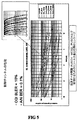
図1に見られるように、UMTSアーキテクチャーは、ユーザ装置102(UE)、UMTS地上無線アクセスネットワーク104(UTRAN)及びコアネットワーク126(CN)より成る。UTRANとUEとの間のエアインターフェイスは、Uuと称され、UTRANとコアネットワークとの間のインターフェイスは、Iuと称される。 As seen in FIG. 1, the UMTS architecture consists of a user equipment 102 (UE), a UMTS terrestrial radio access network 104 (UTRAN), and a core network 126 (CN). The air interface between the UTRAN and the UE is called Uu, and the interface between the UTRAN and the core network is called Iu.
高速ダウンリンクパケットアクセス(HSDPA)及び高速アップリンクパケットアクセス(HSUPA)は、高速パケットアクセス(HSPA)ファミリーにおける更に別の3G移動電話プロトコルである。それらは、高いデータ転送速度を許すUMTSベースのネットワークのための滑らかな進化路を与えるものである。 High speed downlink packet access (HSDPA) and high speed uplink packet access (HSUPA) are yet another 3G mobile telephone protocols in the high speed packet access (HSPA) family. They provide a smooth evolution path for UMTS-based networks that allow high data rates.
進化型UTRAN(EUTRAN)は、HSPAより最近のプロジェクトであり、3Gを更に未来へ繋げていくことを意味する。EUTRANは、種々の予想される要件に対処するために、UMTS移動電話規格を改善するよう設計される。EUTRANは、しばしば、長期的進化(LTE)によって指示され、システムアーキテクチャー進化(SAE)のような用語にも関連している。EUTRANの1つのターゲットは、全てのインターネットプロトコル(IP)システムがIPデータを効率的に送信できるようにすることである。このシステムは、音声及びデータコールに対してPS(パケット交換)ドメインしか使用せず、即ちシステムは、ボイスオーバーインターネットプロトコル(VoIP)を含む。 Evolved UTRAN (EUTRAN) is a more recent project than HSPA, meaning that 3G will be further connected to the future. EUTRAN is designed to improve the UMTS mobile phone standard to address various anticipated requirements. EUTRAN is often dictated by long-term evolution (LTE) and is also related to terms like system architecture evolution (SAE). One target of EUTRAN is to enable all Internet Protocol (IP) systems to transmit IP data efficiently. This system uses only the PS (packet switched) domain for voice and data calls, i.e. the system includes Voice over Internet Protocol (VoIP).
LTEに関する情報は、参考としてここにそのまま援用する3GPP TS 36.300(V8.0.0、2007年3月)、Evolved Universal Terrestrial Radio Access (E-UTRA) and Evolved Universal Terrestrial Radio Access Network (E-UTRA) Overall description; Stage 2 (Release 8)に見ることができる。UTRAN及びEUTRANは、以下に、ある程度詳細に説明するが、特に、E−UTRANが時間と共に進化していることを理解されたい。 For information on LTE, 3GPP TS 36.300 (V8.0.0, March 2007), Evolved Universal Terrestrial Radio Access (E-UTRA) and Evolved Universal Terrestrial Radio Access Network (E-E) UTRA) Overall description; can be seen in Stage 2 (Release 8). UTRAN and EUTRAN are described in some detail below, but in particular, it should be understood that E-UTRAN is evolving over time.
UTRANは、1組の無線ネットワークサブシステム128(RNS)より成り、その各々は、図1に見られるように、多数のセル110(C)の地理的カバレージを有する。サブシステム間のインターフェイスは、Iurと称される。各無線ネットワークサブシステム128(RNS)は、無線ネットワークコントローラ112(RNC)及び少なくとも1つのノードB114を備え、各ノードBは、少なくとも1つのセル110の地理的カバレージを有する。図1から明らかなように、RNC112とノードB114との間のインターフェイスは、Iubと称され、このIubは、エアインターフェイスではなくて、固定配線である。どのノードB114にも、1つのRNC112しかない。ノードB114は、UE102と無線送信及び受信を行う役割を果たす(ノードBのアンテナは、典型的に塔の頂上に見ることができるか、又は好ましくは見難い位置にある)。RNC112は、RNS128内の各ノード114の論理的リソースを完全に制御し、又、RNC112は、あるセルから別のセルへ又は同じセルの無線チャンネル間でコールを切り換えることを含むハンドオーバー判断を行う役割を果たす。
UTRAN consists of a set of radio network subsystems 128 (RNS), each of which has a geographic coverage of multiple cells 110 (C), as seen in FIG. The interface between subsystems is called Iur. Each radio network subsystem 128 (RNS) comprises a radio network controller 112 (RNC) and at least one
UMTS無線ネットワークにおいて、UEは、サービスクオリティの異なる複数のアプリケーションを同時に実行することをサポートできる。MACレイヤでは、複数の論理的チャンネルを単一のトランスポートチャンネルへマルチプレクスすることができる。トランスポートチャンネルは、論理的チャンネルからのトラフィックがどのように処理されて物理的レイヤへ送信されるか規定することができる。MACと物理的レイヤとの間で交換される基本的データユニットは、トランスポートブロック(TB)と称される。これは、RLC PDU及びMACヘッダより成る。送信時間インターバル(TTI)と称される期間中に、多数のトランスポートブロック及び幾つかの他のブロックが物理的レイヤへと配送される。 In a UMTS wireless network, a UE can support simultaneously executing multiple applications with different quality of service. At the MAC layer, multiple logical channels can be multiplexed into a single transport channel. A transport channel can define how traffic from a logical channel is processed and sent to the physical layer. The basic data unit exchanged between the MAC and the physical layer is called a transport block (TB). This consists of an RLC PDU and a MAC header. During a period referred to as a transmission time interval (TTI), a number of transport blocks and several other blocks are delivered to the physical layer.
一般的に述べると、大文字又は小文字の“E”のプレフィックスは、長期的進化(LTE)を意味する。E−UTRANは、UEに向いたE−UTRAユーザ平面(RLC/MAC/PHY)及び制御平面(RRC)プロトコルターミネーションを与えるeNB(E−UTRANノードB)より成る。eNBは、S1を経てアクセスゲートウェイ(aGW)へインターフェイスし、そしてX2を経て相互接続される。 Generally speaking, an uppercase or lowercase “E” prefix means long term evolution (LTE). E-UTRAN consists of an E-UTRA user plane (RLC / MAC / PHY) and control plane (RRC) protocol termination towards the UE (E-UTRAN Node B). The eNB interfaces to the access gateway (aGW) via S1 and is interconnected via X2.
E−UTRANアーキテクチャーの一例が、図2に示されている。E−UTRANのこの例は、UEに向いたE−UTRAユーザ平面(RLC/MAC/PHY)及び制御平面(RRC)プロトコルターミネーションを与えるeNBより成る。eNBは、S1インターフェイスによりEPC(進化型パケットコア)に接続され、これは、移動管理エンティティ(MME)及び/又はアクセスゲートウェイ(aGW)のようなゲートウェイで作られる。S1インターフェイスは、MMEとeNBとの間の多数・対・多数関係をサポートする。eNBには、パケットデータコンバージェンスプロトコル(PDCP)が配置される。 An example of an E-UTRAN architecture is shown in FIG. This example of E-UTRAN consists of an eNB that provides E-UTRA user plane (RLC / MAC / PHY) and control plane (RRC) protocol termination for the UE. The eNB is connected to the EPC (Evolved Packet Core) via the S1 interface, which is made with a gateway such as a mobility management entity (MME) and / or an access gateway (aGW). The S1 interface supports a many-to-many relationship between the MME and the eNB. A packet data convergence protocol (PDCP) is arranged in the eNB.
この例では、互いに通信する必要のあるeNB間にX2インターフェイスが存在する。例外的なケース(例えば、PLMN間ハンドオーバー)では、LTE_ACTIVEのeNB間移動がMMEリロケーションによりS1インターフェイスを経てサポートされる。 In this example, there is an X2 interface between eNBs that need to communicate with each other. In exceptional cases (eg, inter-PLMN handover), LTE_ACTIVE inter-eNB movement is supported via the S1 interface by MME relocation.
eNBは、無線リソース管理(無線ベアラ制御、無線アドミッション制御、接続移動制御、アップリンク及びダウンリンクの両方におけるUEへのリソースの動的な割り当て)、UEアタッチメントにおける移動管理エンティティ(MME)の選択、(MMEから発信される)ページングメッセージのスケジューリング及び送信、MME又はO&Mから発信されるブロードキャスト情報のスケジュールング及び送信、並びに移動及びスケジューリングのための測定及び測定報告構成のような機能をホストする。MMEは、次のような機能、即ちeNBへのページングメッセージの配布、セキュリティ制御、ユーザデータストリームのIPヘッダ圧縮及び暗号化、ページングの理由でのU平面パケットの終了、UE移動をサポートするためのU平面のスイッチング、アイドル状態移動制御、システムアーキテクチャー進化(SAE)ベアラ制御、並びにNASシグナリングの暗号化及び完全性保護をホストする。 eNB, radio resource management (radio bearer control, radio admission control, connection mobility control, dynamic allocation of resources to UE in both uplink and downlink), selection of mobility management entity (MME) in UE attachment Hosting functions such as scheduling and transmission of paging messages (originating from MME), scheduling and transmission of broadcast information originating from MME or O & M, and measurement and measurement reporting configuration for mobility and scheduling. MME supports the following functions: distribution of paging message to eNB, security control, IP header compression and encryption of user data stream, termination of U-plane packet for paging reason, UE movement It hosts U-plane switching, idle state mobility control, system architecture evolution (SAE) bearer control, and NAS signaling encryption and integrity protection.
TSG−RAN WG1#50、R1−073842、ギリシャ、アテネ、2007年8月20−24“Notes from uplink control signaling discussions”をそのままここに援用する。アテネで開催されたRAN1#50では、PUSCHの制御シグナリングに関連した多数の仮定が合意された。
・データ及び異なる制御フィールド(ACK/NACK、CQI/PMI)は、個別の変調記号へマップされる。ここで、ACKは、確認を意味し、NACKは、否定確認を意味し、CQIは、チャンネルクオリティインジケータを意味する。
・制御のための異なるコードレートが、異なる数の記号を占有することにより達成される。
・制御シグナリングに対して使用すべきコードレートがPUSCH MCSにより与えられる。その関係がテーブルに表される。
・テーブルは、各PUSCH MCSを、制御シグナリングのための所与のコードレート、即ちACK/NAK又はあるCQI/PMIサイズに対して使用すべき記号の数、にリンクさせる。
TSG-RAN WG1 # 50, R1-073842, Athens, Greece, August 24, 2007, “Notes from uplink control signaling discussions” is incorporated herein by reference in its entirety. At RAN1 # 50 held in Athens, a number of assumptions related to PUSCH control signaling were agreed.
Data and different control fields (ACK / NACK, CQI / PMI) are mapped to individual modulation symbols. Here, ACK means confirmation, NACK means negative confirmation, and CQI means channel quality indicator.
Different code rates for control are achieved by occupying different numbers of symbols.
The code rate to be used for control signaling is given by the PUSCH MCS. The relationship is represented in a table.
The table links each PUSCH MCS to a given code rate for control signaling, ie the number of symbols to use for ACK / NAK or some CQI / PMI size.
3GPP TSG RAN WG1、2008年3月31日から4月4日に中国シンセンで開催されたミーティング#52bis、R1−081165も、参考としてここに(そのまま)援用する。又、3GPP TSG RAN1#52−Bis、中国シンセン、2008年3月31日から4月4日:“Resource Provision for UL Control in PUSCH”も、参考としてここに(そのまま)援用する。RAN1#52bisでは、上述したマルチプレクシングが更に鋭敏にされた。
・PUSCHのCQI/PMIはPUSCHのデータと同じ変調スキームを使用する。
・データMCSと制御シグナリングのコードレートとの間の半静的構成のオフセットが適用される(A/N及びCQI)。
・次のステップ:オフセット値を定義する。例えば、サービスクオリティ(QoS)の異なる複数のサービスが時間マルチプレクスされるときに複数のオフセットが必要とされるかどうか検討する。
3GPP TSG RAN WG1, Meeting # 52bis, R1-081165 held in Shenzhen, China from March 31 to April 4, 2008, is incorporated herein by reference. Also, 3GPP TSG RAN1 # 52-Bis, China Shenzhen, March 31 to April 4, 2008: “Resource Provision for UL Control in PUSCH” is incorporated herein by reference (as is). In RAN1 # 52bis, the above-described multiplexing has been further enhanced.
-PUSCH CQI / PMI uses the same modulation scheme as PUSCH data.
A semi-static configuration offset between data MCS and control signaling code rate is applied (A / N and CQI).
Next step: Define the offset value. For example, consider whether multiple offsets are required when multiple services with different quality of service (QoS) are time multiplexed.
既存の技術は、PUSCH MSCと、PUSCH上で制御するためのリソースの量とをどのようにリンクするか、又はULデータとマルチプレクスされるときにアップリンク(UL)制御信号に対して充分なクオリティをどのように保証するか、に対処するものではない。制御信号に対してリソースを割り当てるときに考慮する必要のある問題が幾つかある。 Existing technology is sufficient for uplink (UL) control signals to link PUSCH MSCs and the amount of resources to control on PUSCH or when multiplexed with UL data. It does not address how to guarantee quality. There are several issues that need to be considered when allocating resources for control signals.
1.制御チャンネルクオリティ
・ACK/NACK及びCQIは、B(L)ER性能に関して厳密な要求がある。
・遅延要求のために制御信号で再送信を適用することはできない。
1. Control channel quality ACK / NACK and CQI have strict requirements on B (L) ER performance.
• Retransmission cannot be applied with a control signal due to a delay request.
2.データ優位性
・データクオリティは、MCS選択及びPUSCH電力制御のための動作点を定義する。
・制御チャンネルは、所与のSINR動作点に適応しなければならない。
・異なるチャンネルに対して正しいレートのマッチング/デマッチング及びエンコード/デコード動作を遂行するためには無線リンクの両端においてデータと制御との間の記号分割に関する情報を事前に知らねばならない。
2. Data superiority Data quality defines the operating point for MCS selection and PUSCH power control.
The control channel must adapt to a given SINR operating point.
In order to perform correct rate matching / dematching and encoding / decoding operations for different channels, information on symbol division between data and control must be known in advance at both ends of the radio link.
3.異なるB(L)ER動作点
・データチャンネルは、ハイブリッド自動リピート要求(HARQ)及びリンク適応(LA)を使用し、一方、制御シグナリングは、高速リンク適応からもHARQからも有益でない。
・チャンネルコード化。
・データチャンネルは、ターボコード及び非常に大きなコードブロックサイズを有する。
・制御チャンネルは、比較的小さなコードブロックサイズ及び小さなコード利得を有する(ACK/NACKは、繰り返しコードしかもたない)。
3. Different B (L) ER operating points The data channel uses hybrid auto-repeat request (HARQ) and link adaptation (LA), while control signaling is not beneficial from fast link adaptation or HARQ.
・ Channel coding.
The data channel has a turbo code and a very large code block size.
The control channel has a relatively small code block size and a small code gain (ACK / NACK has only repetitive codes).
上述した問題に対する詳細な解決策として利用できる従来技術は本質的にない。R1−081295は、データMCSレベルに基づいて制御領域のサイズを決定する式を提示する。しかしながら、R1−081295で提示された解決策には、多数の欠点がある。例えば、
・無用な項Kc(オフセットパラメータに結合する)
・無用な関数log2()(オフセットパラメータに結合する)
・データMCSと制御チャンネルのサイズとの間の「定義されない」関係
・R1−081295ではこの式の実現性を示すための性能結果が提示されない。
There is essentially no prior art that can be used as a detailed solution to the problems described above. R1-081295 presents an equation that determines the size of the control region based on the data MCS level. However, the solution presented in R1-081295 has a number of drawbacks. For example,
-Unnecessary term Kc (combined with offset parameter)
-Unnecessary function log 2 () (coupled to offset parameter)
“Undefined” relationship between data MCS and control channel size • R1-081295 does not present performance results to show the feasibility of this equation.
これらの欠点は、上述した問題を充分に解決すると共に、ULデータとマルチプレクスされるときにUL制御信号に対する充分なクオリティを保証するための解決策を必要とする。 These drawbacks require a solution to fully solve the above-mentioned problems and to ensure sufficient quality for UL control signals when multiplexed with UL data.
本発明は、E−UTRAN(LTE又は3.9G)の環境に適用することができる。しかしながら、その原理は、このような環境に限定されず、むしろ、他の種々の現在及び将来のワイヤレステレコミュニケーションシステム及びアクセス技術にも適用できる。 The present invention can be applied to an E-UTRAN (LTE or 3.9G) environment. However, the principles are not limited to such environments, but rather can be applied to various other current and future wireless telecommunications systems and access technologies.
本発明の実施形態は、例えば、Rel.8ワークアイテムのもとで3GPPに指定されたUTRAN長期的進化(LTE)のUL部分に係ると共に、PUSCH(物理的アップリンク共有チャンネル)のULデータと共に送信される非データ関連制御信号(ACK/NACK及びCQIのような)に対するリソース割り当てにも係る。データ非関連制御シグナリングは、時分割多重化(TDM)によりULデータとでマルチプレクスすることができる。 Embodiments of the present invention are described, for example, in Rel. A non-data related control signal (ACK /) associated with the UL part of UTRAN Long Term Evolution (LTE) specified in 3GPP under 8 work items and transmitted with the PUSCH (Physical Uplink Shared Channel) UL data. It also relates to resource allocation for (such as NACK and CQI). Data unrelated control signaling can be multiplexed with UL data by time division multiplexing (TDM).
本発明は、物理的アップリンク制御チャンネル(PUSCH)の変調及びコード化スキーム(MCS)と、PUSCH上で制御するためのリソースの量との間をリンクする方法及び装置を包含する。本発明のある実施形態によれば、制御領域のサイズの柔軟な適応を許して、制御チャンネルのクオリティを制御するように制御リソース(CQI&ACK/NACK)の量をスケーリングするためのメカニズム及び/又は式が提供される。これは、ターゲット要件を満足するためにUL制御シグナリングのクオリティを適応させることができるようにする。 The present invention encompasses a method and apparatus for linking between a physical uplink control channel (PUSCH) modulation and coding scheme (MCS) and the amount of resources to control on the PUSCH. According to an embodiment of the present invention, a mechanism and / or equation for scaling the amount of control resources (CQI & ACK / NACK) to control the quality of the control channel, allowing flexible adaptation of the size of the control region. Is provided. This allows the quality of UL control signaling to be adapted to meet target requirements.
本発明の好ましい実施形態を以下に説明する。これは、単に、本発明を実施する1つの仕方を例示するものに過ぎず、本発明の範囲をそれに限定するものではない。 Preferred embodiments of the present invention are described below. This is merely illustrative of one way of practicing the invention and is not intended to limit the scope of the invention thereto.
本発明のこの実施形態は、多数の予め定められた入力パラメータで制御信号領域のサイズを決定するための方法及び手順を提供する。本発明のこの実施形態は、これらパラメータを入力として利用するアルゴリズムを含む。目標は、この方法及び手順を標準化して、UE及びeNodeBの両方が利用できるようにすることである。 This embodiment of the invention provides a method and procedure for determining the size of the control signal region with a number of predetermined input parameters. This embodiment of the invention includes an algorithm that utilizes these parameters as inputs. The goal is to standardize this method and procedure so that it can be used by both the UE and the eNodeB.
この実施形態により網羅される別の主題は、eNBにおいてACK/NACKの改善されたDTX検出をサポートする構成である。これは、特殊なACK/NACKディメンショニングにより達成される。 Another subject matter covered by this embodiment is a configuration that supports improved DTX detection of ACK / NACK at the eNB. This is achieved by special ACK / NACK dimensioning.
一般的に述べると、DTX状況は、DLリソース割り当て許可の失敗に関連している。DLリソース割り当てが失敗すると、PDCCHに関連したACK/NACKが、所与のULサブフレームから脱落する。というのは、UEがDL割り当てをし損ない、それ故、ACK/NACKを含む理由がなくなるからである。ACK/NACKの存在がUL許可においてシグナリングされない場合には、ノードBは、ACK/NACKが存在しないことを知ることができず、それ故、受信を誤って解釈することがある。A/Nビットの存在がUL PUSCHにおいてシグナリングされる場合には、受信性能を改善することができる。ここでは、このシグナリングをDTXシグナリングと称する。 Generally speaking, the DTX situation is associated with a DL resource allocation authorization failure. If DL resource allocation fails, the ACK / NACK associated with the PDCCH is dropped from a given UL subframe. This is because the UE misses the DL assignment and therefore there is no reason to include ACK / NACK. If the presence of an ACK / NACK is not signaled in the UL grant, the Node B cannot know that no ACK / NACK is present and therefore may misinterpret the reception. If the presence of the A / N bit is signaled in the UL PUSCH, the reception performance can be improved. Here, this signaling is referred to as DTX signaling.
制御領域のサイズを定義するための基本的な機能が図3に示されている。ここに提案するリソース割り当てスキームは、上位レイヤを経てシグナリングされる「半静的」入力パラメータ、即ち所与の制御チャンネルとPUSCHデータチャンネルとの間のクオリティ差であるoffset_dBと、(所与の制御シグナリング形式に対する)制御シグナリングビットの数であるNとを含む。静的入力パラメータ(ULデータMCS特有)は、ULデータチャンネルの所与のMCSのコードレート(CR)(例えば、3/1)と、所与のULデータMCSに対する非コードビット数/記号[QPSK、16QAM、64QAMで2、4又は6]であるMmod(即ち、Mmod)である。出力パラメータMctrl(即ち、Mctrl)は、ある数の制御シグナリングビット(N)に対する制御記号/TTIの数である。
The basic function for defining the size of the control area is shown in FIG. The proposed resource allocation scheme is a “semi-static” input parameter signaled via higher layers, ie, offset_dB, which is the quality difference between a given control channel and a PUSCH data channel (given given control). N, which is the number of control signaling bits (for the signaling format). The static input parameters (UL data MCS specific) are the code rate (CR) for a given MCS of the UL data channel (
Mctrlは、ULで使用される所与の変調及びコードスキームに関連している。このMctrlを計算するアルゴリズムは、次のように表すことができる。

改善型DTX検出は、(例えば、UL許可に含まれる1ビットのような)明確なDTXシグナリングが存在しない状況において達成できる。これらの場合には、Mctrl記号を常に予約し、そしてこの記号スペースを使用してNACK又はDTXを送信することができる。しかしながら、この解決策の問題は、制御オーバーヘッドが過剰なことである。 Improved DTX detection can be achieved in situations where there is no explicit DTX signaling (such as one bit included in the UL grant). In these cases, the Mctrl symbol can always be reserved and the NACK or DTX can be transmitted using this symbol space. However, the problem with this solution is excessive control overhead.
DTX検出を改善するための1つの方法は、ある数のACK/NACK記号が常に予約されるように制御シグナリングサイズを定義することである。その考え方は、次のように表すことができる。
本発明の実施形態は、図3に示す機能により具現化することができる。好ましい実施形態の1つにおいて、UE及びeNBの両方は、Mctrlを定義するための同じ機能を含む。この方法は、(1)eNBがoffset_dBを定義し、(2)eNBがoffset_dBパラメータをUEへシグナリングし、(3)UEがMctrlを計算し、そして所定の場所に位置するMctrlリソース要素(記号)を使用して所与の制御シグナリング形式を送信し、(4)eNBがMctrlを計算し、そして所定の場所に位置するMctrlリソース要素(記号)を使用して所与の制御シグナリング形式を受信することを含む。 The embodiment of the present invention can be implemented by the functions shown in FIG. In one preferred embodiment, both the UE and the eNB include the same functionality for defining Mctrl. This method consists of (1) the eNB defining the offset_dB, (2) the eNB signaling the offset_dB parameter to the UE, (3) the UE calculates the Mctrl, and the Mctrl resource element (symbol) located in place Send a given control signaling format using (4) eNB computes Mctrl and receives a given control signaling format using Mctrl resource elements (symbols) located in place Including that.
別の実施形態では、offset_dBは、異なるPUSCH帯域巾(又は好ましくはグループPUSCH帯域巾)に対して別々に定義される。その一例を以下に示す(2つのグループ)。
・offset_dB_1、 BW<K RBの場合(Kは、所定の数、例えば、5)
・offset_dB_2、 BW=K RBの場合
In another embodiment, offset_dB is defined separately for different PUSCH bandwidths (or preferably group PUSCH bandwidths). An example is shown below (two groups).
Offset_dB_1, BW <K RB (K is a predetermined number, for example, 5)
・ When offset_dB_2 and BW = K RB
更に別の実施形態では、offset_dBは、異なるMCS帯域巾(又は好ましくはMCSのグループ)に対して別々に定義される。その一例を以下に示す(2つのグループ)。
・offset_dB_1、 QPSKの場合
・offset_dB_2、 16QAM及び64QAMの場合
In yet another embodiment, offset_dB is defined separately for different MCS bandwidths (or preferably a group of MCSs). An example is shown below (two groups).
・ In case of offset_dB_1, QPSK ・ In case of offset_dB_2, 16QAM and 64QAM
更に別の実施形態では、offset_dBパラメータは、異なるサービス形式に対して別々に定義される。
・offset_dB_1、 遅延が重要なサービスの場合
・offset_dB_2、 遅延が重要でないデータ(低HARQ動作点)の場合
In yet another embodiment, the offset_dB parameter is defined separately for different service types.
・ Offset_dB_1, when delay is important service ・ offset_dB_2, when delay is not important data (low HARQ operating point)
更に別の実施形態では、offset_dBパラメータは、異なる制御チャンネルに対して別々に定義される。
・offset_dB_1、 ACK/NACK(N=1又は2ビット)の場合
・offset_dB_2、 CQI、N=5ビットの場合
・offset_dB_3、 CQI、N=100ビットの場合
In yet another embodiment, the offset_dB parameter is defined separately for different control channels.
・ In case of offset_dB_1, ACK / NACK (N = 1 or 2 bits) ・ In case of offset_dB_2, CQI, N = 5 bits ・ In case of offset_dB_3, CQI, N = 100 bits
更に別の実施形態では、XdBの安全余裕が、offset_dBパラメータの最上部に適用される。 In yet another embodiment, an XdB safety margin is applied to the top of the offset_dB parameter.
シグナリングに関しては、offset_dBパラメータは、上位レイヤを経てシグナリングされる(例えば、RRCシグナリング)。ACK/NACKに関連した(最初の)offset_dBは、ブロードキャストシグナリングの一部分である。持続的UE(即ち、動的なUL許可が得られないもの)は、リソース割り当て許可に含まれるoffset_dBパラメータを有することができる。 For signaling, the offset_dB parameter is signaled through higher layers (eg, RRC signaling). The (first) offset_dB associated with ACK / NACK is part of broadcast signaling. Persistent UEs (ie those that do not get dynamic UL grant) can have an offset_dB parameter included in the resource allocation grant.
offset_dB値の定義に関しては、本発明の実施形態は、offset_dBを次の手順に基づいて定義する方法を含む。ULデータチャンネル(HARQを伴ったり伴わなかったりする)のブロックエラー比(BLER)は、ある数(例えば、40%)に制限され、制御チャンネルのBLERは、ある数(例えば、10%)に制限され、offset_dBパラメータの初期値であるクオリティ基準を満足するoffset_dB値を見出し(これは、チャンネルプロフィール、UE速度のような動作環境にも基づく)そしてNBにおいてデフォールトoffset_dBパラメータとして作表することができ、又、測定データ/制御クオリティに基づいてoffset_dB値を増加/減少する。 With respect to the definition of the offset_dB value, embodiments of the present invention include a method for defining the offset_dB based on the following procedure. The block error ratio (BLER) of UL data channels (with or without HARQ) is limited to a certain number (eg 40%) and the BLER of the control channel is limited to a certain number (eg 10%) Find an offset_dB value that satisfies the quality criteria, which is the initial value of the offset_dB parameter (which is also based on the operating environment such as channel profile, UE speed) and can be tabulated as a default offset_dB parameter in the NB, Also, the offset_dB value is increased / decreased based on the measurement data / control quality.
本発明の範囲を逸脱せずに、DTX問題に関して種々の変更をなすことができる。2つの新規実施形態について以下に述べるが、それらをオプション1及びオプション2と称することにする。
Various changes can be made with respect to the DTX problem without departing from the scope of the invention. Two new embodiments are described below and will be referred to as
PUSCHを経てACK/NACKをシグナリングすべきでない場合には、オプション1は、K個の記号を常に予約することを含む。しかしながら、オプション2は、L1の記号を常に予約することを含み、L1は、データMCS及び別のoffset_dBパラメータ(offset_DTX_dB)に基づく。
PUSCHを経てACK/NACKをシグナリングすべきである場合には、オプション1は、L2の記号を使用して、A/Nをシグナリングすることを含む。或いは又、オプション2は、L3の記号を予約してA/Nをシグナリングするか、又はMctrl記号を使用してA/Nをシグナリングすることを含む。
L2=max(Mctrl、K)
L3=max(Mctrl、L1)
If ACK / NACK is to be signaled via PUSCH,
L2 = max ( Mctrl , K)
L3 = max ( Mctrl , L1)
本発明の更に別の実施形態は、DTX及びACK/NACKが、重畳する記号スペースを共有するものである。ACK/NACKは、図4Aに示すように、DTXとは異なる記号スペースを使用することができる。又は、DTX/NACKは、図4Bに示すように、同じ記号スペースを使用することができる。 Yet another embodiment of the present invention is that DTX and ACK / NACK share overlapping symbol spaces. ACK / NACK can use a different symbol space from DTX as shown in FIG. 4A. Alternatively, DTX / NACK can use the same symbol space as shown in FIG. 4B.
本発明の更に別の実施形態は、DTX及びACK/NACKが非重畳の記号スペースを有するものである。ACK/NACKは、図4Cに示すように、DTXとは異なる記号スペースを使用することができる。DTX/NACKは、図4Dに示すように、同じ記号スペースを使用することができ、一方、ACKは、異なる記号スペースを使用することができる。 Yet another embodiment of the invention is one in which DTX and ACK / NACK have non-overlapping symbol spaces. ACK / NACK can use a different symbol space than DTX, as shown in FIG. 4C. DTX / NACK can use the same symbol space, as shown in FIG. 4D, while ACK can use a different symbol space.
DTX及びACK/NACKが非重畳の記号スペースを有する場合には、DTXをA/Nと同時にシグナリングすることができる。或いは又、A/Nが送信されるときには、DTXがシグナリングされない。 If DTX and ACK / NACK have a non-overlapping symbol space, DTX can be signaled simultaneously with A / N. Alternatively, DTX is not signaled when A / N is transmitted.
本発明は、PUSCHに対して制御チャンネルのサイズを決める頑健なスキームを提供する。この方法は、非持続的及び持続的の両方の場合に適用できる。この方法は、全ての種類の制御信号(ACK/NACK及びCQI)に対して適用できる。このスキームは、異なる動作点及び異なるPUSCH帯域巾で機能する。シグナリングの必要性は最小にされ、オーバーヘッドの減少でDTX検出が改善される。 The present invention provides a robust scheme for sizing the control channel for PUSCH. This method can be applied in both non-persistent and persistent cases. This method can be applied to all types of control signals (ACK / NACK and CQI). This scheme works with different operating points and different PUSCH bandwidths. The need for signaling is minimized and DTX detection is improved with reduced overhead.
本発明は、種々の概念を含み、その幾つかを以下に簡単に述べる。以下の概念は、本発明の範囲から逸脱せずに、複数の従属した仕方で互いに更に組み合わせできることが理解されよう。 The present invention includes various concepts, some of which are briefly described below. It will be appreciated that the following concepts can be further combined with one another in a plurality of dependent ways without departing from the scope of the present invention.
本発明の一実施形態は、複数の実質的に静的な入力パラメータを準備し、複数のシグナリングされる入力パラメータを準備し、前記実質的に静的な入力パラメータ及び前記複数のシグナリングされる入力パラメータから、ある量の制御シグナリングビットに対する送信時間インターバル当たりの制御記号の数を表す出力パラメータを決定することを含み、前記出力パラメータはアップリンクの変調及びコードスキームに関連したものである方法、である第1の概念を包含する。 One embodiment of the present invention provides a plurality of substantially static input parameters, prepares a plurality of signaled input parameters, the substantially static input parameters and the plurality of signaled inputs. Determining, from the parameters, an output parameter representing the number of control symbols per transmission time interval for a certain amount of control signaling bits, wherein the output parameter is related to uplink modulation and code schemes. Includes a first concept.
本発明の一実施形態は、前記第1の概念において、前記出力パラメータを決定することが、制御シグナリングビットの数にコードレートを乗算した積を記号当たりの非コードビットの数で除算したものを含む量に対してシーリング演算を使用する第2の概念を包含する。 In one embodiment of the present invention, in the first concept, determining the output parameter includes: multiplying the number of control signaling bits by a code rate and dividing the product by the number of non-code bits per symbol. Includes the second concept of using a ceiling operation on the containing quantity.
本発明の一実施形態は、前記第2の概念において、前記制御シグナリングビットの数が前記シグナリングされる入力パラメータの1つである第3の概念を包含する。 One embodiment of the present invention encompasses the third concept in the second concept, wherein the number of control signaling bits is one of the signaled input parameters.
本発明の一実施形態は、複数の実質的に静的な入力パラメータを準備する手段と、複数のシグナリングされる入力パラメータを準備する手段と、前記実質的に静的な入力パラメータ及び前記複数のシグナリングされる入力パラメータから、ある量の制御シグナリングビットに対する送信時間インターバル当たりの制御記号の数を表す出力パラメータを決定する手段とを備え、前記出力パラメータはアップリンクの変調及びコードスキームに関連したものである装置、である第4の概念を包含する。 An embodiment of the present invention comprises means for preparing a plurality of substantially static input parameters, means for preparing a plurality of signaled input parameters, the substantially static input parameters and the plurality of Means for determining an output parameter representing the number of control symbols per transmission time interval for a certain amount of control signaling bits from the signaled input parameter, said output parameter being related to the uplink modulation and code scheme And a fourth concept that is a device.
本発明の一実施形態は、前記第4の概念において、出力パラメータを決定する前記手段が、制御シグナリングビットの数にコードレートを乗算した積を記号当たりの非コードビットの数で除算したものを含む量に対してシーリング演算を使用する第5の概念を包含する。 In one embodiment of the present invention, in the fourth concept, the means for determining an output parameter is obtained by dividing a product obtained by multiplying the number of control signaling bits by a code rate by the number of non-code bits per symbol. Includes a fifth concept that uses a ceiling operation on the containing quantity.
本発明の一実施形態は、前記第5の概念において、前記制御シグナリングビットの数が前記シグナリングされる入力パラメータの1つである第6の概念を包含する。 One embodiment of the present invention encompasses the sixth concept in the fifth concept, wherein the number of control signaling bits is one of the signaled input parameters.
本発明の一実施形態は、複数の実質的に静的な入力パラメータを準備するように構成されたアップリンクモジュールと、複数のシグナリングされる入力パラメータを準備するように構成されたレイヤと、前記実質的に静的な入力パラメータ及び前記複数のシグナリングされる入力パラメータから、ある量の制御シグナリングビットに対する送信時間インターバル当たりの制御記号の数を表す出力パラメータを決定するように構成されたプロセッサとを備え、前記出力パラメータはアップリンクの変調及びコードスキームに関連したものである装置、である第7の概念を包含する。 One embodiment of the invention comprises an uplink module configured to prepare a plurality of substantially static input parameters, a layer configured to prepare a plurality of signaled input parameters, A processor configured to determine an output parameter representing a number of control symbols per transmission time interval for a certain amount of control signaling bits from the substantially static input parameter and the plurality of signaled input parameters; And the output parameter encompasses a seventh concept, wherein the output parameter is an apparatus associated with an uplink modulation and code scheme.
本発明の一実施形態は、前記第7の概念において、前記プロセッサが、制御シグナリングビットの数にコードレートを乗算した積を記号当たりの非コードビットの数で除算したものを含む量に対してシーリング演算を使用する第8の概念を包含する。 An embodiment of the present invention relates to an amount including, in the seventh concept, wherein the processor includes a product of the number of control signaling bits multiplied by the code rate divided by the number of non-code bits per symbol. It includes an eighth concept that uses a sealing operation.
本発明の一実施形態は、前記第8の概念において、前記制御シグナリングビットの数が前記シグナリングされる入力パラメータの1つである第9の概念を包含する。 One embodiment of the present invention includes, in the eighth concept, the ninth concept, wherein the number of control signaling bits is one of the signaled input parameters.
本発明の一実施形態は、実行可能なコードが記憶されたコンピュータ読み取り可能な媒体を備え、そのコードは、プロセッサによって実行されたときに、複数の実質的に静的な入力パラメータを準備し、複数のシグナリングされる入力パラメータを準備し、前記実質的に静的な入力パラメータ及び前記複数のシグナリングされる入力パラメータから、ある量の制御シグナリングビットに対する送信時間インターバル当たりの制御記号の数を表す出力パラメータを決定することを実行するようにされ、前記出力パラメータはアップリンクの変調及びコードスキームに関連したものであるコンピュータプログラム製品、である第10の概念を包含する。 One embodiment of the invention comprises a computer readable medium having executable code stored thereon, the code providing a plurality of substantially static input parameters when executed by a processor, Preparing a plurality of signaled input parameters and outputting from said substantially static input parameters and said plurality of signaled input parameters a number of control symbols per transmission time interval for a certain amount of control signaling bits Determining a parameter comprises a tenth concept that is a computer program product, wherein the output parameter is associated with an uplink modulation and code scheme.
本発明の一実施形態は、前記第10の概念において、前記出力パラメータを決定することが、制御シグナリングビットの数にコードレートを乗算した積を記号当たりの非コードビットの数で除算したものを含む量に対してシーリング演算を使用する第11の概念を包含する。 In one embodiment of the present invention, in the tenth concept, the determination of the output parameter is obtained by dividing the product of the number of control signaling bits by the code rate and dividing the product by the number of non-code bits per symbol. Includes the eleventh concept of using a ceiling operation on the containing quantity.
本発明の一実施形態は、前記第11の概念において、前記制御シグナリングビットの数が前記シグナリングされる入力パラメータの1つである第12の概念を包含する。 One embodiment of the present invention encompasses the twelfth concept in the eleventh concept, wherein the number of control signaling bits is one of the signaled input parameters.
本発明の付加的な実施形態は、制御信号及び考えられるサウンド基準信号の影響を含めて、実際のコードレートに基づいて(即ち、MCSのCRには基づかず)CRが繰り返し計算されるものを包含する。更に別の実施形態は、制御信号及び考えられるサウンド基準信号の影響を含まずに、公称コードレートにCRが基づくものを包含する。更に別の実施形態は、ACK/NACK及びCQIが、offset_dBパラメータに対して異なる動的範囲を有するというものである。又、本発明は、シグナリング及び次の項の関係が所定の仕方で作表される(即ち、offset_dBを直接シグナリングするのではない)実施形態も包含する。
アテネで開催されたRAN1#50において、PUSCH MCSと、PUSCH上で制御するためのリソースの量との間のリンクについて、TSG−RAN WG1#50、R1−073842(参考として援用され上述された)に説明されたように、PUSCH上の制御シグナリングに関する多数の仮定が合意された。
・データ及び異なる制御フィールド(ACK/NAK、CQI/PMI)が個別の変調記号へマップされる。
・異なる数の記号を占有することにより制御のための異なるコードレートが得られる。
・制御シグナリングに対して使用すべきコードレートは、PUSCH MCSにより与えられる。関係がテーブルに表される。
In
Data and different control fields (ACK / NAK, CQI / PMI) are mapped to individual modulation symbols.
Occupying different numbers of symbols gives different code rates for control.
The code rate to be used for control signaling is given by PUSCH MCS. The relationship is represented in a table.
RAN1#52bis(参考として援用され上述された)では、更に別の幾つかの細部が合意された。
・PUSCH上のCQI/PMIは、PUSCH上のデータと同じ変調スキームを使用する。
・データMCSと制御シグナリング(A/N及びCQI)のコードレートとの間の半静的構成のオフセット。
In RAN1 # 52bis (incorporated by reference and described above), several additional details were agreed.
-CQI / PMI on PUSCH uses the same modulation scheme as data on PUSCH.
Semi-static configuration offset between data MCS and control signaling (A / N and CQI) code rates.
ここでは、データMCSに基づき制御領域のサイズを決定するための式が提案される。又、オフセットパラメータに対する数値セットもここに表される。これらの値を使用して、オフセットパラメータの構成に必要な高レベルシグナリングを設計することができる。 Here, an equation for determining the size of the control region based on the data MCS is proposed. A numerical set for the offset parameter is also represented here. These values can be used to design the high level signaling required for the configuration of the offset parameter.
提案される式は、上位レイヤを経てシグナリングされる次のような半静的入力パラメータを含む。
・所与の制御チャンネルとPUSCHデータチャンネルとの間のoffset_dBの性能差(dB)。
・N:制御シグナリングビットの数(所与の制御シグナリング形式に対する)。
The proposed equation includes the following semi-static input parameters that are signaled via higher layers:
-The offset_dB performance difference (dB) between a given control channel and the PUSCH data channel.
N: Number of control signaling bits (for a given control signaling format).
事前に知られたULデータMCS関係入力パラメータは、次の通りである。
・CR:所与のPUSCH MCSのコードレート(例えば、3/1)。
・MMod:PUSCH MCSの(非コード)ビット数/記号、QPSK、16QAM、64QAMで[2、4又は6]。
The UL data MCS related input parameters known in advance are as follows.
CR: code rate for a given PUSCH MCS (
M Mod : PUSCH MCS (non-code) bit number / symbol, QPSK, 16QAM, 64QAM [2, 4 or 6].
Mctrlは、制御記号の数/TTIであり、これは、次のように計算される。
オフセットパラメータは、PUSCHデータ及びCQIのBLER動作点に基づく。ここでは、offset_dBパラメータは、RRCシグナリングを経てシグナリングされると仮定する。次のことに注意されたい。
・全てのPUSCH MCSに対して共通のoffset_dBパラメータで充分である。
・異なる帯域巾オプションに対して共通のoffset_dBパラメータで充分である。持続的スケジューリングでは適応送信帯域巾が使用されないので、帯域巾依存のoffset_dBパラメータを要求する持続的スケジューリングは、特殊なケースである。
The offset parameter is based on PUSCH data and CQI BLER operating point. Here, it is assumed that the offset_dB parameter is signaled via RRC signaling. Note the following:
• A common offset_dB parameter is sufficient for all PUSCH MCSs.
A common offset_dB parameter is sufficient for different bandwidth options. Since adaptive transmission bandwidth is not used in persistent scheduling, persistent scheduling that requires a bandwidth dependent offset_dB parameter is a special case.
テーブル1は、offset_dBパラメータに対する模擬/最適値を示す。ACK/NACK及び異なるCQIサイズに対して異なるoffset_dBパラメータが必要であることに注意されたい。テーブル1に表された数値は、offset_dBパラメータを構成するのに必要なビットの数を推定するのに使用できる。これらの結果に基づいて、制御オーバーヘッドを最小にするために、次のことを提案する。
・A/Nシグナリングに関連したoffset_dBパラメータは、3ビット(ほぼ6.5dB)を使用して構成される。
・CQIシグナリングに関連したoffset_dBパラメータは、4ないし5ビット(ほぼ1.5dB)を使用して構成される。
Table 1 shows simulated / optimal values for the offset_dB parameter. Note that different offset_dB parameters are required for ACK / NACK and different CQI sizes. The numerical values shown in Table 1 can be used to estimate the number of bits needed to configure the offset_dB parameter. Based on these results, we propose the following to minimize control overhead:
• The offset_dB parameter associated with A / N signaling is configured using 3 bits (approximately 6.5 dB).
The offset_dB parameter related to CQI signaling is configured using 4 to 5 bits (approximately 1.5 dB).
周期的CQI及びスケジュールされたCQIは、それら自身のoffset_dBパラメータを必要とする。 Periodic CQI and scheduled CQI require their own offset_dB parameter.
PUSCHを経てACK/NACKをシグナリングするときには、考慮する必要のある重要な問題は、DTX対ACK問題である。テーブル1の結果は、UEがPUSCHにおけるACK/NACKの存在に関して知っていると仮定している。しかしながら、ACK/NACKの存在に関する情報が得られない場合には、必要なACK/NACK記号の数が著しく過剰になる。又、UEがPUSCHにおけるACK/NACKの存在に関して知らない場合には、ACK/NACK及びCQIについて異なる式が必要になることに注意されたい。 When signaling ACK / NACK via PUSCH, an important issue to consider is the DTX vs. ACK problem. The results in Table 1 assume that the UE knows about the presence of ACK / NACK on PUSCH. However, if information about the presence of ACK / NACK is not available, the number of required ACK / NACK symbols is significantly excessive. Note also that different formulas are required for ACK / NACK and CQI if the UE does not know about the presence of ACK / NACK in PUSCH.
とりわけ、本発明のこの実施形態は、データMCSに基づいて制御領域のサイズを決定するための詳細な式を提供する。又、この式は、PUSCHにおける制御チャンネルのサイズを決定する方法として使用されることも提案される。提案された式は、シグナリング負担を最小にし、制御チャンネルクオリティをターゲットレベルに保持する。更に、これは、持続的且つ動的にスケジュールされたデータと、ACK/NACK及びCQIのような全ての種類の制御形式との両方に適用できる。 Among other things, this embodiment of the present invention provides a detailed formula for determining the size of the control region based on the data MCS. It is also proposed that this equation be used as a method for determining the size of the control channel in PUSCH. The proposed equation minimizes signaling burden and keeps the control channel quality at the target level. Furthermore, this is applicable to both persistent and dynamically scheduled data and all types of control types such as ACK / NACK and CQI.
上述した各実施形態は、ここに述べる方法に適合する標準的なオペレーティングシステムソフトウェアを伴う汎用又は特殊使用のコンピュータシステムを使用して具現化することができる。ソフトウェアは、システムの特定ハードウェアのオペレーションを駆動するように設計され、他のシステムコンポーネント及びI/Oコントローラに適合することができる。この実施形態のコンピュータシステムは、単一処理ユニット、並列オペレーションが可能な複数処理ユニットを含むCPUプロセッサを備えているか、或いはCPUを、例えば、クライアント及びサーバーにおいて1つ以上の処理ユニットにわたり1つ以上の位置に分散させることもできる。メモリは、磁気メディア、光学的メディア、ランダムアクセスメモリ(RAM)、リードオンリメモリ(ROM)、データキャッシュ、データオブジェクト、等を含む既知の形式のデータ記憶及び/又は伝送媒体で構成される。更に、CPUと同様に、メモリは、1つ以上の形式のデータ記憶装置を含む単一の物理的位置に存在してもよいし、或いは複数の物理的システムにわたって種々の形態で分散されてもよい。 Each of the embodiments described above can be implemented using a general purpose or special purpose computer system with standard operating system software compatible with the methods described herein. The software is designed to drive the operation of the specific hardware of the system and can be adapted to other system components and I / O controllers. The computer system of this embodiment includes a CPU processor that includes a single processing unit, multiple processing units capable of parallel operation, or one or more CPUs, for example, over one or more processing units in a client and server. It is also possible to disperse the positions. The memory is comprised of known types of data storage and / or transmission media including magnetic media, optical media, random access memory (RAM), read only memory (ROM), data cache, data objects, and the like. Further, similar to a CPU, memory may reside in a single physical location that includes one or more types of data storage devices, or may be distributed in various forms across multiple physical systems. Good.
添付図面及びそれを参照した最適な実施形態の説明は、方法、システム、移動装置、ネットワーク要素、及び考慮中のソフトウェア製品の完全に厳密な取り扱いを主張するものではないことを理解されたい。当業者であれば、ここに述べるステップ及び信号は、種々の形式の中間の相互作用を除外するものでない一般的な原因・結果の関係を表すものであることが理解されると共に、ここに述べる種々のステップ及び構造は、ここに更に詳細に述べる必要のないハードウェア及びソフトウェアの種々の異なる組み合わせを使用して、種々の異なるシーケンス及び構成により具現化できることも理解されるであろう。 It should be understood that the attached drawings and description of the preferred embodiments with reference thereto do not claim a complete rigorous treatment of the method, system, mobile device, network element, and software product under consideration. Those skilled in the art will understand that the steps and signals described herein represent general cause-effect relationships that do not exclude various types of intermediate interactions. It will also be appreciated that the various steps and structures may be implemented in a variety of different sequences and configurations using a variety of different combinations of hardware and software that need not be described in further detail herein.
102:ユーザ装置(UE)
104:UMTS地上無線アクセスネットワーク(UTRAN)
110:セル(C)
112:無線ネットワークコントローラ(RNC)
114:ノードB
126:コアネットワーク(CN)
128:無線ネットワークサブシステム(RNS)
102: User equipment (UE)
104: UMTS Terrestrial Radio Access Network (UTRAN)
110: Cell (C)
112: Radio network controller (RNC)
114: Node B
126: Core network (CN)
128: Radio Network Subsystem (RNS)
Claims (15)
制御シグナリングビットの数を含む複数のシグナリングされる入力パラメータを準備するステップと、
前記静的な入力パラメータ及び前記複数のシグナリングされる入力パラメータから、ある量の制御シグナリングビットに対する送信時間インターバル当たりの制御記号の数を表す出力パラメータを決定するステップと、
を備え、前記出力パラメータは、アップリンクに対する所与の変調及びコードスキームを伴う物理的リソースに関連したものであり、
出力パラメータを決定する前記ステップは、制御シグナリングビットの数にコードレートを乗算した積を記号当たりの非コードビットの数で除算したものを含む量に対してシーリング演算を使用する、方法。 Providing a plurality of static input parameters including a number of non-coding bits per code rate and symbols,
Providing a plurality of signaled input parameters including a number of control signaling bits ;
From the input parameters that are pre Kisei specific input parameters and said plurality of signaling, determining the output parameter representing the number of control symbols per transmission time interval for control signaling bits a certain amount,
Wherein the output parameter state, and are not related to the physical resource with the given modulation and coding scheme for the uplink,
Wherein said step of determining the output parameters, to use a sealing operation on an amount including those obtained by dividing the product obtained by multiplying the code rate of the number of control signaling bits by the number of noncoding bits per symbol, the method.
制御シグナリングビットの数を含む複数のシグナリングされる入力パラメータを準備する手段と、
前記静的な入力パラメータ及び前記複数のシグナリングされる入力パラメータから、ある量の制御シグナリングビットに対する送信時間インターバル当たりの制御記号の数を表す出力パラメータを決定するように構成されたプロセッサと、
を備え、
前記出力パラメータはアップリンクの変調及びコードスキームに関連したものであり、前記プロセッサは、制御シグナリングビットの数にコードレートを乗算した積を記号当たりの非コードビットの数で除算したものを含む量に対してシーリング演算を使用する、装置。 Uplink module configured to providing a plurality of static input parameters including a number of non-coding bits per code rate and symbols,
Means for preparing a plurality of signaled input parameters including a number of control signaling bits ;
From the input parameters that are pre Kisei specific input parameters and said plurality of signaling, the processor configured to determine an output parameter indicative of the number of control symbols per transmission time interval for control signaling bits a certain amount,
With
The output parameters all SANYO associated with modulation and coding scheme of uplink, the processor, including those obtained by dividing the product obtained by multiplying the code rate of the number of control signaling bits by the number of noncoding bits per symbol to use a sealing operation with respect to the amount, device.
Applications Claiming Priority (7)
| Application Number | Priority Date | Filing Date | Title |
|---|---|---|---|
| US12596108P | 2008-04-28 | 2008-04-28 | |
| US61/125,961 | 2008-04-28 | ||
| US4890808P | 2008-04-29 | 2008-04-29 | |
| US4855408P | 2008-04-29 | 2008-04-29 | |
| US61/048,554 | 2008-04-29 | ||
| US61/048,908 | 2008-04-29 | ||
| PCT/IB2009/005772 WO2009133467A1 (en) | 2008-04-28 | 2009-04-28 | Method and apparatus to link modulating and coding scheme to amount of resources |
Publications (2)
| Publication Number | Publication Date |
|---|---|
| JP2011519243A JP2011519243A (en) | 2011-06-30 |
| JP5356503B2 true JP5356503B2 (en) | 2013-12-04 |
Family
ID=41203776
Family Applications (1)
| Application Number | Title | Priority Date | Filing Date |
|---|---|---|---|
| JP2011506798A Active JP5356503B2 (en) | 2008-04-28 | 2009-04-28 | Method and apparatus for linking a modulation and coding scheme to a quantity of resources |
Country Status (10)
| Country | Link |
|---|---|
| US (1) | US8503569B2 (en) |
| EP (1) | EP2286629B2 (en) |
| JP (1) | JP5356503B2 (en) |
| KR (1) | KR101234749B1 (en) |
| CN (1) | CN102150468B (en) |
| BR (1) | BRPI0910548B1 (en) |
| CA (1) | CA2722138C (en) |
| PL (1) | PL2286629T5 (en) |
| RU (1) | RU2480963C2 (en) |
| WO (1) | WO2009133467A1 (en) |
Families Citing this family (15)
| Publication number | Priority date | Publication date | Assignee | Title |
|---|---|---|---|---|
| US20100232311A1 (en) * | 2009-03-12 | 2010-09-16 | Qualcomm Incorporated | Concurrent transmission of ack/nack, cqi and cqi from user equipment |
| US8792469B2 (en) * | 2009-10-02 | 2014-07-29 | Sharp Laboratories Of America, Inc. | Coding a control message with determined data code block repetition |
| CN103168441B (en) | 2010-06-18 | 2016-04-13 | 黑莓有限公司 | For the system and method for the uplink control information transmission in carrier aggregation |
| KR101833695B1 (en) * | 2010-06-21 | 2018-02-28 | 선 페이턴트 트러스트 | Terminal apparatus, base station apparatus, transmission method, reception method and intergrated circuit |
| CN104468025B (en) * | 2013-09-23 | 2018-03-16 | 联芯科技有限公司 | The system of selection of channel quality indicator (CQI) and device |
| CN105704762A (en) * | 2014-11-26 | 2016-06-22 | 电信科学技术研究院 | Mobile communication method, equipment and system |
| US10015781B2 (en) * | 2015-01-27 | 2018-07-03 | Telefonaktiebolaget Lm Ericsson (Publ) | GSM evolution packet data traffic channel resource transmission management—fixed uplink allocation technique |
| RU2693923C2 (en) * | 2015-01-27 | 2019-07-05 | Телефонактиеболагет Лм Эрикссон (Пабл) | Control of packet data traffic channel resources in development of gsm standard - technology of fixed allocation of uplink resources |
| US9936519B2 (en) | 2015-03-15 | 2018-04-03 | Qualcomm Incorporated | Self-contained time division duplex (TDD) subframe structure for wireless communications |
| US10075970B2 (en) * | 2015-03-15 | 2018-09-11 | Qualcomm Incorporated | Mission critical data support in self-contained time division duplex (TDD) subframe structure |
| US9814058B2 (en) | 2015-05-15 | 2017-11-07 | Qualcomm Incorporated | Scaled symbols for a self-contained time division duplex (TDD) subframe structure |
| EP3926864A1 (en) | 2015-07-01 | 2021-12-22 | Huawei Technologies Co., Ltd. | Uplink data transmission method and device |
| US9992790B2 (en) | 2015-07-20 | 2018-06-05 | Qualcomm Incorporated | Time division duplex (TDD) subframe structure supporting single and multiple interlace modes |
| US11496890B2 (en) * | 2017-03-22 | 2022-11-08 | Sony Corporation | Terminal device, base station device, communication method, and storage medium |
| CN111669823B (en) * | 2019-03-07 | 2022-11-25 | 上海朗帛通信技术有限公司 | Method and apparatus in a node used for wireless communication |
Family Cites Families (8)
| Publication number | Priority date | Publication date | Assignee | Title |
|---|---|---|---|---|
| DE19612108A1 (en) * | 1996-03-27 | 1997-10-02 | Bosch Gmbh Robert | Point-to-multipoint radio transmission system |
| KR100735692B1 (en) * | 2001-07-12 | 2007-07-06 | 엘지전자 주식회사 | Code modulation method for using adaptive modulation and acknowledge |
| KR100571806B1 (en) * | 2003-02-11 | 2006-04-17 | 삼성전자주식회사 | Method for reducing feedback channel state information within adaptive OFDMA system and OFDMA system using the same |
| US7123580B2 (en) * | 2004-01-16 | 2006-10-17 | Nokia Corporation | Multiple user adaptive modulation scheme for MC-CDMA |
| WO2007007380A1 (en) * | 2005-07-08 | 2007-01-18 | Fujitsu Limited | Radio resource assigning method and communication apparatus |
| CN101001103A (en) * | 2006-01-12 | 2007-07-18 | 中兴通讯股份有限公司 | Method of uplink reference signal timing synchronous |
| JP4430052B2 (en) * | 2006-06-19 | 2010-03-10 | 株式会社エヌ・ティ・ティ・ドコモ | Mobile communication system, user apparatus and transmission method |
| US8954105B2 (en) * | 2006-12-18 | 2015-02-10 | Samsung Electronics Co., Ltd. | Method and apparatus for transmitting/receiving data and control information through an uplink in a wireless communication system |
-
2009
- 2009-04-28 WO PCT/IB2009/005772 patent/WO2009133467A1/en active Application Filing
- 2009-04-28 US US12/387,230 patent/US8503569B2/en active Active
- 2009-04-28 JP JP2011506798A patent/JP5356503B2/en active Active
- 2009-04-28 KR KR1020107026827A patent/KR101234749B1/en active IP Right Grant
- 2009-04-28 PL PL09738480T patent/PL2286629T5/en unknown
- 2009-04-28 CN CN200980124597.8A patent/CN102150468B/en active Active
- 2009-04-28 BR BRPI0910548A patent/BRPI0910548B1/en active IP Right Grant
- 2009-04-28 EP EP09738480.4A patent/EP2286629B2/en active Active
- 2009-04-28 RU RU2010148052/08A patent/RU2480963C2/en active
- 2009-04-28 CA CA2722138A patent/CA2722138C/en active Active
Also Published As
| Publication number | Publication date |
|---|---|
| BRPI0910548B1 (en) | 2019-02-05 |
| PL2286629T3 (en) | 2015-01-30 |
| EP2286629B1 (en) | 2014-08-13 |
| CN102150468A (en) | 2011-08-10 |
| BRPI0910548A2 (en) | 2015-09-29 |
| CN102150468B (en) | 2014-06-25 |
| EP2286629A1 (en) | 2011-02-23 |
| JP2011519243A (en) | 2011-06-30 |
| CA2722138A1 (en) | 2009-11-05 |
| RU2010148052A (en) | 2012-06-10 |
| US8503569B2 (en) | 2013-08-06 |
| RU2480963C2 (en) | 2013-04-27 |
| AU2009241283A1 (en) | 2009-11-05 |
| KR20110009201A (en) | 2011-01-27 |
| PL2286629T5 (en) | 2018-04-30 |
| CA2722138C (en) | 2014-12-23 |
| EP2286629B2 (en) | 2017-08-23 |
| US20090268844A1 (en) | 2009-10-29 |
| WO2009133467A1 (en) | 2009-11-05 |
| KR101234749B1 (en) | 2013-02-19 |
Similar Documents
| Publication | Publication Date | Title |
|---|---|---|
| JP5356503B2 (en) | Method and apparatus for linking a modulation and coding scheme to a quantity of resources | |
| JP5367062B2 (en) | Transport block size signaling depending on resource allocation size | |
| US8989122B2 (en) | Method implemented in a user equipment UE for use in a wireless system | |
| JP6091527B2 (en) | Dynamic subframe bundling | |
| US8588084B2 (en) | Resource restricted allocation in long-term evolution | |
| US8467822B2 (en) | Method of transmitting data block information in a cellular radio system | |
| KR101004069B1 (en) | Method, apparatus and computer program for handling hybrid automatic repeat request failure | |
| US7839828B2 (en) | Method and apparatus for selecting a transport format combination | |
| JP2014195317A (en) | Cqi acquisition method, base station device and integrated circuit | |
| JP2015525521A (en) | Apparatus, method, and computer-readable medium for payload segmentation of wireless packet data transmission | |
| JP7197280B2 (en) | TERMINAL DEVICE, BASE STATION DEVICE, AND COMMUNICATION METHOD | |
| AU2009251174B2 (en) | Method and apparatus for selecting a transport format combination | |
| JP7231692B2 (en) | Persistent indication of acknowledgment resource | |
| AU2009241283B2 (en) | Method and apparatus to link modulating and coding scheme to amount of resources |
Legal Events
| Date | Code | Title | Description |
|---|---|---|---|
| A977 | Report on retrieval |
Free format text: JAPANESE INTERMEDIATE CODE: A971007 Effective date: 20121128 |
|
| A131 | Notification of reasons for refusal |
Free format text: JAPANESE INTERMEDIATE CODE: A131 Effective date: 20121206 |
|
| A601 | Written request for extension of time |
Free format text: JAPANESE INTERMEDIATE CODE: A601 Effective date: 20130306 |
|
| A602 | Written permission of extension of time |
Free format text: JAPANESE INTERMEDIATE CODE: A602 Effective date: 20130313 |
|
| A521 | Request for written amendment filed |
Free format text: JAPANESE INTERMEDIATE CODE: A523 Effective date: 20130531 |
|
| TRDD | Decision of grant or rejection written | ||
| A01 | Written decision to grant a patent or to grant a registration (utility model) |
Free format text: JAPANESE INTERMEDIATE CODE: A01 Effective date: 20130814 |
|
| A61 | First payment of annual fees (during grant procedure) |
Free format text: JAPANESE INTERMEDIATE CODE: A61 Effective date: 20130828 |
|
| R150 | Certificate of patent or registration of utility model |
Ref document number: 5356503 Country of ref document: JP Free format text: JAPANESE INTERMEDIATE CODE: R150 Free format text: JAPANESE INTERMEDIATE CODE: R150 |
|
| S533 | Written request for registration of change of name |
Free format text: JAPANESE INTERMEDIATE CODE: R313533 |
|
| R350 | Written notification of registration of transfer |
Free format text: JAPANESE INTERMEDIATE CODE: R350 |
|
| R250 | Receipt of annual fees |
Free format text: JAPANESE INTERMEDIATE CODE: R250 |
|
| R250 | Receipt of annual fees |
Free format text: JAPANESE INTERMEDIATE CODE: R250 |
|
| R250 | Receipt of annual fees |
Free format text: JAPANESE INTERMEDIATE CODE: R250 |
|
| R250 | Receipt of annual fees |
Free format text: JAPANESE INTERMEDIATE CODE: R250 |
|
| R250 | Receipt of annual fees |
Free format text: JAPANESE INTERMEDIATE CODE: R250 |
|
| R250 | Receipt of annual fees |
Free format text: JAPANESE INTERMEDIATE CODE: R250 |
|
| R250 | Receipt of annual fees |
Free format text: JAPANESE INTERMEDIATE CODE: R250 |
|
| R250 | Receipt of annual fees |
Free format text: JAPANESE INTERMEDIATE CODE: R250 |