JP5355244B2 - Encoding method, decoding method, encoder, decoder and program - Google Patents
Encoding method, decoding method, encoder, decoder and program Download PDFInfo
- Publication number
- JP5355244B2 JP5355244B2 JP2009149008A JP2009149008A JP5355244B2 JP 5355244 B2 JP5355244 B2 JP 5355244B2 JP 2009149008 A JP2009149008 A JP 2009149008A JP 2009149008 A JP2009149008 A JP 2009149008A JP 5355244 B2 JP5355244 B2 JP 5355244B2
- Authority
- JP
- Japan
- Prior art keywords
- signal
- quantized
- value
- encoding target
- encoding
- Prior art date
- Legal status (The legal status is an assumption and is not a legal conclusion. Google has not performed a legal analysis and makes no representation as to the accuracy of the status listed.)
- Active
Links
Images


Landscapes
- Compression, Expansion, Code Conversion, And Decoders (AREA)
Description
本発明は、信号の符号化技術及び復号技術に関する。 The present invention relates to a signal encoding technique and a decoding technique.
信号系列をサンプルあたり1ビット以下で量子化するための手法の一つにベクトル量子化がある。この手法は、入力されたベクトルとの歪が最も小さいベクトルを符号帳から選択し、その番号(以下、「インデックス」という。)を伝送するものであり、量子化対象に即した符号帳を作成しておくことで、量子化歪の小さい量子化を可能とするものである。しかしながら、符号帳のメモリ量や歪を計算するための演算量は、量子化ビット数の指数関数で増大するため、量子化ビット数の多いときの量子化は実現が困難である。これを解決する1つの手法が多段ベクトル量子化(特許文献1)である。また、近年、量子化ノイズの少ない高能率なベクトル量子化手法として、例えばSpherical Vector Quantization(SVQ)法(非特許文献1)など、予め設定された量子化ビット数の範囲内で、周波数成分の一部をパルスとして立てていく(周波数成分の一部を振幅が0以外の量子化信号に量子化し、残りを振幅が0の量子化信号に量子化する)ベクトル量子化手法が広く利用されている。 One method for quantizing a signal sequence with 1 bit or less per sample is vector quantization. This method selects a vector with the least distortion from the input vector from the codebook, and transmits the number (hereinafter referred to as “index”) to create a codebook suitable for the quantization target. By doing so, it is possible to perform quantization with a small quantization distortion. However, since the amount of code for calculating the memory amount and distortion of the codebook increases with an exponential function of the number of quantization bits, it is difficult to realize quantization when the number of quantization bits is large. One technique for solving this is multistage vector quantization (Patent Document 1). Further, in recent years, as an efficient vector quantization method with little quantization noise, for example, the Spherical Vector Quantization (SVQ) method (Non-patent Document 1), the frequency component is within a preset number of quantization bits. A vector quantization method is widely used in which a part of the frequency component is set as a pulse (a part of the frequency component is quantized into a quantized signal with an amplitude other than 0 and the rest is quantized into a quantized signal with an amplitude of 0). Yes.
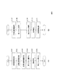
図1は、従来の多段ベクトル量子化手法を用いた符号化器と復号器の機能構成例を示す図である。図2は従来の多段ベクトル量子化手法を用いた符号化器と復号器の処理フローを示す図である。図2(A)は符号化器の処理フローを示しており、図2(B)は復号器の処理フローを示している。多段ベクトル量子化では、量子化部が多段に接続され、初段の第1量子化部は入力信号について動作し,次段以降は入力信号と前段までの量子化出力の誤差について動作する。このようにすると、メモリ量や演算量を現実的な範囲に抑えたままで、ベクトル量子化が可能となる。図中の多段ベクトル量子化の段数は、分かり易くするため2としてあるが、段数は2以上を用いた構成でも良い。量子化手法には、周波数領域に変換した成分を量子化する手法(非特許文献1)を例として用いた。 FIG. 1 is a diagram illustrating a functional configuration example of an encoder and a decoder using a conventional multistage vector quantization method. FIG. 2 is a diagram showing a processing flow of an encoder and a decoder using a conventional multistage vector quantization method. FIG. 2A shows a processing flow of the encoder, and FIG. 2B shows a processing flow of the decoder. In multi-stage vector quantization, quantizers are connected in multiple stages, the first stage first quantizer operates on the input signal, and the subsequent stages operate on errors between the input signal and the quantized output up to the previous stage. In this way, it is possible to perform vector quantization while keeping the memory amount and calculation amount within a practical range. The number of stages of multistage vector quantization in the figure is 2 for the sake of clarity, but a configuration using two or more stages may be used. As a quantization method, a method (Non-Patent Document 1) for quantizing a component converted into a frequency domain is used as an example.
符号化器100は、周波数領域変換部101、正規化基準値計算部102、正規化基準値量子化部103、第1ベクトル量子化部104、誤差計算部105、第2ベクトル量子化部106を備える。復号器100’は、正規化基準値復号部107、第1ベクトル復号部108、第2ベクトル復号部109、誤差修正部110、時間領域変換部111を備える。
The encoder 100 includes a frequency
周波数領域変換部101は、時系列信号である時間領域の入力信号x(n)(音響信号等)を入力とし、所定の離散時間区間内のN個の入力信号x(0)(n=0,...,N−1)ごと(フレームごと)に、L点の周波数成分を示す信号である周波数領域信号X(k)(k=0,...,L−1)を生成し、これらを出力する(S101)。ただし、nは時間領域での信号の番号(離散時間番号)を、kは周波数領域での信号の番号(離散周波数番号)を示している。高い周波数に対応する離散周波数番号kほど値が大きい。N,Lは、2以上の整数であり、例えば64や80である。N,Lは、符号化器100および復号器100’で共有される値である。また、周波数領域変換方法としては、例えばMDCT(Modified Discrete Cosine Transform)がある。
The frequency
正規化基準値計算部102は、第1符号化対象信号である周波数領域信号X(k)(k=0,...,L−1)を入力として、周波数領域信号X(k)(k=0,...,L−1)の正規化基準値X− 0を生成して出力する(S102)。なお、正規化基準値X− 0は、S個(L≧S≧2)の周波数領域信号X(k)の振幅値からなる集合に依存する信号であり、その例は、L点または各サブバンド(L点をさらに分割した周波数帯域で、例えば8点で1つのサブバンドを形成する)内の周波数領域信号X(k)のパワーの平均値の平方根である。Sの例は、Lや1つのサブバンドのサンプル点数などである。また、例えば、L点の正規化基準値X− 0は、次式のように計算される。
The normalization reference
また、L点または各サブバンド内の周波数領域信号X(k)の平均振幅値を正規化基準値X− 0としてもよい。例えば、L点の正規化基準値X− 0を Further, the average amplitude value of the frequency domain signal X (k) in the L point or each subband may be set as the normalized reference value X - 0 . For example, L point normalization reference value X - 0
としてもよい。
It is good.
以下の説明では、サブバンドでの正規化ではなく、L点の正規化基準値X− 0を用いた場合について説明する。なお、記述の制約上、X− 0と表現する場合があるが、X− 0と In the following description, a case where the L-point normalization reference value X - 0 is used instead of the subband normalization will be described. Incidentally, the description constraints, X - but may be expressed as 0, X - 0
![]()
![]()
とは同じものをさす。同様に、以下で用いる、X−,X^(k),E^(k)は、それぞれ、 Means the same thing. Similarly, X − , X ^ (k), and E ^ (k) used below are respectively
![]()
と同じものをさす。
![]()
The same thing as.
正規化基準値量子化部103は、正規化基準値計算部102で求めた正規化基準値X− 0を入力とし、正規化基準値X− 0を量子化して、正規化基準値量子化インデックスCSと、正規化基準値量子化インデックスCSに対応する量子化正規化基準値X−を出力する(S103)。
The normalization reference
第1ベクトル量子化部104は、各周波数領域信号X(k)と量子化正規化基準値X−を入力として、各周波数領域信号X(k)を、量子化正規化基準値X−で割り算する、もしくは逆数を乗ずることで正規化し、正規化周波数領域信号を求める。そして、正規化周波数領域信号をベクトル量子化して、量子化代表ベクトルのインデックスである第1ベクトル量子化インデックスC1と、第1ベクトル量子化インデックスC1に対応する量子化信号の逆正規化値(量子化インデックスC1に対応する量子化信号と量子化正規化基準値X−との積)である第1量子化信号X^(k)を求め、第1ベクトル量子化インデックスC1と第1量子化信号X^(k)出力する(S104)。
The first
誤差計算部105は、周波数領域信号X(k)と第1量子化信号X^(k)を入力として、周波数領域信号X(k)と第1量子化信号X^(k)の間の誤差を、例えば、
E(k)=X(k)−X^(k)
のように計算し、第2符号化対象信号である誤差信号E(k)を出力する(S105)。
The
E (k) = X (k) -X ^ (k)
The error signal E (k) that is the second encoding target signal is output (S105).
第2ベクトル量子化部106は、誤差信号E(k)と量子化正規化基準値X−を入力とし、誤差信号E(k)を、量子化正規化基準値X−で割り算する、もしくは逆数を乗ずることで正規化し、正規化誤差信号を求める。そして、正規化誤差信号をベクトル量子化して、量子化代表ベクトルのインデックスを第2ベクトル量子化インデックスC2として出力する(S106)。
Second
符号化器100は、第1ベクトル量子化インデックスC1と第2ベクトル量子化インデックスC2と正規化基準値量子化インデックスCSが含まれる符号を、復号器100’に送る。そして、復号器100’では、以下のような処理が行われる。 Encoder 100, a code included first vector quantization index C 1 and the second vector quantization index C 2 and the normalized reference value quantization index C S, and sends to the decoder 100 '. The decoder 100 ′ performs the following processing.
正規化基準値復号部107は、正規化基準値量子化インデックスCSを入力とし、正規化基準値量子化インデックスCSに対応する復号量子化正規化基準値X−を求め、この復号量子化正規化基準値X−を出力する(S107)。
Normalized reference
第1ベクトル復号部108は、第1ベクトル量子化インデックスC1と復号量子化正規化基準値X−を入力とし、第1ベクトル量子化インデックスC1を復号し、フレーム単位の正規化された信号を正規化第1量子化信号として求め、正規化第1量子化信号に復号量子化正規化基準値X−を乗算することで逆正規化し、これを復号第1量子化信号X^(k)(量子化信号)として出力する(S108)。
The first
第2ベクトル復号部109は、第2ベクトル量子化インデックスC2と復号量子化正規化基準値X−を入力とし、第2ベクトル量子化インデックスC2を復号し、正規化された信号を正規化誤差信号として求め、正規化誤差信号に復号量子化正規化基準値X−を乗算することで逆正規化し、これを復号量子化誤差信号E^(k)として出力する(S109)。
Second
誤差修正部110は、復号第1量子化信号X^(k)と復号量子化誤差信号E^(k)を入力とし、復号信号Z(k)を、例えば、
Z(k)=X^(k)+E^(k) (3)
のように求め、復号信号Z(k)を出力する(S110)。
The
Z (k) = X ^ (k) + E ^ (k) (3)
Thus, the decoded signal Z (k) is output (S110).
時間領域変換部111は、復号信号Z(k)(k=0,...,L−1)を入力とし、例えばフレーム点数L分の逆MDCTを用いて時間領域変換を行い、フレーム点数L分の出力信号z(n)(n=0,...,N−1)を出力する(S111)。
The time
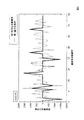
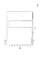
図3は、従来の多段ベクトル量子化手法を概念的に説明するための図である。横軸は周波数成分の番号、縦軸は各周波数成分の値(例えば、MDCT係数)を示している。この図に例示する第1符号化対象信号は、周波数領域信号X(k)であり、破線で示されている。また、初段のベクトル量子化後の信号である第1量子化信号X^(k)は、実線で示されている。量子化に必要なビット数に対して予め定められた量子化ビット数が不足すると、振幅値が0の第1量子化信号X^(k)が多数発生する。従来の後段のベクトル量子化では、図の第1符号化対象信号である周波数領域信号X(k)と第1量子化信号X^(k)との差分をベクトル量子化している。 FIG. 3 is a diagram for conceptually explaining a conventional multistage vector quantization method. The horizontal axis indicates the frequency component number, and the vertical axis indicates the value of each frequency component (for example, MDCT coefficient). The first encoding target signal illustrated in this figure is a frequency domain signal X (k), which is indicated by a broken line. The first quantized signal X ^ (k), which is the signal after the first stage vector quantization, is indicated by a solid line. When the predetermined number of quantization bits is insufficient with respect to the number of bits necessary for quantization, a large number of first quantized signals X ^ (k) having an amplitude value of 0 are generated. In the conventional latter-stage vector quantization, the difference between the frequency domain signal X (k) and the first quantized signal X ^ (k), which is the first signal to be encoded, is vector quantized.
なお、上記では、周波数領域信号X(k)を第1符号化対象信号とし、周波数領域信号X(k)を第1ベクトル量子化部104、正規化基準値計算部102および誤差計算部105に入力する構成を示した。しかし、時間領域の入力信号x(n)を第1符号化対象信号とし、周波数領域信号X(k)の代わりに入力信号x(n)を第1ベクトル量子化部104、正規化基準値計算部102および誤差計算部105に入力する構成であってもよい。この場合、周波数領域変換部101および時間領域変換部111は不要となり、上述の周波数領域信号X(k)を入力信号x(n)に置換した処理が実行される。
In the above description, the frequency domain signal X (k) is the first signal to be encoded, and the frequency domain signal X (k) is sent to the first
上述の符号化器100と復号器100’では、量子化に必要なビット数に対して、予め定められた量子化ビット数が不足すると、入力信号に存在するはずの周波数成分が出力信号には存在しない(出力信号から周波数成分が欠損する)という頻度が高くなる。このように出力信号から周波数成分が欠損した場合、出力信号の或る周波数成分の有無が時間的に不連続に変化する頻度が高くなる。人間は、このような周波数成分の有無の時間的に不連続な変化に敏感であり、このような変化はミュージカルノイズと呼ばれるノイズとして知覚される場合がある。 In the encoder 100 and the decoder 100 ′ described above, if the predetermined number of quantization bits is insufficient with respect to the number of bits necessary for quantization, the frequency component that should exist in the input signal is included in the output signal. The frequency of non-existence (frequency component is lost from the output signal) increases. When the frequency component is lost from the output signal in this way, the frequency with which the presence or absence of a certain frequency component of the output signal changes discontinuously increases. Humans are sensitive to temporally discontinuous changes in the presence or absence of such frequency components, and such changes may be perceived as noise called musical noise.
しかしながら、従来の符号化器100と復号器100’は、第1量子化信号の値(前段のベクトル量子化で得られた量子化された信号の値)が0か0以外かに関係なく、第1量子化信号と符号化対象信号との誤差を示す信号を後段のベクトル量子化の対象としている。つまり、従来技術には、ミュージカルノイズのような人間が敏感に感じるノイズを軽減すための特別な工夫はない。したがって、元の信号と復号された信号との誤差のパワーが数値の上では小さくなったとしても、人間の感覚が敏感な誤差に着目した符号化ではないので、ミュージカルノイズが残りやすいという課題がある。このようなミュージカルノイズの問題は、周波数領域信号X(k)を符号化対象信号とした場合に特に顕著となるが、時間領域の入力信号x(n)を符号化対象信号とする場合にも存在する。 However, the conventional encoder 100 and decoder 100 ′ are independent of whether the value of the first quantized signal (the value of the quantized signal obtained by the previous vector quantization) is 0 or other than 0, A signal indicating an error between the first quantized signal and the encoding target signal is set as a vector quantization target in the subsequent stage. That is, there is no special device in the prior art for reducing noise that humans feel sensitive like musical noise. Therefore, even if the power of error between the original signal and the decoded signal is small in numerical value, it is not an encoding that focuses on errors that are sensitive to human senses, so there is a problem that musical noise tends to remain. is there. Such a problem of musical noise is particularly noticeable when the frequency domain signal X (k) is an encoding target signal, but also when the time domain input signal x (n) is an encoding target signal. Exists.
一方、量子化に必要なビット数は第1符号化対象信号の種類に応じて異なり、第1符号化対象信号の種類によっては、上述の符号化器100と復号器100’との構成でもミュージカルノイズがさほど問題とならず、符号化精度の面からは、むしろ符号化器100と復号器100’との構成が好ましい場合もある。このように、第1符号化対象信号の種類に応じて最適な符号化方式および復号方式は異なる。 On the other hand, the number of bits required for quantization differs depending on the type of the first encoding target signal. Depending on the type of the first encoding target signal, the configuration of the encoder 100 and decoder 100 ′ described above may be musical. Noise does not matter so much, and the configuration of the encoder 100 and the decoder 100 ′ may be preferable from the viewpoint of encoding accuracy. Thus, the optimal encoding scheme and decoding scheme differ depending on the type of the first encoding target signal.
本発明は、このような課題に鑑みてなされたものであり、十分な符号ビット長を確保できない場合であっても、第1符号化対象信号の種類に応じ、適切にミュージカルノイズを軽減できる技術を提供することを目的とする。 The present invention has been made in view of such problems, and even when a sufficient code bit length cannot be ensured, a technique that can appropriately reduce musical noise according to the type of the first encoding target signal. The purpose is to provide.
本発明の符号化処理では、所定数(所定サンプル数)の第1符号化対象信号またはそれらに対応する所定数の信号、を要素とするベクトルを量子化し、第1符号化対象信号にそれぞれ対応する第1量子化信号と、当該第1量子化信号を特定するための第1量子化インデックスとを生成して出力し、上記所定数の第1符号化対象信号のうち、基準値よりも振幅値が小さな第1符号化対象信号の個数、または、振幅値が基準値以下の第1符号化対象信号の個数、を特定する判定値に基づき、所定数の第1符号化対象信号に対応する符号化方式を選択し、選択した符号化方式を特定するためのモード情報を生成して出力し、第1量子化信号を少なくとも用い、選択された符号化方式に則って符号化処理を行う。 In the encoding process of the present invention, a vector having elements of a predetermined number (predetermined number of samples) of the first encoding target signal or a predetermined number of signals corresponding thereto is quantized to correspond to each of the first encoding target signals. A first quantized signal to be generated and a first quantized index for specifying the first quantized signal are generated and output, and the amplitude of the predetermined number of first encoding target signals is larger than a reference value. Corresponding to a predetermined number of first encoding target signals based on a determination value that specifies the number of first encoding target signals having a small value or the number of first encoding target signals having an amplitude value equal to or smaller than a reference value. A coding method is selected, mode information for specifying the selected coding method is generated and output, and at least the first quantized signal is used to perform coding processing according to the selected coding method.
また、本発明の復号処理では、少なくとも第1量子化インデックスを復号して所定数の第1量子化信号を得、少なくともモード情報を用いて復号方式を特定し、特定された復号方式に則り、少なくとも第1量子化値を用いて復号信号を生成し、生成した復号信号を出力する。 Further, in the decoding process of the present invention, at least the first quantization index is decoded to obtain a predetermined number of first quantized signals, at least the mode information is used to identify the decoding method, and in accordance with the specified decoding method, A decoded signal is generated using at least the first quantized value, and the generated decoded signal is output.
通常、上記所定数の第1符号化対象信号のうち振幅値が小さなものが多い場合(「スパース」と呼ぶ)、上記所定数の第1符号化対象信号の量子化に必要なビット数は少ない。この場合には、量子化に必要なビット数に対して、予め定められた量子化ビット数が不足する頻度が低くなるため、ミュージカルノイズはさほど問題にならない場合が多い。一方、上記所定数の第1符号化対象信号のうち振幅値が大きなものが多い場合、上記所定数の第1符号化対象信号の量子化に必要なビット数は多い。この場合には、量子化に必要なビット数に対して、予め定められた量子化ビット数が不足する頻度が高くなるため、ミュージカルノイズの問題が顕著となる。この場合には、ミュージカルノイズを軽減させることが可能な符号化方式および復号方式を用いることが望ましい。本発明は、基準値よりも振幅値が小さな第1符号化対象信号の個数、または、振幅値が基準値以下の第1符号化対象信号の個数を特定する判定値に基づき、少なくとも、上記所定数の第1符号化対象信号がスパースであるか否かを判定し、上記所定数の第1符号化対象信号に対応する符号化方式および復号方式を選択する。 Usually, when the predetermined number of first encoding target signals have many small amplitude values (referred to as “sparse”), the number of bits required for quantization of the predetermined number of first encoding target signals is small. . In this case, since the frequency with which the predetermined number of quantization bits is insufficient with respect to the number of bits necessary for quantization is low, musical noise is not often a problem. On the other hand, when many of the predetermined number of first encoding target signals have large amplitude values, the number of bits required for quantization of the predetermined number of first encoding target signals is large. In this case, the frequency of the predetermined number of quantization bits becomes insufficient with respect to the number of bits necessary for quantization, so the problem of musical noise becomes significant. In this case, it is desirable to use an encoding method and a decoding method that can reduce musical noise. The present invention is based on at least the predetermined value based on the number of first encoding target signals having an amplitude value smaller than the reference value or the determination value that specifies the number of first encoding target signals having an amplitude value equal to or less than the reference value. It is determined whether or not a number of first encoding target signals are sparse, and an encoding scheme and a decoding scheme corresponding to the predetermined number of first encoding target signals are selected.
本発明では、十分な符号ビット長を確保できない場合であっても、第1符号化対象信号の種類に応じ、適切にミュージカルノイズを軽減できる。 In the present invention, even when a sufficient code bit length cannot be ensured, musical noise can be appropriately reduced according to the type of the first encoding target signal.
以下、本発明の実施形態を詳細に説明する。なお、同じ機能を有する構成部には同じ番号を付し、重複説明を省略する。 Hereinafter, embodiments of the present invention will be described in detail. In addition, the same number is attached | subjected to the structure part which has the same function, and duplication description is abbreviate | omitted.
〔原理〕
まず、本形態の原理を説明する。
〔principle〕
First, the principle of this embodiment will be described.
上述のように、本形態では、少なくとも、上記所定数の第1符号化対象信号がスパースであるか否かを判定し、上記所定数の第1符号化対象信号に対応する符号化方式および復号方式を選択する。本形態では、4種類の符号化方式および復号方式の中から適切な符号化方式および復号方式を選択する。まず、これらの4種類の符号化方式および復号方式を説明する。 As described above, in the present embodiment, at least whether or not the predetermined number of first encoding target signals is sparse, and the encoding scheme and decoding corresponding to the predetermined number of first encoding target signals are determined. Select a method. In this embodiment, an appropriate encoding method and decoding method are selected from four types of encoding methods and decoding methods. First, these four types of encoding methods and decoding methods will be described.
なお、いずれの符号化方式も、所定数の第1符号化対象信号またはそれらに対応する所定数の信号、を要素とするベクトルを量子化し、第1符号化対象信号にそれぞれ対応する第1量子化信号と、当該第1量子化信号を特定するための第1量子化インデックスと、を生成することを前提した方式である。また、いずれの復号方式も、少なくとも第1量子化インデックスを復号して所定数の第1量子化信号を得ることを前提した方式である。また、各方式を識別子modeで表現する。 In any of the encoding schemes, a vector having elements of a predetermined number of first encoding target signals or a predetermined number of signals corresponding thereto is quantized, and the first quantum corresponding to each of the first encoding target signals. This is a scheme premised on generating a quantized signal and a first quantization index for specifying the first quantized signal. Each of the decoding schemes is based on the assumption that at least the first quantization index is decoded to obtain a predetermined number of first quantized signals. Each method is expressed by an identifier mode.
<第1符号化方式および第1復号方式(mode=0b)>
第1符号化方式は、第1符号化対象信号と第1量子化信号とから求めた誤差信号を第2符号化対象信号とし、当該第2符号化対象信号を量子化し、その量子化信号を特定するための第2量子化インデックスを生成して出力する方式である。また、これに対応する第1復号方式は、少なくとも第2量子化インデックスを用いて所定数の第2量子化信号を復号し、当該第2量子化信号を誤差信号として第1量子化信号を誤差修正することで復号信号を生成する方式である。第1符号化方式および第1復号方式の具体例は、図1から図3を用いて説明した上述の符号化器100および復号器100’が実行する符号化方式および復号方式である。第1符号化方式および第1復号方式を総称して第1方式と呼び、それに対応する識別子modeの値を「0b」とする。
<First encoding scheme and first decoding scheme (mode = 0b)>
The first encoding method uses an error signal obtained from the first encoding target signal and the first quantized signal as a second encoding target signal, quantizes the second encoding target signal, and converts the quantized signal to This is a method of generating and outputting a second quantization index for specifying. In addition, the first decoding method corresponding to this decodes a predetermined number of second quantized signals using at least the second quantization index, and uses the second quantized signal as an error signal to convert the first quantized signal into an error. This is a method of generating a decoded signal by correcting the signal. Specific examples of the first encoding method and the first decoding method are the encoding method and decoding method executed by the encoder 100 and the decoder 100 ′ described above with reference to FIGS. The first encoding method and the first decoding method are collectively referred to as the first method, and the value of the identifier mode corresponding to the first method is set to “0b”.
<第2符号化方式および第2復号方式(mode=0a)>
第2符号化方式は、振幅値が0の第1量子化信号に対応する第1符号化対象信号のみを第2符号化対象信号とし、当該第2符号化対象信号を量子化し、その量子化信号を特定するための第2量子化インデックスを生成して出力する方式である。また、これに対応する第2復号方式は、少なくとも第2量子化インデックスを用いて所定数の第2量子化信号を復号し、当該第2量子化信号またはそれと同値の信号と、振幅値が0でない第1量子化信号と、を含む復号信号を生成する方式である。第2符号化方式および第2復号方式を総称して第2方式と呼び、それに対応する識別子modeの値を「0a」とする。
<Second encoding scheme and second decoding scheme (mode = 0a)>
In the second encoding method, only the first encoding target signal corresponding to the first quantized signal having an amplitude value of 0 is used as the second encoding target signal, the second encoding target signal is quantized, and the quantization is performed. In this method, a second quantization index for specifying a signal is generated and output. Also, the second decoding method corresponding to this decodes a predetermined number of second quantized signals using at least the second quantization index, and the second quantized signal or a signal having the same value as that of the second quantized signal has an amplitude value of 0. This is a method for generating a decoded signal including the first quantized signal that is not. The second encoding method and the second decoding method are collectively referred to as the second method, and the value of the identifier mode corresponding to the second method is set to “0a”.
上述の第1符号化方式では、第1符号化対象信号と第1量子化信号とから求めた誤差信号を第2符号化対象信号とし、当該第2符号化対象信号を量子化していた。この方式において、第1符号化対象信号と振幅値が0以外の第1量子化信号との誤差が大きい場合、これらに対応するレベルの大きな誤差信号の量子化精度を優先した量子化を行う必要がある。レベルの小さな信号の量子化誤差を小さくするよりも、レベルの大きな信号の量子化誤差を小さくするほうが重要だからである。そのため、第2ベクトル量子化インデックスに割り当てられたビット数が制限された環境においては、振幅値が0の第1量子化信号に対応するレベルの小さな誤差信号に割り当てられる第2ベクトル量子化インデックスの種類が少なくなる。その結果、レベルの小さな誤差信号に対応する量子化信号の振幅が0なる頻度が高くなり、振幅値が0の周波数成分が多い復号信号になってしまう。これは、ミュージカルノイズの原因の1つとなる。 In the first encoding method described above, the error signal obtained from the first encoding target signal and the first quantized signal is used as the second encoding target signal, and the second encoding target signal is quantized. In this method, when the error between the first encoding target signal and the first quantized signal having an amplitude value other than 0 is large, it is necessary to perform quantization giving priority to the quantization accuracy of the error signal having a large level corresponding thereto. There is. This is because it is more important to reduce the quantization error of a signal having a large level than to reduce the quantization error of a signal having a small level. Therefore, in an environment where the number of bits assigned to the second vector quantization index is limited, the second vector quantization index assigned to the small error signal corresponding to the first quantized signal having an amplitude value of 0 There are fewer types. As a result, the frequency with which the amplitude of the quantized signal corresponding to the error signal with a small level becomes zero increases, and the decoded signal has many frequency components with an amplitude value of zero. This is one of the causes of musical noise.
これに対し、第2符号化方式では、振幅値が0の第1量子化信号に対応する第1符号化対象信号のみを第2符号化対象信号とし、当該第2符号化対象信号を量子化する。つまり、振幅値が0の第1量子化信号に対応する第1符号化対象信号だけを量子化するので、第2ベクトル量子化インデックスに割り当てられたビット数が制限される環境であっても、振幅値が0の第1量子化信号に対応するレベルの小さな誤差信号に割り当てられる第2ベクトル量子化インデックスの種類が多くなる。その結果、レベルの小さな誤差信号に対応する量子化信号の振幅が0なる頻度が低くなり、ミュージカルノイズを軽減できる。 On the other hand, in the second encoding method, only the first encoding target signal corresponding to the first quantized signal whose amplitude value is 0 is set as the second encoding target signal, and the second encoding target signal is quantized. To do. That is, since only the first encoding target signal corresponding to the first quantized signal whose amplitude value is 0 is quantized, even in an environment where the number of bits allocated to the second vector quantization index is limited, The types of second vector quantization indexes assigned to error signals with small levels corresponding to the first quantized signal having an amplitude value of 0 increase. As a result, the frequency with which the amplitude of the quantized signal corresponding to an error signal with a low level becomes zero decreases, and musical noise can be reduced.
図4は、第2方式の原理を説明するための図である。図4は、L=64の場合の周波数領域信号X(k)(k=0,...,L−1)を各第1符号化対象信号とした場合の例である。図4の横軸は離散周波数番号kを示し、縦軸は周波数成分の値(例えば、MDCT係数)を示す。図4の破線は、第1符号化対象信号である周波数領域信号X(k)を例示し、太い実線は、第1符号化対象信号に対応する量子化信号である第1量子化信号X^(k)を例示する。図4の例では、「Z」で示す振幅値が0の第1量子化信号X^(k)のみを第2符号化対象信号とし、当該第2符号化対象信号を量子化し、その量子化信号を特定するための第2量子化インデックスを生成する。 FIG. 4 is a diagram for explaining the principle of the second method. FIG. 4 shows an example in which the frequency domain signal X (k) (k = 0,..., L−1) when L = 64 is used as each first encoding target signal. The horizontal axis in FIG. 4 indicates the discrete frequency number k, and the vertical axis indicates the value of the frequency component (for example, MDCT coefficient). The broken line in FIG. 4 illustrates the frequency domain signal X (k) that is the first encoding target signal, and the thick solid line indicates the first quantized signal X ^ that is the quantized signal corresponding to the first encoding target signal. (K) is illustrated. In the example of FIG. 4, only the first quantized signal X ^ (k) whose amplitude value indicated by “Z” is 0 is set as the second encoding target signal, the second encoding target signal is quantized, and the quantization is performed. A second quantization index for identifying the signal is generated.
<第3符号化方式および第3復号方式(mode=2)>
第3符号化方式は、第1量子化信号の振幅値が0の場合に、複数の第1符号化対象信号の振幅値からなる集合に依存する量子化正規化基準値と第1符号化対象信号の絶対値とから求めた誤差信号を第2符号化対象信号とし、第1量子化信号の振幅値が0以外の場合に、第1符号化対象信号の絶対値と第1量子化信号の絶対値とから求めた誤差信号を第2符号化対象信号とし、当該第2符号化対象信号を量子化し、その量子化信号を特定するための第2量子化インデックスを生成して出力する方式である。また、これに対応する第3復号方式は、少なくとも第2量子化インデックスを用いて所定数の第2量子化信号を復号し、少なくとも第3量子化インデックスを用いて量子化正規化基準値を復号し、第1量子化信号の振幅値が0の場合に、第2量子化信号を誤差信号として量子化正規化基準値を誤差修正することで復号信号を生成し、第1量子化信号の振幅値が0以外の場合に、第2量子化信号を誤差信号として第1量子化信号を誤差修正することで復号信号を生成する方式である。第3符号化方式および第3復号方式を総称して第3方式と呼び、それに対応する識別子modeの値を「2」とする。
<Third encoding scheme and third decoding scheme (mode = 2)>
In the third encoding method, when the amplitude value of the first quantized signal is 0, the quantization normalization reference value and the first encoding target that depend on the set of the amplitude values of the plurality of first encoding target signals When the error signal obtained from the absolute value of the signal is the second encoding target signal and the amplitude value of the first quantized signal is other than 0, the absolute value of the first encoding target signal and the first quantized signal An error signal obtained from the absolute value is used as a second encoding target signal, the second encoding target signal is quantized, and a second quantization index for specifying the quantized signal is generated and output. is there. The third decoding method corresponding to this decodes a predetermined number of second quantized signals using at least the second quantization index, and decodes the quantized normalization reference value using at least the third quantization index. When the amplitude value of the first quantized signal is 0, a decoded signal is generated by correcting the quantization normalization reference value using the second quantized signal as an error signal, and the amplitude of the first quantized signal When the value is other than 0, the decoded signal is generated by correcting the error of the first quantized signal using the second quantized signal as an error signal. The third encoding method and the third decoding method are collectively referred to as a third method, and the value of the identifier mode corresponding to the third method is set to “2”.
図5は、第3方式の原理を説明するための図である。図5は、L=64の場合の周波数領域信号X(k)(k=0,...,L−1)を各第1符号化対象信号とした場合の例である。図5の横軸は離散周波数番号kを示し、縦軸は周波数成分の値を示す。図5の細かい破線は、量子化正規化基準値X−を例示し、図5の粗い破線は、第1符号化対象信号である周波数領域信号の絶対値|X(k)|を例示し、太い実線は、第1符号化対象信号に対応する量子化信号である第1量子化信号の絶対値|X^(k)|を例示する。なお、図5の量子化正規化基準値X−は、8サンプルからなるサブベクトルごとに求めた例である。図5の例では、符号化処理において、第1量子化信号の振幅値|X^(k)|が0の場合(例えば、「Q1」)に、量子化正規化基準値X−と周波数領域信号の絶対値|X(k)|とから求めた誤差信号を第2符号化対象信号とし、第1量子化信号の振幅値|X^(k)|が0以外の場合(例えば、「Q2」)に、周波数領域信号の絶対値|X(k)|と第1量子化信号の絶対値|X^(k)|とから求めた誤差信号を第2符号化対象信号とする。 FIG. 5 is a diagram for explaining the principle of the third method. FIG. 5 shows an example in which the frequency domain signal X (k) (k = 0,..., L−1) when L = 64 is used as each first encoding target signal. The horizontal axis of FIG. 5 indicates the discrete frequency number k, and the vertical axis indicates the value of the frequency component. The fine broken line in FIG. 5 illustrates the quantization normalization reference value X −, and the coarse broken line in FIG. 5 illustrates the absolute value | X (k) | of the frequency domain signal that is the first encoding target signal, The thick solid line illustrates the absolute value | X ^ (k) | of the first quantized signal that is the quantized signal corresponding to the first encoding target signal. Note that the quantization normalization reference value X − in FIG. 5 is an example obtained for each subvector consisting of 8 samples. In the example of FIG. 5, in the encoding process, when the amplitude value | X ^ (k) | of the first quantized signal is 0 (for example, “Q1”), the quantization normalization reference value X − and the frequency domain When the error signal obtained from the absolute value | X (k) | of the signal is the second encoding target signal and the amplitude value | X ^ (k) | of the first quantized signal is other than 0 (for example, “Q2 )), An error signal obtained from the absolute value | X (k) | of the frequency domain signal and the absolute value | X ^ (k) | of the first quantized signal is set as a second encoding target signal.
図6および図7は、第3符号化方式および第3復号方式の手順を説明するための図である。図6および図7の横軸は離散周波数番号kを示し、縦軸は周波数成分の値を示す。図6の破線は、第1符号化対象信号である周波数領域信号の絶対値|X(k)|を例示し、太い実線は、第1符号化対象信号に対応する量子化信号である第1量子化信号の絶対値|X^(k)|を例示する。図7の細かい破線は、量子化正規化基準値X−を例示し、粗い破線は、第1符号化対象信号である周波数領域信号の絶対値|X(k)|を例示し、実線は、第1符号化対象信号に対応する量子化信号である第1量子化信号の絶対値|X^(k)|を例示する。 6 and 7 are diagrams for explaining procedures of the third encoding method and the third decoding method. 6 and 7, the horizontal axis indicates the discrete frequency number k, and the vertical axis indicates the value of the frequency component. The broken line in FIG. 6 illustrates the absolute value | X (k) | of the frequency domain signal that is the first encoding target signal, and the thick solid line is the first quantized signal corresponding to the first encoding target signal. The absolute value | X ^ (k) | of the quantized signal is illustrated. The fine broken line in FIG. 7 illustrates the quantization normalization reference value X − , the coarse broken line illustrates the absolute value | X (k) | of the frequency domain signal that is the first encoding target signal, and the solid line represents The absolute value | X ^ (k) | of the first quantized signal that is the quantized signal corresponding to the first encoding target signal is illustrated.
第3符号化方式では、初段のベクトル量子化後に、図6のように、第1符号化対象信号である周波数領域信号X(k)と第1量子化信号X^(k)とを絶対値で表す。そして、図7に示すように、8サンプルからなるサブベクトルごとに量子化正規化基準値X−を求める。この図からも、振幅値が0の第1量子化信号の絶対値|X^(k)|と第1符号化対象信号である周波数領域信号の絶対値|X(k)|との誤差よりも、量子化正規化基準値X−と第1符号化対象信号である周波数領域信号X(k)の絶対値|X(k)|との差分の方が小さいことが分かる。したがって、第1量子化信号の振幅値|X^(k)|が0のときには、第1符号化対象信号である周波数領域信号の絶対値|X(k)|と量子化正規化基準値X−との差分を後段でベクトル量子化する方が効率的である。また、量子化正規化基準値X−は、復号器が前段のベクトル復号に利用する情報であり、量子化正規化基準値X−を後段の符号化に利用しても復号器に新たな情報を伝える必要はない。 In the third encoding method, after the first-stage vector quantization, as shown in FIG. 6, the frequency domain signal X (k) and the first quantized signal X ^ (k), which are the first encoding target signals, are absolute values. Represented by Then, as shown in FIG. 7, a quantization normalization reference value X − is obtained for each subvector consisting of 8 samples. Also from this figure, from the error between the absolute value | X ^ (k) | of the first quantized signal whose amplitude value is 0 and the absolute value | X (k) | of the frequency domain signal that is the first encoding target signal. also, the quantization normalized reference value X - absolute value of the frequency domain signal X is first coded signal (k) | seen that towards the difference is smaller | X (k). Therefore, when the amplitude value | X ^ (k) | of the first quantized signal is 0, the absolute value | X (k) | of the frequency domain signal that is the first encoding target signal and the quantization normalization reference value X It is more efficient to vector-quantize the difference from − in the latter stage. The quantization normalization reference value X − is information used by the decoder for the preceding vector decoding, and new information is added to the decoder even if the quantization normalization reference value X − is used for the subsequent encoding. There is no need to tell.
なお、図7では8サンプルからなるサブベクトルごとに量子化正規化基準値X−を求めているが、64サンプルで1つの量子化正規化基準値X−を求めてもよいし、他の数ごとに量子化正規化基準値X−を求めてもよい。ただし、適当なサンプル数を選ごとに量子化正規化基準値X−を求めれば、量子化正規化基準値X−と第1符号化対象信号との差分を小さくできる。 In FIG. 7, the quantization normalization reference value X − is obtained for each subvector consisting of 8 samples. However, one quantization normalization reference value X − may be obtained with 64 samples, or other numbers. quantization normalized reference value X in each - may be obtained. However, if the quantization normalization reference value X − is obtained for each selection of an appropriate number of samples, the difference between the quantization normalization reference value X − and the first encoding target signal can be reduced.
図8は、第1符号化対象信号の例と第3符号化方式の第2符号化対象信号を生成するための基準となる信号の例とを比較するための図である。図8の破線は、第1符号化対象信号である周波数領域信号の絶対値|X(k)|を例示し、実線は、第1量子化信号X^(k)の振幅値が0以外のときには第1量子化信号の絶対値とし、第1量子化信号X^(k)の振幅値が0のときには量子化正規化基準値X−とした値(第2符号化対象信号を生成するための基準)を例示する。この図から、破線で例示する第1符号化対象信号の絶対値と、実線で例示する第2符号化対象信号を生成するための基準との差分を第2符号化対象信号とすれば、第2符号化対象信号の振幅値を小さくできることがわかる。第2符号化対象信号の振幅値が小さいほど、その量子化に必要なビット数は少なくて済むことから、第3符号化方式および第3復号方式ではミュージカルノイズを軽減できる。 FIG. 8 is a diagram for comparing an example of the first encoding target signal and an example of a signal serving as a reference for generating the second encoding target signal of the third encoding scheme. The broken line in FIG. 8 illustrates the absolute value | X (k) | of the frequency domain signal that is the first encoding target signal, and the solid line indicates that the amplitude value of the first quantized signal X ^ (k) is other than zero. sometimes the absolute value of the first quantized signal, the amplitude value of the first quantized signal X ^ (k) is quantized normalized reference value X when the 0 - for generating the value (second coded signal For example). From this figure, if the difference between the absolute value of the first encoding target signal illustrated by the broken line and the reference for generating the second encoding target signal illustrated by the solid line is the second encoding target signal, 2 that the amplitude value of the signal to be encoded can be reduced. The smaller the amplitude value of the second encoding target signal is, the smaller the number of bits required for the quantization is. Therefore, musical noise can be reduced in the third encoding method and the third decoding method.
<第4符号化方式および第4復号方式(mode=1)>
第4符号化方式は、振幅値が0の第1量子化信号に対応する第1符号化対象信号のみについて、第1符号化対象信号が正であるか負であるかを示す正負符号情報を生成する方式である。これに対応する第4復号方式は、少なくとも正負符号情報を用いて当該正負符号情報が示す正または負の符号を持つ信号を生成し、当該正または負の符号を持つ信号またはそれと同値の信号と、振幅値が0でない第1量子化信号と、を含む復号信号を生成する方式である。第4符号化方式および第4復号方式を総称して第4方式と呼び、それに対応する識別子modeの値を「1」とする。
<Fourth encoding scheme and fourth decoding scheme (mode = 1)>
In the fourth encoding method, positive / negative sign information indicating whether the first encoding target signal is positive or negative for only the first encoding target signal corresponding to the first quantized signal whose amplitude value is 0. It is a method to generate. The fourth decoding method corresponding to this generates a signal having a positive or negative sign indicated by the positive / negative sign information using at least the positive / negative sign information, and a signal having the positive or negative sign or a signal having the same value as the signal. And a first quantized signal whose amplitude value is not 0. The fourth encoding method and the fourth decoding method are collectively referred to as a fourth method, and the value of the identifier mode corresponding thereto is “1”.
図9は、第4符号化方式の原理を説明するための図である。図9は、L=64の場合の周波数領域信号X(k)(k=0,...,L−1)を各符号化対象信号とした場合の例である。図9の横軸は離散周波数番号kを示し、縦軸は周波数成分の値を示す。図9の破線は、符号化対象信号である周波数領域信号X(k)を例示し、太い実線は、符号化対象信号に対応する量子化信号である第1量子化信号X^(k)を例示する。 FIG. 9 is a diagram for explaining the principle of the fourth encoding method. FIG. 9 shows an example in which the frequency domain signal X (k) (k = 0,..., L−1) when L = 64 is used as each encoding target signal. The horizontal axis in FIG. 9 indicates the discrete frequency number k, and the vertical axis indicates the value of the frequency component. The broken line in FIG. 9 illustrates the frequency domain signal X (k) that is the signal to be encoded, and the thick solid line represents the first quantized signal X ^ (k) that is the quantized signal corresponding to the signal to be encoded. Illustrate.
図9に例示するように、第4符号化方式では、振幅が0となる第1量子化信号X^(k)に対し、当該第1量子化信号X^(k)に対応する第1符号化対象信号である周波数領域信号X(k)が正であるか負であるかを示す正負符号情報(例えば、MDCT係数の正負の符号情報)を生成し、これを符号の一部とする。 As illustrated in FIG. 9, in the fourth encoding method, the first code corresponding to the first quantized signal X ^ (k) with respect to the first quantized signal X ^ (k) having an amplitude of 0. The sign signal information indicating whether the frequency domain signal X (k) that is the signal to be converted is positive or negative (for example, the sign information of the MDCT coefficient) is generated and used as a part of the code.
図10は、第4復号方式の原理を説明するための図である。図10の横軸は離散周波数番号kを示し、縦軸は周波数成分の値を示す。図10の太字の破線は、符号化対象信号に対応する量子化信号である第1量子化信号X^(k)を例示し、細字の破線は、量子化正規化基準値X−とその負値-X−を例示し、太字の実線は復号信号を例示している。なお、図10の例では、8点の離散周波数点からなるサブバンドごとに量子化正規化基準値X−が生成されている。 FIG. 10 is a diagram for explaining the principle of the fourth decoding method. The horizontal axis of FIG. 10 indicates the discrete frequency number k, and the vertical axis indicates the value of the frequency component. Bold broken line in FIG. 10, illustrate ^ first quantized signal is quantized signals corresponding to the coded signal X (k), the dashed fine print is quantized normalized reference value X - and its negative values -X - illustrate, bold solid line illustrates the decoded signal. In the example of FIG. 10, a quantized normalization reference value X − is generated for each subband composed of 8 discrete frequency points.
図10に例示するように、第4復号方式では、少なくとも上記正負符号情報を用いて当該正負符号情報が示す正または負の符号を持つ信号を生成し、当該正または負の符号を持つ信号またはそれと同値の信号と、振幅値が0でない第1量子化信号X^(k)と、を含む復号信号を生成する。なお、図10の例では、正負符号情報が示す正または負の符号を持つ信号として、量子化正規化基準値X−と正負符号情報が示す正負符号との積からなる信号を用いている。 As illustrated in FIG. 10, in the fourth decoding scheme, a signal having a positive or negative sign indicated by the positive / negative sign information is generated using at least the positive / negative sign information, and a signal having the positive or negative sign or A decoded signal including the signal having the same value and the first quantized signal X ^ (k) whose amplitude value is not 0 is generated. In the example of FIG. 10, as a signal having a positive or negative sign indicating the sign information, quantized normalized reference value X - is used a signal consisting of the product of the sign indicated and sign information.
このように、第4方式では、復号信号の有無が時間的に不連続に変化する頻度を低くできるため、ミュージカルノイズを軽減できる。 Thus, in the fourth method, since the frequency with which the presence or absence of the decoded signal changes discontinuously in time can be lowered, musical noise can be reduced.
<第1符号化対象信号の性質と最適な方式との関係>
上述のように、第1方式はミュージカルノイズを軽減する対策が施されていないのに対し、第2〜4方式は、ミュージカルノイズを軽減する対策が施されている。
<Relationship between properties of first encoding target signal and optimum scheme>
As described above, the first method is not provided with a measure for reducing musical noise, whereas the second to fourth methods are provided with a measure for reducing musical noise.
しかしながら、符号化単位となる所定サンプルの第1符号化対象信号のうち、一部の第1符号化対象信号の振幅値のみが大きく、他の多くの第1符号化対象信号の振幅値がほぼ0の場合(第1符号化対象信号が非常にスパースである場合)、量子化に必要なビット数は非常に少なく、ミュージカルノイズはほとんど問題とならない。 However, only the amplitude values of some of the first encoding target signals are large among the first encoding target signals of predetermined samples serving as encoding units, and the amplitude values of many other first encoding target signals are almost the same. In the case of 0 (when the first encoding target signal is very sparse), the number of bits required for quantization is very small, and musical noise hardly causes a problem.
また、第2符号化方式では、振幅値が0の第1量子化信号のみを第2符号化対象信号とするため、第1符号化対象信号と振幅値が0以外の第1量子化信号との誤差が大きい場合には、第1方式よりも符号化精度が低下する。 In the second encoding method, since only the first quantized signal having an amplitude value of 0 is set as the second encoding target signal, the first encoding target signal and the first quantized signal having an amplitude value other than 0 are When the error is large, the encoding accuracy is lower than that in the first method.
また、第3方式では、第1符号化対象信号の絶対値、第1量子化信号の絶対値および量子化正規化基準値のような正負の情報を含まない情報から第2符号化対象信号を生成するため、振幅値が0の第1量子化信号に対応する第1符号化対象信号については正負の情報が符号化されない。また、第4方式では、振幅値が0の第1量子化信号X^(k)に対応する第1符号化対象信号の振幅値が符号化されない。そのため、第3方式や第4方式は、符号化単位となる所定サンプルの第1符号化対象信号のうち、一部の第1符号化対象信号の振幅値のみが大きく、他の多くの第1符号化対象信号の振幅値が0に近い場合(第1符号化対象信号がスパースである場合)に、第1方式や第2方式よりも符号化精度が悪くなる。また、第3方式では、前記第1量子化信号の振幅値が0の場合に、量子化正規化基準値と第1符号化対象信号の絶対値とから求めた誤差信号を第2符号化対象信号とするため、量子化正規化基準値に対する第1符号化対象信号の絶対値の統計的ばらつきが大きい場合でも精度よく符号化できる。 In the third method, the second encoding target signal is obtained from information that does not include positive and negative information such as the absolute value of the first encoding target signal, the absolute value of the first quantized signal, and the quantization normalization reference value. Therefore, positive / negative information is not encoded for the first encoding target signal corresponding to the first quantized signal having an amplitude value of 0. In the fourth method, the amplitude value of the first encoding target signal corresponding to the first quantized signal X ^ (k) having an amplitude value of 0 is not encoded. Therefore, in the third method and the fourth method, only the amplitude values of some of the first encoding target signals are large among the first encoding target signals of predetermined samples serving as encoding units, and many other first When the amplitude value of the encoding target signal is close to 0 (when the first encoding target signal is sparse), the encoding accuracy is worse than that of the first method or the second method. Further, in the third method, when the amplitude value of the first quantized signal is 0, an error signal obtained from the quantization normalization reference value and the absolute value of the first encoding target signal is used as the second encoding target. Since it is a signal, even when there is a large statistical variation in the absolute value of the first encoding target signal with respect to the quantization normalization reference value, encoding can be performed with high accuracy.
<第1符号化対象信号の性質に応じて方式選択>
以上のように、各方式は得手不得手があり、第1符号化対象信号の種類に応じて方式を使い分けることが望ましい。具体的には、第1符号化対象信号がスパース(例えば音声の母音の周波数領域信号)または非常にスパース(例えばサイン波の周波数領域信号)である場合には、第3方式や第4方式よりも第1方式や第2方式を用いる方が、高い精度で符号化できる。特に、第1符号化対象信号が非常にスパースである場合には、ミュージカルノイズはほとんど問題とならないため、第2方式よりも第1方式を用いる方が、高い精度で符号化できる。一方、第1符号化対象信号がスパースまたは非常にスパースでない場合(例えば、多重音源の楽音や環境雑音など)には、第1方式や第2方式よりも第3方式や第4方式を用いる方が、高い精度で符号化できる。特に、量子化正規化基準値に対する第1符号化対象信号の絶対値の統計的ばらつきが小さい場合には、第3方式よりも第4方式を用いる方が高い精度で符号化できる場合が多いが、この統計的ばらつきが大きい場合には、第4方式よりも第3方式を用いる方が高い精度で符号化できる場合が多い。
<Method selection according to the nature of the first signal to be encoded>
As described above, each method has advantages and disadvantages, and it is desirable to use different methods depending on the type of the first encoding target signal. Specifically, when the first encoding target signal is sparse (for example, a frequency domain signal of a voice vowel) or very sparse (for example, a frequency domain signal of a sine wave), the third method and the fourth method are used. Also, the first method and the second method can be encoded with higher accuracy. In particular, when the first signal to be encoded is very sparse, musical noise is hardly a problem, so that the first method can be encoded with higher accuracy than the second method. On the other hand, when the first encoding target signal is not sparse or very sparse (for example, music of multiple sound sources or environmental noise), the third method or the fourth method is used rather than the first method or the second method. Can be encoded with high accuracy. In particular, when the statistical variation of the absolute value of the first encoding target signal with respect to the quantization normalization reference value is small, it is often possible to encode with higher accuracy by using the fourth method than the third method. When this statistical variation is large, it is often possible to encode with higher accuracy by using the third method than by the fourth method.
本形態では、上述した第1符号化対象信号の性質に応じて方式を選択する。 In this embodiment, a method is selected according to the property of the first encoding target signal described above.
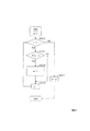
図11は、第1符号化対象信号の性質に応じて方式を選択する方法を説明するためのフローチャートである。 FIG. 11 is a flowchart for explaining a method of selecting a method according to the property of the first encoding target signal.
本形態では、まず、第1符号化対象信号がスパースであるかを確認する(S11/第1スパース性判定)。ステップS11での判定結果がYesであれば、次に、第1符号化対象信号が非常にスパースであるかを確認する(S12/第2スパース性判定)。ステップS12での結果がYesであれば、第1方式(mode=0b)が選択される(S13)。一方、ステップS12での結果がNoであれば、第2方式(mode=0a)が選択される(S14)。ステップS11での判定結果がNoであれば、次に、第1符号化対象信号の絶対値の量子化正規化基準値に対する統計的ばらつきは小さいことを確認する(S15/ばらつき判定)。ステップS15での判定結果がYesであれば、第4方式(mode=1)が選択される(S16)。一方、ステップS15での判定結果がNoであれば、第3方式(mode=2)が選択される(S17)。 In this embodiment, first, it is confirmed whether the first encoding target signal is sparse (S11 / first sparseness determination). If the determination result in step S11 is Yes, then it is confirmed whether the first encoding target signal is very sparse (S12 / second sparseness determination). If the result in step S12 is Yes, the first method (mode = 0b) is selected (S13). On the other hand, if the result in step S12 is No, the second method (mode = 0a) is selected (S14). If the determination result in step S11 is No, then it is confirmed that the statistical variation of the absolute value of the first encoding target signal with respect to the quantization normalization reference value is small (S15 / variation determination). If the determination result in step S15 is Yes, the fourth method (mode = 1) is selected (S16). On the other hand, if the determination result in step S15 is No, the third method (mode = 2) is selected (S17).
このように第1符号化対象信号の性質に応じて方式を選択することにより、十分な符号ビット長を確保できない場合であっても、第1符号化対象信号の種類に応じ、適切にミュージカルノイズを軽減できる。 Thus, even if it is not possible to ensure a sufficient code bit length by selecting a method according to the nature of the first encoding target signal, it is possible to appropriately select musical noise according to the type of the first encoding target signal. Can be reduced.
なお、ステップS11,S12の確認は、所定数の第1符号化対象信号のうち、基準値よりも振幅値が小さな第1符号化対象信号の個数、または、振幅値が基準値以下の第1符号化対象信号の個数、を特定する判定値に基づいて行うことができる。例えば、ステップS11の確認は、上記判定値と所定の閾値とを比較する閾値判定により、所定数の第1符号化対象信号の集合が、振幅値の小さな第1符号化対象信号が多い側のスパース分類に属するか、振幅値の小さな第1符号化対象信号が少ない側の非スパース分類に属するか、を判定することにより行うことができる。また、例えば、ステップS12の確認は、所定数の第1符号化対象信号にそれぞれ対応する第1量子化信号のうち振幅値が0の第1量子化信号の個数を特定する第2判定値と所定の第2閾値とを比較する閾値判定により、所定数の第1符号化対象信号にそれぞれ対応する第1量子化信号の集合が、振幅値が0の第1量子化信号の個数が多い側の第1分類に属するか、振幅値が0の第1量子化信号の個数が少ない側の第2分類に属するかを判定することにより行うことができる。また、ステップS15の確認は、例えば、所定数の第1符号化対象信号の振幅値の統計的ばらつきを特定する第3判定値と所定の第3閾値とを比較する閾値判定により、所定数の第1符号化対象信号の集合が、統計的ばらつきが大きい側の第3分類に属するか、統計的ばらつきが小さい側の第4分類に属するかを判定することにより行うことができる。 The confirmation in steps S11 and S12 is performed by checking the number of first encoding target signals whose amplitude value is smaller than the reference value among the predetermined number of first encoding target signals, or the first one whose amplitude value is equal to or less than the reference value. This can be performed based on a determination value that specifies the number of signals to be encoded. For example, the confirmation in step S11 is based on a threshold determination that compares the determination value with a predetermined threshold, and a set of a predetermined number of first encoding target signals has a larger first encoding target signal with a small amplitude value. This can be done by determining whether it belongs to the sparse classification or whether it belongs to the non-sparse classification on the side where the first encoding target signal having a small amplitude value is small. In addition, for example, the confirmation in step S12 includes the second determination value that specifies the number of first quantized signals having an amplitude value of 0 among the first quantized signals respectively corresponding to the predetermined number of first encoding target signals. A set of first quantized signals respectively corresponding to a predetermined number of first encoding target signals by a threshold determination comparing with a predetermined second threshold is a side where the number of first quantized signals having an amplitude value of 0 is large. It can be performed by determining whether it belongs to the first classification or the second classification on the side where the number of first quantized signals having an amplitude value of 0 is small. In addition, the confirmation in step S15 is performed by, for example, a predetermined number of threshold values by comparing a third determination value that identifies a statistical variation in amplitude values of a predetermined number of first encoding target signals and a predetermined third threshold value. This can be done by determining whether the set of first encoding target signals belongs to the third class on the side with a large statistical variation or the fourth class on the side with a small statistical variation.
また、ステップS15の確認を行わず、ステップS11の結果がNoとなった場合に、予め定められた第3方式(mode=2)または第4方式(mode=1)が選択されてもよい。また、ステップS12の確認を行わず、ステップS11の結果がYesとなった場合に、予め定められた第1方式(mode=0b)または第2方式(mode=0a)が選択されてもよい。また、ステップS15の確認およびステップS12の確認を行わず、ステップS11の結果がYesとなった場合に、予め定められた第1方式(mode=0b)または第2方式(mode=0a)が選択され、ステップS11の結果がNoとなった場合に、予め定められた第3方式(mode=2)または第4方式(mode=1)が選択されてもよい。すなわち、所定数の第1符号化対象信号がスパースか否かに応じて符号化方式および復号方式を選択する構成であればよい。また、ステップS11やステップS12の確認を行わず、ステップS15の確認のみを行って方式を選択してもよい。また、第1〜第4方式としてその他の方式を用いてもよく、5つ以上の方式から1つの方式を選択する構成でもよい。また、ステップS11や、ステップS12や、ステップS15の処理の少なくとも一部を、それぞれ、異なる閾値を用いて複数回実行して、判定結果が5以上に分岐する構成でもよい。 In addition, when the confirmation in step S15 is not performed and the result in step S11 is No, a predetermined third method (mode = 2) or fourth method (mode = 1) may be selected. In addition, when the confirmation in step S12 is not performed and the result in step S11 is Yes, a predetermined first method (mode = 0b) or second method (mode = 0a) may be selected. In addition, when the confirmation of step S15 and the confirmation of step S12 are not performed and the result of step S11 is Yes, a predetermined first method (mode = 0b) or second method (mode = 0a) is selected. Then, when the result of step S11 is No, a predetermined third method (mode = 2) or fourth method (mode = 1) may be selected. That is, any configuration may be used as long as a predetermined number of first encoding target signals are sparse and an encoding scheme and a decoding scheme are selected. Further, the method may be selected by performing only the confirmation in step S15 without performing the confirmation in step S11 or step S12. In addition, other methods may be used as the first to fourth methods, and one method may be selected from five or more methods. Further, at least a part of the processing of step S11, step S12, and step S15 may be executed a plurality of times using different threshold values, and the determination result may be branched to 5 or more.
〔第1実施形態〕
次に、本発明の第1実施形態を説明する。
[First Embodiment]
Next, a first embodiment of the present invention will be described.
<構成>
図12は、第1実施形態の符号化器と復号器の構成例を説明するための図である。
符号化器200は、周波数領域変換部101、正規化基準値計算部102、正規化基準値量子化部103、第1ベクトル量子化部104、符号化方式選択部205、符号化処理部210、モード情報生成部206を備える。復号器200’は、正規化基準値復号部107、第1ベクトル復号部108、復号方式選択部219、復号信号生成部220、時間領域変換部111を備える。符号化器200は、符号化方式選択部205と符号化処理部210とモード情報生成部206とが、従来の符号化器100と相違する。また、復号器200’は、復号方式選択部219と復号信号生成部220と時間領域変換部111とが、従来の復号器100’と相違する。符号化器200、復号器200’のその他の構成部は、符号化器100、復号器100’と同じである。
<Configuration>
FIG. 12 is a diagram for explaining a configuration example of an encoder and a decoder according to the first embodiment.
The
図13は、第1実施形態の符号化方式選択部205の構成例を説明するための図である。図14は、第1実施形態の符号化処理部210の構成例を説明するための図である。図15は、第1実施形態の復号方式選択部219の構成例を説明するための図である。また、図16は、第1実施形態の復号信号生成部220の構成例を説明するための図である。
FIG. 13 is a diagram for explaining a configuration example of the encoding
符号化方式選択部205は、第1スパース性判定部205a、第2スパース性判定部205b、ばらつき判定部205c、判定制御部205dを備える。符号化処理部210は、選択部211、誤差計算部105,214、第2ベクトル量子化部106,213,215、抽出部212,216、正負符号情報計算部217を備える。復号方式選択部219は、モード情報判定部219a、スパース性判定部219b、判定制御部219dを備える。また、復号信号生成部220は、選択部221、第2ベクトル復号部109,223,225、誤差修正部110,226、M値計算部222,227、再構成部224,229、周波数成分計算部228を備える。
The encoding
<符号化処理>
図17(A)は符号化器の処理を説明するためのフローチャートである。
<Encoding process>
FIG. 17A is a flowchart for explaining the processing of the encoder.
まず、符号化器200は、前述したステップS101〜S104の処理を実行し、L個の周波数領域信号X(k)(k=0,...,L−1)(所定数の第1符号化対象信号)に対応するL個の正規化周波数領域信号(前述)を要素とするベクトルをベクトル量子化し、周波数領域信号X(k)にそれぞれ対応する第1量子化信号X^(k)と、当該第1量子化信号X^(k)を特定するために用いられる第1ベクトル量子化インデックスC1(第1量子化インデックス)とを生成して出力する。
First, the
次に、符号化方式選択部205が、周波数領域信号X(k)と、第1量子化信号X^(k)と、量子化正規化基準値X−とを入力とし、L個の周波数領域信号X(k)(k=0,...,L−1)(所定数の第1符号化対象信号)のうち、基準値よりも振幅値が小さな周波数領域信号X(k)の個数、または、振幅値が基準値以下の周波数領域信号X(k)の個数、を特定する判定値に基づき、L個の周波数領域信号X(k)(k=0,...,L−1)に対応する符号化方式を選択し、選択した符号化方式を特定するためのモード情報modeを生成して出力する(S205)。
Next, the encoding
[ステップS205の処理の例示]
図18および図19は、ステップS205の処理を例示するためのフローチャートである。
[Example of processing in step S205]
18 and 19 are flowcharts for illustrating the process of step S205.
《第1スパース性判定(S2051a〜S2051e/図11のS11の一例)》
まず、符号化方式選択部205の第1スパース性判定部205a(図13)が、周波数領域信号X(k)と量子化正規化基準値X−とを入力とし、判定値mと所定の閾値Th2とを比較する閾値判定により、L個の周波数領域信号X(k)(k=0,...,L−1)(所定数の第1符号化対象信号)の集合が、振幅値の小さな周波数領域信号X(k)が多い側のスパース分類に属するか、振幅値の小さな周波数領域信号X(k)が少ない側の非スパース分類に属するか、を判定する。なお、判定値mは、基準値よりも振幅値が小さな周波数領域信号X(k)の個数、または、振幅値が基準値以下の周波数領域信号X(k)の個数を特定する値であるが、ここでは、基準値よりも振幅値が小さな周波数領域信号X(k)の個数を判定値mとする。また、基準値は、例えば、複数個の周波数領域信号X(k)の振幅値からなる集合に依存する信号である。ここでは、調整定数Th1と量子化正規化基準値X−との積を基準値Th1・X−とする。なお、調整定数Th1は、例えば、0より大きく1以下の正の数であり、その一例は0.1である。
<< First Sparsity Determination (S2051a to S2051e / Example of S11 in FIG. 11) >>
First, the first
第1スパース性判定部205aは、まず、k=0、m=0として処理を始める(図18)。第1スパース性判定部205aは、kがLよりも小さいかを確認する(S2051a)。ステップS2051aでの結果がYesの場合、第1スパース性判定部205aは、周波数領域信号X(k)の振幅値|X(k)|が基準値Th1・X−よりも小さいかを確認する(S2051b)。ステップS2051bでの結果がYesの場合、第1スパース性判定部205aは、mの値を1つ増やし(S2051c)、ステップS2051dの処理に進む。ステップS2051bでの結果がNoの場合、第1スパース性判定部205aは、ステップS2051cの処理を実行することなく、ステップS2051dの処理に進む。ステップS2051dでは、第1スパース性判定部205aが、kの値を1つ増やし(S2051d)、ステップS2051aの処理に戻る。ステップS2051aでの結果がNoの場合、第1スパース性判定部205aは、mを判定値とし、判定値mが閾値Th2よりも大きいことを確認する(S2051e)。なお、閾値Th2は、1より大きくLより小さい正の整数であり、L=64の場合の一例は20である。
The first
ステップS2051eでの結果がYesである場合、第1スパース性判定部205aは、L個の周波数領域信号X(k)(k=0,...,L−1)(所定数の第1符号化対象信号)の集合が、振幅値の小さな周波数領域信号X(k)が多い側のスパース分類に属すると判定し、その判定結果を判定制御部205dに出力する。この場合、判定制御部205dは、第2スパース性判定部205bに、第2スパース性判定(S2052a〜S2052f)を実行させる。一方、ステップS2051eでの結果がNoである場合、第1スパース性判定部205aは、L個の周波数領域信号X(k)(k=0,...,L−1)(所定数の第1符号化対象信号)の集合が、振幅値の小さな周波数領域信号X(k)が少ない側の非スパース分類に属すると判定し、その判定結果を判定制御部205dに出力する。この場合、判定制御部205dは、ばらつき判定部205cに、ばらつき判定(S2055)を実行させる。
When the result in step S2051e is Yes, the first
《第2スパース性判定(S2052a〜S2052f/図11のS12の一例)》
第2スパース性判定は、第1スパース性判定(S2051a〜S2052e(図18))において、L個の周波数領域信号X(k)(k=0,...,L−1)(所定数の第1符号化対象信号)の集合がスパース分類に属すると判定された場合に実行される。第2スパース性判定では、第2スパース性判定部205b(図13)が、第1量子化信号X^(k)を入力とし、L個の周波数領域信号X(k)(k=0,...,L−1)(所定数の第1符号化対象信号)にそれぞれ対応する第1量子化信号X^(k)のうち振幅値が0の第1量子化信号X^(k)の個数を特定する第2判定値mと所定の第2閾値Th5とを比較する閾値判定により、L個の周波数領域信号X(k)(k=0,...,L−1)にそれぞれ対応する第1量子化信号X^(k)(k=0,...,L−1)の集合が、振幅値が0の第1量子化信号X^(k)の個数が多い側の第1分類に属するか、振幅値が0の第1量子化信号X^(k)の個数が少ない側の第2分類に属するかを判定する。なお、第2判定値mは、L個の周波数領域信号X(k)(k=0,...,L−1)にそれぞれ対応する第1量子化信号X^(k)のうち振幅値が0の第1量子化信号X^(k)の個数を特定するものであるが、ここでは、L個の周波数領域信号X(k)(k=0,...,L−1)にそれぞれ対応する第1量子化信号X^(k)のうち振幅値が0以外の第1量子化信号X^(k)の個数を第2判定値mとする。このような値も「振幅値が0の第1量子化信号X^(k)の個数を特定するもの」である。また、第2閾値Th5は、0以上L以下の整数であり、その一例は8である。また、第2閾値Th5が0またはLの場合には、第2方式(mode=0a)または第1方式(mode=0b)の何れかのみが選択される。第1方式(mode=0b)と第2方式(mode=0a)とを選択可能にするためには、第2閾値Th5は1以上L未満の整数とする。
<< Second Sparsity Determination (S2052a to S2052f / Example of S12 in FIG. 11) >>
In the second sparsity determination, in the first sparsity determination (S2051a to S2052e (FIG. 18)), L frequency domain signals X (k) (k = 0,..., L-1) (a predetermined number of This is executed when it is determined that the set of first encoding target signals) belongs to the sparse classification. In the second sparsity determination, the second
第2スパース性判定部205bは、まず、k=0、m=0として処理を始める(図18/S2052a)。第2スパース性判定部205bは、kがLよりも小さいかを確認する(S2052b)。ステップS2052bでの結果がYesの場合、第2スパース性判定部205bは、第1量子化信号の振幅値|X^(k)|が0でないことを確認する(S2052c)。ステップSS2052cでの結果がYesの場合、第2スパース性判定部205bは、mの値を1つ増やし(S2052d)、ステップS2052eの処理に進む。ステップSS2052cでの結果がNoの場合、第2スパース性判定部205bは、ステップS2052dの処理を実行することなく、ステップS2052eの処理に進む。ステップS2052eでは、第2スパース性判定部205bが、kの値を1つ増やし(S2052e)、ステップS2052bの処理に戻る。ステップS2052bでの結果がNoの場合、第2スパース性判定部205bは、mを第2判定値とし、第2判定値mが第2閾値Th5よりも大きいことを確認する(S2052f)。
First, the second
ステップS2052fでの結果がNoである場合、第2スパース性判定部205bは、L個の周波数領域信号X(k)(k=0,...,L−1)(所定数の第1符号化対象信号)にそれぞれ対応する第1量子化信号X^(k)(k=0,...,L−1)の集合が、振幅値が0の第1量子化信号X^(k)の個数が多い側の第1分類に属すると判定し、その判定結果を判定制御部205dに出力する。この場合、判定制御部205dは、符号化方式として第1方式(mode=0b)を選択し(S2053)、第1方式を特定する識別子mode=0bを出力して処理を終了する。
When the result in step S2052f is No, the second
一方、ステップS2052fでの結果がYesである場合、第2スパース性判定部205bは、L個の周波数領域信号X(k)(k=0,...,L−1)(所定数の第1符号化対象信号)にそれぞれ対応する第1量子化信号X^(k)(k=0,...,L−1)の集合が、振幅値が0の第1量子化信号X^(k)の個数が少ない側の第2分類に属すると判定し、その判定結果を判定制御部205dに出力する。この場合、判定制御部205dは、符号化方式として第2方式(mode=0a)を選択し(S2054)、第2方式を特定する識別子mode=0aを出力して処理を終了する。
On the other hand, if the result in step S2052f is Yes, the second
《ばらつき判定(S2055/図11のS15の一例)》
ばらつき判定は、第1スパース性判定(S2051a〜S2052e(図18))において、L個の周波数領域信号X(k)(k=0,...,L−1)(所定数の第1符号化対象信号)の集合が非スパース分類に属すると判定された場合に実行される。ばらつき判定では、ばらつき判定部205cが、L個の周波数領域信号X(k)(k=0,...,L−1)と、量子化正規化基準値X−とを入力とし、L個の周波数領域信号X(k)(k=0,...,L−1)(所定数の第1符号化対象信号)の振幅値の統計的ばらつきを特定する第3判定値と所定の第3閾値TH4とを比較する閾値判定により、L個の周波数領域信号X(k)(k=0,...,L−1)の集合が、統計的ばらつきが大きい側の第3分類に属するか、統計的ばらつきが小さい側の第4分類に属するかを判定する。この例では、ばらつき判定部205cが、
<< Variation determination (S2055 / example of S15 in FIG. 11) >>
In the first sparseness determination (S2051a to S2052e (FIG. 18)), the variation determination is performed using L frequency domain signals X (k) (k = 0,..., L-1) (a predetermined number of first codes). This is executed when it is determined that the set of signals to be converted belongs to the non-sparse classification. In the variation determination, the
を満たすことを確認する(図19/S2055)。なお、第3閾値TH4は正の数であり、その一例は2.0である。 Is satisfied (FIG. 19 / S2055). Note that the third threshold TH 4 is a positive number, and an example thereof is 2.0.
ステップS2055での結果がNoである場合、ばらつき判定部205cは、L個の周波数領域信号X(k)(k=0,...,L−1)(所定数の第1符号化対象信号)の集合が、統計的ばらつきが小さい側の第4分類に属すると判定し、その判定結果を判定制御部205dに出力する。この場合、判定制御部205dは、符号化方式として第4方式(mode=1)を選択し(S2056)、第4方式を特定する識別子mode=1を出力して処理を終了する。
When the result in step S2055 is No, the
一方、ステップS2055(図19)での結果がYesである場合、ばらつき判定部205cは、L個の周波数領域信号X(k)(k=0,...,L−1)(所定数の第1符号化対象信号)の集合が、統計的ばらつきが大きい側の第3分類に属すると判定し、その判定結果を判定制御部205dに出力する。この場合、判定制御部205dは、符号化方式として第3方式(mode=2)を選択し(S2057)、第3方式を特定する識別子mode=2を出力して処理を終了する([ステップS205の処理の例示]終わり)。
On the other hand, when the result in step S2055 (FIG. 19) is Yes, the
モード情報生成部206が、各方式を特定する識別子modeを入力とし、選択された符号化方式を特定するためのモード情報mode−bitを生成して出力する(図17(A)/S206)。
The mode
[ステップS206の処理の例示]
図20は、ステップS206の処理のを例示するためのフローチャートである。
[Example of processing in step S206]
FIG. 20 is a flowchart for illustrating the process of step S206.
モード情報生成部206が、ステップS205で選択された方式を特定する識別子modeを入力とし、識別子modeの値を判定する(ステップS2061)。識別子mode=0aまたは0bである場合、モード情報生成部206は、モード情報mode−bit=0を生成して出力する(ステップS2062)。識別子mode=1である場合、モード情報生成部206は、モード情報mode−bit=1を生成して出力する(ステップS2063)。識別子mode=2である場合、モード情報生成部206は、モード情報mode−bit=2を生成して出力する(ステップS2064)([ステップS206の処理の例示]終わり)。
The mode
符号化処理部210が、周波数領域信号X(k)と第1量子化信号X^(k)と量子化正規化基準値X−との少なくとも一部と、符号化方式選択部205から出力された識別子modeとを入力とし、ステップS205で選択された符号化方式に則って符号化処理を行う(図17(A)/ステップS210)。
The
[ステップS210の処理の例示]
図21は、ステップS210の処理を例示するためのフローチャートである。
[Example of processing in step S210]
FIG. 21 is a flowchart for illustrating the process of step S210.
符号化処理部210の選択部211(図14)は、識別子modeを入力とし、識別子modeが0bを示すことを確認する(ステップS2111)。
The selection unit 211 (FIG. 14) of the
ステップS2111での結果がYesである場合、第1符号化方式に則った符号化処理が行われる。すなわち、選択部211の制御に基づき、誤差計算部105に周波数領域信号X(k)と第1量子化信号X^(k)が入力され、誤差計算部105が前述のステップS105の処理を実行し、第2符号化対象信号である誤差信号E(k)を出力する。次に、第2ベクトル量子化部106が、誤差信号E(k)と量子化正規化基準値X−を入力とし、前述のステップS106の処理を実行し、第2ベクトル量子化インデックスC2を出力する。第1符号化方式の場合、符号化器200は、第1ベクトル量子化インデックスC1と第2ベクトル量子化インデックスC2と正規化基準値量子化インデックスCSとモード情報mode−bitが含まれる符号を、復号器100’に送って処理を終了する。
When the result in step S2111 is Yes, an encoding process according to the first encoding method is performed. That is, based on the control of the
ステップS2111での結果がNoである場合、選択部211は、識別子modeが0aを示すことを確認する(ステップS2112)。ステップS2112での結果がYesである場合、第2符号化方式に則った符号化処理が行われる。すなわち、まず、選択部211の制御に基づき、抽出部212にL個の周波数領域信号X(k)(k=0,...,L−1)と第1量子化信号X^(k)(k=0,...,L−1)が入力される。抽出部212は、L個の周波数領域信号X(k)(k=0,...,L−1)のうち第1ベクトル量子化部104においてパルスが立てられなかった周波数領域信号X(k)(振幅値が0の第1量子化信号X^(k)に対応する周波数領域信号)だけを抜き出した第2符号化対象信号E(m)と、第1ベクトル量子化部104においてパルスが立てられなかった周波数領域信号の数M(振幅値が0の第1量子化信号の数)を求め、第2符号化対象信号E(m)と数Mを出力する(ステップS212)。ここで、mは配列番号を表す整数値である。
When the result in step S2111 is No, the
[ステップS212の処理の例示]
図22は、図21のステップS212の詳細を例示するためのフローチャートである。抽出部212は、まず、k=0、m=0として処理を始める。抽出部212は、kがLよりも小さいかを確認する(S2121)。ステップS2121での結果がYesの場合、次に抽出部212は、X^(k)が0かを確認する(S2122)。ステップS2122での結果がYesの場合、抽出部212は、E(m)をX(k)とし、mの値を1つ増やし(S2123)、ステップS2124の処理に進む。一方、ステップS2122での結果がNoの場合、ステップS2123の処理を実行することなく、ステップS2124に進む。ステップS2124では、抽出部212が、kの値を1つ増やし、ステップS2121に戻る。S2121での結果がNoの場合、抽出部212は、mの値をMとし(S2125)、処理を終了する([ステップS212の処理の例示]終わり)。
[Example of processing in step S212]
FIG. 22 is a flowchart for illustrating details of step S212 in FIG. First, the
次に、第2ベクトル量子化部213に、第2符号化対象信号E(m)と量子化正規化基準値X−と振幅値が0の第1量子化信号X^(k)の数Mが入力される。第2ベクトル量子化部213は、第2符号化対象信号E(m)を量子化正規化基準値X−で割り算する、もしくは逆数を乗ずることで正規化し、正規化第2符号化対象信号を求める。そして、正規化第2符号化対象信号を、M点または量子化ベクトルの次数の倍数Thでベクトル量子化し、量子化代表ベクトルのインデックスを第2ベクトル量子化インデックスC2として出力する(図21/S213)。量子化ベクトルの次数とは、例えば8がある。この場合、倍数Thは、8,16,…,64などがあり、Mに最も近い数、M以下で最も近い数、あるいはM以上で最も近い数をThとして選べばよい。例えば、M以下で最も近い数をThとして選んだ場合、M個の正規化第2符号化対象信号の中からTh個分だけベクトル量子化してもよい。第2符号化方式の場合、符号化器200は、第1ベクトル量子化インデックスC1と第2ベクトル量子化インデックスC2と正規化基準値量子化インデックスCSとモード情報mode−bitが含まれる符号を、復号器100’に送って処理を終了する。
Next, the second
ステップS2112(図21)での結果がNoである場合、選択部211は、識別子modeが2を示すことを確認する(ステップS2113)。ステップS2113での結果がYesである場合、第3符号化方式に則った符号化処理が行われる。すなわち、まず、選択部211の制御に基づき、誤差計算部214にL個の周波数領域信号X(k)(k=0,...,L−1)と第1量子化信号X^(k)(k=0,...,L−1)が入力される。誤差計算部214は、第1量子化信号X^(k)の振幅値が0の場合は、周波数領域信号X(k)の絶対値と量子化正規化値X−から誤差信号を求め、第1量子化信号X^(k)の振幅値が0以外の場合は、周波数領域信号X(k)の絶対値と第1量子化信号X^(k)の絶対値から誤差信号を求め、誤差信号を第2符号化対象信号E(k)として出力する(S214)。
When the result in step S2112 (FIG. 21) is No, the
[ステップS214の処理の例示]
図23は、図21のステップS214の詳細を例示するためのフローチャートである。
[Example of processing in step S214]
FIG. 23 is a flowchart for illustrating details of step S214 in FIG.
誤差計算部214は、まず、k=0として処理を始める。誤差計算部214は、kがL(周波数領域信号X(k)の数)よりも小さいかを確認する(S2141)。ステップS2141での結果がYesの場合、X^(k)が0かを確認する(S2142)。ステップS2142での結果がYesの場合(第1量子化信号X^(k)の振幅値が0の場合)、誤差計算部214は、周波数領域信号X(k)の絶対値と量子化正規化値X−の誤差信号である
|X(k)|−A・X−
を第2符号化対象信号E(k)とし(S2143)、ステップS2145の処理に進む。ここで、Aは正規化値の調整用の正の数(例えば1.0)である。ステップS2142での結果がNoの場合(第1量子化信号X^(k)の振幅値が0以外の場合)、周波数領域信号の絶対値|X(k)|と第1量子化信号の絶対値|X^(k)|の誤差信号である
|X(k)|−|X^(k)|
を第2符号化対象信号E(k)とし(S2144)、ステップS2145の処理に進む。ステップS2145では、kを1増加させ(S2145)、ステップS2141に戻る。ステップS2141での結果がNoの場合、処理を終了する([ステップS214の処理の例示]終わり)。
The
Is set as the second encoding target signal E (k) (S2143), and the process proceeds to step S2145. Here, A is a positive number (for example, 1.0) for adjusting the normalized value. When the result in step S2142 is No (when the amplitude value of the first quantized signal X ^ (k) is other than 0), the absolute value | X (k) | of the frequency domain signal and the absolute value of the first quantized signal | X (k) |-| X ^ (k) | which is an error signal of the value | X ^ (k) |
Is set as the second encoding target signal E (k) (S2144), and the process proceeds to step S2145. In step S2145, k is incremented by 1 (S2145), and the process returns to step S2141. If the result in step S2141 is No, the process ends ([exemplification of process in step S214] ends).
次に、第2ベクトル量子化部215に、誤差信号E(k)と量子化正規化基準値X−が入力される。第2ベクトル量子化部215は、誤差信号E(k)を、量子化正規化基準値X−で割り算する、もしくは逆数を乗ずることで正規化し、正規化誤差信号を求める。そして、正規化誤差信号をベクトル量子化して、量子化代表ベクトルのインデックスを第2ベクトル量子化インデックスC2として出力する(図21/S215)。第3符号化方式の場合、符号化器200は、第1ベクトル量子化インデックスC1と第2ベクトル量子化インデックスC2と正規化基準値量子化インデックスCSとモード情報mode−bitが含まれる符号を、復号器100’に送って処理を終了する。
Next, the error signal E (k) and the quantization normalization reference value X − are input to the second
ステップS2113(図21)での結果がNoである場合、第4符号化方式に則った符号化処理が行われる。すなわち、まず、抽出部216が、L個の周波数領域信号X(k)(k=0,...,L−1)と第1量子化信号X^(k)(k=0,...,L−1)を入力とし、周波数領域信号X(k)(k=0,...,L−1)から第1ベクトル量子化部104においてパルスが立てられなかったもの(振幅値が0の量子化信号に対応する周波数領域信号)だけを抜き出した第2符号化対象信号E(m)と、第1ベクトル量子化部においてパルスが立てられなかった周波数領域信号の数M(振幅値が0の量子化信号の数)を求め、第2符号化対象信号E(m)(m=0,...,M−1)と数Mを出力する(S216)。この処理は、前述のステップS212と同一である。
When the result in step S2113 (FIG. 21) is No, an encoding process according to the fourth encoding method is performed. That is, first, the
次に、正負符号情報計算部217が、第2符号化対象信号E(m)(m=0,...,M−1)と数Mとを入力として、振幅値が0の第1量子化信号X^(k)に対応する周波数領域信号X(k)(第1符号化対象信号)である第2符号化対象信号E(m)(m=0,...,M−1)が正であるか負であるかを示す2進数の正負符号情報b(m)(m=0,...,M−1)を生成して出力する(S217)。
Next, the positive / negative code
[ステップS217の処理の例示]
図24は、図21のステップS217の詳細を例示するためのフローチャートである。
[Example of processing in step S217]
FIG. 24 is a flowchart for illustrating details of step S <b> 217 in FIG. 21.
正負符号情報計算部217は、まず、m=0として処理を始める。正負符号情報計算部217は、mがMよりも小さいかを確認する(S2171)。ステップS2171での結果がYesの場合、正負符号情報計算部217は、第2符号化対象信号E(m)が0未満(負)であるかを確認する(S2173)。ステップS2173での結果がYesの場合(負の場合)、正負符号情報計算部217は、b(m)を0とし(S2174)、ステップS2176の処理に進む。一方、ステップS2173での結果がNoの場合(正の場合)、正負符号情報計算部217は、b(m)を1とし(S2175)、ステップS2176の処理に進む。ステップS2176では、正負符号情報計算部217が、mの値を1つ増やし(S2176)、ステップS2171に戻る。ステップS2171での結果がNoの場合、処理を終了する([ステップS217の処理の例示]終わり)。
The plus / minus sign
第4符号化方式の場合、符号化器200は、第1ベクトル量子化インデックスC1と正負符号情報b(m)(m=0,...,M−1)と正規化基準値量子化インデックスCSとモード情報mode−bitが含まれる符号を、復号器100’に送って処理を終了する。
When the fourth encoding method,
<復号処理>
図17(B)は復号器の処理を説明するためのフローチャートである。
<Decryption process>
FIG. 17B is a flowchart for explaining the processing of the decoder.
まず、復号器200’は、前述したステップS107およびS108の処理を実行し、正規化基準値量子化インデックスCSを用いて量子化値を特定し、それを復号量子化正規化基準値X−とするとともに、第1ベクトル量子化インデックスC1と復号量子化正規化基準値X−を用いてL個の量子化信号を特定し、それらをL個の周波数領域信号X(k)(k=0,...,L−1)(符号化対象信号)にそれぞれ対応するL個の復号第1量子化信号X^(k)(k=0,...,L−1)とする。
First, the
次に、復号器200’の復号方式選択部219が、少なくともモード情報mode−bitを用いて復号方式を特定する(ステップS219)。
Next, the decoding
[ステップS219の処理の例示]
図25は、ステップS219の処理を例示するためのフローチャートである。この例では、モード情報mode−bitが0(所定値)であった場合に、ステップS108で出力された復号第1量子化信号X^(k)(第1量子化信号)のうち振幅値が0の復号第1量子化信号の個数を特定する第2判定値mと所定の第2閾値Th5とを比較する閾値判定を行って、L個の復号第1量子化信号X^(k)(k=0,...,L−1)(所定数の第1量子化信号)の集合が、振幅値が0の復号第1量子化信号の個数が多い側の第1分類に属するか、振幅値が0の復号第1量子化信号の個数が少ない側の第2分類に属するかを判定し、第1分類に属する場合には第1復号方式を選択し、第2分類に属する場合には第2復号方式を選択する。また、モード情報mode−bitが0(所定値)以外であった場合に、モード情報mode−bitが示す第3符号化方式または第4符号化方式にそれぞれ対応する第3復号方式または第4復号方式を選択する。なお、第2閾値Th5は、符号化器200で使用された値と同一である。
[Example of processing in step S219]
FIG. 25 is a flowchart for illustrating the process of step S219. In this example, when the mode information mode-bit is 0 (predetermined value), the amplitude value of the decoded first quantized signal X ^ (k) (first quantized signal) output in step S108 is A threshold determination is performed by comparing a second determination value m that specifies the number of 0 decoded first quantized signals with a predetermined second threshold Th 5, and L decoded first quantized signals X ^ (k). Whether the set of (k = 0,..., L−1) (predetermined number of first quantized signals) belongs to the first classification on the side where the number of decoded first quantized signals with an amplitude value of 0 is large. When it is determined whether it belongs to the second class on the side where the number of decoded first quantized signals having an amplitude value of 0 is small, and if it belongs to the first class, the first decoding method is selected, and it belongs to the second class The second decoding method is selected. In addition, when the mode information mode-bit is other than 0 (predetermined value), the third decoding method or the fourth decoding respectively corresponding to the third encoding method or the fourth encoding method indicated by the mode information mode-bit. Select a method. Note that the second threshold Th 5 is the same as the value used in the
まず、復号方式選択部219のモード情報判定部219a(図15)が、モード情報mode−bitを入力として、モード情報mode−bitが1を示すことを確認する(図25/S2191a)。ステップS2191aでの結果がYesの場合、判定制御部219dは、復号方式として第4方式を選択し、第4方式を特定する識別子mode=1を出力して処理を終了する(S2193)。ステップS2191aでの結果がNoの場合、モード情報判定部219aが、モード情報mode−bitが2を示すことを確認する(S2191b)。ステップS2191bでの結果がYesの場合、判定制御部219dは、復号方式として第3方式を選択し、第3方式を特定する識別子mode=2を出力して処理を終了する(S2194)。ステップS2191bでの結果がNoの場合、判定制御部219dは、モード情報mode−bitが0を示すとして、スパース性判定部219bに以下の処理を実行させる。
First, the mode information determination unit 219a (FIG. 15) of the decoding
スパース性判定部219bは、第1量子化信号X^(k)を入力とし、k=0、m=0として処理を始める(ステップS2192a)。スパース性判定部219bは、kがLよりも小さいかを確認する(S2192b)。ステップS2192bでの結果がYesの場合、スパース性判定部219bは、第1量子化信号の振幅値|X^(k)|が0でないことを確認する(S2192c)。ステップSS2192cでの結果がYesの場合、スパース性判定部219bは、mの値を1つ増やし(S2192d)、ステップS2192eの処理に進む。ステップSS2192cでの結果がNoの場合、スパース性判定部219bは、ステップS2192dの処理を実行することなく、ステップS2192eの処理に進む。ステップS2192eでは、スパース性判定部219bが、kの値を1つ増やし(S2192e)、ステップS2192bの処理に戻る。ステップS2192bでの結果がNoの場合、スパース性判定部219bは、mを第2判定値とし、第2判定値mが第2閾値Th5よりも大きいことを確認する(S2192f)。 The sparsity determination unit 219b receives the first quantized signal X ^ (k) as input, and starts processing with k = 0 and m = 0 (step S2192a). The sparsity determination unit 219b checks whether k is smaller than L (S2192b). When the result in step S2192b is Yes, the sparsity determination unit 219b confirms that the amplitude value | X ^ (k) | of the first quantized signal is not 0 (S2192c). When the result in step SS2192c is Yes, the sparsity determination unit 219b increases the value of m by 1 (S2192d), and proceeds to the process of step S2192e. When the result in step SS2192c is No, the sparsity determination unit 219b proceeds to the process of step S2192e without executing the process of step S2192d. In step S2192e, the sparsity determination unit 219b increases the value of k by one (S2192e), and the process returns to step S2192b. If the result in step S2192b is No, sparsity determination unit 219b has a m a second judgment value, the second judgment value m to ensure that greater than the second threshold value Th 5 (S2192f).
ステップS2192fでの結果がNoである場合、スパース性判定部219bは、L個の復号第1量子化信号X^(k)(k=0,...,L−1)(所定数の第1量子化信号)の集合が、振幅値が0の復号第1量子化信号X^(k)の個数が多い側の第1分類に属すると判定し、その判定結果を判定制御部219dに出力する。この場合、判定制御部219dは、復号方式として第1方式(mode=0b)を選択し(S2195)、第1方式を特定する識別子mode=0bを出力して処理を終了する。
When the result in step S2192f is No, the sparsity determining unit 219b determines that the L decoded first quantized signals X ^ (k) (k = 0,..., L-1) (a predetermined number of first 1 quantized signal) is determined to belong to the first class having the larger number of decoded first quantized signals X ^ (k) having an amplitude value of 0, and the determination result is output to the
一方、ステップS2192fでの結果がYesである場合、スパース性判定部219bは、L個の復号第1量子化信号X^(k)(k=0,...,L−1)(所定数の第1量子化信号)の集合が、振幅値が0の第1量子化信号X^(k)の個数が少ない側の第2分類に属すると判定し、その判定結果を判定制御部219dに出力する。この場合、判定制御部219dは、復号方式として第2方式(mode=0a)を選択し(S2196)、第2方式を特定する識別子mode=0aを出力して処理を終了する([ステップS219の処理の例示]終わり)。
On the other hand, when the result in step S2192f is Yes, the sparsity determination unit 219b determines that the L decoded first quantized signals X ^ (k) (k = 0, ..., L-1) (predetermined number Of the first quantized signals) belongs to the second class on the side where the number of first quantized signals X ^ (k) having an amplitude value of 0 is small, and the determination result is sent to the
次に、復号信号生成部220が、復号第1量子化信号X^(k)と復号量子化正規化基準値X−と第2ベクトル量子化インデックスC2と正負符号情報b(m)(m=0,...,M−1)との少なくとも一部と、復号方式選択部219から出力された識別子modeとを入力とし、上記のように特定された復号方式に則り、復号信号Z(k)を生成し、生成した復号信号を出力する(図17(B)/ステップS220)。
Then, the decoded
[ステップS220の処理の例示]
図26は、ステップS220の処理の例示するためのフローチャートである。
[Example of processing in step S220]
FIG. 26 is a flowchart for illustrating the process of step S220.
復号信号生成部220の選択部221(図16)は、識別子modeを入力とし、識別子modeが0bを示すことを確認する(ステップS2211)。
The selection unit 221 (FIG. 16) of the decoded
ステップS2211での結果がYesである場合、第1復号方式に則った復号処理が行われる。すなわち、まず、選択部221の制御に基づき、第2ベクトル復号部109に第2ベクトル量子化インデックスC2と復号量子化正規化基準値X−を入力し、第2ベクトル復号部109が前述のステップS109の処理によって復号量子化誤差信号E^(k)を生成して出力する(S109)。次に、誤差修正部110が、復号第1量子化信号X^(k)と復号量子化誤差信号E^(k)を入力とし、前述のステップS110の処理によって復号信号Z(k)を生成して出力し(S110)、処理を終了する。
When the result in step S2211 is Yes, a decoding process according to the first decoding method is performed. That is, first, based on the control of the
ステップS2211(図26)での結果がNoである場合、選択部221は、識別子modeが0aを示すことを確認する(S2212)。ステップS2212での結果がYesである場合、第2復号方式に則った復号処理が行われる。すなわち、まず、M値計算部222は、第1ベクトル復号部108において求められた復号第1量子化信号X^(k)を入力とし、復号第1量子化信号X^(k)の振幅値が0である復号第1量子化信号X^(k)の数Mを求める(S222)。
When the result in step S2211 (FIG. 26) is No, the
[ステップS222の処理の例示]
図27は、図26のステップS222の詳細を例示するためのフローチャートである。M値計算部222は、まず、k=0、m=0として処理を始める。M値計算部222は、kがLよりも小さいかを確認する(S2221)。ステップS2221での結果がYesの場合、次にM値計算部222は、X^(k)が0かを確認する(S2222)。ステップS2222での結果がYesの場合、M値計算部222は、mの値を1つ増やし(S2223)、ステップS2224の処理に進む。一方、ステップS2222での結果がNoの場合、M値計算部222は、ステップS2223の処理を実行することなく、ステップS2224に進む。ステップS2224では、M値計算部222が、kの値を1つ増やし、ステップS2221に戻る。ステップS2221での結果がNoの場合、M値計算部222は、mの値をMとし(S2225)、処理を終了する。このように値Mを求めることができるため、符号中に数Mを伝えるためのビットを含める必要がない([ステップS222の処理の例示]終わり)。
[Example of processing in step S222]
FIG. 27 is a flowchart for illustrating details of step S222 in FIG. The M
次に、第2ベクトル復号部223に、第2ベクトル量子化インデックスC2と復号量子化正規化値X−と振幅値が0である復号第1量子化信号X^(k)の数Mとが入力される。第2ベクトル復号部223は、M点または量子化ベクトルの次数の倍数Thで第2ベクトル量子化インデックスC2を復号し、正規化第2復号量子化信号を求め、正規化第2復号量子化信号に復号量子化正規化値X−を乗算することで逆正規化し、復号第2量子化信号E^(m)を生成して出力する(図26/S223)。次に、再構成部224に、復号第1量子化信号X^(k)と復号第2量子化信号E^(m)と第2ベクトル復号部223が復号するときに用いた量子化ベクトルの次数の倍数Th、振幅値が0である復号第1量子化信号X^(k)の数Mが入力される。再構成部224は、復号第1量子化信号X^(k)(第1量子化信号)の振幅値が0以外の場合は復号第1量子化信号X^(k)を復号信号Z(k)とし、復号第1量子化信号X^(k)の振幅値が0の場合は復号第2量子化信号E^(m)を順次復号信号Z(k)とすることで、復号信号Z(k)を求め、出力する(S224)。
Next, the second
[ステップS224の処理の例示]
図28は、ステップS224の処理を例示するためのフローチャートである。再構成部224は、まず、k=0、m=0として処理を始める。再構成部224は、kがL(周波数領域信号X(k)の数)よりも小さいかを確認する(S2241)。ステップS2241での結果がYesの場合、再構成部224は、mがMより小さいことを確認する(S2242)。ステップS2242での結果がYesの場合、再構成部224は、mがThより小さいことを確認する(S2243)。ステップS2243での結果がYesの場合、再構成部224は、X^(k)が0かを確認する(S2244)。ステップS2244での結果がYesの場合、再構成部224は、E^(m)をZ(k)とし、mの値を1つ増加させ、ステップS2247の処理に進む(S2245)。ステップS2242、S2243、S2244での結果がNoの場合、再構成部224は、X^(k)をZ(k)とし、ステップS2247の処理に進む(S2246)。そして、ステップS2247では、再構成部224がkの値を1つ増加させ(S2247)、ステップS2241の処理に戻る。ステップS2241の結果がNoの場合、再構成部224は、処理を終了する([ステップS224の処理の例示]終わり)。
[Example of processing in step S224]
FIG. 28 is a flowchart for illustrating the process of step S224. The
ステップS2212(図26)での結果がNoである場合、選択部221(図16)は、識別子modeが2を示すことを確認する(S2213)。ステップS2213での結果がYesである場合、第3復号方式に則った復号処理が行われる。すなわち、まず、選択部221の制御に基づき、第2ベクトル復号部225に第2ベクトル量子化インデックスC2と復号量子化正規化基準値X−を入力し、第2ベクトル復号部225が前述のステップS109と同一の処理によって復号量子化誤差信号E^(k)を生成して出力する(S225)。
When the result in step S2212 (FIG. 26) is No, the selection unit 221 (FIG. 16) confirms that the identifier mode indicates 2 (S2213). When the result in step S2213 is Yes, a decoding process according to the third decoding method is performed. That is, first, based on the control of the
次に、誤差修正部226が、復号量子化誤差信号E^(k)と復号第1量子化信号X^(k)とを入力とし、復号第1量子化信号X^(k)(第1量子化信号)の振幅値が0の場合は、復号量子化正規化基準値X−(量子化正規化基準値)と復号第2量子化信号E^(k)(第2量子化信号)と加重加算結果と、ランダムに生成された1または−1との乗算結果を復号信号Z(k)とし、復号第1量子化信号X^(k)の振幅値が0以外の場合は、復号第1量子化信号X^(k)と復号第2量子化信号E^(k)の和を用いた計算結果を復号信号Z(k)とする(S226)。
Next, the
[ステップS226の処理の例示]
図29は、ステップS226の処理を例示するためのフローチャートである。
[Example of processing in step S226]
FIG. 29 is a flowchart for illustrating the process of step S226.
誤差修正部226は、まず、k=0として処理を始める。誤差修正部226は、kがL(周波数領域信号X(k)の数)よりも小さいかを確認する(S2261)。ステップS2261での結果がYesの場合、誤差修正部226は、X^(k)が0かを確認する(S2262)。ステップS2262の結果がYesの場合(復号第1量子化信号X^(k)の振幅値が0の場合)、誤差修正部226は、復号量子化正規化基準値X−と復号第2量子化信号E^(k)の加重加算結果A・X−+E^(k)にランダムに生成した1または−1を乗算し、乗算結果を復号信号Z(k)とする(S2263)。ここで、Aは正規化基準値の調整用の正の数(例えば1.0)である。また、図中のrand(k)は、ランダムに1または−1を生成する関数を示しており、例えば乱数などを用いて1または−1を生成する関数である。このように、ランダムに1または−1を乗算するのは、すべての周波数で復号信号が正の値となったのでは、歪んだ音になってしまうからであり、ランダムに1または−1を乗算することによって自然な音を作り出すことができる。ステップS2262での結果がNoの場合は、誤差修正部226は、X^(k)が負かを確認する(S2264)。ステップS2264での結果がYesの場合(復号第1量子化信号の値が負の場合)は、誤差修正部226は、復号第1量子化信号X^(k)の絶対値と復号第2量子化信号E^(k)の和に−1を乗算し、乗算結果を復号信号Z(k)とする(S2265)。ステップS2264での結果がNoの場合(復号第1量子化信号の値が正の場合)は、誤差修正部226は、復号第1量子化信号X^(k)の絶対値と復号第2量子化信号E^(k)の和を復号信号Z(k)とする(S2266)。誤差修正部226は、kを1増加させ(S2267)、ステップS2261の処理に戻る。ステップS2261の結果がNoの場合、誤差修正部226は、処理を終了する([ステップS226の処理の例示]終わり)。
The
ステップS2213(図26)での結果がNoである場合、第4復号方式に則った復号処理が行われる。すなわち、まず、M値計算部227が、復号第1量子化信号X^(k)(k=0,...,L−1)を入力とし、それらのうち振幅値が0の復号第1量子化信号X^(k)の数Mを求め、数Mを出力する(S227)。この処理は、前述のステップS222と同一である。
When the result in step S2213 (FIG. 26) is No, a decoding process according to the fourth decoding method is performed. That is, first, the M-
次に、周波数成分計算部228が、復号量子化正規化基準値X−と正負符号情報b(m)(m=0,...,M−1)と値Mとを入力とし、正負符号情報b(m)が示す正または負の符号を持つ信号E^(m)を生成し、信号E^(m)を出力する(図26/S228)。
The frequency
[ステップS228の処理の例示]
図30は、図26のステップS228の詳細を例示するためのフローチャートである。周波数成分計算部228は、まず、m=0として処理を始める。周波数成分計算部228は、mがLよりも小さいかを確認する(S2281)。ステップS2281での結果がYesの場合、周波数成分計算部228は、b(m)が0であるかを確認する(S2283)。S2283での結果がYesの場合、周波数成分計算部228は、
E^(m)=−1・C(m)・X− (5)
を計算し(S2284)、ステップS2287の処理に進む。一方、S2283での結果がNoの場合、周波数成分計算部228は、
E^(m)=C(m)・X− (6)
を計算し(S2285)、ステップS2287の処理に進む。ここで、C(m)は、復号量子化正規化基準値X−を周波数領域信号X(k)に近づけるための正の調整定数である。C(m)の例は1未満の数や1よりも大きな数であるが、C(m)=1.0としてもよい。また、C(m)は、すべてのm=0,...,M−1に対して同一の値であってもよいし、各mまたは一部のmの集合ごとに定められてもよい。すなわち、信号E^(m)の絶対値は、復号量子化正規化基準値X−またはその重み付け値あるいは定数倍値である。ステップS2287では、周波数成分計算部228が、mの値を1つ増やし(S2287)、ステップS2281の処理に進む。S2281での結果がNoの場合、周波数成分計算部228は、処理を終了する([ステップS228の処理の例示]の説明終わり)。
[Example of processing in step S228]
FIG. 30 is a flowchart for illustrating details of step S228 of FIG. First, the frequency
E ^ (m) = − 1 · C (m) · X − (5)
Is calculated (S2284), and the process proceeds to step S2287. On the other hand, when the result in S2283 is No, the frequency
E ^ (m) = C (m) · X − (6)
Is calculated (S2285), and the process proceeds to step S2287. Here, C (m) is a positive adjustment constant for bringing the decoded quantization normalization reference value X − closer to the frequency domain signal X (k). An example of C (m) is a number less than 1 or a number greater than 1, but C (m) may be 1.0. Also, C (m) is all m = 0,. . . , M−1 may be the same value, or may be determined for each m or part of a set of m. That is, the absolute value of the signal E ^ (m) is dequantized normalized reference value X - or a weighting value or constant multiplication value thereof. In step S2287, the frequency
次に、再構成部229が、復号第1量子化信号X^(k)(k=0,...,L−1)と信号E^(m)(m=0,...,M−1)とを入力とし、復号第1量子化信号X^(k)(k=0,...,L−1)のうち、振幅値が0の第1量子化信号X^(k)を信号E^(m)に置換した復号信号Z(k)(k=0,...,L−1)を生成し、復号信号Z(k)(k=0,...,L−1)を出力する(図26/S229)。
Next, the
[ステップS229の処理の例示]
図31は、図26のステップS229の詳細を例示するためのフローチャートである。再構成部229は、まず、k=0、m=0として処理を始める。再構成部229は、kがLよりも小さいかを確認する(S2291)。ステップS2291での結果がYesの場合、再構成部229は、復号第1量子化信号X^(k)が0であるかを確認する(S2292)。ステップS2292での結果がYesの場合、再構成部229は、信号E^(m)を復号信号Z(k)とし(ステップS2293)、ステップS2295の処理に進む。一方、ステップS2292での結果がNoの場合、再構成部229は、復号第1量子化信号X^(k)を復号信号Z(k)とし、ステップS2295の処理に進む。ステップS2295では、周波数成分計算部228が、kの値を1つ増やし(S2295)、ステップS2291の処理に戻る。ステップS2291の結果がNoの場合、再構成部229は、処理を終了する([ステップS229の処理の例示]の説明終わり)。
[Example of processing in step S229]
FIG. 31 is a flowchart for illustrating details of step S229 in FIG. First, the
以上のステップS220の処理の後、時間領域変換部111が、復号信号Z(k)(k=0,...,L−1)を入力とし、それらの時間領域変換を行い、フレーム点数L分の出力信号z(n)(n=0,...,N−1)を出力する(S111)。
After the processing of step S220, the time
<第1実施形態の特徴>
以上のように、本形態の符号化処理では、基準値よりも振幅値が小さな第1符号化対象信号の個数、または、振幅値が基準値以下の第1符号化対象信号の個数、を特定する判定値に基づき、所定数の第1符号化対象信号に対応する符号化方式を選択することとした。そのため、第1符号化対象信号がスパースか否かに応じて適切な符号化方式を選択できる。
<Features of First Embodiment>
As described above, in the encoding process of the present embodiment, the number of first encoding target signals whose amplitude value is smaller than the reference value or the number of first encoding target signals whose amplitude value is equal to or smaller than the reference value is specified. Based on the determination value, the encoding method corresponding to the predetermined number of first encoding target signals is selected. Therefore, an appropriate encoding method can be selected according to whether the first encoding target signal is sparse.
また、本形態の符号化処理では、第1符号化対象信号がスパースであると判定された場合に、所定数の第1符号化対象信号にそれぞれ対応する第1量子化信号のうち振幅値が0の第1量子化信号の個数を特定する第2判定値と所定の第2閾値とを比較する閾値判定により、所定数の第1符号化対象信号にそれぞれ対応する第1量子化信号の集合が、振幅値が0の第1量子化信号の個数が多い側の第1分類に属するか、振幅値が0の第1量子化信号の個数が少ない側の第2分類に属するかをすることにした(S2052a〜S2052f)。これにより、第1符号化対象信号がスパース(第1分類)か、非常にスパース(第2分類)かを判定でき、それぞれに応じて適切な符号化方式を選択できる。なお、この判定は第1量子化信号を用いているため、復号処理時にも同様に実行できる(S2192a〜2192f)。よって、第1分類に対応する第1符号化方式が選択されたか、第2分類に対応する第2符号化方式が選択されたかを特定する情報を符号に含める必要はない。
Further, in the encoding process of this embodiment, when it is determined that the first encoding target signal is sparse, the amplitude value of the first quantized signals respectively corresponding to the predetermined number of first encoding target signals is A set of first quantized signals respectively corresponding to a predetermined number of first encoding target signals by threshold determination comparing a second determination value specifying the number of zero first quantized signals with a predetermined second threshold. Belongs to the first classification on the side where the number of the first quantized signals with the
また、本形態の符号化処理では、第1符号化対象信号がスパースであると判定された場合に、所定数の第1符号化対象信号の振幅値の統計的ばらつきを特定する第3判定値と所定の第3閾値とを比較する閾値判定により、所定数の第1符号化対象信号の集合が、統計的ばらつきが小さい側の第4分類に属するか、統計的ばらつきが大きい側の第3分類に属するかを判定することとした(S2055)。これにより、所定数の第1符号化対象信号の集合の統計的ばらつきに応じて適切な符号化方式を選択できる。 Further, in the encoding process of the present embodiment, when it is determined that the first encoding target signal is sparse, the third determination value that specifies the statistical variation of the amplitude values of the predetermined number of first encoding target signals. And a predetermined third threshold value to determine whether the set of a predetermined number of first encoding target signals belongs to the fourth category having a smaller statistical variation or a third having a larger statistical variation. Whether it belongs to the classification is determined (S2055). Thereby, an appropriate encoding method can be selected according to the statistical variation of a set of a predetermined number of first encoding target signals.
なお、本発明は上述の実施形態に限定されない。例えば、本形態では、入力信号x(n)を周波数領域に変換して得られた周波数領域信号X(k)を符号化対象信号とした。しかし、入力信号x(n)を周波数領域に変換して得られた周波数領域信号の特定の周波数帯(例えば、8kHz〜14kHzなど)の信号を符号化対象信号としてもよい。また、所定の離散時間区間であるフレーム単位またはフレームを複数に符号化対象信号分割した離散時間区間であるサブフレーム単位で抽出された時間領域の信号を符号化対象信号としてもよい。また、これらの信号を量子化した信号を符号化対象信号としてもよい。 In addition, this invention is not limited to the above-mentioned embodiment. For example, in this embodiment, the frequency domain signal X (k) obtained by converting the input signal x (n) into the frequency domain is used as the encoding target signal. However, a signal in a specific frequency band (for example, 8 kHz to 14 kHz) of the frequency domain signal obtained by converting the input signal x (n) into the frequency domain may be used as the encoding target signal. Alternatively, a time domain signal extracted in units of frames that are predetermined discrete time intervals or subframe units that are discrete time intervals obtained by dividing a frame into a plurality of encoding target signals may be used as encoding target signals. Further, a signal obtained by quantizing these signals may be used as an encoding target signal.
また、本形態では、所定数の符号化対象信号の平均パワーの平方根、または、所定数の符号化対象信号の平均振幅値を正規化基準値X− 0としたが、所定数の符号化対象信号の合計パワーや、所定数の符号化対象信号の振幅値の合計値など、その他の所定数の符号化対象信号の振幅の集合に依存する値を正規化基準値X− 0としてもよい。 Further, in this embodiment, the square root of the average power of a predetermined number of encoding target signals or the average amplitude value of the predetermined number of encoding target signals is set as the normalization reference value X - 0. A value that depends on a set of amplitudes of other predetermined number of encoding target signals, such as the total power of the signals and the total amplitude value of the predetermined number of encoding target signals, may be used as the normalization reference value X - 0 .
また、本形態では、第1ベクトル量子化部104が、正規化後の符号化対象信号をベクトル量子化して、量子化代表ベクトルのインデックスである第1ベクトル量子化インデックスC1を生成したが、正規化前の符号化対象信号をベクトル量子化して、量子化代表ベクトルのインデックスである第1ベクトル量子化インデックスC1を生成してもよい。
Further, in this embodiment, the first
また、本形態では、符号化時に、一段目のベクトル量子化を行って得られた信号を符号化方式選択部205や符号化処理部210に入力したが、二段以上のベクトル量子化を行って得られた信号を符号化方式選択部205や符号化処理部210に入力する構成でもよい。この場合、復号時にも符号化時と同じ段数のベクトル復号が実行される。
In this embodiment, the signal obtained by performing the first-stage vector quantization is input to the encoding
また、本形態では、L点の周波数領域信号X(k)(k=0,...,L−1)に対応する正規化基準値X− 0を用いたが、サブバンドごとに周波数領域信号X(k)に対応する正規化基準値X− 0が生成されてもよい。 In this embodiment, the normalized reference value X - 0 corresponding to the L-point frequency domain signal X (k) (k = 0,..., L-1) is used. A normalized reference value X - 0 corresponding to the signal X (k) may be generated.
また、ステップS2055の確認を行わず、ステップS2051eの結果がNoとなった場合に、予め定められた第3方式(mode=2)または第4方式(mode=1)が選択されてもよい。また、ステップS2052a〜S2052fの確認を行わず、ステップS2051eの結果がYesとなった場合に、予め定められた第1方式(mode=0b)または第2方式(mode=0a)が選択されてもよい。さらに、ステップS2055の確認もステップS2052a〜S2052fの確認も行わず、ステップS2051eの結果がYesとなった場合に、予め定められた第1方式(mode=0b)または第2方式(mode=0a)が選択され、ステップS2051eの結果がNoとなった場合に、予め定められた第3方式(mode=2)または第4方式(mode=1)が選択されてもよい。また、上述の第1〜第4方式以外の符号化方式及び復号方式を用いてもよい。さらに、第1符号化対象信号がスパースか否かに応じて、振幅値が0の第1量子化信号と振幅値が0以外の第1量子化信号とで符号化処理および復号処理を変化させる方式と、振幅値が0の第1量子化信号と振幅値が0以外の第1量子化信号とで符号化処理および復号処理を変化させない方式とを切り替える構成でもよい。また、5つ以上の方式から1つの方式を選択する構成でもよい。また、ステップS2051a〜S2051eや、ステップS2052a〜S2052fや、ステップS2055の処理の少なくとも一部を、それぞれ、異なる閾値を用いて複数回実行して、判定結果が5以上に分岐する構成でもよい。 In addition, when the result of step S2051e is No without confirming step S2055, a predetermined third method (mode = 2) or fourth method (mode = 1) may be selected. Further, even if the confirmation of steps S2052a to S2052f is not performed and the result of step S2051e is Yes, the predetermined first method (mode = 0b) or second method (mode = 0a) is selected. Good. Furthermore, when neither the confirmation of step S2055 nor the confirmation of steps S2052a to S2052f is performed, and the result of step S2051e is Yes, a predetermined first method (mode = 0b) or second method (mode = 0a). Is selected and the result of step S2051e is No, a predetermined third method (mode = 2) or fourth method (mode = 1) may be selected. Moreover, you may use encoding systems and decoding systems other than the above-mentioned 1st-4th system. Further, the encoding process and the decoding process are changed between the first quantized signal having an amplitude value of 0 and the first quantized signal having an amplitude value other than 0, depending on whether the first encoding target signal is sparse. It may be configured to switch between a method and a method in which the encoding process and the decoding process are not changed between a first quantized signal with an amplitude value of 0 and a first quantized signal with an amplitude value other than 0. Moreover, the structure which selects one system from five or more systems may be sufficient. Further, at least a part of the processing of steps S2051a to S2051e, steps S2052a to S2052f, and step S2055 may be executed a plurality of times using different threshold values, and the determination result may be branched to 5 or more.
また、本形態では、第1方式(mode=0b)と第2方式(mode=0a)とに対して同じモード情報mode−bit「0」を割り当てたが、第1方式(mode=0b)と第2方式(mode=0a)とに対して異なるモード情報mode−bitを割り当ててもよい。 In the present embodiment, the same mode information mode-bit “0” is assigned to the first method (mode = 0b) and the second method (mode = 0a), but the first method (mode = 0b) Different mode information mode-bits may be assigned to the second scheme (mode = 0a).
また、ステップS2051b、S2051e、S2052c、S2052f、S2055などの各判定方法は上述のものに限定されず、同じ目的を達成するためにそれらと異なる様々な判定方法を用いることができる。例えばステップS2051a〜S2051eでは、周波数領域信号X(k)の振幅値|X(k)|が基準値Th1・X−よりも小さい場合をカウントし、そのカウント値である判定値mが閾値Th2よりも大きい場合に、非常にスパースであると判定した。しかし、周波数領域信号X(k)の振幅値|X(k)|が基準値Th1・X−よりも大きい場合をカウントし、そのカウント値である判定値mが閾値Th2よりも小さい場合に、非常にスパースであると判定してもよい。また、α>βであるかという判定をα≧βであるかという判定に変更することや、α<βであるかという判定をα≦βであるかという判定に変更することも可能である。 Further, the determination methods such as steps S2051b, S2051e, S2052c, S2052f, and S2055 are not limited to those described above, and various determination methods different from them can be used to achieve the same purpose. For example, in steps S2051a to S2051e, the case where the amplitude value | X (k) | of the frequency domain signal X (k) is smaller than the reference value Th 1 · X − is counted, and the determination value m that is the count value is the threshold Th. If greater than 2, it was determined to be very sparse. However, when the amplitude value | X (k) | of the frequency domain signal X (k) is larger than the reference value Th 1 · X − , the determination value m that is the count value is smaller than the threshold Th 2. In addition, it may be determined to be very sparse. It is also possible to change the determination whether α> β to the determination whether α ≧ β or the determination whether α <β to the determination whether α ≦ β. .
また、各符号化方式および復号方式を適宜変更してもよい。例えば、(復号)量子化正規化値X−を用いる代わりに、処理対象となる離散時間区間(フレームやサブフレームなど)間で(復号)量子化正規化値X−を平滑化して得られた値を用いてもよい。また、例えば、第2ベクトル量子化部213,215、第2ベクトル復号部223,225、周波数成分計算部228において、(復号)量子化正規化値X−を用いる代わりに、振幅値が0の第1量子化信号X^(k)に対応する第1符号化対象信号X(k)の振幅値からなる集合のみに依存すると推定される第2正規化基準値(量子化正規化値X−の再計算値)を用いてもよい。また、再構成部224,229が、X^(k)の振幅値が0の場合に、E^(m)を復号信号Z(k)とするのではなく、X^(k)とE^(m)との線形和などのE^(m)と同値の信号を復号信号Z(k)としてもよい。その他、第4方式において、振幅値が0のX^(k)に対応するX(k)から選択された、所定個数以下の符号化対象信号X(k)に対してのみ、正負符号情報b(m)が生成されてもよい。
In addition, each encoding method and decoding method may be changed as appropriate. For example, (decoding) the quantized normalization value X -, instead of using the process subject to discrete time intervals (frames or sub-frames, etc.) between in (decoding) the quantized normalization value X - was obtained by smoothing A value may be used. Further, for example, the second
〔第2実施形態〕
前述のように、所定数の第1符号化対象信号の集合は、それぞれ、何れかの離散時間区間(フレームやサブフレーム等)に対応する。また、所定数の第1符号化対象信号の集合がスパースか否かに基づき、符号化方式を選択する処理(S11やS2051a〜S2051e)や、選択された符号化方式に則って符号化処理を行う処理(S210)は、当該離散時間区間ごとに実行される。ここで、隣り合う離散時間区間に対してそれぞれ選択された符号化方式が頻繁に変化することは、ミュージカルノイズの原因の一つとなる。本形態では、隣り合う離散時間区間に対応する各判定結果が互いに相違する頻度を低くするための平滑化処理を行い、ミュージカルノイズを軽減させる。
[Second Embodiment]
As described above, each set of the predetermined number of first encoding target signals corresponds to any one of discrete time sections (frames, subframes, etc.). Further, based on whether a set of a predetermined number of first encoding target signals is sparse, processing for selecting an encoding method (S11 and S2051a to S2051e), and encoding processing according to the selected encoding method is performed. The process to be performed (S210) is executed for each discrete time interval. Here, the frequent change of the selected encoding method for adjacent discrete time intervals is one of the causes of musical noise. In this embodiment, a smoothing process is performed to reduce the frequency at which the determination results corresponding to adjacent discrete time intervals are different from each other, thereby reducing musical noise.
<構成>
図12および図13を用いて第2実施形態の構成を説明する。
<Configuration>
The structure of 2nd Embodiment is demonstrated using FIG. 12 and FIG.
第2実施形態の符号化器300は、符号化方式選択部305が第1実施形態の符号化器200と相違する。符号化方式選択部305は、平滑化処理部305aを備える点で第1実施形態の符号化方式選択部205と相違する。符号化器300のその他の構成は、符号化器200と同一である。また、第2実施形態の復号器は第1実施形態の復号器200’と同一である。
The encoder 300 according to the second embodiment is different from the
<符号化処理>
次に、図17および図18を用い、第2実施形態の符号化処理を説明する。
<Encoding process>
Next, the encoding process according to the second embodiment will be described with reference to FIGS. 17 and 18.
第2実施形態の符号化方法は、ステップS305の処理が第1実施形態のステップS205の処理と相違する。 In the encoding method of the second embodiment, the process of step S305 is different from the process of step S205 of the first embodiment.
本形態では、ステップS2051e(図18)での結果がYesである場合、平滑化処理部305aが、変数flg_holdに定数HOLD_TIMEを代入(ステップS3051a)した後、第2スパース性判定(S2052a〜S2052f)が実行される。変数flg_holdの値は、以後の離散時間区間(フレームやサブフレーム等)に対する処理においても維持され、後述のように、変数flg_holdのちが0でない限り、第1符号化方式または第2符号化方式が選択され易くなる。なお、定数HOLD_TIMEは、第1符号化方式または第2符号化方式が選択され易くなる離散時間区間数(フレーム数やサブフレーム数等)を示す正の整数であり、その一例は50である。
In this embodiment, when the result in step S2051e (FIG. 18) is Yes, the smoothing
ステップS2051e(図18)での結果がNoである場合、平滑化処理部305aが、変数flg_holdの値が0よりも大きいことを確認する(S3051b)。ステップS3051bでの結果がYesである場合、平滑化処理部305aは、判定値mが補正閾値Th3よりも大きいことを確認する(S3051c)。なお、補正閾値Th3は、閾値Th2よりも小さく、かつ、1より大きくLより小さい正の整数であり、L=64の場合の一例は10である。ステップS3051cでの結果がYesである場合、平滑化処理部305aが、変数flg_holdから1を引いた値を新たな変数flg_holdの値とした後(ステップS3051d)、第2スパース性判定(S2052a〜S2052f)が実行される。ステップS3051cでの結果がYesである場合、平滑化処理部305aが、変数flg_holdから1を引いた値を新たな変数flg_holdの値とした後(ステップS3051e)、ばらつき判定(S2055)が実行される。また、ステップS3051bでの結果Noである場合にも、ばらつき判定(S2055)が実行される。その他は第1実施形態と同じである。なお、第2実施形態の復号処理は第1実施形態と同一であるため説明を省略する。
When the result in step S2051e (FIG. 18) is No, the smoothing
<第2実施形態の特徴>
補正閾値Th3は閾値Th2よりも小さいため、一旦、ステップS2051eの結果がYesとなった場合(スパースであると判定された場合)、それ以降のHOLD_TIME分の離散時間区間において、第1符号化方式または第2符号化方式が選択され易くなる。これにより、隣り合う離散時間区間に対応する各判定結果が互いに相違する頻度が低くなり、ミュージカルノイズが軽減される。また、第2実施形態でも第1実施形態と同様な効果を得ることができる。
<Features of Second Embodiment>
Since the correction threshold Th 3 is smaller than the threshold Th 2 , if the result of step S2051e is once (determined to be sparse), the first code in the subsequent HOLD_TIME discrete time intervals The encoding method or the second encoding method is easily selected. As a result, the frequency at which the determination results corresponding to adjacent discrete time intervals differ from each other is reduced, and musical noise is reduced. In the second embodiment, the same effect as in the first embodiment can be obtained.
また、本発明は上述の実施形態に限定されない。例えば、隣り合う離散時間区間に対応する各判定結果が互いに相違する頻度を低くする処理方法が上記以外であってもよい。例えば、ステップS3051b〜S3051eの処理の代わりに、ステップS2051eの結果がYesとなった場合(スパースであると判定された場合)、それ以降のHOLD_TIME分の離散時間区間において、閾値Th2の値が小さくなる構成でもよい。また、ステップS2051eの結果がYesとなった場合(スパースであると判定された場合)、それ以降のHOLD_TIME分の離散時間区間において、判定値mの値がかさ上げされる(例えば、m+10を判定値とする等)構成でもよい。また、一旦、ステップS2051eの結果がNoとなった場合(スパースでないと判定された場合)、それ以降のHOLD_TIME分の離散時間区間において、第3符号化方式または第4符号化方式が選択され易くなる構成でもよい。また、本形態では、スパースであるか否かの判定部分について、隣り合う離散時間区間に対応する各判定結果が互いに相違する頻度を低くすることとした。しかし、その他の判定部分(第2スパース性判定やばらつき判定)において、隣り合う離散時間区間に対応する各判定結果が互いに相違する頻度を低くしてもよい。その他、第2実施形態と前述した第1実施形態やその変形とを組み合わせた形態でもよい。 Further, the present invention is not limited to the above-described embodiment. For example, a processing method other than the above may be used to reduce the frequency at which the determination results corresponding to adjacent discrete time intervals are different from each other. For example, instead of the processing in step S3051b~S3051e, (if it is determined that the sparse) result in step S2051e may become Yes, in the subsequent discrete-time interval HOLD_TIME content, the value of the threshold Th 2 The structure which becomes small may be sufficient. In addition, when the result of step S2051e is Yes (when it is determined as sparse), the value of the determination value m is raised in the subsequent discrete time interval of HOLD_TIME (for example, m + 10 is determined). It may be a configuration. In addition, when the result of step S2051e is No (when it is determined that it is not sparse), the third encoding method or the fourth encoding method is easily selected in the subsequent discrete time interval of HOLD_TIME. The structure which becomes may be sufficient. Further, in this embodiment, the frequency at which the respective determination results corresponding to the adjacent discrete time sections are different from each other is reduced in the determination part as to whether or not it is sparse. However, in other determination portions (second sparsity determination and variation determination), the frequency at which the determination results corresponding to adjacent discrete time intervals are different from each other may be reduced. In addition, the form which combined 2nd Embodiment, 1st Embodiment mentioned above, and its deformation | transformation may be sufficient.
〔第3実施形態〕
第3実施形態の符号化処理では、所定の割り当てられたビット数から、第1量子化信号を特定するために必要なビット数を減じた残存ビット数が所定値R(R≧1)以上である場合にのみ、ばらつき判定(S2055)が実行される。第1スパース判定(S2051a〜S2051e)において所定数の第1符号化対象信号の集合が非スパース分類に属すると判定され、かつ、残存ビット数が所定値R未満である場合には、第3判定値m(S2192f)の値にかかわらず、予め定められた第3符号化方式または第4符号化方式が選択される。なお、残存ビット数が所定値R以上である場合のモード情報mode−bitのビット長は、第1スパース判定(S2051a〜S2051e)とばらつき判定(S2055)とによって分岐する判定結果を表現可能な第1ビット長とされ、残存ビット数が所定値R未満である場合のモード情報のビット長は、第1スパース判定(S2051a〜S2051e)によって分岐する判定結果のみを表現可能な第2ビット長とされ、所定値Rは、第1ビット長から第2ビット長を減じた値に等しい。
[Third Embodiment]
In the encoding process of the third embodiment, the number of remaining bits obtained by subtracting the number of bits necessary for specifying the first quantized signal from the predetermined number of assigned bits is equal to or greater than a predetermined value R (R ≧ 1). Only in some cases, the variation determination (S2055) is executed. If it is determined in the first sparse determination (S2051a to S2051e) that a predetermined number of sets of first encoding target signals belong to the non-sparse classification and the remaining number of bits is less than the predetermined value R, the third determination Regardless of the value m (S2192f), a predetermined third encoding method or fourth encoding method is selected. Note that the bit length of the mode information mode-bit when the number of remaining bits is equal to or greater than the predetermined value R is a value that can represent a determination result that branches according to the first sparse determination (S2051a to S2051e) and the variation determination (S2055). The bit length of the mode information when the remaining number of bits is less than the predetermined value R is the second bit length that can express only the determination result branched by the first sparse determination (S2051a to S2051e). The predetermined value R is equal to a value obtained by subtracting the second bit length from the first bit length.
第3実施形態の復号処理では、残存ビット数が所定値R以上であるか否かを判定し、残存ビット数が所定値R以上である場合、符号の所定の位置から所定の第1ビット長を抽出してこれをモード情報mode−bitとし、残存ビット数が所定値R未満である場合、符号の所定の位置から所定の第2ビット長を抽出してこれをモード情報mode−bitとする。 In the decoding process of the third embodiment, it is determined whether or not the number of remaining bits is equal to or greater than a predetermined value R. If the number of remaining bits is equal to or greater than the predetermined value R, a predetermined first bit length from a predetermined position of the code is determined. Is extracted as mode information mode-bit, and when the number of remaining bits is less than a predetermined value R, a predetermined second bit length is extracted from a predetermined position of the code and set as mode information mode-bit. .
本形態では、一例として、所定値Rを1とし、第1ビット長を2ビットとし、第2ビット長を1ビットとした場合を説明する。 In this embodiment, as an example, a case where the predetermined value R is 1, the first bit length is 2 bits, and the second bit length is 1 bit will be described.
<構成>
図12、図13および図15を用いて第3実施形態の構成を説明する。
<Configuration>
The configuration of the third embodiment will be described with reference to FIGS. 12, 13, and 15.
第3実施形態の符号化器400は、符号化方式選択部405とモード情報生成部406とが第1実施形態の符号化器200と相違する。符号化方式選択部405は、残存ビット数判定部405cを備える点で第1実施形態の符号化方式選択部205と相違する。符号化器300のその他の構成は、符号化器200と同一である。
The
第3実施形態の復号器400’は、復号方式選択部419が第1実施形態の復号器200’と相違する。復号方式選択部419は、モード情報判定部419aと判定制御部419dと残存ビット数判定部419cが第1実施形態の復号方式選択部219と相違する。復号器400’のその他の構成は、復号器200’と同一である。
The decoder 400 'according to the third embodiment is different from the decoder 200' according to the first embodiment in a decoding
<符号化処理・復号処理>
次に、図17から図25を用い、第3実施形態の符号化処理および復号処理を説明する。
<Encoding / Decoding>
Next, an encoding process and a decoding process according to the third embodiment will be described with reference to FIGS.
第3実施形態の符号化処理は、ステップS405,406の処理が第1実施形態のステップS205,406の処理と相違する。 The encoding process of the third embodiment is different from the processes of steps S205 and 406 of the first embodiment in the processes of steps S405 and 406.
本形態の符号化方式の選択処理(図17/S405)では、ばらつき判定(図19/S2055)を行う前に、符号化方式選択部405の残存ビット数判定部405cが、残存ビット数が所定値R以上であるか否かを判定する。残存ビット数の例は、第1ベクトル量子化部104での量子化結果を伝送するために割り当てられた所定のビット数BITから、第1量子化信号X^(k)を特定するために必要なビット数nbitを減じた値である。また、第1量子化信号X^(k)を特定するために必要なビット数nbitの例は、第1ベクトル量子化インデックスC1のビット数、もしくは、正規化基準値量子化インデックスCSのビット数、または、それらのビット数の合計値である。この場合、ばらつき判定(S2055)を行う前に、残存ビット数判定部405cが、第1ベクトル量子化インデックスC1、もしくは、正規化基準値量子化インデックスCSのビット数、または、それらの両方を入力とし、nbitがBITよりも小さいことを確認する(S4041)。ステップS4051での結果がYesの場合、ばらつき判定(S2055)が実行される。ステップS4051での結果がNoの場合、ばらつき判定(S2055)を行うことなく、強制的に第4方式が選択される(S2057)。
In the coding method selection processing (FIG. 17 / S405) of this embodiment, the remaining bit
本形態のモード情報生成処理(図17/S406)では、ステップS2062、S2063、S2064(図20)の後、モード情報生成部406が、第1ベクトル量子化インデックスC1、もしくは、正規化基準値量子化インデックスCSのビット数、または、それらの両方を入力とし、nbitがBITよりも小さいことを確認する(S4061)。ステップS4061での結果がYesの場合、モード情報生成部406は、モード情報mode−bitのために符号の所定位置の2ビットを割り当てる(ステップS4062)。ステップS4061での結果がNoの場合、モード情報生成部406は、モード情報mode−bitのために符号の所定位置の1ビットを割り当てる(ステップS4063)。
In the mode information generation process (FIG. 17 / S406) of this embodiment, after steps S2062, S2063, and S2064 (FIG. 20), the mode
第3実施形態の復号処理は、ステップS419の処理が第1実施形態のステップS219の処理と相違する。 In the decoding process of the third embodiment, the process of step S419 is different from the process of step S219 of the first embodiment.
本形態の復号方式の選択処理(図17(B)/S419)では、最初に、復号方式選択部419の残存ビット数判定部419cが、第1ベクトル量子化インデックスC1、もしくは、正規化基準値量子化インデックスCSのビット数、または、それらの両方を入力とし、nbitがBITよりも小さいことを確認し(図25/S4191)、その結果を判定制御部419dに伝える。ステップS4191の結果がYesであった場合、判定制御部419dはモード情報判定部419aに符号の所定の位置の2ビットを抽出させ、これをモード情報mode−bitとする(S4192)。また、判定制御部419dはモード情報判定部419aに符号の所定の位置の1ビットを抽出させ、これをモード情報mode−bitとする(S4193)。その後の処理は、第1実施形態と同じである。
In the decoding method selection process (FIG. 17B / S419) of this embodiment, first, the remaining bit
<第3実施形態の特徴>
本形態では、前段の第1ベクトル量子化に関するビットを伝送するために符号に割り当てられた領域が余っているときには、その領域の1ビットとモード情報に割り当てられた1ビットとの計2ビットをモード情報mode−bitの伝送のために用いる。一方、前段の第1ベクトル量子化に関するビットを伝送するために符号に割り当てられた領域が余っていないときには、モード情報に割り当てられた1ビットのみをモード情報mode−bitの伝送のために用いる。これにより、符号ビット長を抑制できる。
<Features of Third Embodiment>
In this embodiment, when there is a remaining area assigned to the code for transmitting the bit related to the first vector quantization in the previous stage, a total of 2 bits, that is, 1 bit assigned to the area and 1 bit assigned to the mode information, Used for transmission of mode information mode-bit. On the other hand, when there is no remaining area allocated to the code for transmitting the bit relating to the first vector quantization in the previous stage, only one bit allocated to the mode information is used for transmission of the mode information mode-bit. Thereby, the code bit length can be suppressed.
また、モード情報に割り当てられた1ビットのみをモード情報mode−bitの伝送のために用いる場合には第3方式と第4方式とを区別できない。そのため、符号化処理時に第1方式または第2方式が選択されないときには、強制的に予め定められた第3方式または第4方式が選択される。しかし、第3方式を用いるか第4方式を用いるかの相違による符号化精度の差異はさほど大きくないため、このような処理でも復号信号の品質にはさほど影響しない。 Further, when only 1 bit assigned to the mode information is used for transmission of the mode information mode-bit, the third method and the fourth method cannot be distinguished. Therefore, when the first method or the second method is not selected during the encoding process, the predetermined third method or fourth method is forcibly selected. However, since the difference in encoding accuracy due to the difference between using the third method and the fourth method is not so large, even such processing does not significantly affect the quality of the decoded signal.
なお、本発明は上述の実施形態に限定されない。例えば、本形態では、前段の第1ベクトル量子化に関するビットを伝送するために符号に割り当てられた領域が余っているか否かに応じ、2種類のビット数(本形態の例では1ビットまたは2ビット)からモード情報mode−bitの伝送に用いるビット数を選択した。しかし、前段の第1ベクトル量子化に関するビットを伝送するために符号に割り当てられた領域に残存するビット数に応じ、3種類以上のビット数からモード情報mode−bitの伝送に用いるビット数を選択してもよい。例えば、当該領域に残存するビット数がRBITであった場合、このRBITとモード情報に割り当てられた1ビットとの計(RBIT+1)ビットをモード情報mode−bitの伝送のために用いてもよい。また、例えば、第3実施形態と第2実施形態や前述した第1実施形態の変形とを組み合わせた形態でもよい。 In addition, this invention is not limited to the above-mentioned embodiment. For example, in the present embodiment, two types of bit numbers (1 bit or 2 in the example of the present embodiment) depend on whether or not there is an area allocated to the code for transmitting the bit related to the first vector quantization in the previous stage. The number of bits used for transmission of mode information mode-bit is selected from (Bit). However, according to the number of bits remaining in the area assigned to the code for transmitting the bit related to the first vector quantization in the previous stage, the number of bits used for transmission of mode information mode-bit is selected from three or more types of bits. May be. For example, when the number of bits remaining in the area is RBIT, a total (RBIT + 1) bits of RBIT and 1 bit allocated to mode information may be used for transmission of mode information mode-bit. For example, the form which combined 3rd Embodiment, 2nd Embodiment, and the deformation | transformation of 1st Embodiment mentioned above may be sufficient.
〔実験結果〕
各音源に対する本形態の方式選択(modeスイッチング)の動作検証を行った。ここでは、第3実施形態で説明したように、モード情報として常時1ビット使用し、第1ベクトル量子化部に関するビットに対して割り当てられた領域が余ったときのみモード情報として1ビット使用した。
〔Experimental result〕
Operation verification of the mode selection (mode switching) of this embodiment for each sound source was performed. Here, as described in the third embodiment, 1 bit is always used as the mode information, and 1 bit is used as the mode information only when an area allocated for the bits related to the first vector quantization unit is left.
図32から図36は、本形態の方式選択の動作検証結果を説明するための図である。これらの図の横軸は識別子modeの値を示し、縦軸は確率を示す。図32はノイズがない環境で収録された話し声の周波数領域信号を第1符号化対象信号とした場合(データ1)、図33はノイズが存在する環境で収録された話し声の周波数領域信号を第1符号化対象信号とした場合(データ2)、図34は歌付のブルースロック音楽の周波数領域信号を第1符号化対象信号とした場合(データ3)、図35はグロッケンシュピール(鉄琴)で演奏された音楽の周波数領域信号を第1符号化対象信号とした場合(データ4)、図36はバグパイプ(風笛)で演奏された音楽の周波数領域信号を第1符号化対象信号とした場合(データ5)の検証結果を示している。 32 to 36 are diagrams for explaining the operation verification result of the method selection according to the present embodiment. In these diagrams, the horizontal axis indicates the value of the identifier mode, and the vertical axis indicates the probability. FIG. 32 shows a case where a speech frequency domain signal recorded in a noise-free environment is a first encoding target signal (data 1), and FIG. 33 shows a speech frequency domain signal recorded in a noise-free environment. FIG. 34 shows the case where the frequency domain signal of blues rock music with a song is used as the first encoding target signal (data 3). FIG. 35 shows the Glockenspiel (steel). In the case where the frequency domain signal of the music played in (1) is the first encoding target signal (data 4), FIG. 36 is the case where the frequency domain signal of the music played in the bagpipe (wind flute) is the first encoding target signal. The verification result of (Data 5) is shown.
図32から図36に示すように、周波数軸方向においてスパースな音源ほどmode=0a,0bが選択され、スパースでない音源ほどmode=1,2が選択される傾向がある。また、量子化正規化基準値に対する第1符号化対象信号の絶対値のばらつきが小さい(第1符号化対象信号の絶対値と量子化正規化基準値の間のSNR(式(4)の左辺)が大きい)と考えられるデータ2では、mode=2でなくmode=1が選択された。
As shown in FIGS. 32 to 36, there is a tendency that mode = 0a, 0b is selected for sparse sound sources in the frequency axis direction, and mode = 1, 2 is selected for sound sources that are not sparse. Further, the variation in the absolute value of the first encoding target signal with respect to the quantization normalization reference value is small (the SNR between the absolute value of the first encoding target signal and the quantization normalization reference value (the left side of Expression (4) For
〔その他の変形例等〕
本発明は上述の実施の形態に限定されるものではない。例えば、上述の各種の処理は、記載に従って時系列に実行されるのみならず、処理を実行する装置の処理能力あるいは必要に応じて並列的にあるいは個別に実行されてもよい。その他、本発明の趣旨を逸脱しない範囲で適宜変更が可能であることはいうまでもない。
[Other variations, etc.]
The present invention is not limited to the above-described embodiment. For example, the various processes described above are not only executed in time series according to the description, but may also be executed in parallel or individually as required by the processing capability of the apparatus that executes the processes. Needless to say, other modifications are possible without departing from the spirit of the present invention.
また、上述の構成はコンピュータによって実現できる。この場合、各装置が有すべき機能の処理内容はプログラムによって記述される。そして、このプログラムをコンピュータで実行することにより、上記処理機能がコンピュータ上で実現される。 The above-described configuration can be realized by a computer. In this case, the processing contents of the functions that each device should have are described by a program. The processing functions are realized on the computer by executing the program on the computer.
この処理内容を記述したプログラムは、コンピュータで読み取り可能な記録媒体に記録しておくことができる。コンピュータで読み取り可能な記録媒体としては、例えば、磁気記録装置、光ディスク、光磁気記録媒体、半導体メモリ等どのようなものでもよい。 The program describing the processing contents can be recorded on a computer-readable recording medium. As the computer-readable recording medium, for example, any recording medium such as a magnetic recording device, an optical disk, a magneto-optical recording medium, and a semiconductor memory may be used.
また、このプログラムの流通は、例えば、そのプログラムを記録したDVD、CD−ROM等の可搬型記録媒体を販売、譲渡、貸与等することによって行う。さらに、このプログラムをサーバコンピュータの記憶装置に格納しておき、ネットワークを介して、サーバコンピュータから他のコンピュータにそのプログラムを転送することにより、このプログラムを流通させる構成としてもよい。 The program is distributed by selling, transferring, or lending a portable recording medium such as a DVD or CD-ROM in which the program is recorded. Furthermore, the program may be distributed by storing the program in a storage device of the server computer and transferring the program from the server computer to another computer via a network.
このようなプログラムを実行するコンピュータは、例えば、まず、可搬型記録媒体に記録されたプログラムもしくはサーバコンピュータから転送されたプログラムを、一旦、自己の記憶装置に格納する。そして、処理の実行時、このコンピュータは、自己の記録媒体に格納されたプログラムを読み取り、読み取ったプログラムに従った処理を実行する。また、このプログラムの別の実行形態として、コンピュータが可搬型記録媒体から直接プログラムを読み取り、そのプログラムに従った処理を実行することとしてもよく、さらに、このコンピュータにサーバコンピュータからプログラムが転送されるたびに、逐次、受け取ったプログラムに従った処理を実行することとしてもよい。また、サーバコンピュータから、このコンピュータへのプログラムの転送は行わず、その実行指示と結果取得のみによって処理機能を実現する、いわゆるASP(Application Service Provider)型のサービスによって、上述の処理を実行する構成としてもよい。なお、本形態におけるプログラムには、電子計算機による処理の用に供する情報であってプログラムに準ずるもの(コンピュータに対する直接の指令ではないがコンピュータの処理を規定する性質を有するデータ等)を含むものとする。 A computer that executes such a program first stores, for example, a program recorded on a portable recording medium or a program transferred from a server computer in its own storage device. When executing the process, the computer reads a program stored in its own recording medium and executes a process according to the read program. As another execution form of the program, the computer may directly read the program from a portable recording medium and execute processing according to the program, and the program is transferred from the server computer to the computer. Each time, the processing according to the received program may be executed sequentially. Also, the program is not transferred from the server computer to the computer, and the above-described processing is executed by a so-called ASP (Application Service Provider) type service that realizes the processing function only by the execution instruction and result acquisition. It is good. Note that the program in this embodiment includes information that is used for processing by an electronic computer and that conforms to the program (data that is not a direct command to the computer but has a property that defines the processing of the computer).
また、この形態では、コンピュータ上で所定のプログラムを実行させることにより、本装置を構成することとしたが、これらの処理内容の少なくとも一部をハードウェア的に実現することとしてもよい。 In this embodiment, the present apparatus is configured by executing a predetermined program on a computer. However, at least a part of these processing contents may be realized by hardware.
100,200,300,400 符号化器
100’,200’,400’ 復号器
100, 200, 300, 400 Encoder 100 ', 200', 400 'Decoder
Claims (14)
(B) 前記所定数の第1符号化対象信号のうち、基準値よりも振幅値が小さな前記第1符号化対象信号の個数、または、振幅値が前記基準値以下の前記第1符号化対象信号の個数、を特定する判定値に基づき、
振幅値が0の前記第1量子化信号に対応する前記第1符号化対象信号のみを第2符号化対象信号とし、当該第2符号化対象信号を量子化する符号化方式、
前記第1量子化信号の振幅値が0の場合に、複数の前記第1符号化対象信号の振幅値からなる集合に依存する量子化正規化基準値と前記第1符号化対象信号の絶対値とから求めた誤差信号を第2符号化対象信号とし、前記第1量子化信号の振幅値が0以外の場合に、前記第1符号化対象信号の絶対値と前記第1量子化信号の絶対値とから求めた誤差信号を第2符号化対象信号とし、当該第2符号化対象信号を量子化する符号化方式、および
振幅値が0の前記第1量子化信号に対応する前記第1符号化対象信号のみについて、前記第1符号化対象信号が正であるか負であるかを示す正負符号情報を生成する符号化方式、
のうちの何れか1つ以上を含む2つ以上の符号化方式から、前記所定数の第1符号化対象信号に対応する符号化方式を選択し、選択した符号化方式を特定するためのモード情報を生成して出力するステップと、
(C) 前記第1量子化信号を少なくとも用い、前記ステップ(B)で選択された前記符号化方式に則って符号化処理を行うステップと、
を有する符号化方法。 (A) quantizing a vector having a predetermined number of first encoding target signals or a predetermined number of signals corresponding thereto as elements, and first quantized signals respectively corresponding to the first encoding target signals; Generating and outputting a first quantization index for identifying a first quantized signal;
(B) Among the predetermined number of first encoding target signals, the number of the first encoding target signals whose amplitude value is smaller than a reference value, or the first encoding target whose amplitude value is equal to or less than the reference value Based on the judgment value that identifies the number of signals,
An encoding method in which only the first encoding target signal corresponding to the first quantized signal having an amplitude value of 0 is set as a second encoding target signal, and the second encoding target signal is quantized;
When the amplitude value of the first quantization signal is 0, a quantization normalization reference value that depends on a set of amplitude values of the plurality of first encoding target signals and the absolute value of the first encoding target signal Is the second encoding target signal, and when the amplitude value of the first quantized signal is other than 0, the absolute value of the first encoding target signal and the absolute value of the first quantized signal An error signal obtained from the value as a second encoding target signal, a coding method for quantizing the second encoding target signal, and
Encoding for generating positive / negative sign information indicating whether the first encoding target signal is positive or negative for only the first encoding target signal corresponding to the first quantized signal having an amplitude value of 0 method,
A mode for selecting an encoding method corresponding to the predetermined number of first encoding target signals from two or more encoding methods including any one or more of the above, and specifying the selected encoding method Generating and outputting information;
(C) performing an encoding process in accordance with the encoding method selected in step (B) using at least the first quantized signal;
An encoding method comprising:
(B) 前記所定数の第1符号化対象信号のうち、基準値よりも振幅値が小さな前記第1符号化対象信号の個数、または、振幅値が前記基準値以下の前記第1符号化対象信号の個数、を特定する判定値に基づき、前記所定数の第1符号化対象信号に対応する符号化方式を選択し、選択した符号化方式を特定するためのモード情報を生成して出力するステップと、
(C) 前記第1量子化信号を少なくとも用い、前記ステップ(B)で選択された前記符号化方式に則って符号化処理を行うステップと、を有し、
前記ステップ(B)は、
(B-1) 前記判定値と所定の閾値とを比較する閾値判定により、前記所定数の第1符号化対象信号の集合が、振幅値の小さな前記第1符号化対象信号が多い側のスパース分類に属するか、振幅値の小さな前記第1符号化対象信号が少ない側の非スパース分類に属するか、を判定するステップと、
(B-2) 前記ステップ(B-1)において前記所定数の第1符号化対象信号の集合が前記スパース分類に属すると判定された場合、前記所定数の第1符号化対象信号にそれぞれ対応する前記第1量子化信号のうち振幅値が0の第1量子化信号の個数を特定する第2判定値と所定の第2閾値とを比較する閾値判定により、前記所定数の第1符号化対象信号にそれぞれ対応する第1量子化信号の集合が、振幅値が0の第1量子化信号の個数が多い側の第1分類に属するか、振幅値が0の第1量子化信号の個数が少ない側の第2分類に属するかを判定するステップと、
(B-3) 前記ステップ(B-1)において前記所定数の第1符号化対象信号の集合が前記非スパース分類に属すると判定された場合、前記所定数の第1符号化対象信号の振幅値の統計的ばらつきを特定する第3判定値と所定の第3閾値とを比較する閾値判定により、前記所定数の第1符号化対象信号の集合が、前記統計的ばらつきが大きい側の第3分類に属するか、前記統計的ばらつきが小さい側の第4分類に属するかを判定するステップと、を含み、
前記所定数の第1符号化対象信号の集合が前記第1分類に属すると判定された場合には第1符号化方式を選択し、前記第2分類に属すると判定された場合には第2符号化方式を選択し、前記第3分類に属すると判定された場合には第3符号化方式を選択し、前記第4分類に属すると判定された場合には第4符号化方式を選択し、
前記第1符号化方式は、前記第1符号化対象信号と前記第1量子化信号とから求めた誤差信号を第2符号化対象信号とし、当該第2符号化対象信号を量子化する方式であり、
前記第2符号化方式は、振幅値が0の前記第1量子化信号に対応する前記第1符号化対象信号のみを第2符号化対象信号とし、当該第2符号化対象信号を量子化する方式であり、
前記第3符号化方式は、前記第1量子化信号の振幅値が0の場合に、複数の前記第1符号化対象信号の振幅値からなる集合に依存する量子化正規化基準値と前記第1符号化対象信号の絶対値とから求めた誤差信号を第2符号化対象信号とし、前記第1量子化信号の振幅値が0以外の場合に、前記第1符号化対象信号の絶対値と前記第1量子化信号の絶対値とから求めた誤差信号を第2符号化対象信号とし、当該第2符号化対象信号を量子化する方式であり、
前記第4符号化方式は、振幅値が0の前記第1量子化信号に対応する前記第1符号化対象信号のみについて、前記第1符号化対象信号が正であるか負であるかを示す正負符号情報を生成する方式である、
ことを特徴とする符号化方法。 (A) quantizing a vector having a predetermined number of first encoding target signals or a predetermined number of signals corresponding thereto as elements, and first quantized signals respectively corresponding to the first encoding target signals; Generating and outputting a first quantization index for identifying a first quantized signal;
(B) Among the predetermined number of first encoding target signals, the number of the first encoding target signals whose amplitude value is smaller than a reference value, or the first encoding target whose amplitude value is equal to or less than the reference value Based on a determination value that specifies the number of signals, an encoding method corresponding to the predetermined number of first encoding target signals is selected, and mode information for specifying the selected encoding method is generated and output. Steps,
(C) using at least the first quantized signal, and performing an encoding process in accordance with the encoding method selected in the step (B),
The step (B)
(B-1) Based on threshold determination that compares the determination value with a predetermined threshold, a set of the predetermined number of first encoding target signals is a sparse side on the side where the first encoding target signal having a small amplitude value is large. Determining whether it belongs to a classification or a non-sparse classification on the side where the first encoding target signal having a small amplitude value is small; and
(B-2) When it is determined in the step (B-1) that the set of the predetermined number of first encoding target signals belongs to the sparse classification, each corresponds to the predetermined number of first encoding target signals. The predetermined number of first encodings by threshold determination comparing a second determination value for specifying the number of first quantized signals having an amplitude value of 0 among the first quantized signals to be compared with a predetermined second threshold. The set of first quantized signals respectively corresponding to the target signal belongs to the first classification on the side where the number of first quantized signals having an amplitude value of 0 is large, or the number of first quantized signals having an amplitude value of 0 Determining whether it belongs to the second category with less
(B-3) When it is determined in step (B-1) that the set of the predetermined number of first encoding target signals belongs to the non-sparse classification, the amplitude of the predetermined number of first encoding target signals By the threshold determination comparing the third determination value that identifies the statistical variation of the value with a predetermined third threshold, the set of the predetermined number of first encoding target signals is the third on the side where the statistical variation is large. Determining whether it belongs to a classification or to belong to a fourth classification on the side where the statistical variation is small,
When it is determined that the predetermined number of first encoding target signal sets belong to the first class, the first encoding method is selected, and when it is determined that the set belongs to the second class, the second class is selected. Select an encoding method, select a third encoding method if it is determined to belong to the third classification, and select a fourth encoding method if it is determined to belong to the fourth classification. ,
The first encoding scheme is a scheme in which an error signal obtained from the first encoding target signal and the first quantized signal is used as a second encoding target signal, and the second encoding target signal is quantized. Yes,
In the second encoding method, only the first encoding target signal corresponding to the first quantized signal having an amplitude value of 0 is set as a second encoding target signal, and the second encoding target signal is quantized. Method,
When the amplitude value of the first quantized signal is 0, the third encoding scheme includes a quantization normalization reference value that depends on a set of amplitude values of the plurality of first encoding target signals and the first encoding signal. An error signal obtained from the absolute value of one encoding target signal is set as a second encoding target signal, and when the amplitude value of the first quantized signal is other than 0, the absolute value of the first encoding target signal An error signal obtained from the absolute value of the first quantized signal is used as a second encoding target signal, and the second encoding target signal is quantized.
The fourth encoding scheme indicates whether the first encoding target signal is positive or negative for only the first encoding target signal corresponding to the first quantized signal having an amplitude value of 0. This is a method for generating positive / negative sign information.
An encoding method characterized by the above.
前記ステップ(B-3)は、所定の割り当てられたビット数から、前記第1量子化信号を特定するために必要なビット数を減じた残存ビット数が所定値R(R≧1)以上である場合に実行されるステップであり、 In the step (B-3), the number of remaining bits obtained by subtracting the number of bits necessary for specifying the first quantized signal from the predetermined number of assigned bits is a predetermined value R (R ≧ 1) or more. A step that is executed in some cases,
前記ステップ(B-1)において前記所定数の第1符号化対象信号の集合が前記非スパース分類に属すると判定され、かつ、前記残存ビット数が所定値R未満である場合には、前記第3判定値の値にかかわらず、予め定められた前記第3符号化方式または前記第4符号化方式が選択され、 If it is determined in the step (B-1) that the predetermined number of sets of first encoding target signals belong to the non-sparse classification and the number of remaining bits is less than a predetermined value R, the first Regardless of the value of the 3 determination value, the predetermined third encoding method or the fourth encoding method is selected,
前記残存ビット数が所定値R以上である場合の前記モード情報のビット長は、前記ステップ(B-1)での判定と前記ステップ(B-3)での判定とによって分岐する判定結果を表現可能な第1ビット長とされ、 The bit length of the mode information when the number of remaining bits is equal to or greater than a predetermined value R represents a determination result that branches depending on the determination in the step (B-1) and the determination in the step (B-3). The first possible bit length,
前記残存ビット数が所定値R未満である場合の前記モード情報のビット長は、前記ステップ(B-1)によって分岐する判定結果のみを表現可能な第2ビット長とされ、 The bit length of the mode information when the number of remaining bits is less than a predetermined value R is a second bit length that can express only the determination result branched by the step (B-1).
前記所定値Rは、前記第1ビット長から前記第2ビット長を減じた値に等しい、 The predetermined value R is equal to a value obtained by subtracting the second bit length from the first bit length.
ことを特徴とする符号化方法。 An encoding method characterized by the above.
前記所定数の第1符号化対象信号の集合は、それぞれ、何れかの離散時間区間に対応し、
前記ステップ(B)及び(C)は、前記所定数の第1符号化対象信号の集合に対応する離散時間区間ごとに実行されるステップであり、
前記ステップ(B)は、隣り合う離散時間区間に対応する各判定結果が互いに相違する頻度を低くするための平滑化処理を行うステップを含む、
ことを特徴とする符号化方法。 The encoding method according to any one of claims 1 to 3 ,
Each of the predetermined number of sets of first encoding target signals corresponds to any one of discrete time intervals,
Steps (B) and (C) are executed for each discrete time interval corresponding to the predetermined number of sets of first encoding target signals,
The step (B) includes a step of performing a smoothing process to reduce the frequency with which each determination result corresponding to adjacent discrete time intervals is different from each other.
An encoding method characterized by the above.
(b) 少なくともモード情報を用い、
少なくとも第2量子化インデックスを用いて所定数の第2量子化信号を復号し、当該第2量子化信号またはそれと同値の信号と、振幅値が0でない第1量子化信号と、を含む復号信号を生成する復号方式、
少なくとも第2量子化インデックスを用いて所定数の第2量子化信号を復号し、少なくとも第3量子化インデックスを用いて量子化正規化基準値を復号し、前記第1量子化信号の振幅値が0の場合に、前記第2量子化信号を誤差信号として前記量子化正規化基準値を誤差修正することで復号信号を生成し、前記第1量子化信号の振幅値が0以外の場合に、前記第2量子化信号を誤差信号として前記第1量子化信号を誤差修正することで復号信号を生成する復号方式、および
少なくとも正負符号情報を用いて当該正負符号情報が示す正または負の符号を持つ信号を生成し、当該正または負の符号を持つ信号またはそれと同値の信号と、振幅値が0でない第1量子化信号と、を含む復号信号を生成する復号方式、
のうちの何れか1つ以上を含む2つ以上の復号方式から、或る復号方式を特定するステップと、
(c) 前記ステップ(b)で特定された復号方式に則り、少なくとも前記第1量子化値を用いて復号信号を生成し、生成した復号信号を出力するステップと、
を有する復号方法。 (a) decoding at least the first quantization index to obtain a predetermined number of first quantized signals;
(b) Use at least mode information ,
A decoded signal that decodes a predetermined number of second quantized signals using at least the second quantized index, and includes the second quantized signal or a signal having the same value and a first quantized signal whose amplitude value is not 0. Decryption method to generate
A predetermined number of second quantized signals are decoded using at least the second quantized index, a quantized normalization reference value is decoded using at least the third quantized index, and the amplitude value of the first quantized signal is In the case of 0, a decoded signal is generated by correcting the quantization normalization reference value using the second quantized signal as an error signal, and when the amplitude value of the first quantized signal is other than 0, A decoding method for generating a decoded signal by correcting the error of the first quantized signal using the second quantized signal as an error signal; and
A signal having a positive or negative sign indicated by the positive / negative sign information is generated using at least positive / negative sign information, a signal having the positive or negative sign or a signal having the same value, and a first quantization whose amplitude value is not 0 A decoding method for generating a decoded signal including the signal,
Identifying a decoding scheme from two or more decoding schemes including any one or more of:
(c) generating a decoded signal using at least the first quantized value in accordance with the decoding method specified in step (b), and outputting the generated decoded signal;
A decryption method.
(b) 少なくともモード情報を用いて復号方式を特定するステップと、
(c) 前記ステップ(b)で特定された復号方式に則り、少なくとも前記第1量子化値を用いて復号信号を生成し、生成した復号信号を出力するステップと、を有し、
前記ステップ(b)は、
(b-1) 前記モード情報が所定値であった場合に、前記ステップ(a)で出力された前記第1量子化信号のうち振幅値が0の第1量子化信号の個数を特定する第2判定値と所定の第2閾値とを比較する閾値判定を行って、前記所定数の第1量子化信号の集合が、振幅値が0の第1量子化信号の個数が多い側の第1分類に属するか、振幅値が0の第1量子化信号の個数が少ない側の第2分類に属するかを判定し、前記第1分類に属する場合には第1復号方式を選択し、前記第2分類に属する場合には第2復号方式を選択するステップと、
(b-2) 前記モード情報が前記所定値以外であった場合に、前記モード情報が示す第3復号方式または第4復号方式を選択するステップと、を含み、
前記第1復号方式は、少なくとも第2量子化インデックスを用いて所定数の第2量子化信号を復号し、当該第2量子化信号を誤差信号として前記第1量子化信号を誤差修正することで復号信号を生成する方式であり、
前記第2復号方式は、少なくとも第2量子化インデックスを用いて所定数の第2量子化信号を復号し、当該第2量子化信号またはそれと同値の信号と、振幅値が0でない第1量子化信号と、を含む復号信号を生成する方式であり、
前記第3復号方式は、少なくとも第2量子化インデックスを用いて所定数の第2量子化信号を復号し、少なくとも第3量子化インデックスを用いて量子化正規化基準値を復号し、前記第1量子化信号の振幅値が0の場合に、前記第2量子化信号を誤差信号として前記量子化正規化基準値を誤差修正することで復号信号を生成し、前記第1量子化信号の振幅値が0以外の場合に、前記第2量子化信号を誤差信号として前記第1量子化信号を誤差修正することで復号信号を生成する方式であり、
前記第4復号方式は、少なくとも正負符号情報を用いて当該正負符号情報が示す正または負の符号を持つ信号を生成し、当該正または負の符号を持つ信号またはそれと同値の信号と、振幅値が0でない第1量子化信号と、を含む復号信号を生成する方式である、
ことを特徴とする復号方法。 (a) decoding at least the first quantization index to obtain a predetermined number of first quantized signals;
(b) identifying a decoding scheme using at least mode information;
(c) in accordance with the decoding method specified in step (b), generating a decoded signal using at least the first quantized value, and outputting the generated decoded signal;
Step (b)
(b-1) When the mode information is a predetermined value, the number of first quantized signals having an amplitude value of 0 among the first quantized signals output in step (a) is specified. The threshold value determination for comparing the two determination values with a predetermined second threshold value is performed, and the set of the first quantized signals of the predetermined number is the first on the side where the number of the first quantized signals having an amplitude value of 0 is large. It is determined whether it belongs to the classification or the second classification on the side where the number of the first quantized signals whose amplitude value is 0 is small, and if it belongs to the first classification, the first decoding method is selected, and the first Selecting a second decoding method if belonging to two classifications;
(b-2) selecting the third decoding method or the fourth decoding method indicated by the mode information when the mode information is other than the predetermined value,
In the first decoding method, a predetermined number of second quantized signals are decoded using at least a second quantizing index, and the first quantized signal is error-corrected using the second quantized signal as an error signal. A method for generating a decoded signal,
In the second decoding method, a predetermined number of second quantized signals are decoded using at least a second quantization index, and the second quantized signal or a signal having the same value as the first quantized signal whose amplitude value is not 0. And a decoded signal including the signal,
The third decoding scheme decodes a predetermined number of second quantized signals using at least a second quantization index, decodes a quantized normalization reference value using at least the third quantization index, and When the amplitude value of the quantized signal is 0, a decoded signal is generated by correcting the quantization normalization reference value using the second quantized signal as an error signal, and the amplitude value of the first quantized signal Is a method of generating a decoded signal by correcting the error of the first quantized signal using the second quantized signal as an error signal when
The fourth decoding method generates a signal having a positive or negative sign indicated by the positive / negative sign information using at least positive / negative sign information, a signal having the positive or negative sign or a signal having the same value, and an amplitude value Is a method of generating a decoded signal including a first quantized signal that is not 0.
A decoding method characterized by the above.
前記ステップ(b)は、
(b-1) 所定の割り当てられたビット数から、前記第1量子化信号を特定するために必要なビット数を減じた残存ビット数が所定値R(R≧1)以上であるか否かを判定するステップと、
(b-2) 前記残存ビット数が所定値R以上である場合、前記符号の所定の位置から所定の第1ビット長を抽出してこれを前記モード情報とし、前記残存ビット数が所定値R未満である場合、前記符号の所定の位置から所定の第2ビット長を抽出してこれを前記モード情報とするステップと、含み、
前記所定値Rは、前記第1ビット長から前記第2ビット長を減じた値に等しい、
ことを特徴とする復号方法。 The decoding method according to claim 5 or 6, comprising:
Step (b)
(b-1) Whether or not the number of remaining bits obtained by subtracting the number of bits necessary for specifying the first quantized signal from the predetermined number of assigned bits is equal to or greater than a predetermined value R (R ≧ 1). Determining
(b-2) When the number of remaining bits is equal to or greater than a predetermined value R, a predetermined first bit length is extracted from a predetermined position of the code and used as the mode information, and the number of remaining bits is a predetermined value R If less than, extracting a predetermined second bit length from a predetermined position of the code and using it as the mode information,
The predetermined value R is equal to a value obtained by subtracting the second bit length from the first bit length.
A decoding method characterized by the above.
(b) 少なくともモード情報を用いて復号方式を特定するステップと、 (b) identifying a decoding scheme using at least mode information;
(c) 前記ステップ(b)で特定された復号方式に則り、少なくとも前記第1量子化値を用いて復号信号を生成し、生成した復号信号を出力するステップと、を有し、 (c) in accordance with the decoding method specified in step (b), generating a decoded signal using at least the first quantized value, and outputting the generated decoded signal;
前記ステップ(b)は、 Step (b)
(b-1) 所定の割り当てられたビット数から、前記第1量子化信号を特定するために必要なビット数を減じた残存ビット数が所定値R(R≧1)以上であるか否かを判定するステップと、 (b-1) Whether or not the number of remaining bits obtained by subtracting the number of bits necessary for specifying the first quantized signal from the predetermined number of assigned bits is equal to or greater than a predetermined value R (R ≧ 1). Determining
(b-2) 前記残存ビット数が所定値R以上である場合、前記符号の所定の位置から所定の第1ビット長を抽出してこれを前記モード情報とし、前記残存ビット数が所定値R未満である場合、前記符号の所定の位置から所定の第2ビット長を抽出してこれを前記モード情報とするステップと、含み、 (b-2) When the number of remaining bits is equal to or greater than a predetermined value R, a predetermined first bit length is extracted from a predetermined position of the code and used as the mode information, and the number of remaining bits is a predetermined value R If less than, extracting a predetermined second bit length from a predetermined position of the code and using it as the mode information,
前記所定値Rは、前記第1ビット長から前記第2ビット長を減じた値に等しい、 The predetermined value R is equal to a value obtained by subtracting the second bit length from the first bit length.
ことを特徴とする復号方法。 A decoding method characterized by the above.
振幅値が0の前記第1量子化信号に対応する前記第1符号化対象信号のみを第2符号化対象信号とし、当該第2符号化対象信号を量子化する符号化方式、
前記第1量子化信号の振幅値が0の場合に、複数の前記第1符号化対象信号の振幅値からなる集合に依存する量子化正規化基準値と前記第1符号化対象信号の絶対値とから求めた誤差信号を第2符号化対象信号とし、前記第1量子化信号の振幅値が0以外の場合に、前記第1符号化対象信号の絶対値と前記第1量子化信号の絶対値とから求めた誤差信号を第2符号化対象信号とし、当該第2符号化対象信号を量子化する符号化方式、および
振幅値が0の前記第1量子化信号に対応する前記第1符号化対象信号のみについて、前記第1符号化対象信号が正であるか負であるかを示す正負符号情報を生成する符号化方式、
のうちの何れか1つ以上を含む2つ以上の符号化方式から、前記所定数の第1符号化対象信号に対応する符号化方式を選択し、選択した符号化方式を特定するためのモード情報を生成して出力し、前記第1量子化信号を少なくとも用い、選択された前記符号化方式に則って符号化処理を行う、
ことを特徴とする符号化器。 A vector having elements of a predetermined number of first encoding target signals or a predetermined number of signals corresponding thereto is quantized, and first quantized signals respectively corresponding to the first encoding target signals and the first quantum Generating and outputting a first quantization index for specifying a coded signal, and out of the predetermined number of first coding target signals, the first coding target signal having an amplitude value smaller than a reference value Based on a determination value that specifies the number or the number of the first encoding target signals whose amplitude value is equal to or less than the reference value,
An encoding method in which only the first encoding target signal corresponding to the first quantized signal having an amplitude value of 0 is set as a second encoding target signal, and the second encoding target signal is quantized;
When the amplitude value of the first quantization signal is 0, a quantization normalization reference value that depends on a set of amplitude values of the plurality of first encoding target signals and the absolute value of the first encoding target signal Is the second encoding target signal, and when the amplitude value of the first quantized signal is other than 0, the absolute value of the first encoding target signal and the absolute value of the first quantized signal An error signal obtained from the value as a second encoding target signal, a coding method for quantizing the second encoding target signal, and
Encoding for generating positive / negative sign information indicating whether the first encoding target signal is positive or negative for only the first encoding target signal corresponding to the first quantized signal having an amplitude value of 0 method,
A mode for selecting an encoding method corresponding to the predetermined number of first encoding target signals from two or more encoding methods including any one or more of the above, and specifying the selected encoding method Generating and outputting information, using at least the first quantized signal, and performing an encoding process in accordance with the selected encoding method;
An encoder characterized by that.
前記符号化方式の選択では、 In the selection of the encoding method,
前記判定値と所定の閾値とを比較する閾値判定により、前記所定数の第1符号化対象信号の集合が、振幅値の小さな前記第1符号化対象信号が多い側のスパース分類に属するか、振幅値の小さな前記第1符号化対象信号が少ない側の非スパース分類に属するかを判定し、 Whether the set of the predetermined number of first encoding target signals belongs to the sparse classification on the side where the first encoding target signal having a small amplitude value is large, by threshold determination comparing the determination value with a predetermined threshold. Determining whether the first encoding target signal having a small amplitude value belongs to the non-sparse classification on the side having a smaller amplitude value;
前記所定数の第1符号化対象信号の集合が前記スパース分類に属すると判定された場合、前記所定数の第1符号化対象信号にそれぞれ対応する前記第1量子化信号のうち振幅値が0の第1量子化信号の個数を特定する第2判定値と所定の第2閾値とを比較する閾値判定により、前記所定数の第1符号化対象信号にそれぞれ対応する第1量子化信号の集合が、振幅値が0の第1量子化信号の個数が多い側の第1分類に属するか、振幅値が0の第1量子化信号の個数が少ない側の第2分類に属するかを判定し、 When it is determined that the set of the predetermined number of first encoding target signals belongs to the sparse classification, the amplitude value of the first quantized signals respectively corresponding to the predetermined number of first encoding target signals is 0. A set of first quantized signals respectively corresponding to the predetermined number of first encoding target signals by threshold determination comparing a second determination value specifying the number of first quantized signals with a predetermined second threshold. Determines whether it belongs to the first class on the side where the number of the first quantized signals with an amplitude value of 0 is large or belongs to the second class on the side where the number of the first quantized signals with an amplitude value of 0 is small. ,
前記所定数の第1符号化対象信号の集合が前記非スパース分類に属すると判定された場合、前記所定数の第1符号化対象信号の振幅値の統計的ばらつきを特定する第3判定値と所定の第3閾値とを比較する閾値判定により、前記所定数の第1符号化対象信号の集合が、前記統計的ばらつきが大きい側の第3分類に属するか、前記統計的ばらつきが小さい側の第4分類に属するかを判定し、 A third determination value that specifies a statistical variation in amplitude values of the predetermined number of first encoding target signals when it is determined that the set of the predetermined number of first encoding target signals belongs to the non-sparse classification; By the threshold determination comparing the predetermined third threshold, the set of the predetermined number of first encoding target signals belongs to the third class having the larger statistical variation or the statistical variation having the smaller statistical variation. Determine whether it belongs to the fourth category,
前記所定数の第1符号化対象信号の集合が前記第1分類に属すると判定された場合には第1符号化方式を選択し、前記第2分類に属すると判定された場合には第2符号化方式を選択し、前記第3分類に属すると判定された場合には第3符号化方式を選択し、前記第4分類に属すると判定された場合には第4符号化方式を選択し、 When it is determined that the predetermined number of first encoding target signal sets belong to the first class, the first encoding method is selected, and when it is determined that the set belongs to the second class, the second class is selected. Select an encoding method, select a third encoding method if it is determined to belong to the third classification, and select a fourth encoding method if it is determined to belong to the fourth classification. ,
前記第1符号化方式は、前記第1符号化対象信号と前記第1量子化信号とから求めた誤差信号を第2符号化対象信号とし、当該第2符号化対象信号を量子化する方式であり、 The first encoding scheme is a scheme in which an error signal obtained from the first encoding target signal and the first quantized signal is used as a second encoding target signal, and the second encoding target signal is quantized. Yes,
前記第2符号化方式は、振幅値が0の前記第1量子化信号に対応する前記第1符号化対象信号のみを第2符号化対象信号とし、当該第2符号化対象信号を量子化する方式であり、 In the second encoding method, only the first encoding target signal corresponding to the first quantized signal having an amplitude value of 0 is set as a second encoding target signal, and the second encoding target signal is quantized. Method,
前記第3符号化方式は、前記第1量子化信号の振幅値が0の場合に、複数の前記第1符号化対象信号の振幅値からなる集合に依存する量子化正規化基準値と前記第1符号化対象信号の絶対値とから求めた誤差信号を第2符号化対象信号とし、前記第1量子化信号の振幅値が0以外の場合に、前記第1符号化対象信号の絶対値と前記第1量子化信号の絶対値とから求めた誤差信号を第2符号化対象信号とし、当該第2符号化対象信号を量子化する方式であり、 When the amplitude value of the first quantized signal is 0, the third encoding scheme includes a quantization normalization reference value that depends on a set of amplitude values of the plurality of first encoding target signals and the first encoding signal. An error signal obtained from the absolute value of one encoding target signal is set as a second encoding target signal, and when the amplitude value of the first quantized signal is other than 0, the absolute value of the first encoding target signal An error signal obtained from the absolute value of the first quantized signal is used as a second encoding target signal, and the second encoding target signal is quantized.
前記第4符号化方式は、振幅値が0の前記第1量子化信号に対応する前記第1符号化対象信号のみについて、前記第1符号化対象信号が正であるか負であるかを示す正負符号情報を生成する方式である、 The fourth encoding scheme indicates whether the first encoding target signal is positive or negative for only the first encoding target signal corresponding to the first quantized signal having an amplitude value of 0. This is a method for generating positive / negative sign information.
ことを特徴とする符号化器。 An encoder characterized by that.
少なくとも第2量子化インデックスを用いて所定数の第2量子化信号を復号し、当該第2量子化信号またはそれと同値の信号と、振幅値が0でない第1量子化信号と、を含む復号信号を生成する復号方式、
少なくとも第2量子化インデックスを用いて所定数の第2量子化信号を復号し、少なくとも第3量子化インデックスを用いて量子化正規化基準値を復号し、前記第1量子化信号の振幅値が0の場合に、前記第2量子化信号を誤差信号として前記量子化正規化基準値を誤差修正することで復号信号を生成し、前記第1量子化信号の振幅値が0以外の場合に、前記第2量子化信号を誤差信号として前記第1量子化信号を誤差修正することで復号信号を生成する復号方式、および
少なくとも正負符号情報を用いて当該正負符号情報が示す正または負の符号を持つ信号を生成し、当該正または負の符号を持つ信号またはそれと同値の信号と、振幅値が0でない第1量子化信号と、を含む復号信号を生成する復号方式、
のうちの何れか1つ以上を含む2つ以上の復号方式から、或る復号方式を特定し、特定された復号方式に則り、少なくとも前記第1量子化値を用いて復号信号を生成し、生成した復号信号を出力する、
ことを特徴とする復号器。 Decoding at least the first quantization index to obtain a predetermined number of first quantized signals, using at least the mode information ;
A decoded signal that decodes a predetermined number of second quantized signals using at least the second quantized index, and includes the second quantized signal or a signal having the same value and a first quantized signal whose amplitude value is not 0. Decryption method to generate
A predetermined number of second quantized signals are decoded using at least the second quantized index, a quantized normalization reference value is decoded using at least the third quantized index, and the amplitude value of the first quantized signal is In the case of 0, a decoded signal is generated by correcting the quantization normalization reference value using the second quantized signal as an error signal, and when the amplitude value of the first quantized signal is other than 0, A decoding method for generating a decoded signal by correcting the error of the first quantized signal using the second quantized signal as an error signal; and
A signal having a positive or negative sign indicated by the positive / negative sign information is generated using at least positive / negative sign information, a signal having the positive or negative sign or a signal having the same value, and a first quantization whose amplitude value is not 0 A decoding method for generating a decoded signal including the signal,
A certain decoding method is specified from two or more decoding methods including any one or more of the above, and a decoded signal is generated using at least the first quantized value according to the specified decoding method, Output the generated decoded signal,
A decoder characterized by that.
前記復号方式の特定では、 In specifying the decoding method,
前記モード情報が所定値であった場合に、前記第1量子化信号のうち振幅値が0の第1量子化信号の個数を特定する第2判定値と所定の第2閾値とを比較する閾値判定を行って、前記所定数の第1量子化信号の集合が、振幅値が0の第1量子化信号の個数が多い側の第1分類に属するか、振幅値が0の第1量子化信号の個数が少ない側の第2分類に属するかを判定し、前記第1分類に属する場合には第1復号方式を選択し、前記第2分類に属する場合には第2復号方式を選択し、 When the mode information is a predetermined value, a threshold value for comparing a second determination value that specifies the number of first quantized signals having an amplitude value of 0 among the first quantized signals with a predetermined second threshold value. In the determination, the set of the first quantized signals of the predetermined number belongs to the first classification on the side where the number of the first quantized signals having the amplitude value of 0 is larger or the first quantized signal having the amplitude value of 0 It is determined whether the signal belongs to the second category with the smaller number of signals, and if it belongs to the first category, the first decoding method is selected, and if it belongs to the second category, the second decoding method is selected. ,
前記モード情報が前記所定値以外であった場合に、前記モード情報が示す第3復号方式または第4復号方式を選択し、 When the mode information is other than the predetermined value, the third decoding method or the fourth decoding method indicated by the mode information is selected,
前記第1復号方式は、少なくとも第2量子化インデックスを用いて所定数の第2量子化信号を復号し、当該第2量子化信号を誤差信号として前記第1量子化信号を誤差修正することで復号信号を生成する方式であり、 In the first decoding method, a predetermined number of second quantized signals are decoded using at least a second quantizing index, and the first quantized signal is error-corrected using the second quantized signal as an error signal. A method for generating a decoded signal,
前記第2復号方式は、少なくとも第2量子化インデックスを用いて所定数の第2量子化信号を復号し、当該第2量子化信号またはそれと同値の信号と、振幅値が0でない第1量子化信号と、を含む復号信号を生成する方式であり、 In the second decoding method, a predetermined number of second quantized signals are decoded using at least a second quantization index, and the second quantized signal or a signal having the same value as the first quantized signal whose amplitude value is not 0. And a decoded signal including the signal,
前記第3復号方式は、少なくとも第2量子化インデックスを用いて所定数の第2量子化信号を復号し、少なくとも第3量子化インデックスを用いて量子化正規化基準値を復号し、前記第1量子化信号の振幅値が0の場合に、前記第2量子化信号を誤差信号として前記量子化正規化基準値を誤差修正することで復号信号を生成し、前記第1量子化信号の振幅値が0以外の場合に、前記第2量子化信号を誤差信号として前記第1量子化信号を誤差修正することで復号信号を生成する方式であり、 The third decoding scheme decodes a predetermined number of second quantized signals using at least a second quantization index, decodes a quantized normalization reference value using at least the third quantization index, and When the amplitude value of the quantized signal is 0, a decoded signal is generated by correcting the quantization normalization reference value using the second quantized signal as an error signal, and the amplitude value of the first quantized signal Is a method of generating a decoded signal by correcting the error of the first quantized signal using the second quantized signal as an error signal when
前記第4復号方式は、少なくとも正負符号情報を用いて当該正負符号情報が示す正または負の符号を持つ信号を生成し、当該正または負の符号を持つ信号またはそれと同値の信号と、振幅値が0でない第1量子化信号と、を含む復号信号を生成する方式である、 The fourth decoding method generates a signal having a positive or negative sign indicated by the positive / negative sign information using at least positive / negative sign information, a signal having the positive or negative sign or a signal having the same value, and an amplitude value Is a method of generating a decoded signal including a first quantized signal that is not 0.
ことを特徴とする復号器。 A decoder characterized by that.
前記復号方式の特定では、 In specifying the decoding method,
所定の割り当てられたビット数から、前記第1量子化信号を特定するために必要なビット数を減じた残存ビット数が所定値R(R≧1)以上であるか否かを判定し、 Determining whether the number of remaining bits obtained by subtracting the number of bits necessary to identify the first quantized signal from a predetermined number of assigned bits is equal to or greater than a predetermined value R (R ≧ 1);
前記残存ビット数が所定値R以上である場合、前記符号の所定の位置から所定の第1ビット長を抽出してこれを前記モード情報とし、前記残存ビット数が所定値R未満である場合、前記符号の所定の位置から所定の第2ビット長を抽出してこれを前記モード情報とし、 When the remaining number of bits is equal to or greater than a predetermined value R, a predetermined first bit length is extracted from a predetermined position of the code and used as the mode information, and when the remaining number of bits is less than a predetermined value R, A predetermined second bit length is extracted from a predetermined position of the code and used as the mode information,
前記所定値Rは、前記第1ビット長から前記第2ビット長を減じた値に等しい、 The predetermined value R is equal to a value obtained by subtracting the second bit length from the first bit length.
ことを特徴とする復号器。 A decoder characterized by that.
Priority Applications (1)
| Application Number | Priority Date | Filing Date | Title |
|---|---|---|---|
| JP2009149008A JP5355244B2 (en) | 2009-06-23 | 2009-06-23 | Encoding method, decoding method, encoder, decoder and program |
Applications Claiming Priority (1)
| Application Number | Priority Date | Filing Date | Title |
|---|---|---|---|
| JP2009149008A JP5355244B2 (en) | 2009-06-23 | 2009-06-23 | Encoding method, decoding method, encoder, decoder and program |
Publications (2)
| Publication Number | Publication Date |
|---|---|
| JP2011009869A JP2011009869A (en) | 2011-01-13 |
| JP5355244B2 true JP5355244B2 (en) | 2013-11-27 |
Family
ID=43566050
Family Applications (1)
| Application Number | Title | Priority Date | Filing Date |
|---|---|---|---|
| JP2009149008A Active JP5355244B2 (en) | 2009-06-23 | 2009-06-23 | Encoding method, decoding method, encoder, decoder and program |
Country Status (1)
| Country | Link |
|---|---|
| JP (1) | JP5355244B2 (en) |
Families Citing this family (3)
| Publication number | Priority date | Publication date | Assignee | Title |
|---|---|---|---|---|
| US10269363B2 (en) | 2010-03-09 | 2019-04-23 | Nippon Telegraph And Telephone Corporation | Coding method, decoding method, apparatus, program, and recording medium |
| CN102959873A (en) * | 2010-07-05 | 2013-03-06 | 日本电信电话株式会社 | Encoding method, decoding method, device, program, and recording medium |
| US20130101028A1 (en) * | 2010-07-05 | 2013-04-25 | Nippon Telegraph And Telephone Corporation | Encoding method, decoding method, device, program, and recording medium |
Family Cites Families (11)
| Publication number | Priority date | Publication date | Assignee | Title |
|---|---|---|---|---|
| JP3045197B2 (en) * | 1991-07-29 | 2000-05-29 | 日本電信電話株式会社 | Codebook design method for vector quantizer |
| JP3405788B2 (en) * | 1993-03-04 | 2003-05-12 | 株式会社東芝 | Video encoding device and video decoding device |
| JP3186007B2 (en) * | 1994-03-17 | 2001-07-11 | 日本電信電話株式会社 | Transform coding method, decoding method |
| JPH09120300A (en) * | 1995-10-25 | 1997-05-06 | Fujitsu Ltd | Vector quantization device |
| JPH09261065A (en) * | 1996-03-25 | 1997-10-03 | Mitsubishi Electric Corp | Quantization device, inverse quantization device and quantization and inverse quantization system |
| US6735339B1 (en) * | 2000-10-27 | 2004-05-11 | Dolby Laboratories Licensing Corporation | Multi-stage encoding of signal components that are classified according to component value |
| JP3698418B2 (en) * | 2001-05-25 | 2005-09-21 | 松下電器産業株式会社 | Audio signal compression method and audio signal compression apparatus |
| JP4447197B2 (en) * | 2002-01-07 | 2010-04-07 | 三菱電機株式会社 | Moving picture encoding apparatus and moving picture decoding apparatus |
| JP2006157881A (en) * | 2004-11-08 | 2006-06-15 | Toshiba Corp | Variable-length coding device and method of same |
| JPWO2008047795A1 (en) * | 2006-10-17 | 2010-02-25 | パナソニック株式会社 | Vector quantization apparatus, vector inverse quantization apparatus, and methods thereof |
| BRPI0818062A2 (en) * | 2007-10-12 | 2015-03-31 | Panasonic Corp | Vector quantizer, inverse vector quantizer, and methods |
-
2009
- 2009-06-23 JP JP2009149008A patent/JP5355244B2/en active Active
Also Published As
| Publication number | Publication date |
|---|---|
| JP2011009869A (en) | 2011-01-13 |
Similar Documents
| Publication | Publication Date | Title |
|---|---|---|
| US9959879B2 (en) | Context-based arithmetic encoding apparatus and method and context-based arithmetic decoding apparatus and method | |
| RU2504026C2 (en) | Method and apparatus for selective signal coding based on core encoder performance | |
| RU2719008C1 (en) | Audio encoder for encoding an audio signal, a method for encoding an audio signal and a computer program which take into account a detectable spectral region of peaks in the upper frequency range | |
| TWI380602B (en) | Apparatus and method for encoding an information signal | |
| US9711158B2 (en) | Encoding method, encoder, periodic feature amount determination method, periodic feature amount determination apparatus, program and recording medium | |
| Sturmel et al. | Informed source separation using iterative reconstruction | |
| JP6979048B2 (en) | Low complexity tonality adaptive audio signal quantization | |
| JP6595687B2 (en) | Encoding method, encoding device, program, and recording medium | |
| JPWO2013180164A1 (en) | Encoding method, encoding device, program, and recording medium | |
| JP5355244B2 (en) | Encoding method, decoding method, encoder, decoder and program | |
| JP5331248B2 (en) | Encoding method, decoding method, apparatus, program, and recording medium | |
| JP6387117B2 (en) | Encoding device, decoding device, these methods, program, and recording medium | |
| JP5361565B2 (en) | Encoding method, decoding method, encoder, decoder and program | |
| JP5336942B2 (en) | Encoding method, decoding method, encoder, decoder, program | |
| JP5336943B2 (en) | Encoding method, decoding method, encoder, decoder, program | |
| Moreno | Variable frame size for vector quantization and application to speech coding | |
| Mansour et al. | A new technique for regular pulse predictive coding of speech at low bit rates |
Legal Events
| Date | Code | Title | Description |
|---|---|---|---|
| RD03 | Notification of appointment of power of attorney |
Free format text: JAPANESE INTERMEDIATE CODE: A7423 Effective date: 20110720 |
|
| A621 | Written request for application examination |
Free format text: JAPANESE INTERMEDIATE CODE: A621 Effective date: 20120521 |
|
| A977 | Report on retrieval |
Free format text: JAPANESE INTERMEDIATE CODE: A971007 Effective date: 20130612 |
|
| A131 | Notification of reasons for refusal |
Free format text: JAPANESE INTERMEDIATE CODE: A131 Effective date: 20130618 |
|
| A521 | Written amendment |
Free format text: JAPANESE INTERMEDIATE CODE: A523 Effective date: 20130802 |
|
| TRDD | Decision of grant or rejection written | ||
| A01 | Written decision to grant a patent or to grant a registration (utility model) |
Free format text: JAPANESE INTERMEDIATE CODE: A01 Effective date: 20130820 |
|
| A61 | First payment of annual fees (during grant procedure) |
Free format text: JAPANESE INTERMEDIATE CODE: A61 Effective date: 20130827 |
|
| R150 | Certificate of patent or registration of utility model |
Ref document number: 5355244 Country of ref document: JP Free format text: JAPANESE INTERMEDIATE CODE: R150 Free format text: JAPANESE INTERMEDIATE CODE: R150 |
|
| S531 | Written request for registration of change of domicile |
Free format text: JAPANESE INTERMEDIATE CODE: R313531 |
|
| R350 | Written notification of registration of transfer |
Free format text: JAPANESE INTERMEDIATE CODE: R350 |