JP5354875B2 - Color processing apparatus and color processing method - Google Patents
Color processing apparatus and color processing method Download PDFInfo
- Publication number
- JP5354875B2 JP5354875B2 JP2007162722A JP2007162722A JP5354875B2 JP 5354875 B2 JP5354875 B2 JP 5354875B2 JP 2007162722 A JP2007162722 A JP 2007162722A JP 2007162722 A JP2007162722 A JP 2007162722A JP 5354875 B2 JP5354875 B2 JP 5354875B2
- Authority
- JP
- Japan
- Prior art keywords
- color
- color space
- chart
- space
- color conversion
- Prior art date
- Legal status (The legal status is an assumption and is not a legal conclusion. Google has not performed a legal analysis and makes no representation as to the accuracy of the status listed.)
- Active
Links
Images


Classifications
-
- H—ELECTRICITY
- H04—ELECTRIC COMMUNICATION TECHNIQUE
- H04N—PICTORIAL COMMUNICATION, e.g. TELEVISION
- H04N1/00—Scanning, transmission or reproduction of documents or the like, e.g. facsimile transmission; Details thereof
- H04N1/46—Colour picture communication systems
- H04N1/56—Processing of colour picture signals
- H04N1/60—Colour correction or control
- H04N1/603—Colour correction or control controlled by characteristics of the picture signal generator or the picture reproducer
- H04N1/6033—Colour correction or control controlled by characteristics of the picture signal generator or the picture reproducer using test pattern analysis
Description
本発明は、デジタルカラー画像データの色変換技術に関し、特にスキャナ、カラープリンタ、カラーモニタにおいて原稿と同じ色を再現するための色変換装置等に関する。 The present invention relates to a color conversion technique for digital color image data, and more particularly to a color conversion device for reproducing the same color as an original in a scanner, a color printer, and a color monitor.
近年、パーソナルコンピュータの普及に伴って、スキャナやデジタルスチルカメラなどの入力デバイス、インクジェットプリンタなどの出力デバイスの技術が進歩している。これらの製品は高性能でありながら低価格であるため、コンシューマ機器として一般の家庭にも広く普及している。 In recent years, with the spread of personal computers, the technology of input devices such as scanners and digital still cameras, and output devices such as inkjet printers has advanced. Since these products have high performance and low price, they are widely used in general homes as consumer devices.
ところが、カラー文書や画像を印刷または複写する場合、色の再現に関しては、出力デバイスによって再現される色が必ずしも満足のいくものではなかった。その主な理由は、コンピュータで扱われる色はRGBの加法混色で発色されるのに対して、印刷で扱われる色はCMYKの減法混色で発色されるからである。ここで、RGBの加法混色とは、モニタ等の自ら発光する物が色を表現する方法であり、CMYKの減法混色とは、印刷等の反射光によって色を表現する方法である。一般的に、この発色方法の違いに対処するためにカラープロファイルを用いたカラーマネージメントが行われる。カラープロファイルには、入力及び出力デバイスの色空間が記述される。カラープロファイルは、プリンタやインクジェット用紙のICCプロファイルと同様、正しい色で印刷するためのカラーマネージメントに欠かせない情報である。カラーマネージメントにおいては、例えば、PCS色空間を介して入力デバイスと出力デバイスの間の色変換処理が行われる。PCS空間とは、“Profile Connection Space”のことであり、CIELAB色空間などを示す。カラーマネージメントにおいては、色変換処理のために、入力デバイスの色空間をPCSに変換するソースプロファイルと、当該PCSを出力デバイスの色空間に変換するデスティネーションプロファイルが用いられる。つまり、カラーマネージメントは、入力デバイスと出力デバイスのそれぞれの色特性をプロファイルとして管理する。 However, when a color document or image is printed or copied, the color reproduced by the output device is not always satisfactory in terms of color reproduction. The main reason is that colors handled by a computer are colored by additive color mixing of RGB, whereas colors handled by printing are colored by subtractive color mixing of CMYK. Here, RGB additive color mixture is a method in which an object that emits light such as a monitor expresses color, and CMYK subtractive color mixture is a method in which color is expressed by reflected light such as printing. In general, color management using a color profile is performed in order to cope with the difference in the coloring method. The color profile describes the color space of the input and output devices. The color profile is information indispensable for color management for printing with a correct color, like the ICC profile of a printer or inkjet paper. In color management, for example, color conversion processing between an input device and an output device is performed via a PCS color space. The PCS space is “Profile Connection Space” and indicates a CIELAB color space. In color management, a source profile for converting the color space of the input device to PCS and a destination profile for converting the PCS to the color space of the output device are used for color conversion processing. That is, the color management manages the color characteristics of the input device and the output device as profiles.
図8は、スキャナとプリンタのカラーマネージメントを実現するシステムの構成例を示すブロック図である。 FIG. 8 is a block diagram illustrating a configuration example of a system that realizes color management of a scanner and a printer.
色変換装置802は、入力デバイスであるスキャナ801から画像データを入力する。次いで、色変換装置802は、入力した画像データを色変換し、出力デバイスであるプリンタ803に出力する。色変換装置802は、スキャナのソースプロファイル(Scanner Profile)と、プリンタのデスティネーションプロファイル(Printer Profile)を備える。色変換装置802は、ソースプロファイル(Scanner Profile)を用いて、スキャナの色空間(デバイスRGB)をPCS色空間に変換する。次いで、色変換装置802は、デスティネーションプロファイル(Printer Profile)を用いて、PCS色空間をプリンタの色空間(例えば、CMYK)に変換する。
The
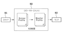
図9は、スキャナとモニタのカラーマネージメントを実現するシステムの構成例を示すブロック図である。 FIG. 9 is a block diagram illustrating a configuration example of a system that realizes color management of a scanner and a monitor.
色変換装置902は、入力デバイスであるスキャナ901から画像データを入力する。次いで、色変換装置902は、入力した画像データを色変換し、出力デバイスであるモニタ903に出力する。色変換装置902は、スキャナのソースプロファイル(Scanner Profile)と、モニタのデスティネーションプロファイル(Monitor Profile)を備える。色変換装置902は、ソースプロファイル(Scanner Profile)を用いて、スキャナの色空間(デバイスRGB)をPCS色空間に変換する。次いで、色変換装置902は、デスティネーションプロファイル(Monitor Profile)を用いて、PCS色空間をモニタの色空間(例えば、sRGBモニタ)に変換する。
The
上記の各プロファイルは、3行3列のマトリックス又は3次元ルックアップテーブル(以下、3D−LUTという。)で表現される。プロファイルを3行3列のマトリックスで表現できない場合は、3D−LUTで表現される。3D−LUTによる色変換処理については、特許文献1及び特許文献2に開示されている。これらの特許文献に開示されている四面体補間においては、4点の格子点データを使用して線形補間演算が行われる。 Each of the above profiles is represented by a matrix of 3 rows and 3 columns or a three-dimensional lookup table (hereinafter referred to as 3D-LUT). If the profile cannot be represented by a 3 × 3 matrix, it is represented by a 3D-LUT. The color conversion processing by 3D-LUT is disclosed in Patent Document 1 and Patent Document 2. In the tetrahedral interpolation disclosed in these patent documents, linear interpolation calculation is performed using four points of grid point data.
ソースプロファイル(Scanner Profile)は、複数の色票チャートに対するデバイスRGBと測色値XYZを例えば式(1)に示すように対応付ける。 The source profile (Scanner Profile) associates device RGB and colorimetric values XYZ with respect to a plurality of color charts as shown in, for example, Expression (1).

線形性の高いデバイスであれば、上記の1次のマトリックスを用いてデバイスRGBと測定値XYZを対応付けできる。しかし、実際には、デバイスRGBのn次項を含めた対応付けを行うことが多い。デバイスRGBの2次項を含める場合は、複数の色票チャートに対するデバイスRGBと測色値XYZを例えば式(2)に示すように対応付ける。 In the case of a device having high linearity, the device RGB and the measurement value XYZ can be associated with each other using the first-order matrix. However, in practice, the association including the n-th term of the device RGB is often performed. When a secondary term of device RGB is included, device RGB and colorimetric values XYZ for a plurality of color charts are associated as shown in, for example, equation (2).
ここで、Mijは2次のマトリックス係数である。また、Cは定数項であり、必要に応じて用いられる。このようにn次のマトリックスでデバイスRGBと測定値XYZとの対応付けをする場合には、プロファイルは、一般的に、3D−LUTで表現される。 Here, M ij is a secondary matrix coefficient. C is a constant term and is used as necessary. As described above, when the device RGB and the measurement value XYZ are associated with each other in an n-order matrix, the profile is generally expressed by a 3D-LUT.
従来技術においては、高次マトリックスで対応付けを行う3D−LUTを用いている。しかし、マトリックスは、全体最適をとるように定義されるために、部分的には必ずしも良好な色変換精度を出せない。そのため、特定の色領域の色変換精度をさらに向上させる技術が提案されている。例えば、特許文献3には、グレー領域の色変換精度を向上させるための技術が開示されている。この技術では、所定の格子間隔で参照値が定義された色変換テーブルAと、この所定の格子間隔よりも小さい格子間隔で参照値が定義されたグレー領域用の色変換テーブルBを備える。そして、入力側の色域に応じて色変換テーブルを切り換えることで、グレー領域の色変換精度を向上させる。 In the prior art, a 3D-LUT that performs association using a higher-order matrix is used. However, since the matrix is defined so as to take overall optimization, it cannot always provide good color conversion accuracy in part. Therefore, a technique for further improving the color conversion accuracy of a specific color region has been proposed. For example, Patent Document 3 discloses a technique for improving the color conversion accuracy of a gray region. This technique includes a color conversion table A in which reference values are defined at a predetermined grid interval, and a color conversion table B for a gray region in which reference values are defined at a grid interval smaller than the predetermined grid interval. The color conversion accuracy in the gray area is improved by switching the color conversion table according to the color gamut on the input side.
特許文献4では、格子点に対応する初期の色変換テーブルをベースにして、格子点近傍の複数のカラーパッチを用いて、色変換テーブルの出力値と測色値、及び格子点までの距離に基づく重み付けによって色変換テーブルを補正する。 In Patent Document 4, based on an initial color conversion table corresponding to a grid point, using a plurality of color patches in the vicinity of the grid point, an output value and a colorimetric value of the color conversion table and a distance to the grid point are set. The color conversion table is corrected by weighting based on it.
特許文献3に開示された方法では、入力デバイスの色域に応じて色変換テーブルを切り換えるため、線形補間の処理が色域に応じて分岐する等、色変換処理が複雑になるという課題がある。また、特許文献4に開示された方法では、色変換精度を部分的に向上させることはできるが、特定の色域での高精度の色変換を実現できない。 In the method disclosed in Patent Document 3, since the color conversion table is switched according to the color gamut of the input device, there is a problem that the color conversion processing becomes complicated, for example, linear interpolation processing branches according to the color gamut. . In addition, the method disclosed in Patent Document 4 can partially improve the color conversion accuracy, but cannot achieve high-accuracy color conversion in a specific color gamut.
そこで、本発明の目的は、特定の色域での高精度な色変換を実現する色変換テーブルを備える色変換装置等を提供することにある。 SUMMARY OF THE INVENTION An object of the present invention is to provide a color conversion device including a color conversion table that realizes highly accurate color conversion in a specific color gamut.
本発明の色処理装置は、第1の色空間を第2の色空間に対応付ける色変換マトリックス又は写像に基づいて得られ、前記第1の色空間の非均等な間隔に位置する少なくとも色票チャートの読み取り値群と前記第2の色空間の色データ群との対応関係を記述した色変換テーブルと、当該非均等な間隔に位置する色票チャートの測色値に基づいて、前記第1の色空間の非均等な間隔に位置する色票チャートの読み取り値に対応する前記第2の色空間の色データを補正することで前記色変換テーブルに記述された対応関係を補正する手段とを備えることを特徴とする。 The color processing apparatus of the present invention is obtained based on a color conversion matrix or mapping that associates the first color space with the second color space, and is at least a color chart that is located at non-uniform intervals in the first color space. Based on the color conversion table describing the correspondence between the read value group and the color data group of the second color space, and the colorimetric values of the color charts located at the non-uniform intervals . Means for correcting the correspondence described in the color conversion table by correcting the color data of the second color space corresponding to the read values of the color chart located at non-uniform intervals in the color space. It is characterized by that.
本発明の色処理方法は、第1の色空間を第2の色空間に対応付ける色変換マトリックス又は写像に基づいて得られ、前記第1の色空間の非均等な間隔に位置する少なくとも色票チャートの読み取り値群と前記第2の色空間の色データ群との対応関係を記述する色変換テーブルを生成するステップと、当該非均等な間隔に位置する色票チャートの測色値に基づいて、前記第1の色空間の非均等な間隔に位置する色票チャートの読み取り値に対応する前記第2の色空間の色データを補正することで前記色変換テーブルに記述された対応関係を補正するステップとを含むことを特徴とする。 The color processing method of the present invention is obtained based on a color conversion matrix or mapping that associates a first color space with a second color space, and is at least a color chart that is located at non-uniform intervals in the first color space. Generating a color conversion table that describes the correspondence between the read value group and the color data group of the second color space, and based on the colorimetric values of the color chart located at the non-uniform intervals , The correspondence described in the color conversion table is corrected by correcting the color data of the second color space corresponding to the read values of the color chart located at non-uniform intervals in the first color space. And a step.
本発明のプログラムは、コンピュータに、第1の色空間を第2の色空間に対応付ける色変換マトリックス又は写像に基づいて得られ、前記第1の色空間の非均等な間隔に位置する少なくとも色票チャートの読み取り値群と前記第2の色空間の色データ群との対応関係を記述する色変換テーブルを生成するステップと、当該非均等な間隔に位置する色票チャートの測色値に基づいて、前記第1の色空間の非均等な間隔に位置する色票チャートの読み取り値に対応する前記第2の色空間の色データを補正することで前記色変換テーブルに記述された対応関係を補正するステップとを実行させることを特徴とする。 The program of the present invention is obtained on the basis of a color conversion matrix or mapping that associates a first color space with a second color space, and at least a color chart located at non-uniform intervals in the first color space. Based on the step of generating a color conversion table that describes the correspondence between the read value group of the chart and the color data group of the second color space, and the colorimetric values of the color chart located at the non-uniform intervals The correspondence relationship described in the color conversion table is corrected by correcting the color data of the second color space corresponding to the read values of the color chart located at non-uniform intervals in the first color space. The step of performing is performed.
本発明においては、第1の色空間を第2の色空間に変換する色変換テーブルを生成するにあたり、色票チャートの実際の測色値に基づき色変換テーブルを補正するため、色再現にとって重要な色域における色変換精度を向上させることができる。 In the present invention, in generating a color conversion table for converting the first color space to the second color space, the color conversion table is corrected based on the actual colorimetric values of the color chart, which is important for color reproduction. Color conversion accuracy in a wide color gamut can be improved.
以下、図面を参照しながら本発明の実施形態を詳細に説明する。 Hereinafter, embodiments of the present invention will be described in detail with reference to the drawings.
(実施形態1)
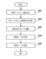
図1は、スキャナのソースプロファイル(Scanner Profile)を生成する処理の流れを示すフローチャートである。
(Embodiment 1)
FIG. 1 is a flowchart showing a flow of processing for generating a scanner source profile.
S101において、測色器は、あらかじめ用意した複数の色票チャートを測色する。この測色値は、色変換装置に出力される。 In S101, the colorimeter measures a plurality of color charts prepared in advance. This colorimetric value is output to the color conversion device.
S102において、スキャナは、それぞれの色票チャートを読み込み、デバイスRGB値を求め、色変換装置に出力する。尚、色変換装置は、パーソナルコンピュータにプロファイル作成アプリケーションとして図1、2の処理を実施可能なプログラムをインストールすることで実現される。 In S102, the scanner reads each color chart, obtains device RGB values, and outputs them to the color conversion device. The color conversion apparatus is realized by installing a program capable of performing the processing of FIGS. 1 and 2 as a profile creation application in a personal computer.
S103において、色変換装置は、S102で求められたデバイスRGB値と、S1012で求められた測色値に基づいて、全体的なエネルギーを最小(例えば、色差最小)にする高次の最適な色変換マトリックスを生成する。 In step S103, the color conversion apparatus determines a high-order optimum color that minimizes the overall energy (for example, minimum color difference) based on the device RGB value obtained in step S102 and the colorimetric value obtained in step S1012. Generate a transformation matrix.
S104において、色変換装置は、スキャナの色空間を所定の数の格子点(例えば、スキャナの色域全体に分散する17格子点)で分割し、S103で生成した色変換マトリックスを用いて、各格子点のデバイスRGBに対する出力値XYZを計算する。次いで、色変換装置は、デバイスRGBと、出力値XYZの対応関係が記述された色変換テーブルを生成する。すなわち、この色変換テーブルは、第1の色空間(例えば、デバイスRGB)の第1の色データと第2の色空間(CIEXYZ)の第2の色データとの対応関係を記述するテーブルである。色変換マトリックスの生成方法の一例として、特開2005−110089号公報に開示された方法がある。この方法は、擬似逆行列を利用したものである。色変換マトリックスを生成するにあたっては、その他の種々の公知の方法も利用可能である。さらに、色変換装置は、色変換マトリクスではなく、写像を利用してもよい。そこで、本実施形態では、式(3)に示すように、デバイスRGBと、デバイスRGBに対する出力値XYZを写像Fで対応付ける。
(X,Y,Z)=F(R,G,B) (3)
In S104, the color conversion apparatus divides the scanner color space by a predetermined number of grid points (for example, 17 grid points distributed over the entire color gamut of the scanner), and uses the color conversion matrix generated in S103 to The output value XYZ for the grid point device RGB is calculated. Next, the color conversion apparatus generates a color conversion table in which a correspondence relationship between the device RGB and the output value XYZ is described. That is, this color conversion table is a table that describes the correspondence between the first color data in the first color space (for example, device RGB) and the second color data in the second color space (CIEXYZ). . As an example of a method for generating a color conversion matrix, there is a method disclosed in Japanese Patent Laid-Open No. 2005-110089. This method uses a pseudo inverse matrix. Various other known methods can be used to generate the color conversion matrix. Further, the color conversion device may use a mapping instead of a color conversion matrix. Therefore, in this embodiment, as shown in Expression (3), the device RGB and the output value XYZ for the device RGB are associated with the mapping F.
(X, Y, Z) = F (R, G, B) (3)
なお、上記の式では、ソースプロファイルの出力値としてCIEXYZを利用しているが、CIELabを利用してもよい。ここで、CIEXYZとは、CIEによって定義された三原色XYZによる色の記述方法のことである。CIELabとは、CIEXYZを知覚的に理解しやすく考案された色空間のことである。 In the above formula, CIEXYZ is used as the output value of the source profile, but CIELab may be used. Here, CIEXYZ is a color description method using the three primary colors XYZ defined by CIE. CIELab is a color space devised so that CIEXYZ can be perceptually understood.
図2は、本実施形態における、特定格子点の再現性を向上した色変換テーブルの生成処理の流れを示すフローチャートである。 FIG. 2 is a flowchart showing the flow of a color conversion table generation process with improved reproducibility of specific grid points in the present embodiment.
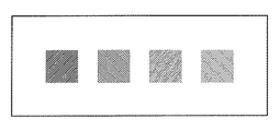
図3は、高精度なマッチング実現するため色票チャートを示す図である。 FIG. 3 is a diagram showing a color chart for realizing highly accurate matching.
説明を簡略化するために、本実施形態で用いる色票チャートは、異なる濃度のグレー色票チャート(色票チャート1〜4)とする。尚、色票チャートは、特定の記憶色(肌色、緑、青)を表すものであってもよい。 In order to simplify the description, the color chart used in the present embodiment is a gray color chart with different densities (color charts 1 to 4). Note that the color chart may represent a specific memory color (skin color, green, blue).
S201において、測色器は、異なる濃度のグレー色票チャートを読み込み、測色値を得る。 In S201, the colorimeter reads a gray color chart with different densities and obtains a colorimetric value.
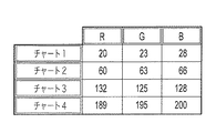
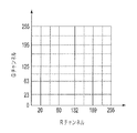
図4は、グレー色票チャートをスキャナで読み込んだ結果得られる色票チャート毎のデバイスRGB値を示す図である。 FIG. 4 is a diagram showing device RGB values for each color chart obtained as a result of reading a gray color chart by a scanner.
図4に示される数値は、各々が8ビットで表現されるデバイスRGB値のRチャネル、Gチャネル、Bチャネルを10進数に変換した値である。図4によると、Rチャネル、Gチャネル、Bチャネルは0〜255の値となる。例えば、色票チャート1のデバイスRGB値は、(20、23、28)である。図4からわかるように、色票チャートがニュートラルグレーであったとしても、必ずしも、デバイスRGB値がグレーになるとは限らない。 The numerical values shown in FIG. 4 are values obtained by converting the R channel, the G channel, and the B channel of device RGB values each represented by 8 bits into decimal numbers. According to FIG. 4, the R channel, the G channel, and the B channel have values from 0 to 255. For example, the device RGB value of the color chart 1 is (20, 23, 28). As can be seen from FIG. 4, even if the color chart is neutral gray, the device RGB values are not necessarily gray.
3D−LUTの形式で記述されるソースプロファイルには、デバイスRGBのすべての色域を特定の格子点数で均等分割することにより得られる格子点データと、当該格子点データに対する出力値の対応関係が記述される。これに対して、本実施形態においては、図4に示されたデバイスRGB値を特定格子点データとして利用し、特定格子点データと、特定格子点データに対する出力値の対応関係を色変換テーブルに記述する。 The source profile described in the 3D-LUT format has a correspondence relationship between grid point data obtained by equally dividing all the color gamuts of the device RGB by a specific number of grid points and output values for the grid point data. Described. In contrast, in the present embodiment, the device RGB values shown in FIG. 4 are used as specific grid point data, and the correspondence between the specific grid point data and the output value for the specific grid point data is stored in the color conversion table. Describe.
S202において、色変換装置は、図4に示されたデバイスRGB値に基づきチャネル毎に特定格子点データを設定する。 In S202, the color conversion apparatus sets specific grid point data for each channel based on the device RGB values shown in FIG.
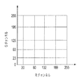
図5は、GチャネルとRチャネルの特定格子点データを示す図である。 FIG. 5 is a diagram illustrating specific grid point data of the G channel and the R channel.
図5においては、RチャンネルおよびGチャンネルの特定格子点データからなる平面体が示されているが、実際には、Rチャンネル、Gチャンネル、Bチャンネルの特定格子点データ(デバイスRGB値)からなる立方体となる。 In FIG. 5, a plane body composed of specific grid point data of the R channel and G channel is shown, but actually, it consists of specific grid point data (device RGB values) of the R channel, G channel, and B channel. It becomes a cube.
N個の色票チャートを与えた場合には、デバイスRGB値が重複しない限り、N個の格子点データが生成される。また、最小値0と最大値255は格子点データとして必要となる。
When N color charts are given, N grid point data are generated as long as device RGB values do not overlap. Further, the
S203において、色変換装置は、色変換テーブルを生成するのに必要な格子点データを設定する。色変換テーブルを生成するのに必要な格子点データの数をM個とすれば、必要となる格子点データを追加する。例えば、4種類の色票チャートを与えた場合には6つの格子点データが生成されるが、色変換テーブルを生成するのに9つの格子点データが必要な場合には、3つの格子点データを追加する必要がある。 In S203, the color conversion apparatus sets lattice point data necessary for generating a color conversion table. If the number of grid point data required to generate the color conversion table is M, the required grid point data is added. For example, when four types of color charts are given, six grid point data are generated, but when nine grid point data are required to generate a color conversion table, three grid point data are generated. Need to be added.
図6は、追加された格子点データを含めた最終的な格子点データを平面体で表した図である。図6に示す破線の位置に格子点データを追加することにより、最終的な格子点データを9つにする。各チャンネルで3つの格子点データを追加する必要があるため、広い格子点間隔を有する位置に任意に格子点データを設定する。例えば、追加する格子点データの設定位置は、単純に元の格子点データ間の中心位置であってもよいし、元の格子点データをシュプライン曲線で近似して、それに基づき格子点データを設定してもよい。 FIG. 6 is a diagram showing the final lattice point data including the added lattice point data in a plane. By adding lattice point data to the position of the broken line shown in FIG. 6, the final lattice point data is reduced to nine. Since it is necessary to add three grid point data for each channel, grid point data is arbitrarily set at a position having a wide grid point interval. For example, the setting position of the grid point data to be added may be simply the center position between the original grid point data, or the original grid point data is approximated by a Spline curve, and the grid point data is converted based thereon. It may be set.
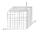
図7は、追加された格子点データを含めた最終的な格子点データを立方体で表した図である。 FIG. 7 is a diagram showing the final lattice point data including the added lattice point data in a cube.
デバイス色空間に対して、各ラインで構成される面の交点が格子点データとなる。一般的に、線形補間処理においては処理速度の側面から格子点データの間隔が均等であるのが望ましいが、例えば、特開2000−22973号公報が開示する方法を利用すれば、格子点の間隔が非均等な任意の格子点データに対しても高速な補間処理が実現できる。このように各チャンネルで異なる格子点データを設定しても、3D−LUTの線形補間処理は実現可能である。 With respect to the device color space, the intersections of the surfaces formed by the respective lines become grid point data. In general, in linear interpolation processing, it is desirable that the interval between grid point data is uniform from the viewpoint of processing speed. For example, if a method disclosed in Japanese Patent Laid-Open No. 2000-22773 is used, the interval between grid points is High-speed interpolation processing can be realized even for arbitrary grid point data with non-uniformity. In this way, even when different grid point data is set for each channel, 3D-LUT linear interpolation processing can be realized.
S204において、各格子点のデバイスRGB値と上述した写像F(式3)を用いて出力値XYZを取得して、デバイスRGB値と出力値XYZの対応関係が記述された色変換テーブルを生成する。 In S204, the output value XYZ is acquired using the device RGB value of each lattice point and the above-described mapping F (Equation 3), and a color conversion table describing the correspondence between the device RGB value and the output value XYZ is generated. .
S205において、S204で生成した色変換テーブルに記述された対応関係の一部を補正する。すなわち、S205において、全ての格子点データのうちの、特定の色票チャートから得られた特定格子点データに対応する出力値XYZを、色票チャートの実際の測色値に基づいて補正する。その理由は、写像Fは、スキャナの色域全体をみて最適化されているため部分的には色票チャートの実際の測色値を反映しないからである。 In S205, a part of the correspondence described in the color conversion table generated in S204 is corrected. That is, in S205, the output value XYZ corresponding to the specific grid point data obtained from the specific color chart among all the grid point data is corrected based on the actual colorimetric values of the color chart. This is because the mapping F is optimized by looking at the entire color gamut of the scanner, and thus does not partially reflect the actual colorimetric values of the color chart.
本実施形態では、高精度なマッチングを実現したい色の色票チャートから得られる特定格子点データに対応する出力値XYZを、色票チャートの実際の測色値に基づいて補正する。さらに、これらの特定格子点データに対応する出力値XYZの補正量が大きい場合には、その大きさに応じて、周りの格子点データに対応する出力値XYZを補正してもよい。 In the present embodiment, the output value XYZ corresponding to the specific grid point data obtained from the color chart of the color for which high-precision matching is desired is corrected based on the actual colorimetric value of the color chart. Furthermore, when the correction amount of the output value XYZ corresponding to these specific grid point data is large, the output value XYZ corresponding to the surrounding grid point data may be corrected according to the amount.
本実施形態では、任意の格子点データとそれに対応する出力値XYZの対応関係が記述された色変換テーブルを生成後、その色変換テーブルに対して、色票チャートの実際の測色値に基づいて特定格子点データに対応する出力値XYZの補正を行う。これにより、色再現にとって重要な色域での高精度なマッピングを実現する色変換テーブルを提供することができる。 In this embodiment, after generating a color conversion table in which the correspondence between arbitrary grid point data and the corresponding output value XYZ is generated, the color conversion table is based on the actual colorimetric values of the color chart. Thus, the output value XYZ corresponding to the specific grid point data is corrected. Thereby, it is possible to provide a color conversion table that realizes highly accurate mapping in a color gamut important for color reproduction.
(実施形態2)
実施形態1では、ソースプロファイルの作成を例にして詳細を説明したが、色変換テーブルにおいて出力色空間がPCS色空間である必要はない。例えば、スキャナ以外の入力デバイスRGBを標準的なxRGB色空間(例えばsRGB)へマッピングすることもできる。この場合、上述した写像Fの変わりに、写像Gを用いて色変換テーブルを生成する。
(R,G,B)standard=G(R,G,B)device (4)
(Embodiment 2)
In the first embodiment, the details have been described using the creation of the source profile as an example, but the output color space does not have to be the PCS color space in the color conversion table. For example, input devices RGB other than the scanner can be mapped to a standard xRGB color space (for example, sRGB). In this case, a color conversion table is generated using the map G instead of the map F described above.
(R, G, B) standard = G (R, G, B) device (4)
実施形態2は、実施形態1と同様に、高精度なマッピング精度を実現する色票チャートから、格子点データを生成し、最終的に必要とする格子点データの数にする。これらの格子点データと、それに対応する出力値を用いて色変換テーブルを生成した後、特定格子点データに対応する出力値を、実際の測色値(xRGB値)で補正すればよい。 In the second embodiment, as in the first embodiment, grid point data is generated from a color chart that realizes high-precision mapping accuracy, and is finally set to the number of required grid point data. After generating a color conversion table using these grid point data and corresponding output values, the output values corresponding to the specific grid point data may be corrected with actual colorimetric values (xRGB values).
このように、本発明においては、第1の色空間はデバイスに依存するが、第2の色空間はデバイスに依存しない。 Thus, in the present invention, the first color space depends on the device, but the second color space does not depend on the device.
(他の実施形態)
前述した実施形態の機能を実現するように前述した実施形態の構成を動作させるプログラムを記録媒体に記憶させ、該記録媒体に記憶されたプログラムをコードとして読み出し、コンピュータにおいて実行する処理方法も上述の実施形態の範疇に含まれる。該記録媒体は、コンピュータ読み取り可能な記録媒体である。また、前述のプログラムが記憶された記録媒体はもちろんそのプログラム自体も上述の実施形態に含まれる。かかる記録媒体としてはたとえばフロッピー(登録商標)ディスク、ハードディスク、光ディスク、光磁気ディスク、CD―ROM、磁気テープ、不揮発性メモリカード、ROMを用いることができる。また前述の記録媒体に記憶されたプログラム単体で処理を実行しているものに限らず、他のソフトウエア、拡張ボードの機能と共同して、OS上で動作し前述の実施形態の動作を実行するものも前述した実施形態の範疇に含まれる。
(Other embodiments)
The processing method for storing the program for operating the configuration of the above-described embodiment so as to realize the function of the above-described embodiment on a recording medium, reading the program stored on the recording medium as a code, and executing the program on the computer is also described above. It is included in the category of the embodiment. The recording medium is a computer-readable recording medium. In addition to the recording medium storing the above-described program, the program itself is included in the above-described embodiment. As such a recording medium, for example, a floppy (registered trademark) disk, a hard disk, an optical disk, a magneto-optical disk, a CD-ROM, a magnetic tape, a nonvolatile memory card, and a ROM can be used. In addition, the processing is not limited to the single program stored in the recording medium described above, but operates on the OS in cooperation with other software and the function of the expansion board to execute the operation of the above-described embodiment. This is also included in the category of the embodiment described above.
801 スキャナ
802 色変換装置
803 プリンタ
901 スキャナ
902 色変換装置
903 モニタ
801
Claims (9)
当該非均等な間隔に位置する色票チャートの測色値に基づいて、前記第1の色空間の非均等な間隔に位置する色票チャートの読み取り値に対応する前記第2の色空間の色データを補正することで前記色変換テーブルに記述された対応関係を補正する手段と
を備えることを特徴とする色処理装置。 At least a color chart chart reading value group obtained on the basis of a color conversion matrix or mapping that maps the first color space to the second color space and located at non-uniform intervals in the first color space, and the second color space. A color conversion table that describes the correspondence with the color data group in the color space of
Based on the colorimetric value of the color chart chart positioned on the non-uniform spacing, color of the second color space corresponding to the reading of the color chart chart located in the non-uniform spacing of the first color space color processing apparatus characterized by comprising a means for correcting the described relationship to the color conversion table by correcting the data.
当該非均等な間隔に位置する色票チャートの測色値に基づいて、前記第1の色空間の非均等な間隔に位置する色票チャートの読み取り値に対応する前記第2の色空間の色データを補正することで前記色変換テーブルに記述された対応関係を補正するステップと
を含むことを特徴とする色処理方法。 At least a color chart chart reading value group obtained on the basis of a color conversion matrix or mapping that maps the first color space to the second color space and located at non-uniform intervals in the first color space, and the second color space. Generating a color conversion table that describes a correspondence relationship with the color data group in the color space;
Based on the colorimetric value of the color chart chart positioned on the non-uniform spacing, color of the second color space corresponding to the reading of the color chart chart located in the non-uniform spacing of the first color space And correcting the correspondence described in the color conversion table by correcting the data .
第1の色空間を第2の色空間に対応付ける色変換マトリックス又は写像に基づいて得られ、前記第1の色空間の非均等な間隔に位置する少なくとも色票チャートの読み取り値群と前記第2の色空間の色データ群との対応関係を記述する色変換テーブルを生成するステップと、
当該非均等な間隔に位置する色票チャートの測色値に基づいて、前記第1の色空間の非均等な間隔に位置する色票チャートの読み取り値に対応する前記第2の色空間の色データを補正することで前記色変換テーブルに記述された対応関係を補正するステップと
を実行させるためのプログラム。 On the computer,
At least a color chart chart reading value group obtained on the basis of a color conversion matrix or mapping that maps the first color space to the second color space and located at non-uniform intervals in the first color space, and the second color space. Generating a color conversion table that describes a correspondence relationship with the color data group in the color space;
Based on the colorimetric value of the color chart chart positioned on the non-uniform spacing, color of the second color space corresponding to the reading of the color chart chart located in the non-uniform spacing of the first color space And correcting the correspondence described in the color conversion table by correcting the data .
Priority Applications (2)
| Application Number | Priority Date | Filing Date | Title |
|---|---|---|---|
| JP2007162722A JP5354875B2 (en) | 2007-06-20 | 2007-06-20 | Color processing apparatus and color processing method |
| US12/141,226 US8184349B2 (en) | 2007-06-20 | 2008-06-18 | Color management system |
Applications Claiming Priority (1)
| Application Number | Priority Date | Filing Date | Title |
|---|---|---|---|
| JP2007162722A JP5354875B2 (en) | 2007-06-20 | 2007-06-20 | Color processing apparatus and color processing method |
Publications (3)
| Publication Number | Publication Date |
|---|---|
| JP2009004991A JP2009004991A (en) | 2009-01-08 |
| JP2009004991A5 JP2009004991A5 (en) | 2010-08-05 |
| JP5354875B2 true JP5354875B2 (en) | 2013-11-27 |
Family
ID=40136144
Family Applications (1)
| Application Number | Title | Priority Date | Filing Date |
|---|---|---|---|
| JP2007162722A Active JP5354875B2 (en) | 2007-06-20 | 2007-06-20 | Color processing apparatus and color processing method |
Country Status (2)
| Country | Link |
|---|---|
| US (1) | US8184349B2 (en) |
| JP (1) | JP5354875B2 (en) |
Families Citing this family (11)
| Publication number | Priority date | Publication date | Assignee | Title |
|---|---|---|---|---|
| KR101925370B1 (en) * | 2012-01-31 | 2018-12-05 | 한국전자통신연구원 | Apparatus and method of correcting color for image projection device |
| WO2013119852A1 (en) * | 2012-02-07 | 2013-08-15 | Zencolor Corporation | Mobile shopping tools utilizing color-based identification, searching and matching enhancement of supply chain and inventory management systems |
| US9607404B2 (en) | 2012-02-07 | 2017-03-28 | Zencolor Corporation | System for normalizing, codifying and categorizing color-based product and data based on a universal digital color system |
| US9047633B2 (en) | 2012-02-07 | 2015-06-02 | Zencolor Corporation | System and method for identifying, searching and matching products based on color |
| US8600153B2 (en) | 2012-02-07 | 2013-12-03 | Zencolor Corporation | System and method for normalization and codification of colors for dynamic analysis |
| US9436704B2 (en) | 2012-02-07 | 2016-09-06 | Zencolor Corporation | System for normalizing, codifying and categorizing color-based product and data based on a universal digital color language |
| US10460475B2 (en) | 2012-02-07 | 2019-10-29 | Zencolor Global, Llc | Normalization of color from a captured image into a universal digital color system for specification and matching |
| JP5981768B2 (en) * | 2012-05-15 | 2016-08-31 | キヤノン株式会社 | Color processing apparatus and method |
| US9087357B2 (en) | 2013-10-16 | 2015-07-21 | Zencolor Corporation | System for normalizing, codifying and categorizing color-based product and data based on a universal digital color language |
| CN105706434B (en) * | 2013-11-15 | 2019-01-08 | 富士胶片株式会社 | Color-conversion table producing device and method |
| JP6821418B2 (en) | 2016-12-16 | 2021-01-27 | キヤノン株式会社 | Image processing equipment, image processing methods, and programs |
Family Cites Families (18)
| Publication number | Priority date | Publication date | Assignee | Title |
|---|---|---|---|---|
| JPS5816180B2 (en) | 1977-04-01 | 1983-03-30 | 大日本スクリ−ン製造株式会社 | Signal interpolation method in memory device |
| JPH11220630A (en) * | 1998-02-03 | 1999-08-10 | Fuji Photo Film Co Ltd | Method for generating three-dimensional look up table, image processor executing the same and digital color printer provided with the same |
| JP3912903B2 (en) | 1998-07-02 | 2007-05-09 | キヤノン株式会社 | Data conversion method and apparatus |
| JP2000253270A (en) | 1999-03-04 | 2000-09-14 | Dainippon Printing Co Ltd | Color conversion table generator, generating method, storage medium recording color conversion table generating program and color converter |
| US6980326B2 (en) | 1999-12-15 | 2005-12-27 | Canon Kabushiki Kaisha | Image processing method and apparatus for color correction of an image |
| JP2001186365A (en) | 1999-12-27 | 2001-07-06 | Canon Inc | Picture processing method, picture processor and recording medium |
| JP2001320594A (en) | 2000-05-10 | 2001-11-16 | Shinko Electric Co Ltd | Image display device and gray balance adjustment method |
| JP4217398B2 (en) | 2001-09-12 | 2009-01-28 | キヤノン株式会社 | Image data processing method, image data processing apparatus, storage medium, and program |
| JP4065482B2 (en) | 2001-09-18 | 2008-03-26 | キヤノン株式会社 | Image data processing method, apparatus, storage medium, and program |
| JP4227322B2 (en) | 2001-10-01 | 2009-02-18 | キヤノン株式会社 | Image processing method, image processing apparatus, storage medium, and program |
| JP3943973B2 (en) | 2002-03-20 | 2007-07-11 | キヤノン株式会社 | Image processing apparatus and method |
| JP4272880B2 (en) | 2002-12-18 | 2009-06-03 | キヤノン株式会社 | Color correction method, image processing apparatus, and lookup table |
| JP2004236200A (en) * | 2003-01-31 | 2004-08-19 | Canon Inc | Method and device for editing color processing parameter |
| JP2004276266A (en) * | 2003-03-12 | 2004-10-07 | Seiko Epson Corp | Device, method and program for correcting color space correspondence relation |
| JP4236255B2 (en) * | 2003-07-16 | 2009-03-11 | キヤノン株式会社 | Color image forming apparatus and color control method |
| JP4250493B2 (en) | 2003-10-01 | 2009-04-08 | キヤノン株式会社 | Color conversion matrix generation method, color conversion table creation method and program |
| JP4632438B2 (en) | 2005-08-02 | 2011-02-16 | キヤノン株式会社 | Color processing method, and color processing apparatus and method for creating a lookup table |
| US7495802B2 (en) * | 2006-06-16 | 2009-02-24 | Kabushiki Kaisha Toshiba | Image processing apparatus, image processing method and image processing program |
-
2007
- 2007-06-20 JP JP2007162722A patent/JP5354875B2/en active Active
-
2008
- 2008-06-18 US US12/141,226 patent/US8184349B2/en active Active
Also Published As
| Publication number | Publication date |
|---|---|
| US8184349B2 (en) | 2012-05-22 |
| US20080316513A1 (en) | 2008-12-25 |
| JP2009004991A (en) | 2009-01-08 |
Similar Documents
| Publication | Publication Date | Title |
|---|---|---|
| JP5354875B2 (en) | Color processing apparatus and color processing method | |
| JP5269042B2 (en) | Image processing apparatus, image processing method, and lookup table generation method | |
| JP5043513B2 (en) | Color processing apparatus and method | |
| US8045222B2 (en) | Image processing method, image processing apparatus, computer program product, and recording medium for image processing | |
| JP4263131B2 (en) | Color conversion method and image processing apparatus | |
| JP4238992B2 (en) | Color image processing method, color image processing apparatus, color image processing program, and storage medium | |
| JP5854034B2 (en) | Color processing apparatus, image forming apparatus, and program | |
| US20050195415A1 (en) | System and method for gamut mapping control | |
| US8111423B2 (en) | Image processing device and image processing method | |
| JP4250493B2 (en) | Color conversion matrix generation method, color conversion table creation method and program | |
| JP5882763B2 (en) | Image processing apparatus and profile creation method | |
| JP5854066B2 (en) | Color processing apparatus, image forming apparatus, and program | |
| US7880942B1 (en) | Method and apparatus for converting color coefficients between color spaces | |
| JP2010074317A (en) | Image processor, image processing program, and image processing method | |
| JP2000253270A (en) | Color conversion table generator, generating method, storage medium recording color conversion table generating program and color converter | |
| JP5159565B2 (en) | Color processing apparatus and method | |
| JP2006197395A (en) | Image processing method and apparatus thereof | |
| JP4228207B2 (en) | Color image processing method, color image processing apparatus, color image processing program, and storage medium | |
| JP2011019030A (en) | Conversion profile generation method and printer | |
| JP4228208B2 (en) | Color image processing method, color image processing apparatus, color image processing program, and storage medium | |
| JP2008072550A (en) | Color processing method, color processing apparatus, image forming apparatus, program and recording medium | |
| JP2011151491A (en) | Device and program for color conversion | |
| US8570591B2 (en) | Color conversion device, color conversion method and computer readable medium calculate a minimum required black amount in regard to colors that are reproduced by an output device that actually outputs | |
| Zeng | Color accuracy in ICC color management system | |
| JP5962551B2 (en) | Color processing apparatus, image forming apparatus, and program |
Legal Events
| Date | Code | Title | Description |
|---|---|---|---|
| A521 | Written amendment |
Free format text: JAPANESE INTERMEDIATE CODE: A523 Effective date: 20100621 |
|
| A621 | Written request for application examination |
Free format text: JAPANESE INTERMEDIATE CODE: A621 Effective date: 20100621 |
|
| RD02 | Notification of acceptance of power of attorney |
Free format text: JAPANESE INTERMEDIATE CODE: A7422 Effective date: 20101106 |
|
| A977 | Report on retrieval |
Free format text: JAPANESE INTERMEDIATE CODE: A971007 Effective date: 20111122 |
|
| A131 | Notification of reasons for refusal |
Free format text: JAPANESE INTERMEDIATE CODE: A131 Effective date: 20111125 |
|
| A521 | Written amendment |
Free format text: JAPANESE INTERMEDIATE CODE: A523 Effective date: 20120124 |
|
| A02 | Decision of refusal |
Free format text: JAPANESE INTERMEDIATE CODE: A02 Effective date: 20120522 |
|
| A521 | Written amendment |
Free format text: JAPANESE INTERMEDIATE CODE: A523 Effective date: 20120822 |
|
| RD13 | Notification of appointment of power of sub attorney |
Free format text: JAPANESE INTERMEDIATE CODE: A7433 Effective date: 20120824 |
|
| A521 | Written amendment |
Free format text: JAPANESE INTERMEDIATE CODE: A821 Effective date: 20120824 |
|
| A911 | Transfer to examiner for re-examination before appeal (zenchi) |
Free format text: JAPANESE INTERMEDIATE CODE: A911 Effective date: 20120913 |
|
| A912 | Re-examination (zenchi) completed and case transferred to appeal board |
Free format text: JAPANESE INTERMEDIATE CODE: A912 Effective date: 20121116 |
|
| A61 | First payment of annual fees (during grant procedure) |
Free format text: JAPANESE INTERMEDIATE CODE: A61 Effective date: 20130827 |
|
| R151 | Written notification of patent or utility model registration |
Ref document number: 5354875 Country of ref document: JP Free format text: JAPANESE INTERMEDIATE CODE: R151 |